WG security WGPPTR58 EAS System User Manual Manual Premier Guard 011306A
WG Security Products, Inc EAS System Manual Premier Guard 011306A
Contents
- 1. Manual for Premier Guard
- 2. User Manual for Premier Pro
Manual for Premier Guard

58Khz
Premier GuardTM
Installation Manual
Version: Jan 2006
Manual Part Number: WG-PGTR58-IM
(011306A)
WG SECURITY PRODUCTS INC.
3031 Tisch Way, Suite 602, San Jose, CA 95128 (USA)
http://www.wgspi.com

Technical Support Contact Information
North America
South America
Tel: 818-763-9186
Fax: 818-255-0514
Email: svc@sensorsense.com
Rest of World
Tel: 408-241-8000
Fax: 408-241-8082
Email: support@wgspi.com
WARRANTY DISCLAIMER
WG Security Products Inc. makes no representation o
r
warranty with respect to the contents hereof and
specifically disclaims any implied warranties o
f
merchantability or fitness for any particular purpose.
Further, WG Security Products Inc. reserves the right
to revise this publication and make changes from time
to time in the content hereof without obligation of WG
Security Products Inc. to notify any person of such
revision or changes.
CRITICAL NOTE
As specified by FCC Regulations 15.21, any
changes or modifications not expressly approved
by the party responsible for compliance of this
equipment, will void the user’s permission and
authority to operate this equipment.
FCC ID: P9I-WGPPTR58
“This device complies with Part 15 of the FCC Rules. Operation is
subject to the following two conditions: (1) This device may not cause
harmful interference, and (2) This device must accept any interference
received, including interference that may cause undesired operation.”
TABLE OF CONTENTS
OVERVIEW .............................................................................................................................1
SYSTEM OVERVIEW................................................................................................................1
SYSTEM CONFIGURATION .......................................................................................................2
PREMIER GUARD FEATURES & BENEFITS.................................................................................2
SPECIFICATIONS ....................................................................................................................3
PRE-INSTALLATION INFORMATION ....................................................................................4
PREMIER LINE CONTROL UNIT (PLCU) DIMENSIONS ................................................................4
PREMIER GUARD PEDESTAL DIMENSIONS ................................................................................5
PREMIER GUARD BASE FOOTPRINT DIMENSIONS......................................................................6
CONNECTION DIAGRAM ..........................................................................................................7
INSTALLATION.......................................................................................................................8
INSTALLATION SITE POWER SUPPLY VERIFICATION ...................................................................8
PARTS LIST –PREMIER GUARD SYSTEM...................................................................................8
QUICK START FOR SYSTEM CONNECTIONS ..............................................................................9
Transformer Box............................................................................................................10
Installing the PLCU........................................................................................................11
Connecting the Pedestal ...............................................................................................12
CABLE AND CONNECTOR CONNECTIONS ................................................................................14
POWER CORD NOTICES........................................................................................................18
North American Power Supply Cords ............................................................................18
International Power Supply Cord ...................................................................................18
EXTERNAL RELAY INTERFACE ...............................................................................................19
FUSE REPLACEMENT INFORMATION .......................................................................................20
IR REMOTE CONTROL KEYPAD DESCRIPTION ...............................................................23
TUNING PROCEDURES & TIPS...........................................................................................24
REMOTE CONTROL PROGRAMMING ................................................................................25
ADDENDUM 1 .......................................................................................................................33
PEDESTAL SENSITIVITY ADJUSTMENT GUIDE ..........................................................................33

Premier Guard Installation Manual
1
OVERVIEW
System Overview
Premier Guard systems consist of one a transceiver pedestal, a 58Khz Premier Line Control
Unit (WGPLCU58), and a stepdown power transformer box. The PLCU provides all the
control functions for the transceiver, including tag detection and alarm notification.
Detection Range (either side of pedestal)
Europe USA
Micro Pencil Tag 0.9 m 3 ft
Premier Line Control Unit
WGPLCU58
24vac Stepdown Transformer
WGPS2490-1
Transceiver Antenna
(Pedestal)
Premier Guard Installation Manual
2
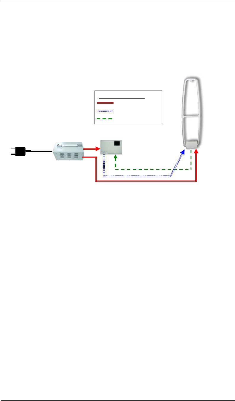
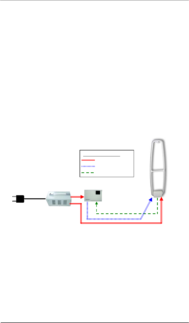
System Configuration
The PLCU controls the transceiver through the TX control cable. All detection information is
received through the RX cable. The Transformer power box powers the PLCU and
transceiver through two separate cables. The following diagram illustrates the connections.
Premier Guard Features & Benefits
• Digital Signal Processing
The Premier Guard applies the latest and most advanced DSP technology for anti-
theft solutions, virtually eliminating false alarms while maintaining considerable
detection range.
• Self Tuning Electronics
Benefiting from its fully digital electronics, the Premier Guard constantly evaluates the
environment, automatically adapting to changes in the environment to enhance its
performance.
• Integrated Audible and Visual Notification
Alarm notification is built into the Premier Guard on both the pedestal and controller.
Connections Legend
Power Bus
TX Control Signal
RX Signal
Premier Guard
Transceiver Antenna
24vac
24vac
Transforme
r
PLCU
110/220vac
24vac

Premier Guard Installation Manual
3
Specifications
Electrical
Primary Input
(Stepdown Transformer)
230/115 ±10% @50/60Hz (Input)
24vac @ 4A (Output)
Pedestal Input 24vac @50/60Hz
PLCU Input 24vac @50/60Hz
Primary Rated Current 0.55Amax@220vac 1.1A max@110vac
Pedestal Rated Current 1.8A @ 24vac
PLCU Rated Current 0.5A @ 24vac
Transmitter Output 1.6ms Burst
Operating Frequency 58Khz
Mechanical
Premier Guard Pedestal Transceiver
Height 1523.6mm (60”)
Width 374.5mm (14.8”)
Thickness 24mm (1.0”)
Weight 17Kg (37.5 lbs)
WGPLCU58 Control Unit
Length 314mm (11.6”) (Including Mounting Bar)
Width 193mm (7.5”)
Depth 82mm (3.2”) (Including Mounting Bar)
Weight 3.5Kg (7.7 lbs)
WGPS2490-1 Stepdown Transformer
Length 225mm (8.9”)
Width 143mm (5.6”)
Depth 103mm (4.1”)
Weight 3Kg (6.6 lbs)
Environmental
Operating Temperature
0 to 49°C (32° to 120°F)
Relative Humidity 0 to 85% non-condensing
Operating Altitude 2,000m (6,500 ft)
Premier Guard Installation Manual
4
PRE-INSTALLATION INFORMATION
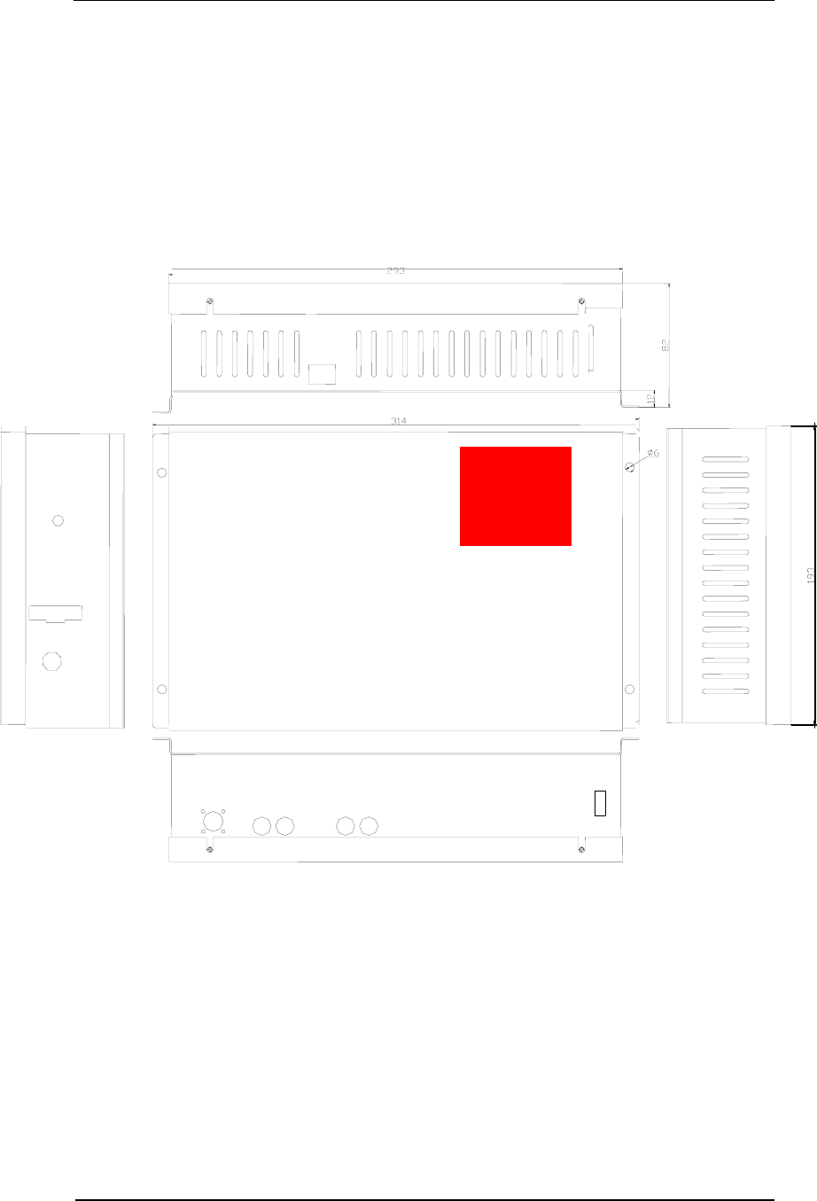
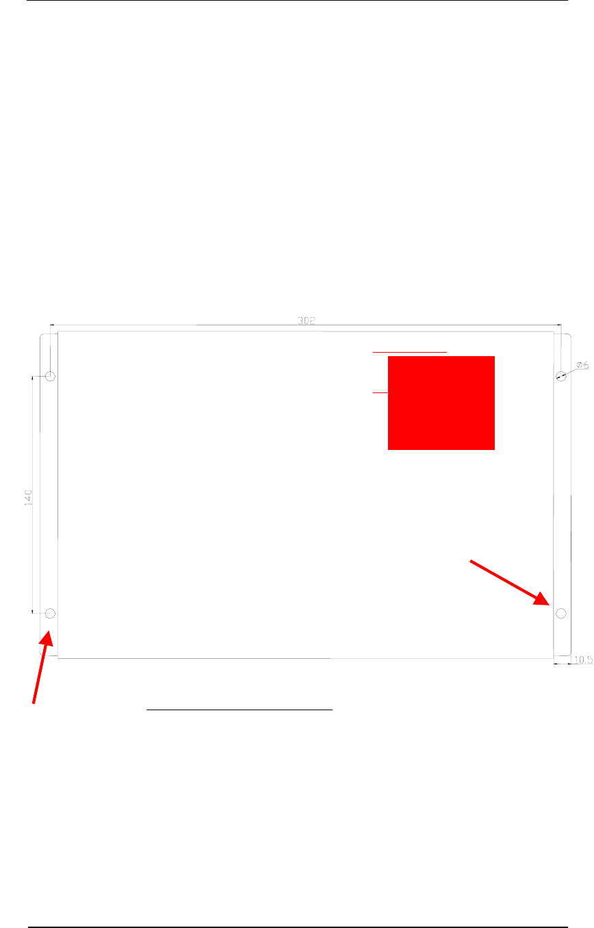
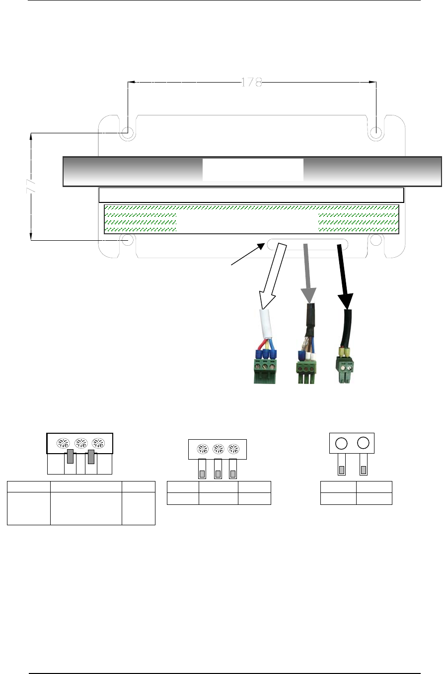
Premier Line Control Unit (PLCU) Dimensions
(All dimensions are in millimeters)
Premier Guard Installation Manual
5
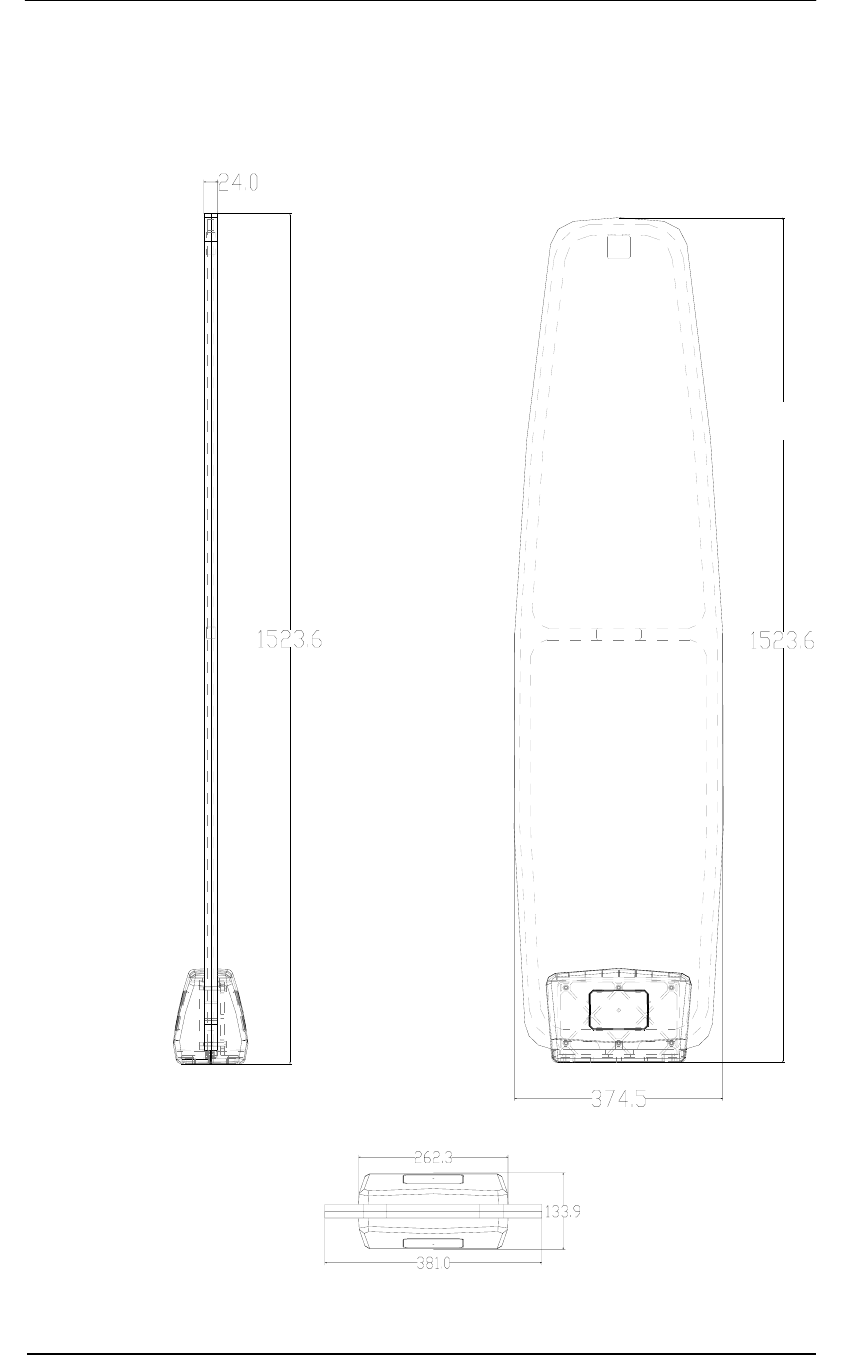
Premier Guard Pedestal Dimensions
(All dimensions are in millimeters)
Front View
Side View
Pedestal Base

Premier Guard Installation Manual
6
Premier Guard Base Footprint Dimensions
(All dimensions are in millimeters)
4-R6
Premier Guard Installation Manual
7
Connection Diagram
TX Control
Alarm & IR Remote
Control Display
Channel 2 Channel 1
LAN
Buzzer
24vac Input
Fuseholder
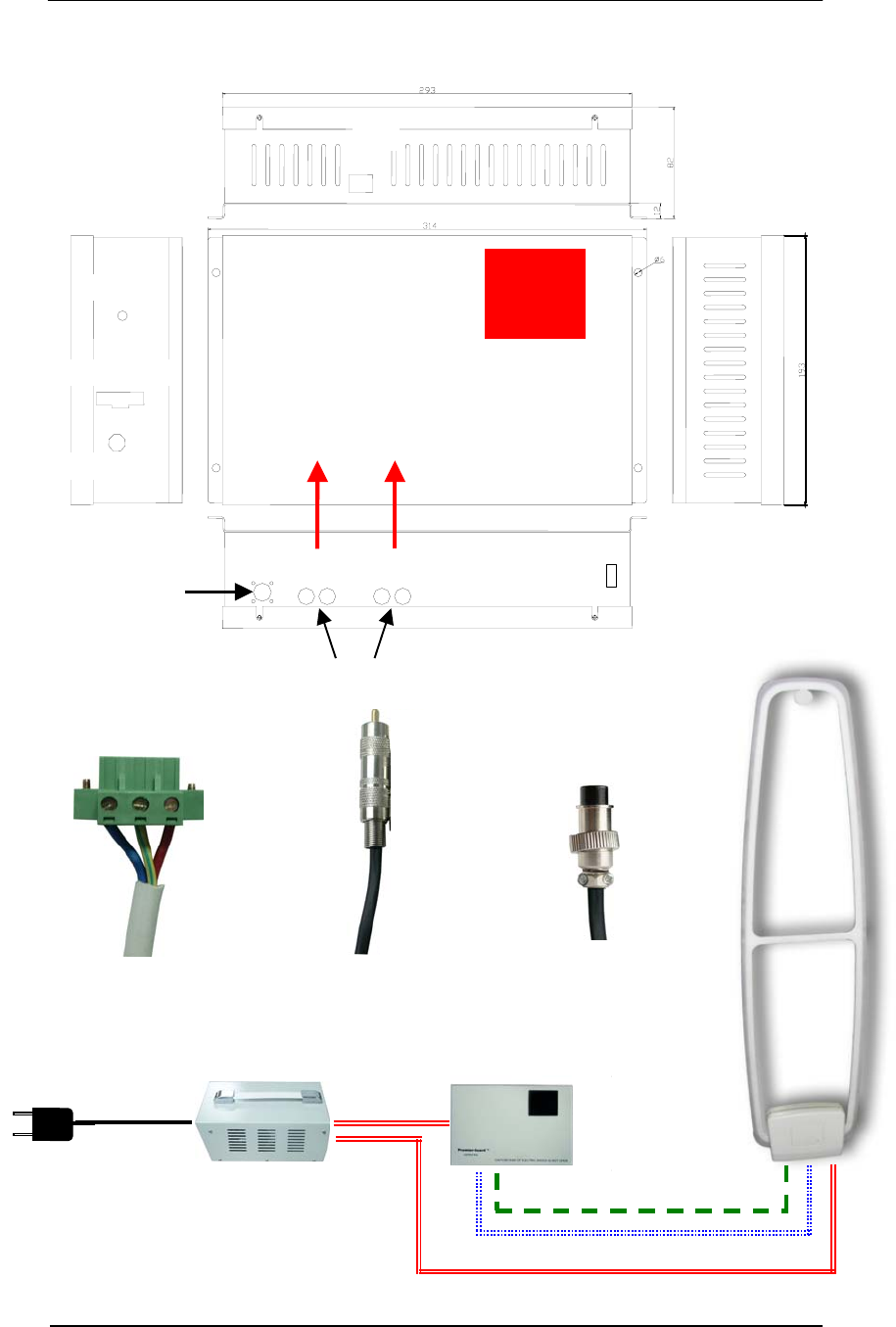
TX Control Sockets
RX Sockets
External Alarm Relay
RX-A&B
R
X
-
C&D
3-Pin Power
Connector (1)
RX
Connectors (1)
TX
Connector (1)
24vac
Power Cable
110/220vac
24vac Transformer RX Cable
24vac Power Cable

Premier Guard Installation Manual
8
INSTALLATION
Installation Site Power Supply Verification
It is STRONGLY RECOMMENDED THAT SOLID GROUNDING BE MAINTAINED FOR THE
POWER TRANSFORMER. Sometimes poor grounding and high noise from the power source
will adversely affect system sensitivity or detection range.
Parts List –Premier Guard System
Part Name Order Number
1. Premier Guard Transceiver WGPGTR58
2. Premier Line Control Unit WGPLCU58
3. Control Box Alarm Cover (TBD)
4. Remote Control (TBD)
5. Instruction Manual WG-PGTR58-IM
6. 24vac Transformer WGPS2490-1
Control Box
WGPLCU58
24vac Transformer
WGPS2490-1
Remote Control
WG-(TBD)
Transceiver
WGPGTR58
Premier Guard Installation Manual
9
Quick Start for System Connections
A Premier Guard system consists of a stepdown transformer, a Premier Line Control Unit
(PLCU) and a transceiver (antenna).
The transformer box has two 24vac outputs that can power both the PLCU and transceiver. A
single transformer box supports one PLCU and transceiver.
The PLCU is powered by the stepdown transformer via a single 24vac power input. The
PLCU has two types of connections for the transceiver. One is a transmit control signal
connector and the other s a receive signal connector. Both the TX and RX cables will connect
from the PLCU to the transceiver. The PLCU case is constructed to facilitate wall mounting.
Before permanently connecting the pedestal, place it at the location you intend to install it,
and then arrange the cables from the PLCU directly to the pedestal. You will have to remove
the pedestal base cover to connect the cables.
Additional installation procedures are shown in greater detail in the following sections.
Connections Legend
Power Bus
TX Control Signal
RX Signal
Premier Guard
Transceiver Antenna
24vac
24vac
Transforme
r
PLCU
110/220vac
24vac
Premier Guard Installation Manual
10
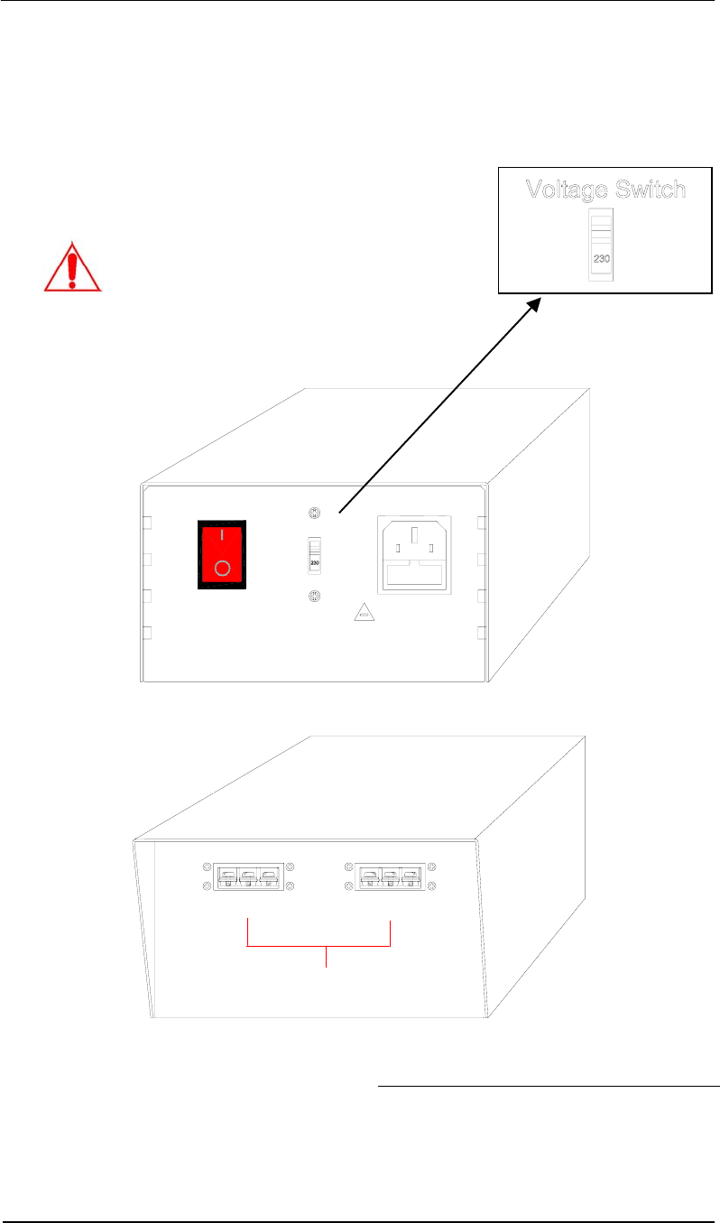
Transformer Box
The transformer box accepts two input voltages: 110vac in North America, 220vac in Europe.
Place the Voltage Switch in the proper position based on the incoming voltage (see picture
below). There are two 24vac outputs that can power both the PLCU and transceiver.
Transformer Cable Connection
Blue Wire
Yellow Wire with Green Stripe
Red Wire
0V
Gnd
24vac
Caution:
The Voltage Switch is used to set the
system for the appropriate AC input.
North America – Set the switch to 115.
Europe – Set the switch to 230.
Fuse replacement
Extend fuse (time-delay fuse)
5mmx20mm 3.15A
Equipment shall be electrically disconnected from
the branch-circuit supply when replacing the fuse.
WARNING - TO REDUCE THE RISK OF DAMAGE. REPLACE
ONLY WITH SAME TYPE AND RATING OF FUSE.
OFF
ON
VOLTAGE SWITCH
AC POWER
24VAC OUTPUT 2
0V GND 24V0V GND 24V
24VAC OUTPUT 1
Transformer Case
Back View
Transformer Case
Front View
A
s above picture shows, the transforme
r
box has two power sockets for the PLCU
and pedestal connectors. Each output
has a 3-pin terminal block. Pin outputs
are described on the table at the right.
Maximum Output: 4A in total
Premier Guard Installation Manual
11
Installing the PLCU
The PLCU has one TX Control Signal connector and four RX Signal connectors. Connection
to the transceiver is described in the following sections. The PLCU can be installed on the
wall via the integrated mounting bracket.
To mount the PLCU to the wall:
1. Using the mounting bracket as a template, mark four holes on the wall at the location you
intend to install it.
2. Drill holes into the wall and insert anchors or screws. Note: the mounting method must be
able to support 3.5kg (7.7 lbs).
3. Attach the mounting bracket to the wall. Screw it firmly to the wall with the proper screws.
Mounting Screw
Holes (4 places)
Mounting
Bracket
A
ll dimensions are in millimeters.
Suggested Mounting Information
1. Wallmount Holes – 4mm diameter
2. Wallmount Screws – 5x30mm self-tapping screws
with 8.2mm head.
Premier Guard Installation Manual
12
Connecting the Pedestal
Before the connecting the transceiver, place it at the location where you intend to install it,
and arrange the cables directly from the PLCU to the transceiver.
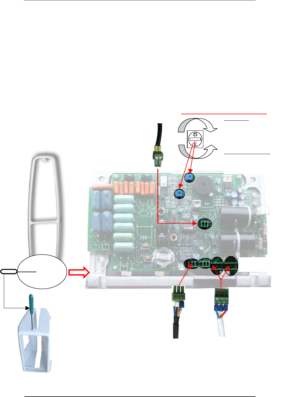
1. Remove the base cover of the pedestal to expose the transmitter board (picture below).
Note: Press down the top of base cover towards pedestal and LIFT the half case upward to
release the cover from the pedestal’s locking mechanism.
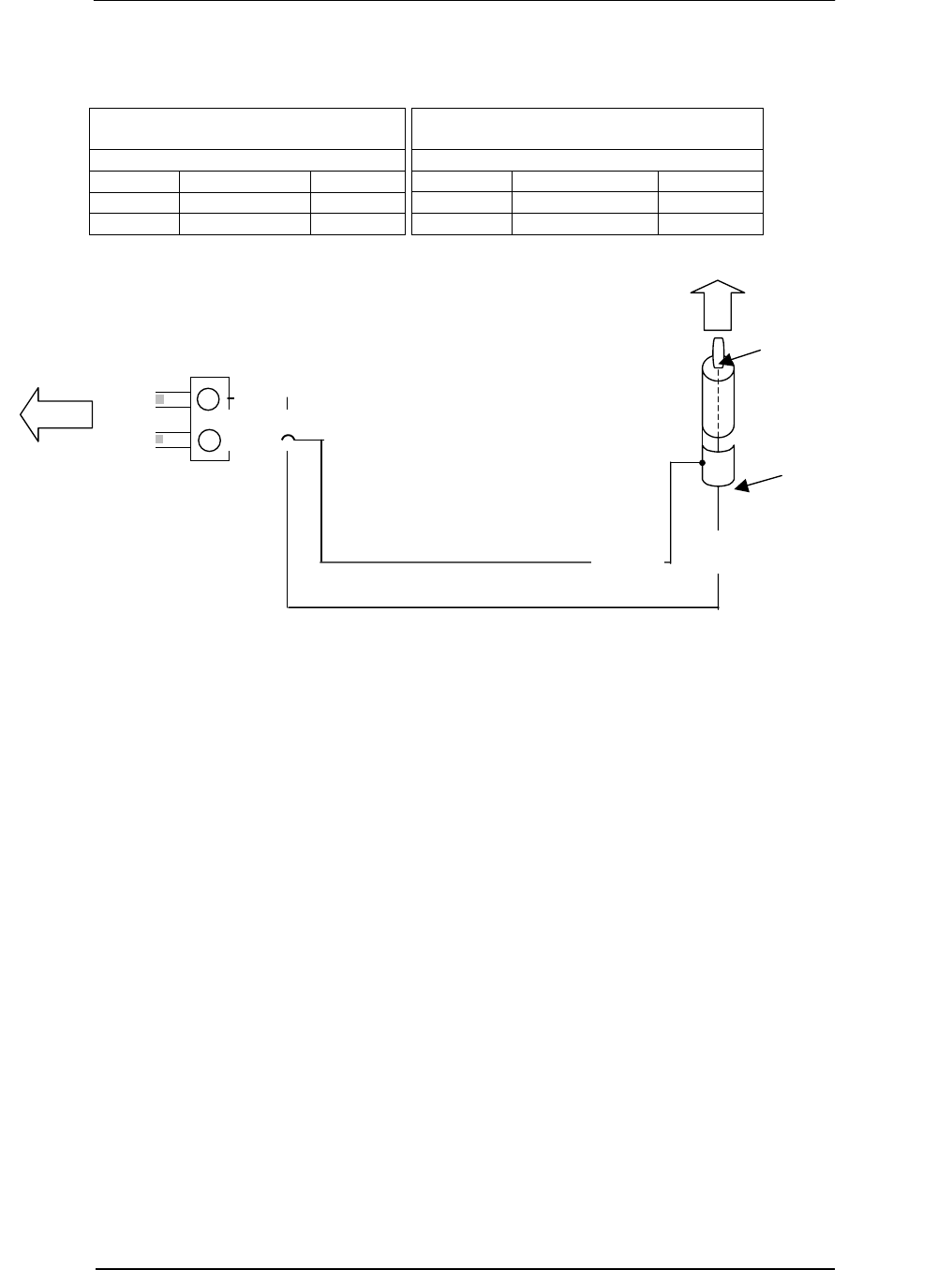
2. Loosen the screws to remove the cable wires from the connector. Feed the cable through
the slot of the aluminum base mounting plate, and then reconnect the cable wires to the
connector according to wire connection table.
3. Plug the three connectors (Power, Tx Signal and Rx Signal) onto the appropriate sockets
on the transmitter board (see picture below).
4. After completing all connections, firmly mount the pedestal base to the ground. (See
following page.)
5. Re-install the base cover.
From
Transformer
Box
Removing The Base
Use a screwdriver to punch
the cover at the hole. The
cover lock will release, and
then you can take apart the
two halves.
Power Sockets
(3 Pins)
Control Signal
Sockets (3 Pins)
RX Signal
Sockets
(
2 Pins
)
From PLCU
Either of the two
pedestal sockets
Clockwise
– increase sensitivity
– prone to false alarms
Counter-Clockwise
– decrease sensitivity
– less false alarms
Rx signal pre-process sensitivity
From PLCU
Premier Guard Installation Manual
13
(All dimensions are in millimeters.)
Cable Inlet Slot
Plexiglas Antenna
Transmitter Board
Top View of Pedestal
Note: To direct cables through the inlet
slot, first unscrew the cable wires from the
connectors and lead the cables through the
slot. Then re-attach the wires onto the
connector, following the correct pin
mappings noted on the connection tables
in the next few pages.
Left Middle Right
Red
(Brown)
24vac
Yellow
(Green Stripe)
GND
Blue
0v
Left Middle Right
GND Brown Blue
Left Right
Red Black
Connector for Power Connector for Control Signal Connector for RX Signal
Premier Guard Installation Manual
14
Cable and Connector Connections
1. Pedestal and Transformer Box Power Connection
The three pins from the transformer power connecter are connected to the corresponding
pedestal connector sockets. Pin color to each power connecters must be consistent.
Transformer Box Power Terminal Layout
(3 pins)
White Cable (3 wires)
Pin Function Color
Pin 1 0V Blue
Pin 2 Ground Green w/Yellow Stripe
Pin 3 24V Red(Brown)
When connecting the above pedestal power connectors, make sure the pin
order/color of the four power connectors is consistent. Do not transpose the
color order when connecting wires to connectors. Incorrect pin connection
will damage the system!
Pedestal Connector Layout
(3 pins)
White Cable (3 wires)
Pin Function Color
Pin 1 Blue
Pin 2 Green w/Yellow Stripe
Pin 3 Red(Brown)
The Power Terminal
on Transformer Box
24VAC O UTPUT
0V
GND
24V
Pin 1 Pin 2 Pin 3
Green with yellow stripe
Red (brown)
Blue
Pin 1
Pin 2
Pin 3
To pedestal 1
∩
∩
∩
Wire size is 20 AWG
Premier Guard Installation Manual
15
2. PLCU and Transformer Box Power Connection
Transformer Box Power Terminal Layout
(3 pins)
White Cable (3 wires)
Pin Function Color
Pin 1 0V/24V Blue/Red(brown)
Pin 2 Ground Green w/Yellow Stripe
Pin 3 24V/0V Red(brown)/Blue
(Power synchronization 180 degrees phase switch)
* Note: Pin 1 and Pin 3 of the transformer box terminal are equivalent to former N and L
terminals for 110/220vac systems. Switching them will switch the system’s phase 180
degrees; same as former 110/220vac systems.
PLCU Power Connector Layout
(3 pins)
White Cable (3 wires)
Pin Function Color
Pin 1 0V/24V Blue/Red(brown)
Pin 2 Ground Green w/Yellow Stripe
Pin 3 24V/0V Red(brown)/Blue
Red/brown
Green with yellow strip
Blue
Pin 1
24 VAC OUTPUT
Pin 1
Pin 2
Pin 3
Pin 2 Pin 3
24V
GND
0V
Wire size is 20 AWG
Transformer Box
Power Terminal
To PLCU
Premier Guard Installation Manual
16
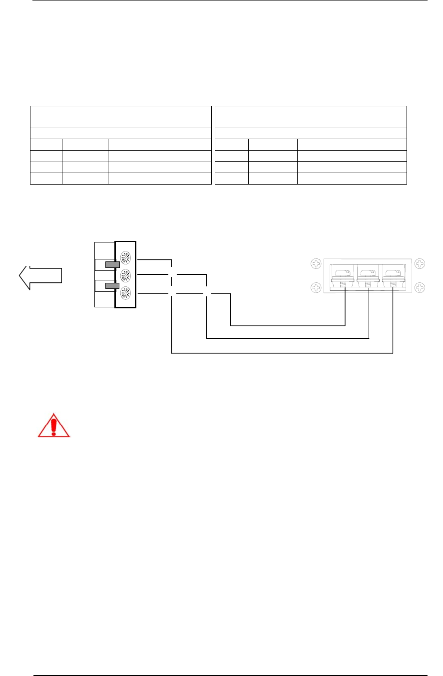
3. Pedestal and PLCU TX Control Signal Connection
PLCU TX Control Signal
Connector Layout
(3 pins)
Black Cable (3 wires)
Pin Function Color
Pin 1 Signal+ Blue
Pin 2 Signal- Brown
Pin 3 Shielding GND
Sockets connection note:
To ensure good contact and proper connection from the pedestal to the PLCU, make sure the
cable sockets are firmly connected and the pins are correctly aligned.
Pedestal TX Control Signal
Connector Layout
(3 pins)
Black Cable (3 wires)
Pin Function Color
Pin 1 Signal+ Blue
Pin 2 Signal- Brown
Pin 3 Shielding GND
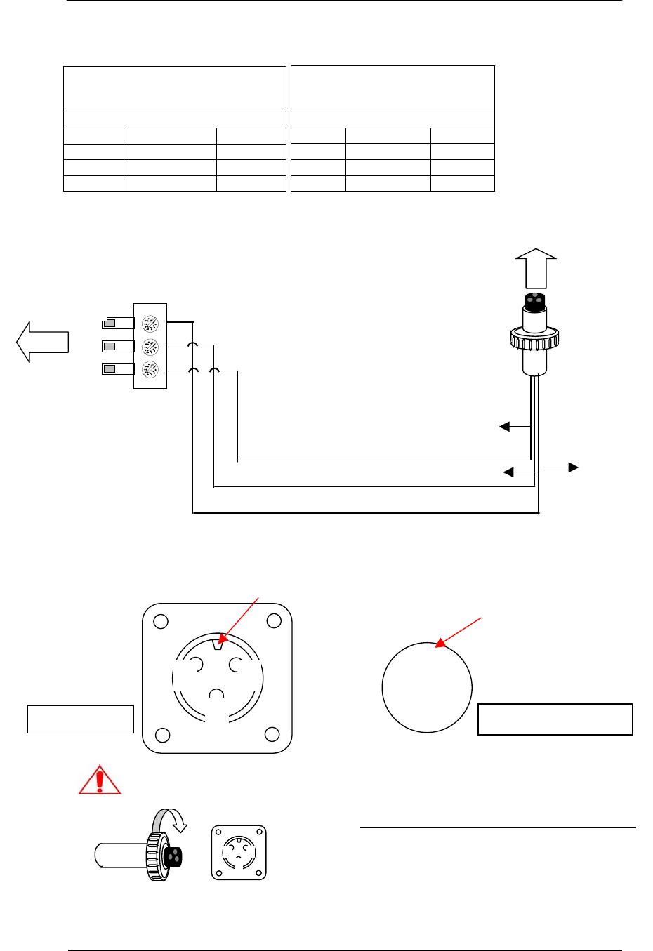
1 2
3
Aligning Key
PLCU Socket
2
1
3
Aligning Slot
TX Control Connector
Incorrect pin mapping and loose contact connections
will result in system malfunction!
Insert connector into socket, turn the
screw cap, lock and set.
Procedure
1. Ensure the aligning key mates to the aligning
slot,
2. Insert the TX control connector into the socket
of the PLCU.
3. Turn the screw cap according to the figure on
the left, then lock and set.
Pin 1
Pin 2
Pin 3
Pin 1 Blue
Pin 2 Brown Pin 3 Shield
To PLCU
To Pedestal
Wire size is 22 AWG, Shielded
Premier Guard Installation Manual
17
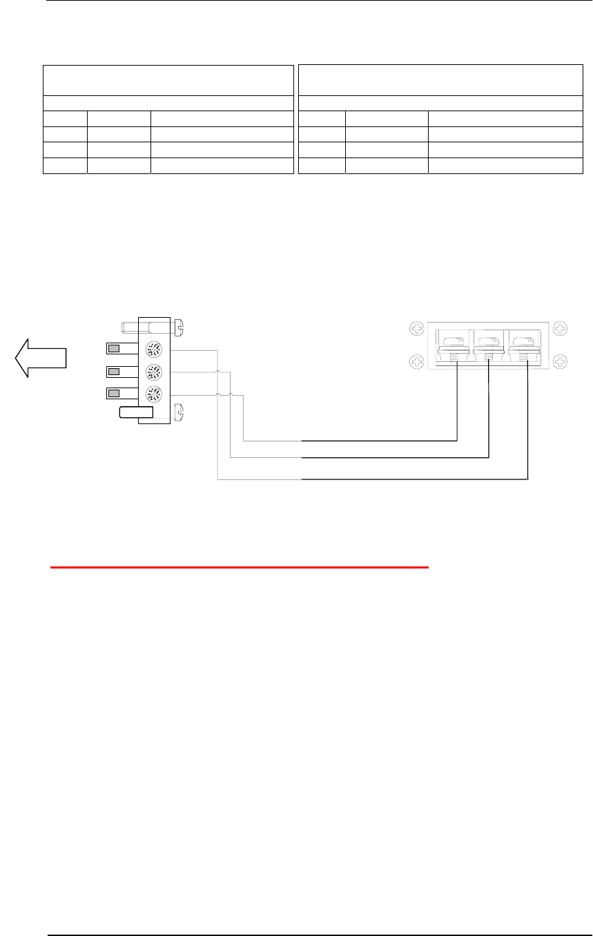
4. Pedestal and PLCU RX Signal Connection
Control Pack RX Signal Connector
Layout (2 pins)
Black Cable (2 wires)
Pin Function Color
Pin 1 Signal+ Black
Pin 2 Signal- Red
Pedestal RX Signal Connector
Layout (2 pins)
Black Cable (2 wires)
Pin Function Color
Pin 1 Signal+ Black
Pin 2 Signal- Red
Connector Shield
Connector Pin
Pin 1
Pin 2
Pin 1Pin 2
To PLCU
Red
Black
To Pedestal
Wire size is 22 AWG, Shielded
Premier Guard Installation Manual
18
Power Cord Notices
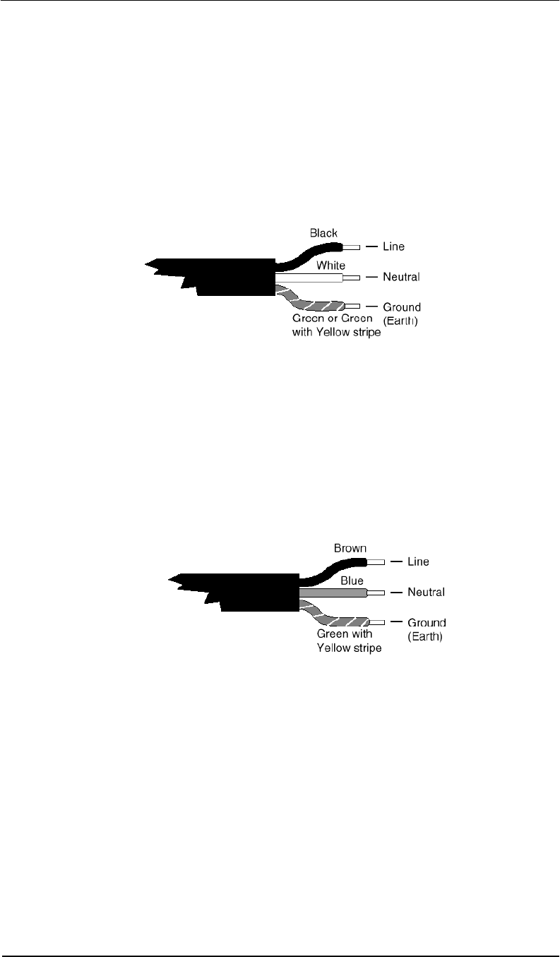
North American Power Supply Cords
This equipment is supplied with an external power line at one end and a molded
receptacle terminal block at the other end. Conductors are color coded white
(neutral), black (line) and green or green/yellow (ground).
Operation of this equipment at voltages exceeding 130vac will require power supply
cords that comply with NEMA configurations.
International Power Supply Cord
This equipment is supplied with an external power line at one end and a molded
receptacle terminal block at the other end. Conductors are CEE color-coded—light
blue (neutral), brown (line) and green/yellow (ground). Other IEC 320 C-13 type
power supply cords can be used if they comply with the safety regulations of the
country in which they are installed.
We recommend that you use a CE approved power cord H05 VV-F or H05 VVH2-F2
(Refer to the electrical code which governs your country for installation of an Anti-Theft
Unit to the main power supply)
Premier Guard Installation Manual
19
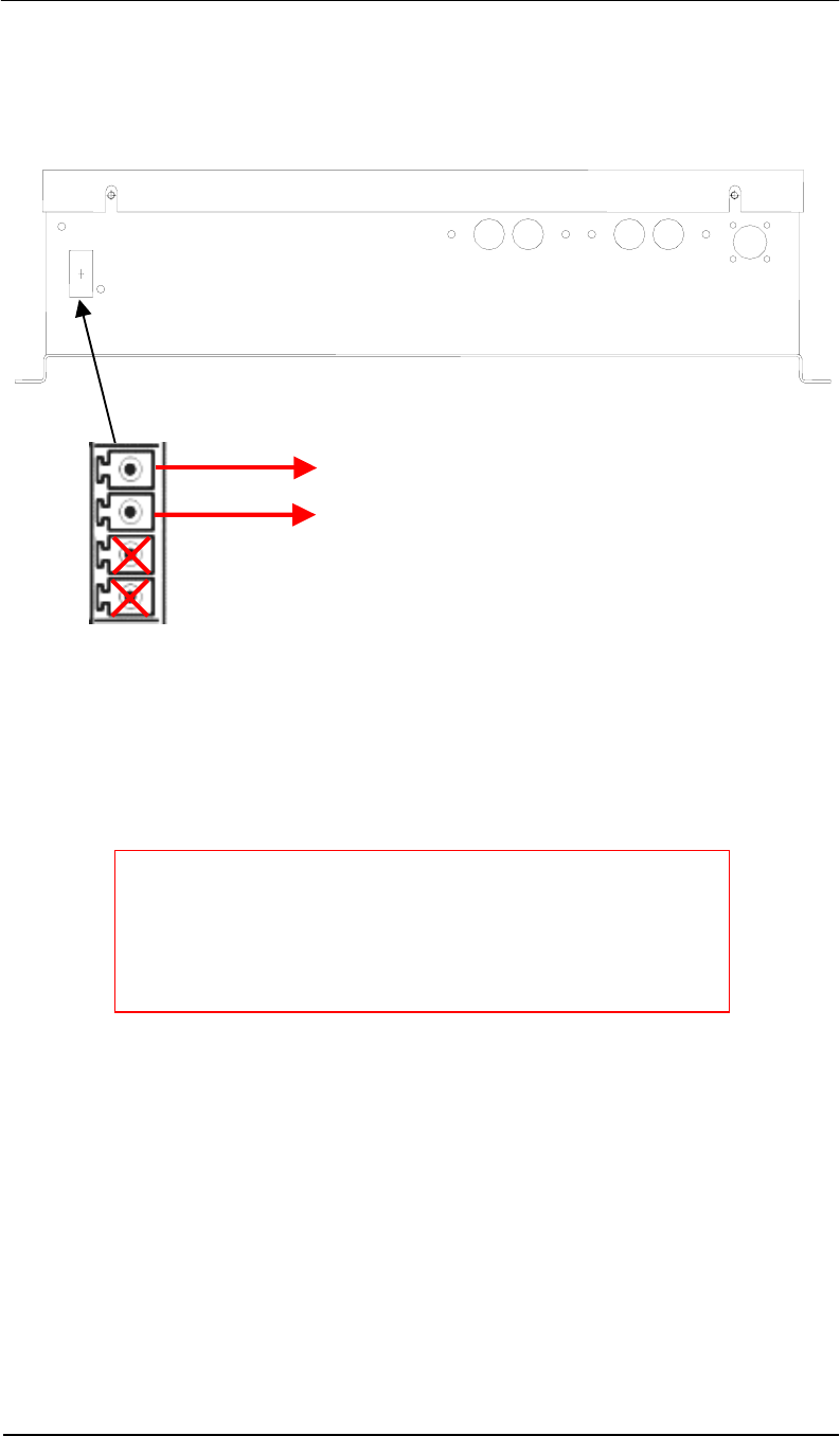
External Relay interface
The external relay interface is located at the side of the control unit case.
There is one external alarm relay located on the PLCU case. The relay switch is closed when
an alarm is triggered by the system. To connect the system to an external alarm, build a cable
with a matching 4-pin connector, and then insert the connector into the External Relay socket
on the PLCU. Ensure the cable firmly secured in place by the connector’s screws. The
External Relay switch has a rating of 1A@250vac/24vdc.
V
alid output terminals
To remote alarm
Suggested Relay Ratings
1A@250vac/24vdc
Notes:
1. Wire length to the dry contact circuit is limited to 20 feet.
2. To prevent high voltage noise from being introduced into
the transceiver and degrading the system’s performance,
it is highly recommended that you use a 24vdc output
relay.
RxA RxB RxC RxD Tx Control
External
Relay
Premier Guard Installation Manual
20
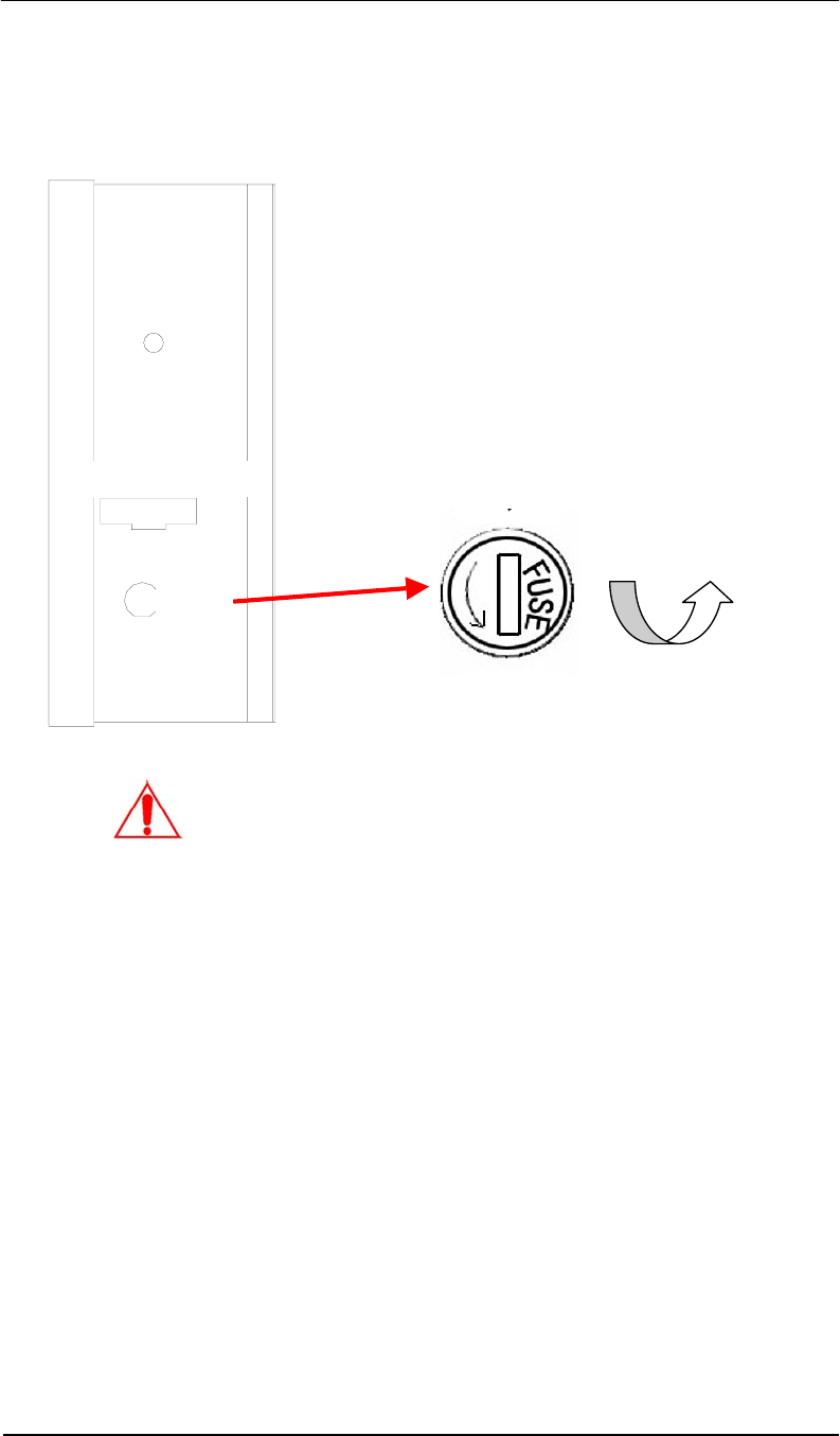
Fuse Replacement Information
The fuse holder is located on the control box side panel.
1. Equipment shall be electrically
disconnected from the branch-
circuit supply when replacing the
fuse.
2. Remove the fuse holder with a
screwdriver, rotating it in a
counterclockwise direction.
3. Replace the fuse in accordance
with the specification noted
below.
Fuse Replacement:
Extended Fuse (Time-Delay Fuse)
5mm x 20mm 24vac @ T3.15A/250V
WARNING
–
TO REDUCE THE RISK OF DAMAGE, REPLACE ONLY WITH
THE SAME FUSE TYPE AND RATING.
Counterclockwise
Power 24Vac
Fuse
Premier Guard Installation Manual
21
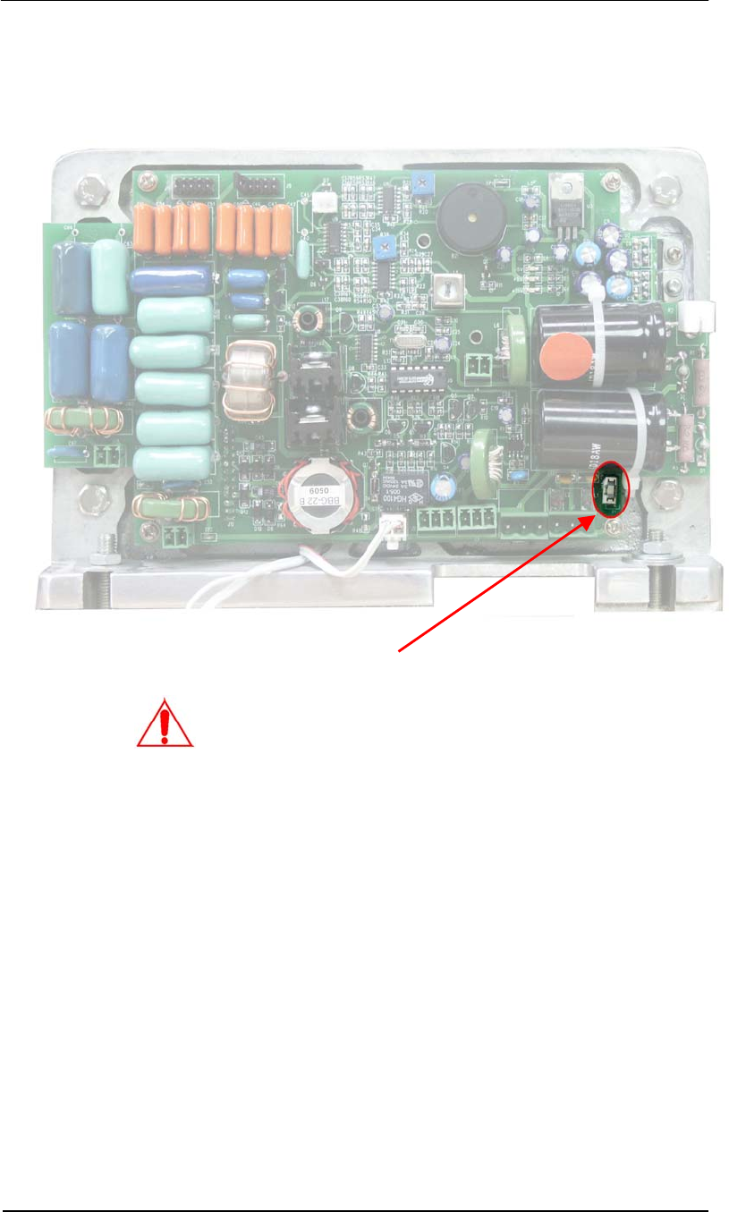
Control Unit Fuse Replacement
WARNING – TO REDUCE THE RISK OF DAMAGE, REPLACE ONLY WITH THE SAME
FUSE TYPE AND RATING.
Transmitter Board – Top View
Primary Input Fuse
Fuse Replacement:
Slow Blow Fuse
SMT Type
24vac @ T3A/250V Fuse
Premier Guard Installation Manual
22
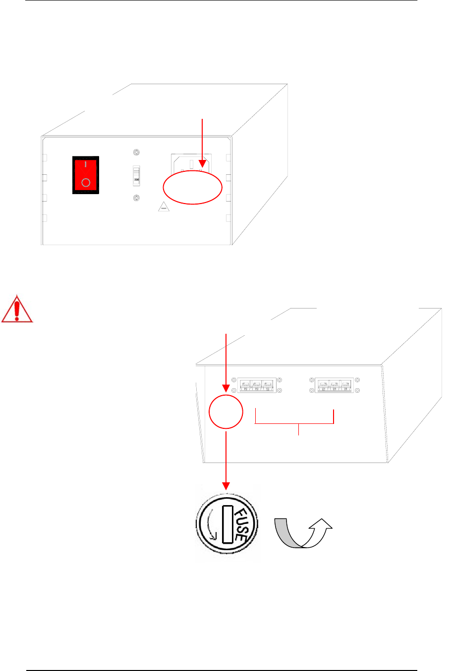
Power Supply Fuse Replacement
WARNING – TO REDUCE THE RISK OF DAMAGE, REPLACE ONLY WITH THE SAME
FUSE TYPE AND RATING.
Fuse replacement
Extend fuse (time-delay fuse)
5mmx20mm 3.15A
Equipment shall be electrically disconnected from
the branch-circuit supply when replacing the fuse.
WARNING - TO REDUCE THE RISK OF DAMAGE. REPLACE
ONLY WITH SAME TYPE AND RATING OF FUSE.
OFF
ON
VOLTAGE SWITCH
AC POWER
Primary Input Fuse
24VAC OUTPUT 2
0V GND 24V0V GND 24V
24VAC OUTPUT 1
Secondary Output Fuse
Transformer Case
Rear View
Maximum Output: 4A Total
Fuse Replacement:
Slow Blow Fuse
5mm x 20mm
Primary Input
110vac @ T3.15A/250V (USA)
220vac @ T1.6A/250V (Europe)
Secondary Output
24vac @ T4A/250V
Counterclockwise
Transformer Case
Front View
1. Equipment shall be electrically
disconnected from the branch
circuit supply when replacing the
fuse.
2. Remove the fuseholder from the
main AC input socket with pliers,
then remove the fuse out of the
fuseholder.
3. Replace the fuse in accordance
with the specifications noted
below, then insert the fuseholder
back into the AC input socket.
4. Equipment shall be electrically
disconnected from the branch
circuit supply when replacing the
fuse.
5. Remove the fuseholder with a
screwdriver, rotating it in a
counterclockwise direction.
6. Replace the fuse in accordance
with the noted specifications.
Premier Guard Installation Manual
23
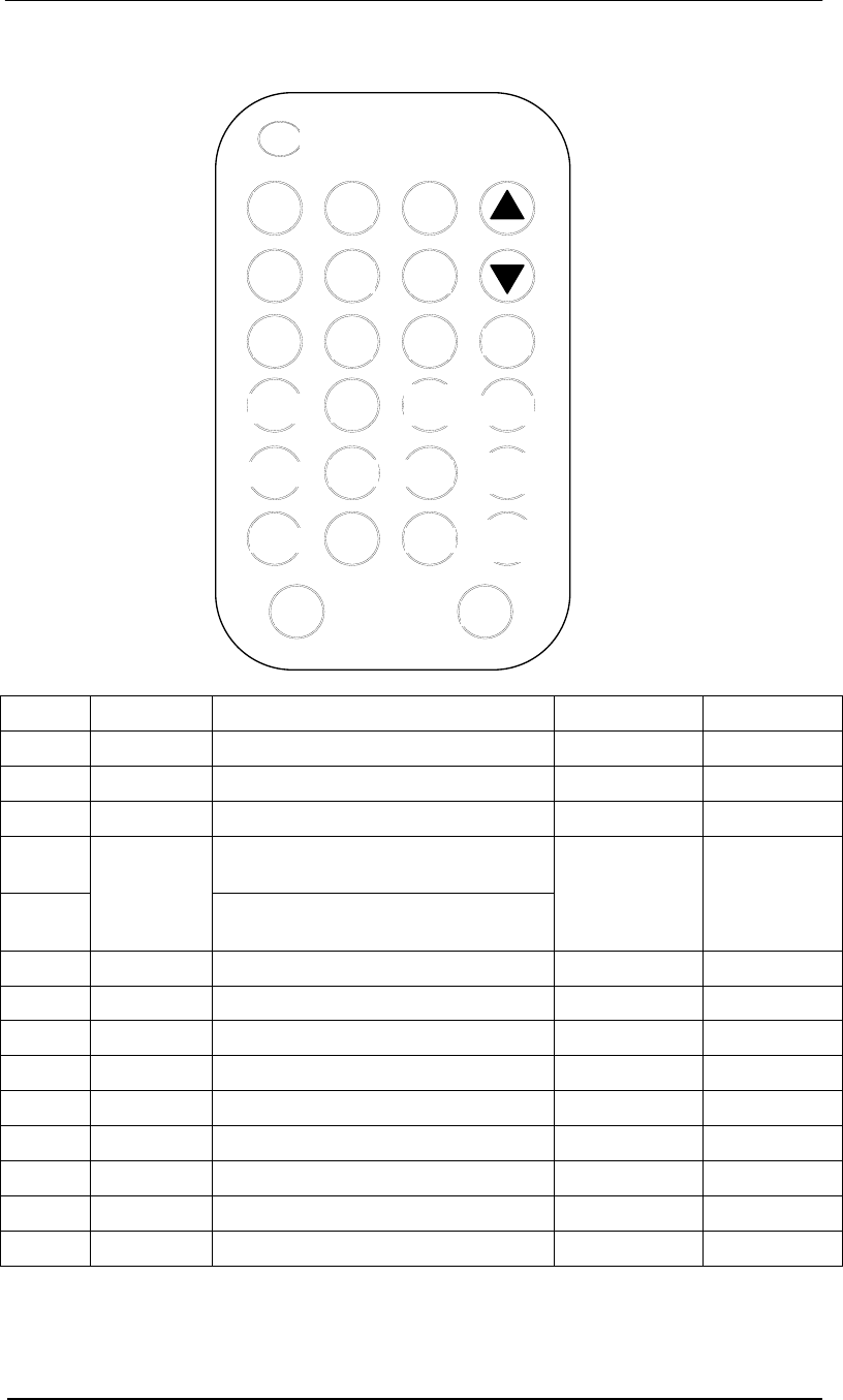
IR Remote Control Keypad Description
Key ID Button Parameters Description Default Value Valid Range
A GN Gain Adjustment 1 0, 1
B SYN Sync Adjustment 1 0 to 250
C RE Receiving Window Delay 8 0 to 14
H1 Minimum signal adjustment for
antenna Channel 1
H2
MIN
Minimum signal adjustment for
antenna Channel 2
40
0 to 999
(Practical
range 0-200)
D NSE Noise Display (4 channels) 0 0 to 2
F TX OFF Turn off transmitter 1 0 to 1
E DFT Return to default settings 0 0 to 1
P PC Password change 689 (see note) 0 to 999
G ARM OFF Turn off alarm sound 1 0 to 1
L ARM RST Alarm count reset 0 0 to 1
S SA Save the parameters to Flash ROM NA NA
CON Confirm the parameters input NA NA
EX Exit NA NA
Note: Default password is 689. After changing, the system will use the new password
as default. The new password will remain saved at power off. THIS IS A NON-
RECOVERABLE ACTION. KEEP THE NEW PASSWORD IN A SAFE LOCATION IN CASE
YOU FORGET IT.
PC
PSW
1 2 3
4 5 6
7 8 9
0
CON TX
OFF
MIN1
DFT
MIN2
GN SYN
A
RM
OFF
RE NSE
A
RM
RST
SA EX

Premier Guard Installation Manual
24
Tuning Procedures & Tips
There are mainly two problems that affect system’s functioning and
performance. One is that system picks up tags and labels poorly. The other is
that system false alarms (or causes other system to do so) without tags or
labels in detection zone.
Low Pick up Rate
1. Check noise “D” (ranging from 0-
999, >100 or so is big noise & >400
is heavy noise).
2. Adjust MIN, GN & RE to increase
sensitivity (see diagram below).
3. Adjust POT for Rx signal pre-
process sensitivity on TX board (see
page 18).
4. Shorten pedestal separation or use
stronger tags (e.g. Super Pencil).
Interference with or by other
systems
1. Swap L & N terminals on power plug
of control pack.
2. Adjust SYN “B” step by step to align
up with other systems.
Please open and tune the systems one by one if there are multiple systems
installed. It will help determine which system is causing the problem.
PROBLEMS
SOLUTIONS
The diagram below explains how the major three tuning parameters influence
system performance.
Default 1
200
RE
Default 8
GN
MIN
Default 40
014
0
Decrease Sensitivity,
shorter detection range,
but prone to instability.
Increase Sensitivit
y
but tendency to
false alarm.
0
Counter Clockwise
POT
Clockwise
Premier Guard Installation Manual
25
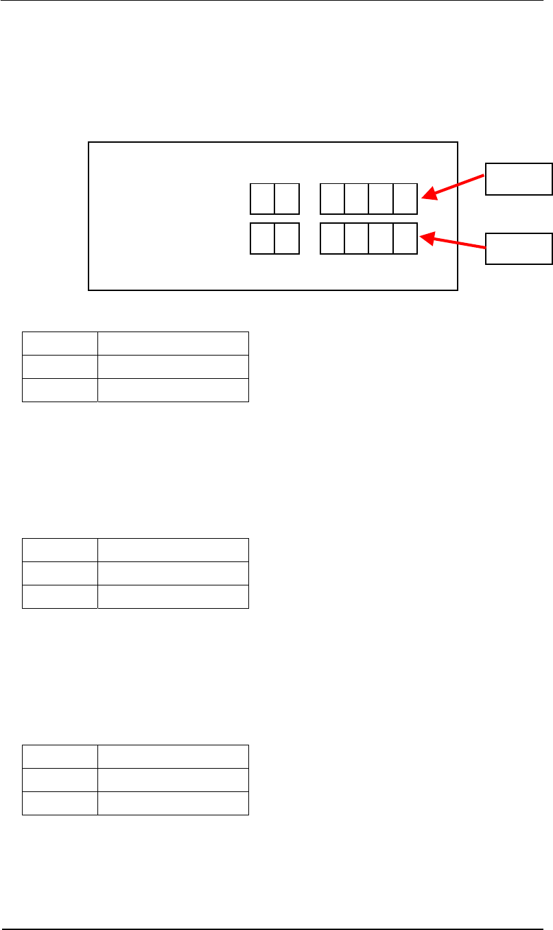
Remote Control Programming
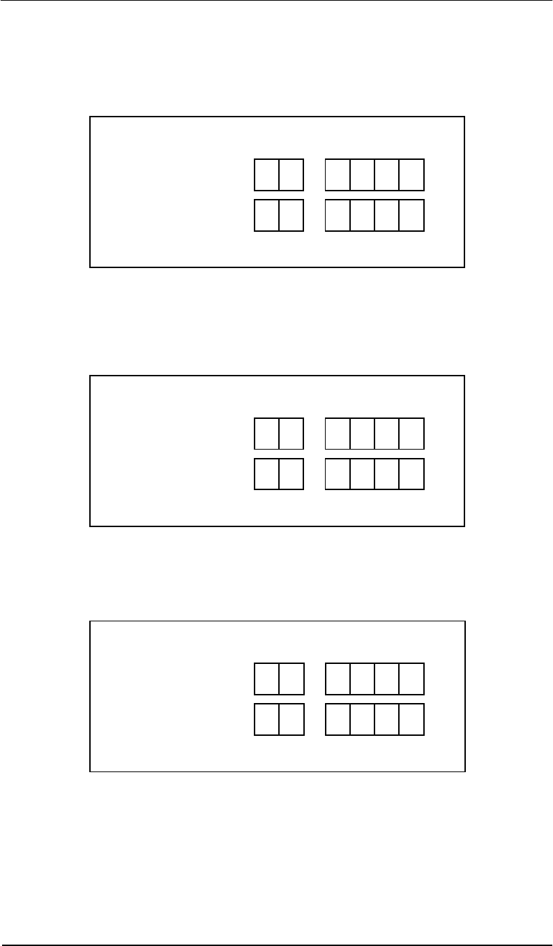
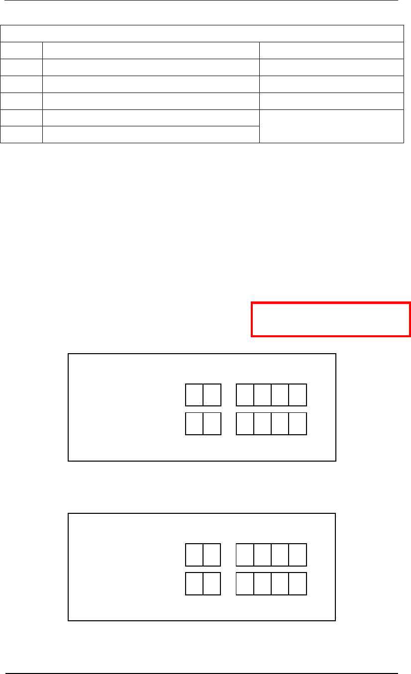
Without receiving remote control signals, the panel displays the alarm count, indicating the
number of times the system has alarmed. See Figure 1.
Figure 1. Alarm Count
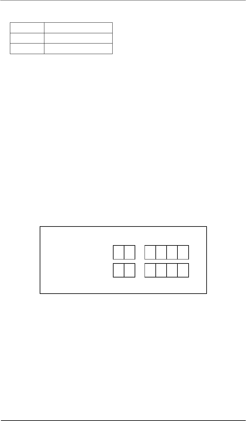
Press [PSW] button to open the remote control, then enter the password. The default
password, if not previously changed, is 689.
Figure 2. Display after [PSW] is Pressed
Input Password 689 and press [CON] to confirm/accept the password.
01
0
0 6 98
Premier Guard Installation Manual
26
Note: Inputting the wrong password will cause an error message to be displayed as
per the following picture. After three successive times of inputting an incorrect
password, the remote will be disabled. You will need to turn system power off/on and
input the password again.
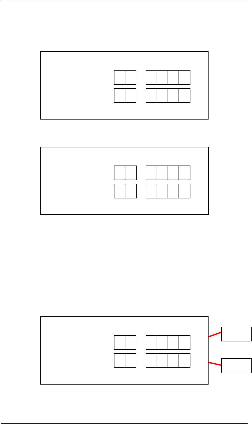
When the correct password is verified, the panel will display the following and is now ready for
receiving configuration inputs.
There are three basic steps to inputting a programming parameter:
• Press function button.
• Input parameter number.
• Press [CON] to accept the parameter.
After parameter confirmation, the panel will display the tag window signal. If there is no tag in
the detection zone, the value reflects the noise level in the receiving window without a tag.
The upper value reflects the signal level in the tag window from antenna channel 1. The lower
value reflects the signal level in the tag window from antenna channel 2. (See NSE noise
display entry; it’s the same value with D1)
CH 1
CH 2
0 E rr
-
94
- 13
Premier Guard Installation Manual
27
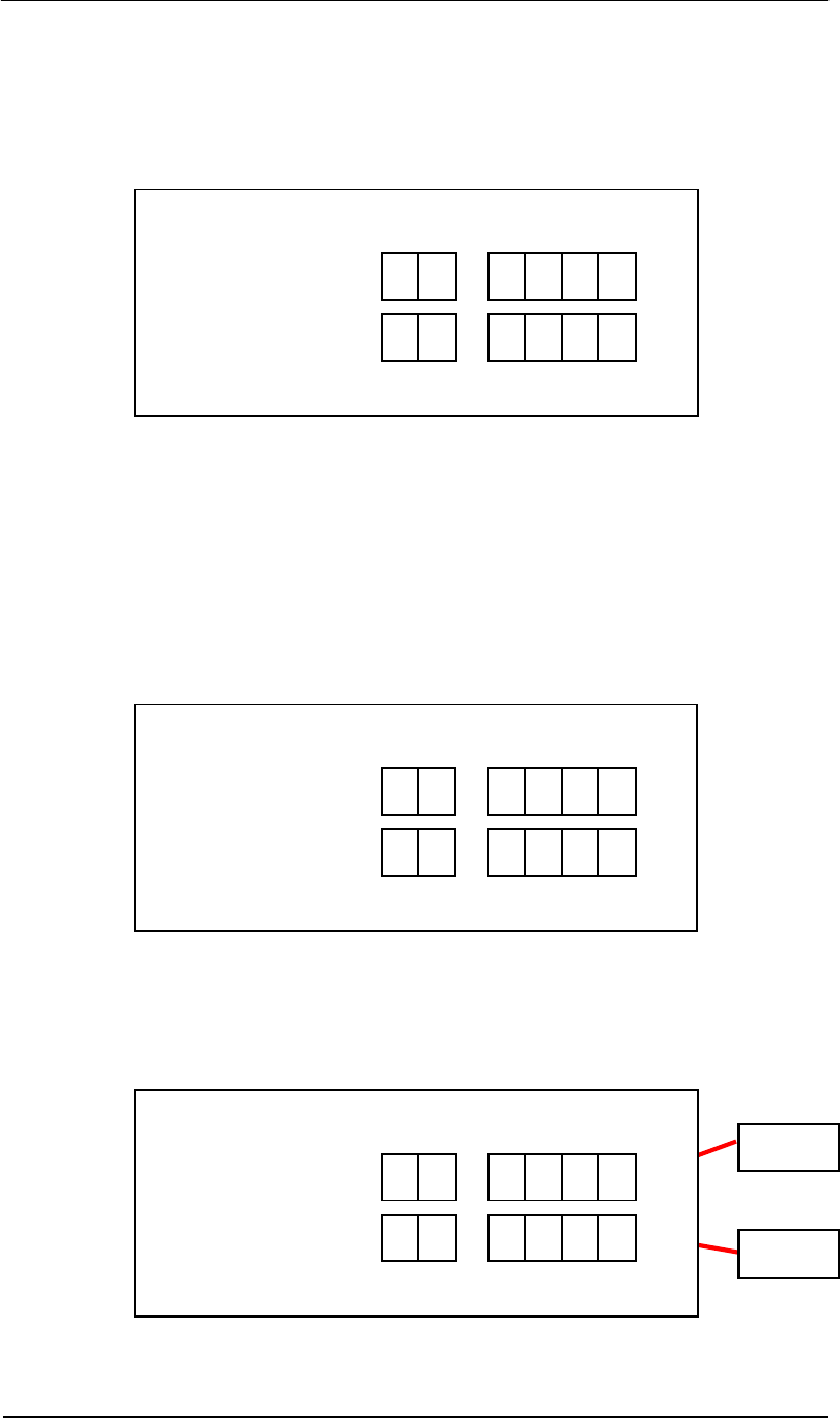
Key ID A: Gain Adjustment (Range: 0-1)
• Press [GN] – panel displays as per Figure 3.
• Input parameter number.
• Press [CON] to accept the parameter.
Figure 3.
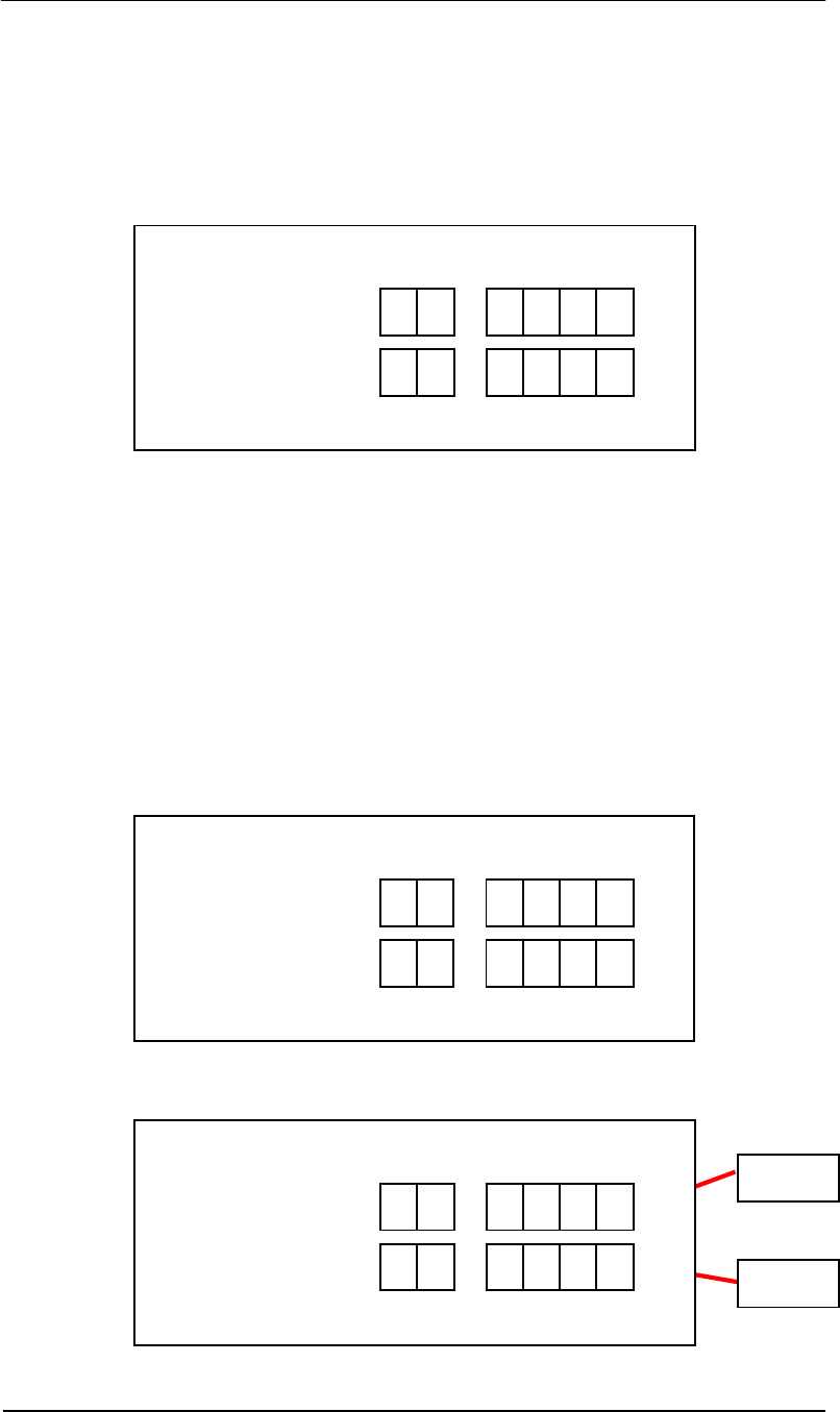
Key ID B: Sync Adjustment (Range: 0-250; increment: 1)
This sets the time from zero crossing point to the start point of transmitting burst. It is
important to eliminate crosstalk between different systems. Setting the default value to b-1 will
in most cases not interfere with other AM products.
• Press [SYN] – panel displays as per Figure 4.1.
• Input parameter number.
• Press [CON] to view the nose conditions. Display will be as per Figure 4.2.
Figure 4.1
Under this entry, you can also see the different noise condition (from the light segment display
and number indicator) at a different phase when the adjustment is applied. It will help you
select a relatively “clean” phase environment for the system.
Figure 4.2
CH 1
CH 2
A 1
b 1
13
- 74
Premier Guard Installation Manual
28
Key ID C: Receiving Window Delay (Range: 0-14; increment: 1)
You can input a number from 1-14. The larger the number, the later the receiving window will
be opened.
• Press [RE] – panel displays as per Figure 5.
• Input the parameter number.
• Press [CON] to accept the parameter.
Figure 5.
Key ID D: Noise Condition Display (Range: 0-4)
There are 6 noise level channels displaying different noise types from the two antenna
channels. The noise value range is 0 to 999. Usually any noise larger than 100 will be
considered as heavy noise. See details in the next table.
Note: If the noise condition display is open, the alarm will be deactivated unless you
input 0 to shut down the display.
• Press [NSE] – panel displays as per Figure 6.1.
• Input the parameter number.
• Press [CON] to accept the parameter – panel displays as per Figure 6.2.
Figure 6.1
Figure 6.2
CH 1
CH 2
C 4
d 4
94
- 13
Premier Guard Installation Manual
29
Noise Condition Display Configuration Table
Value Function Description Detection Purpose
0 Shut down tag or noise window display.
D1 Tag window display for channel one. Detect tag entering vertically.
D2 Tag window display for channel two. Detect tag entering horizontally.
D3 Average noise window display for channel one.
D4 Average noise window display for channel two.
Monitor average noise.
Note: The average noise level (D3 & D4) is also weighted by the Minimum Signal
Adjustment value. Therefore, if MIN (H value) is increased to be larger than the average
noise level, D3 or D4 will only show the H value instead of the average noise value.
Key ID H: Minimum signal Adjustment (Suggested increment: 20; practical range: 0-200)
Decreasing this number will increase system sensitivity but also at the risk of false alarming.
Vice versa, increasing the value will lower system sensitivity to avoid false alarms caused by
uncontrollable environment noise. There is also an auxiliary POT for RX signal pre-
process sensitivity adjustment (see page 18 and Addendum 1).
There are two antenna channels. Channel 1 is related to vertical orientation and Channel 2 is
related to horizontal orientation. H1 (MIN1) sets the minimum signal of Channel 1, and H2
(MIN2) sets the minimum signal of Channel 2.
• Press [MIN] – panel displays as per Figure 7.
• Input the parameter number.
• Press [CON] to accept the parameter.
Figure 7.1. Antenna Channel 1
Figure 7.2. Antenna Channel 2
H 1 04
H 2 04
Note: See Addendum 1 for
additional tuning instructions.
Premier Guard Installation Manual
30
After confirmation of H1 or H2 values, the panel will display the average noise level weighted
by the minimum signal adjustment for both antenna channels as follows. (See NSE noise
display entry. It’s the same value with D3, D4)
D3 reflects the average noise level weighted by H1 (MIN1) in antenna channel 1.
D4 reflects the average noise value weighted by H2 (MIN2) in antenna channel 2.
Key ID F: TX Off (Default value: 1; valid range: 0-1)
Value Action
0 Turn off Tx
1 Turn on Tx
• Press [TX OFF]
• Input the parameter number.
• Press [CON] to accept the parameter.
Input 0 will turn down the transmitting burst via software control. If system power is reapplied,
the system will return to default state of 1.
Key ID G: Alarm Sound Off (Default value: 1; valid range: 0-1)
Value Action
0 Turn off alarm sound.
1 Turn on alarm sound.
• Press [ARM OFF]
• Input the parameter number.
• Press [CON] to accept the parameter.
Input 0 will turn down the alarm sound via software control. If system power is reapplied, the
system will return to default state of 1.
Key ID L: Alarm Count Reset (Default value: 0; valid range: 0-1)
Value Action
0 Initial state.
1 Reset alarm count.
• Press [ARM OFF]
• Input the parameter number.
• Press [CON] to accept the parameter.
Input 1 will reset the alarm count to 0.
CH 1
CH 2
94
- 13
Premier Guard Installation Manual
31
Key ID E: Load Default Settings (Default value: 0; valid range: 0-1)
Value Action
0 Initial state.
1 Load default settings.
Input 1 will load default settings. See Default Parameters Table.
Key ID P: Password Change (Default value: 689; valid range: 0-999)
You can input customer-defined passwords with this entry. Press [CON] button after inputting
to activate the new password.
Note: Please SAFEGUARD the new password if you have changed from the default.
Once the new password is activated, the system will no longer recognize the 689
default password.
Key ID EX: Exit
Press [EX] to return to the alarm counter display status.
Key ID SA: Save
This button will save all current parameters to flash ROM and are saved, even after power
shutdown. When the system is rebooted, it will load all previously saved parameters from
flash ROM.
• Press [SA] – panel displays as per Figure 8.
• Input 1
• Press [CON] to accept the current parameters.
Figure 8.
5 1

Premier Guard Installation Manual
32
Premier Guard Installation Manual
33
Addendum 1
Pedestal Sensitivity Adjustment Guide
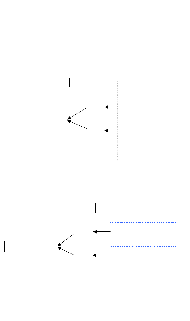
1. Two Methods to Adjust Sensitivity
There are two ways to adjust system sensitivity, and each method has a different effect on the
system.
A. Handheld Remote – Change the value of H (Minimum Signal Adjustment) at the PLCU
using the handheld remote (Ref pages 27).
B. POT Adjustment – Tune the antenna coils by adjusting the potentiometers on the
transmitter board located inside the pedestal base (Ref page 12).
A. Handheld Remote
Control Box
Receiver Board
in Control Box
H1
H2
B. Pot Adjustment
Loop Coil or Figure-8 Coil
Transmitter Board
POT 1
POT 2
Pedestal Antenna Coil Set
Loop Coil or Figure-8 Coil
Pedestal Connected to
RXA & RXB
Affected Pedestal
Pedestal Connected to
RXA & RXB
Note: Because sub-ports RXA/RXB are mapped into Channel 1 (H1 controlled) and
RXC/RXD are mapped into Channel 2 (H2 controlled), adjustment of either H1 or H2
will affect both of the mapped sub-ports (RXA/RXB or RXC/RXD), thus affecting the
pedestal(s) connected to the mapped sub-ports.
Premier Guard Installation Manual
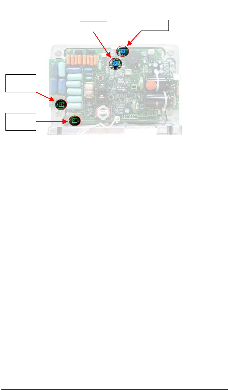
34
The tuning POTs only affect a single pedestal. Depending on the specific model of Premier or
Plus Line product, the specific POT (1 or 2) will affect a different antenna coil set:
a. POT 1 corresponds to the Figure-8 Coil (vertical orientation) and POT 2 corresponds
to the Loop Coil (horizontal orientation);
-- or --
b. POT 1 corresponds to the Loop Coil and POT 2 corresponds to the Figure-8 Coil.
c. POT 1 corresponds to the Loop Coil and POT 2 corresponds to ferrite rod antennas.
Note: “Figure-8” and “Loop” are names that identify the two antenna coils inside the pedestal.
The Figure-8 Antenna Coil detects vertical orientation signals and the Loop Antenna Coil
detects horizontal orientation signals.
***
Antenna
Socket 1
Antenna
Socket 2
POT 1
POT 2