WILLIAMS Furnace/Heater, Gas Manual L0408178
User Manual: WILLIAMS WILLIAMS Furnace/Heater, Gas Manual WILLIAMS Furnace/Heater, Gas Owner's Manual, WILLIAMS Furnace/Heater, Gas installation guides
Open the PDF directly: View PDF ![]() .
.
Page Count: 48
INSTALLATION & OPERATING
INSTRUCTION MANUAL
owners
manual
MODEL NOS.
4007332
4007732
5507332
6257732
FOR USE WITH
NATURAL GAS ONLY
MODEL NOS.
4007331
4007731
5507331
6257731
FOR USE WITH
LIQUEFIED
PETROLEUM (L.P.)
GAS ONLY
Save This Manual For
Future Reference.
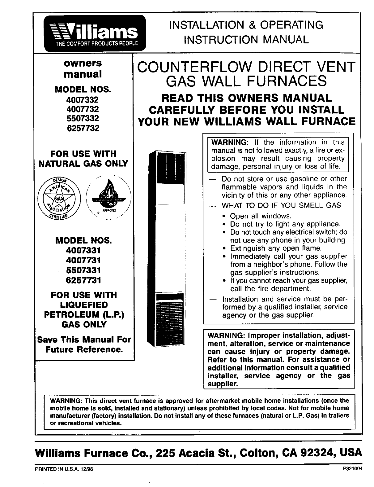
COUNTERFLOW DIRECT VENT
GAS WALL FURNACES
READ THIS OWNERS MANUAL
CAREFULLY BEFORE YOU INSTALL
YOUR NEW WILLIAMS WALL FURNACE
WARNING: If the information in this
manual is not followed exactly, a fire or ex-
plosion may result causing property
damage, personal injury or loss of life.
-- Do not store or use gasoline or other
flammable vapors and liquids in the
vicinity of this or any other appliance.
WHAT TO DO IF YOU SMELL GAS
• Open all windows.
• Do not try to light any appliance.
• Do not touch any electrical switch; do
not use any phone in your building.
• Extinguish any open flame.
• Immediately call your gas supplier
from a neighbor's phone. Follow the
gas supplier's instructions.
• If you cannot reach your gas supplier,
call the fire department.
Installation and service must be per-
formed by a qualified installer, service
agency or the gas supplier.
WARNING: Improper installation, adjust-
ment, alteration, service or maintenance
can cause injury or property damage.
Refer to this manual. For assistance or
additional information consult a qualified
installer, service agency or the gas
supplier.
WARNING: This direct vent furnace is approved for aftermarket mobile home installations (once the
mobile home is sold, installed and stationary) unless prohibited by local codes. Not for mobile home
manufacturer (factory) installation. Do not install any of these furnaces (natural or L.P. Gas) in trailers
or recreational vehicles.
Williams Furnace Co., 225 Acacia St., Colton, CA 92324, USA
PRINTED IN U.S.A. 12/98 P321004

Contents
Your Williams Warranty ......................... 2
Introduction .................................. 3
Basic Description .............................. 3
Optional Accessories ........................... 3
Helpful Installation Information ................... 3
Safety Rules ................................. 4
Unpack Your Furnace .......................... 5
Basic Tools Needed ............................ 5
Basic Materials ............................... 5
Installing Your Wall Furnace ..................... 6
Locating Wall Furnace and Thermostat .......... 6-7
Recessed Mount Installation ................. 7-9
Surface Mount installation .................. 9-10
Thermostat Installation ..................... 11-12
Vent Installation .......................... 12-13
Mounting Your Furnace ..................... 14-15
Gas Supply and Piping ...................... 15-16
Electrical Wiring ............................. 17
Start Up Procedure ........................... 18
Operating Your Furnace ..................... 19-24
How To Care For Your Furnace ............... 25-26
Furnace Technical Information .................. 26
Wiring Diagrams ........................... 27-28
TROUBLESHOOTING CHART ............... 29-34
Repair Parts .............................. 35-44
SERVICE HINTS ...................... Back Cover
How To Order Repair Parts ............. Back Cover
Your Warranty
The Manufacturer, Wilflams Furnace Co, warrants this wa_l furnace or heater to the original purchaser under the following conditions:
LIMITED ONE-YEAR WARRANTY
1Any part thereof which proves to be defective in material or workmanship within one year from date of original purchase for use will be repaired or replaced at the
Manufacturer's option. FOB its factory.
2 No liability is assumed by the Manufacturer for remova_ or installation labor costs, nor for freight or delivery charges.
LIMITED EXTENDED WARRANTY
1. In addition to the above limited one*year warranty on the complete unit. any heat exchanger which burns out or rusts under normal installation, use and service
conditions during a period of nine years following expiration of the one-year warranty period will be exchanged for alike or functionally similar part, FOB Manufac-
turer's factory
2 NO liability is assumed by the Manufacturer for removal or installation labor costs, nor for freight or delivery charges
LIMITATIONS
1. THIS LIMITED WARRANTY IS THE ONLY WARRANTY MADE BY THE MANUFACTURER IMPLIED WARRANTIES OF MERCHANTABILITY OR FITNESS FOR
ANY PARTICULAR PURPOSE ARE LIMITED TO THE SAME ONE YEAR TERM AS THIS EXPRESS WARRANTY UNDER NO CIRCUMSTANCES SHALL THE
MANUFACTURER BE LIABLE FOR INCIDENTAL, CONSEQUENTIAL SPECIAL OR CONTINGENT DAMAGES OR EXPENSES ARISING DIRECTLY OR INDIRECT-
LY FROM ANY DEFECT IN THE PRODUCT OR ANY COMPONENT OR FROM THE USE THEREOE THE REMEDIES SET FORTH HEREIN ARE THE EXCLUSIVE
REMEDIES AVAILABLE TO THE USER AND ARE IN LIEU OF ALL OTHER REMEDIES
Some states do not allow limitations on how long an implied warranty lasts, and some states do not allow the exclusion or fimitation of incidental
or consequential damages, so the above limitations or exclusions may not apply to you
2. This warranty does not include any charge for labor or installation
3. This warranty does not extend to painted surfaces nor to damage or defects resulting from accident, alteration, misuse or abuse, or improper installation
4 This warranty does not cover claims which do not involve defective workmanship or materials
DUTIES OF THE CONSUMER
1 The heating equipment must be installed by aqualified installer and operated in accordance with the installation and homeowner's instructions furnished with the
equipment
2. Any travel, diagnostic costs, service labor, and labor to repair the defective unit will be the responsibility of the owner
3, A bill of sale, cancelled check, payment record or permit should be kept to verify purchase date to establish the warranty period.
4, Have the installer enter the requested information in the space below.
GENERAL
1. The Manufacturer neither assumes nor authorizes any person to assume for it any other obligation or liability in connection with said equipment.
2 Service under this warranty should be obtained by contacting your dealer. Provide the dealer with the model number, serial number and purchase date verification
3. If, within a reasonable time after contacting your dealer, satisfactory service has not been received, contact: Customer Service Department, 225 Acacia St., Colton,
CA 92324, for assistance.
4. THIS WARRANTY GIVES YOU SPECIFIC LEGAL RIGHTS, AND YOU MAY ALSO HAVE OTHER RIGHTS WHICH VARY FROM STATE TO STATE.
INSTALLATION INFORMATION
Model No.
Orig. Purchaser_
Address
Serial No.
City and State_ Zip
Dealer
Address
City and State_ Zip
Installation date Signed by. _(Dealer or
authorized representative who certifies that this appliance has been installed in accordance with Manufacturer's instructions and
local codes.)
--2 i
A Word From The Manufacturer
Dear Customer,
To set up our furnace assembly procedures, severe/hundred quality assurance, safety audit and design performance
tests have been conducted according to the standards provided by the American Nationa/ Standards /nstitute, the
Department of Energy and our certification agency -- the American Gas Association Laboratories.
This was done to assure you of receiving the best value and most re/iab/e appliance of its type available today
We are confident that your Wi//iarns furnace can provide you years of low cost, efficient, heating comfort.
Thank you for purchasing a Williams furnace.
Sincerely,
Employees of Williams Furnace Company
Introduction
Please read our instructions before you install and use your furnace. This will help you obtain the full value from this
furnace. It could help you avoid needless service costs, if the answer to the problem in found within this instruction
manual.
Basic Description
The direct vent wall furnace is shipped ready to install
against an exterior wall not exceeding 12" in thickness.
Furnace may also be recessed up to 10" in a wall with
studs spaced 16" center-to-center.
Always consult your local heating or plumbing inspector,
building department or gas utility company regarding
regulations, codes or ordinaces which apply to the installa-
tion of a direct vent furnace.
Air is drawn in at the top by the fan and discharged through
a grille near the floor. A two-speed fan is used with Models
5507332, 6257732, 5507331, and 6257731. A single speed
fan is used on all other models. The furnace contains a
multi-slot burner (two on Models 5507332, 6257732,
5507331, and 6257731) and burns either natural or L.R (li-
quefied petroleum) gas, depending on the model you have
purchased.
The sealed combustion system draws combustion air
directly from outdoors into the combustion chamber and
combustion gases are discharged directly to the outdoors
through tubes mounted to the rear of the furnace.
The furnace heat exchanger is built of heavy gauge steel
treated for corrosion resistance. The fan at the top forces
air down along the front, back and sides of the heat ex-
changer where it is discharged into the room. The furnace
cabinet is also constructed of heavy gauge steel and has
a enamel paint finish.
The furnace controls are located behind an access door
on the lower front of the furnace. All models are equipped
with American Gas Association listed gas valves and pilots.
Models 4007332, 4007331, 5507332, and 5507331 are
equipped with an electric ignition automatic pilot relight
system.
Optional Accessories
Side Outlet Grille Kit 6701
Lets you route some heated air to a second room. Mounts
on side wall of second room and must be within 10 inches
of wall furnace. See pages 7 & 10.
Diffuser Grille Kit 6703 or 6704
Lets you route some heated air in a two-way direction. Kit
6704 for one-way direction.
NOTE
Kits are identified on the carton by manufacturing
number 6701, 6702, 6703 and 6704 are also listed on
the furnace rating plate.
Side Grille Kit 6702
Lets you route some heated air to side of furnace in the
same room. See pages 7 & 10.
Trim Strip Kit 4701
Provides finished edge at side of wall furnace. Neutral
beige enamel steel.
Replacement Vent Cap Assembly 9801
Should for any reason your vent cap becomes damaged
and its operation impaired, replace it immediately.
Helpful Installation Information
The following booklets will help you in making the installation:
ANSI/NFPA 70-1990 or current edition "National Electrical Code." In Canada: CSA C22.1 Canadian Electrical Code.
American National Standard NFPA54/ANSI Z223.1 1988 or current edition "National Fuel Gas Code."
Obtain from -- American National Standards Institute, Inc., 1430 Broadway, New York, N.Y. 10018.
In Canada: CAN/CGA B149 Installation Code.
--3--
Safety Rules
WARNING
READ THESE RULES AND THE INSTRUCTIONS
CAREFULLY. FAILURE TO FOLLOW THESE
RULES AND INSTRUCTIONS COULD CAUSE A
MALFUNCTION OF THE FURNACE. THIS COULD
RESULT IN DEATH, SERIOUS BODILY INJURY,
AND/OR PROPERTY DAMAGE.
7.
umn. The maximum inlet gas supply pressure is 13"
water column.
ANY SAFETY SCREEN, GUARD OR PARTS RE-
MOVED FOR SERVICING AN APPLIANCE MUST BE
REPLACED PRIOR TO OPERATING THE AP-
PLIANCE TO AVOID PROPERTY DAMAGE, BODILY
INJURY OR DEATH.
INSTALLATION MUST CONFORM TO LOCAL CODES. IN
THE ABSENCE OF LOCAL CODES, INSTALLATION
MUST CONFORM WITH THE NATIONAL FUEL GAS
CODE, ANSI Z223.1. THE APPLIANCE, WHEN IN-
STALLED, MUST BE ELECTRICALLY CONNECTED AND
GROUNDED IN ACCORDANCE WITH LOCAL CODES
OR, IN THE ABSENCE OF LOCAL CODES, WITH THE
CURRENT NATIONAL ELECTRICAL CODE ANSI/NFPA
NO. 70.
IN CANADA
1. INSTALLATION MUST CONFORM TO LOCAL
CODES OR, IN THE ABSENCE OF LOCAL
CODES, THE CURRENT CAN/CGA B149 IN-
STALLATION CODE.
2. THE APPLIANCE, WHEN INSTALLED, MUST BE
ELECTRICALLY CONNECTED AND GROUND-
ED IN ACCORDANCE WITH LOCAL CODES OR,
IN THE ABSENCE OF LOCAL CODES, WITH
THE CURRENT CSA C22.1 CANADIAN ELEC-
TRICAL CODE.
3. REFERENCE IS MADE IN THIS MANUAL
REGARDING GAS TYPE AS LP. BE ADVISED
THAT L.R IS NOT AVAILABLE IN CANADA,
REFER TO PROPANEIL.P. GAS.
1. USE ONLY MANUFACTURER'S REPLACEMENT
PARTS. USE OF ANY OTHER PARTS COULD CAUSE
INJURY OR DEATH.
2. DO NOT install this furnace in an alcove.
3. DO NOT install these furnaces in a travel trailer,
recreational vehicle or mobile home.
4. MAINTAIN all clearances specified in section
"Locating Wall Furnace and Thermostat" and "Vent
Installation."
5, BE SURE furnace is for type of gas to be used. Check
the rating plate by the gas valve in the lower cabinet.
Do not change it to use other gases. Unsafe opera-
tion could result and could cause bodily injury and
death.
6. For Natural gas, the minimum inlet gas supply
pressure for the purpose of input adjustment is 5" col-
umn. The maximum inlet gas supply pressure is 7"
water column.
For L.R gas, the minimum inlet gas supply pressure
for the purpose of input adjustment is 11" water col-
8.
9.
10.
11.
12.
13.
14.
15.
16.
17.
18.
19.
20.
INSTALL the furnace vent directly to the outdoors, us-
ing the vent assembly supplied with the furnace, so
that harmful gases will not collect inside the building.
PROVIDE FOR ADEQUATE COMBUSTION AIR around
vent cap on outside, see Fig. 2, pg. 6 and adequate
air circulation around cabinet inside the open room.
NEVER vent flue gases into another room, a fireplace
or any space inside a building. This could cause pro-
perty damage, bodily injury or death.
NEVER test for gas leaks with an open flame. Use
soap suds to check all gas connections. This will avoid
the possibility of fire or explosion.
ALLOW furnace to cool before servicing. Always shut
off electricity and gas to furnace when working on it.
This will prevent any electrical shocks or burns.
DUE TO HIGH TEMPERATURES, locate the furnace
out of traffic and away from furniture and draperies.
ALERT children and adults to the hazards of high sur-
face temperature and to keep away to avoid burns or
clothing ignition.
CAREFULLY supervise young children when they are
in the same room with the furnace.
DO NOT place clothing or other flammable material
on or near furnace.
INSTALLATION and REPAIR must be done by a
qualified service person. The appliance should be in-
spected before use and at least annually by a profes-
sional service person. More frequent cleaning may be
required due to excessive lint from carpeting, bedding
material, etc. It is imperative that control compart-
ments, burners and circulating air passages be kept
clean.
BEFORE INSTALLING: To avoid electrical shock, turn
off electrical circuits that pass through the wall where
you are going to install the furnace.
BE AWARE of good safety practices by wearing per-
sonal protective equipment such as gloves and safe-
ty glasses to avoid being injured by sharp metal edges
in or around furnace and while cutting or drilling holes
in wood and or sheet metal.
CAUTION: Label all wires prior to disconnection when
servicing controls. Wiring errors can cause improper
and dangerous operation. Verify proper operation after
servicing.
WARNING
DO NOT USE THIS HEATER IF ANY PART HAS BEEN UNDER WATER. IMMEDIATELY CALL A QUALIFIED
SERVICE TECHNICIAN TO INSPECT THE HEATER AND TO REPLACE ANY PART OF THE CONTROL SYSTEM
AND ANY GAS CONTROL WHICH HAS BEEN UNDER WATER,
---4---
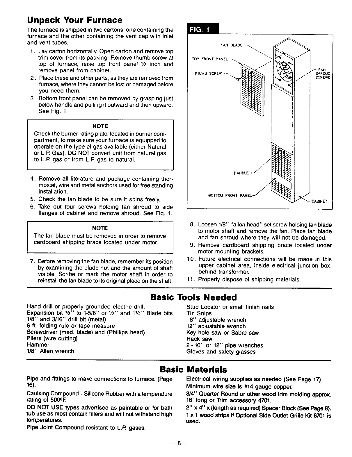
Unpack Your Furnace
The furnace is shipped in two cartons, one containing the
furnace and the other containing the vent cap with inlet
and vent tubes.
1. Lay carton horizontally. Open carton and remove top
trim cover from its packing. Remove thumb screw at
top of furnace, raise top front panel 1/2 inch and
remove panel from cabinet.
2. Place these and other parts, as they are removed from
furnace, where they cannot be lost or damaged before
you need them.
3. Bottom front panel can be removed by grasping just
below handle and pulling it outward and then upward.
See Fig. 1.
NOTE
Check the burner rating plate, located in burner com-
partment, to make sure your furnace is equipped to
operate on the type of gas available (either Natural
or L.P. Gas). DO NOT convert unit from natural gas
to L.P gas or from L.P gas to natural.
I
4. Remove all literature and package containing ther-
mostat, wire and metal anchors used for free standing
installation.
5. Check the fan blade to be sure it spins freely.
6. Take out four screws holding fan shroud to side
flanges of cabinet and remove shroud. See Fig. 1.
NOTE
The fan blade must be removed in order to remove
cardboard shipping brace located under motor.
7. Before removing the fan blade, remember its position
by examining the blade nut and the amount of shaft
visible. Scribe or mark the motor shaft in order to
reinstall the fan blade to its original place on the shaft.
BoTmU FROHT PAHEL-
8. Loosen 1/8" "allen head" set screw holding fan blade
to motor shaft and remove the fan. Place fan blade
and fan shroud where they will not be damaged.
9. Remove cardboard shipping brace located under
motor mounting brackets.
10. Future electrical connections will be made in this
upper cabinet area, inside electrical junction box,
behind transformer.
11. Properly dispose of shipping materials.
Basic Tools Needed
Hand drill or properly grounded electric drill.
Expansion bit 1/2" to 1-5/8" or 1/2" and 11/2'' Blade bits
1/8" and 3/16" drill bit (metal)
6 ft. folding rule or tape measure
Screwdriver (reed. blade) and (Phillips head)
Pliers (wire cutting)
Hammer
1/8" Allen wrench
Stud Locator or small finish nails
Tin Snips
8" adjustable wrench
12" adjustable wrench
Key hole saw or Sabre saw
Hack saw
2 - 10" or 12" pipe wrenches
Gloves and safety glasses
Basic Materials
Pipe and fittings to make connections to furnace. (Page
16).
Caulking Compound -Silicone Rubber with a temperature
rating of 500OF.
DO NOT USE types advertised as paintable or for bath
tub use as most contain fillers and will not withstand high
temperatures.
Electrical wiring supplies as needed (See Page 17).
Minimum wire size is #14 gauge copper.
3/4" Quarter Round or other wood trim molding approx.
16' long or Trim accessory 4701.
2" x 4" x (length as required) Spacer Block (See Page 8).
1 x 1 wood strips if Optional Side Outlet Grille Kit 6701 is
used.
Pipe Joint Compound resistant to L.P. gases.
m5--
Installing Your Wall Furnace
The following steps are needed for proper installation and
safe operation of your furnace. If you have any doubts as
to any requirements, check with local authorities for local
and state codes affecting the installation
Obtain professional help where needed.
DO NOT install these furnaces in a travel trailer, recrea-
tional vehicle or mobile home.
IMPORTANT
For satisfactory and trouble-free operation, be sure to:
1. Properly locate the furnace within the space to be
heated.
2. Provide for adequate combustion air around vent cap
on outside, see Fig. 2 and adequate air circulation
around cabinet inside the open room.
3. Maintain minimum clearance: Floor 0" or ceiling 4",
side wall 4". For exception to minimum side wall
clearance, see Figs. 4, 5 & 6, pg. 7.
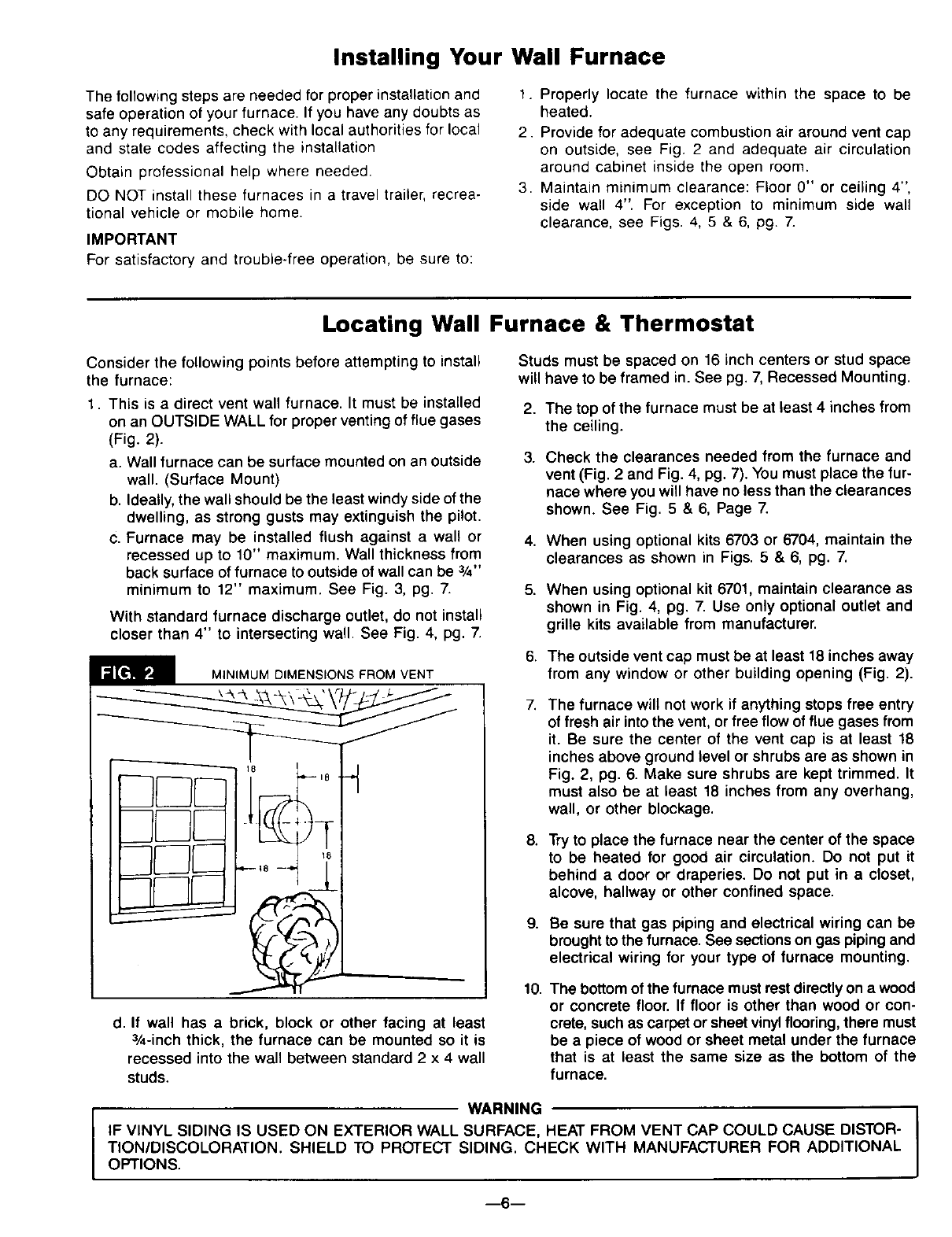
Locating Wall Furnace & Thermostat
Consider the following points before attempting to install
the furnace:
1. This is a direct vent wall furnace. It must be installed
on an OUTSIDE WALL for proper venting of flue gases
(Fig. 2).
a. Wall furnace can be surface mounted on an outside
wall. (Surface Mount)
b. Ideally, the wall should be the least windy side of the
dwelling, as strong gusts may extinguish the pilot.
c. Furnace may be installed flush against a wall or
recessed up to 10" maximum. Wall thickness from
back surface of furnace to outside of wall can be 3/4"
minimum to 12" maximum. See Fig. 3, pg. 7.
With standard furnace discharge outlet, do not install
closer than 4" to intersecting wall. See Fig. 4, pg. 7.
MINIMUM DIMENSIONS FROM VENT
d. If wall has a brick, block or other facing at least
3/4-inch thick, the furnace can be mounted so it is
recessed into the waft between standard 2 x 4 wall
studs.
Studs must be spaced on 16 inch centers or stud space
will have to be framed in. See pg. 7, Recessed Mounting.
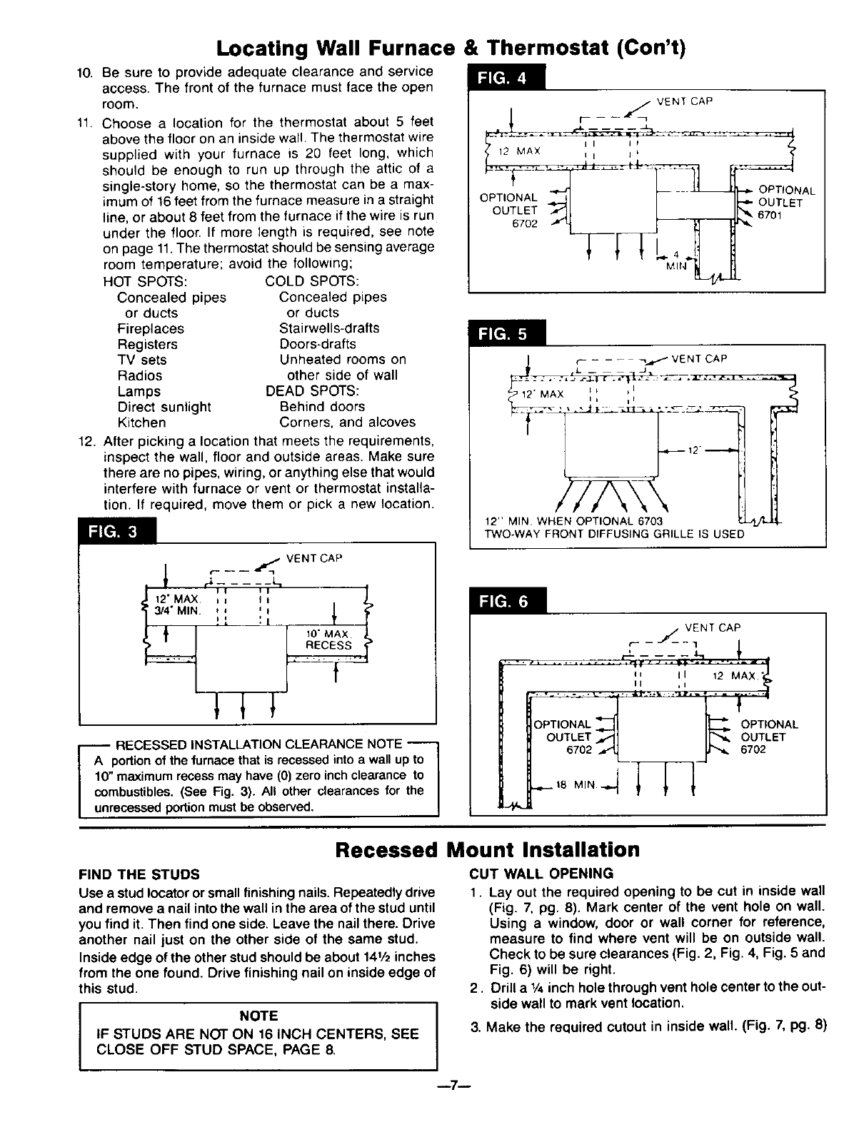
2. The top of the furnace must be at least 4 inches from
the ceiling.
3. Check the clearances needed from the furnace and
vent (Fig. 2 and Fig. 4, pg. 7). You must place the fur-
nace where you will have no less than the clearances
shown. See Fig. 5 & 6, Page 7.
4. When using optional kits 6703 or 6704, maintain the
clearances as shown in Figs. 5 & 6, pg. 7.
5. When using optional kit 6701, maintain clearance as
shown in Fig. 4, pg. 7. Use only optional outlet and
grille kits available from manufacturer.
6. The outside vent cap must be at least 18 inches away
from any window or other building opening (Fig. 2).
7. The furnace will not work if anything stops free entry
of fresh air into the vent, or free flow of flue gases from
it. Be sure the center of the vent cap is at least 18
inches above ground level or shrubs are as shown in
Fig. 2, pg. 6. Make sure shrubs are kept trimmed. It
must also be at least 18 inches from any overhang,
wall, or other blockage.
8. Try to place the furnace near the center of the space
to be heated for good air circulation. Do not put it
behind a door or draperies. Do not put in a closet,
alcove, hallway or other confined space.
9. Be sure that gas piping and electrical wiring can be
brought to the furnace. See sections on gas piping and
electrical wiring for your type of furnace mounting.
10. The bottom of the furnace must rest directly on awood
or concrete floor. If floor is other than wood or con-
crete, such as carpet or sheet vinylflooring, there must
be a piece of wood or sheet metal under the furnace
that is at least the same size as the bottom of the
furnace.
WARNING
IF VINYL SIDING IS USED ON EXTERIOR WALL SURFACE, HEAT FROM VENT CAP COULD CAUSE DISTOR-
TION/DISCOLORATION. SHIELD TO PROTECT SIDING. CHECK WITH MANUFACTURER FOR ADDITIONAL
OPTIONS.
m6--
Locating Wall Furnace & Thermostat (ton't)
10. Be sure to provide adequate clearance and service
access. The front of the furnace must face the open
room.
11. Choose a location for the thermostat about 5 feet
above the floor on an inside wall. The thermostat wire
supplied with your furnace is 20 feet long, which
should be enough to run up through the attic of a
single-story home, so the thermostat can be a max-
imum of 16 feet from the furnace measure in a straight
line, or about 8 feet from the furnace if the wire is run
under the floon If more length is required, see note
on page 11.The thermostat should be sensing average
room temperature; avoid the following;
HOT SPOTS:
Concealed pipes
or ducts
Fireplaces
Registers
TV sets
Radios
Lamps
Direct sunlight
Kitchen
COLD SPOTS:
Concealed pipes
or ducts
Stairwells-drafts
Doors-drafts
Unheated rooms on
other side of wall
DEAD SPOTS:
Behind doors
Corners, and alcoves
12. After picking a location that meets the requirements,
inspect the wall, floor and outside areas. Make sure
there are no pipes, wiring, or anything else that would
interfere with furnace or vent or thermostat installa-
tion. If required, move them or pick a new location.
r-- -- -- _ VENT CAP
12 M Ii _b
_i /I[_" OUTLET
°U:L oT 6,Ol--
¢_.-,,_ VENT CAP
12 MAX I = I
7/%\
12" MIN WHEN OPTIONAL 6703
TWO-WAY FRONT DIFFUSING GRILLE IS USED
t'- -- -- _ VENT CAP
J1 I
'_ 3/4" MIN ',i ':1 I
_10" MAX
[_-A I:x_RECESSEDINSTALLATION CLEARANCE NOTE "-'--1
rflon of the furnace that is recessed into a wall up to {
I 10' maximum recess may have (0) zero inch clearance to I
Icombustibles. (See Fig. 3). All other clearances for the I
[ unrecessed portion must be observed. J
6702
_18 MIN -_
_VENT CAP
OPTIONAL
OUTLET
6702
Recessed Mount Installation
FIND THE STUDS
Use a stud Iocatoror small finishing nails. Repeatedly drive
and remove a nail into the wall in the area of the stud until
you find it. Then find one side. Leave the nail there. Drive
another nail just on the other side of the same stud.
Inside edge of the other stud should be about 141/2inches
from the one found. Drive finishing nail on inside edge of
this stud.
INOTE
IF STUDS ARE NOT ON 16 INCH CENTERS, SEE
CLOSE OFF STUD SPACE, PAGE 8.
CUT WALL OPENING
1. Lay out the required opening to be cut in inside wall
(Fig. 7, pg. 8). Mark center of the vent hole on wall.
Using a window, door or wall corner for reference,
measure to find where vent will be on outside wall.
Check to be sure clearances (Fig. 2, Fig. 4, Fig. 5 and
Fig. 6) will be right.
2. Drill a1/4inch hole through vent hole center to the out-
side wall to mark vent location.
3. Make the required cutout in inside wall. (Fig. 7, pg. 8)
--7--
Recessed Mount Installation (Con't)
4. Using the hole drilled through to the outside wall as
the center, cut a 91/4 inch diameter hole for the vent.
It may be better to work from outside, especially when
breaking through brick, stone or tile. (See Fig. 7).
5. In new stud wall construction, install blocks as shown
in Figure 7 and install plaster grounds around inside
of wall opening.
6. The vertical height of the opening shown is 3 inches
greater than height of furnace to allow space for
connection of wiring after furnace is installed.
NOTE
VERTICAL MEASUREMENTS ARE FROM
FINISHED FLOOR. (Fig. 7)
i,
ELECTRICAL
CONDUIT
91/4, DIA HOLE
THROUGH EXTERIOR
WALL \
68vz°(1)
59"(2i
90 (1)
80_.4,"(2)
BLOCKS
1"x3"
FLOOR
r, .... _ q
WALL OPENING FOR RECESSED INSTALLATION
(1) MODELS
5507332. 5507331, 6257732, AND 6257731
(2) MODELS
4007332, 4007331, 4007732. AND 4007731
CLOSE OFF STUD SPACE (If Required)
If studs are not on 16 inch centers, cut the hole for the
furnace next to an existingstudand frame in the other side
using a2 x 4 and spacer blocks as required. Fig. 8.
If the distance from the top of the cutout to the ceiling wall
plate is more than 18 inches, it is recommended that it be
closed off.
Nail a 2 x 4 long enough to go between the studs at the
top of the opening to close off the stud space.
CEJUNC --F}
PLATE 1
I/
2×'_ BAC_KING J_l
IF _O_E ]HAN /
18" Bg-_t_EH
TOP OF CUTOUT
AND C_3UNG PLJ_TE
I
I
9-1/4" DIA.
HOLE CUTOUT I
EC_qS]]NG STUD _
I
I
1
FLOOR pLATE
ELECTRIC CONNECTION IN TOP
--I --GASINLE''NOOTTO
(1) MODELS
VENT & AIR
BACK
-3V2"
GAS
INLET
SIDE
J__
2"
_.-_ 141/a"
5507332, 5507331, 6257732, AND 6257731
(2) MODELS
4007332, 4(307331, 4007732, AND 4007731
--_787" (1)
7z/e" (2)
;81/2" (1)
s9"(2)
1
_-- FINISH
FLOOR
--8--
Recessed Mount Installation (Con't)
GAS AND ELECTRICAL SUPPLY OPENINGS
Holes must be drilled for the gas line and electrical sup-
ply. Holes must be located from each side of furnace as
shown in Fig. 9, pg, 8.
Decide whether the gas line will come through the floor
or wall.
Drill a 11/2-inch hole in wall or floor as needed.
Gas lines can be run at this time or done after furnace
is mounted, see section: Gas Supply and Piping, pg. 15.
The electrical supply opening should be at the upper left
of the furnace, to match openings shown in Fig. 9, pg. 8.
Mark ceiling wail plate and drill holes. If not practical to
run wiring from the attic, drill holes through wall stud and
run wires up through adjoining stud space from crawl
space or basement.
Run the electrical supply with ground wire and thermostat
cable to the openings. Leave enough length to connect
in the junction box after the furnace is installed. See
section "Electrical Wiring," page 17.
CAUTION
Do not run wire in any location where it might be
damaged. Avoid splicing thermostat wire unless
the spliced wires are properly cleaned, soldered,
and taped.
Offset Wall Installation
To mount the wall furnace on an offset wall, the area
behind the furnace must be made flush or flat.
Use lumber (2 x 4's, 2 x 6's etc.) to furr the offset area to
make the surface flush with other portion of wall.
Use sheet rock or paneling etc. to finish area.
Follow procedures under Surface Mount Installation.
Surface Mount Installation
FIND THE STUDS
1. Find two studs at spot where furnace is to be placed.
Use a stud Iocator or small finishing nails. Repeatedly
drive and remove a nail into the wall in the area of the
stud until you find it. Then find one side. Leave the nail
there. Drive another nail just on the other side of the
same stud.
2. Inside edge of the other stud should be about 141/2
inches from the one found, Drive finishing nail on in-
side edge of this stud.
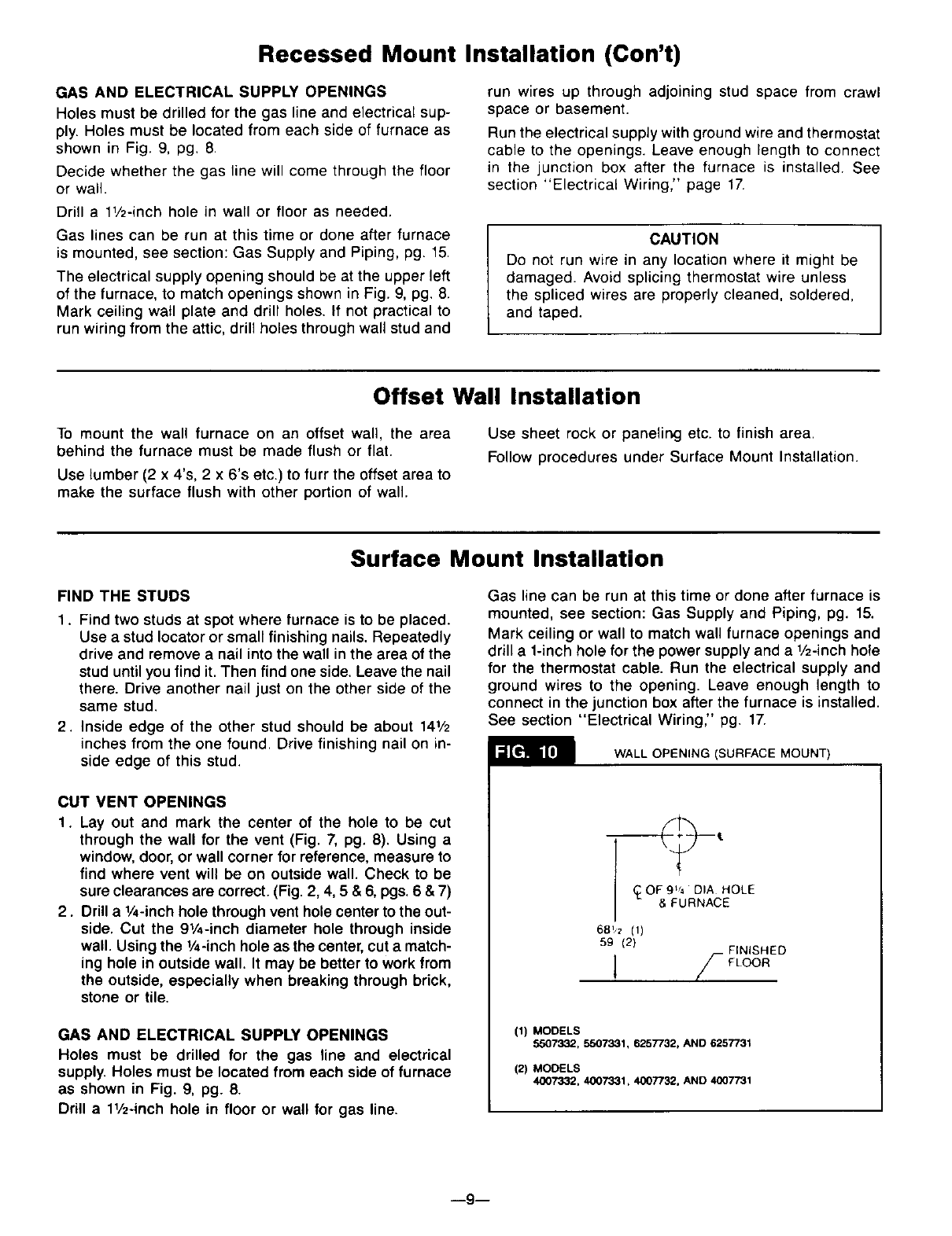
CUT VENT OPENINGS
1. Lay out and mark the center of the hole to be cut
through the wall for the vent (Fig. 7, pg. 8). Using a
window, door, or wall corner for reference, measure to
find where vent will be on outside wall. Check to be
sure clearances are correct. (Fig. 2, 4, 5 & 6, pgs. 6 & 7)
2. Drill a 1/,-inch hole through vent hole center to the out-
side. Cut the 91/,-inch diameter hole through inside
wall. Using the 1/4-inch hole as the center, cut a match-
ing hole in outside wall. It may be better to work from
the outside, especially when breaking through brick,
stone or tile.
GAS AND ELECTRICAL SUPPLY OPENINGS
Holes must be drilled for the gas line and electrical
supply. Holes must be located from each side of furnace
as shown in Fig. 9, pg. 8.
Drill a 11/2-inchhole in floor or wall for gas line.
Gas line can be run at this time or done after furnace is
mounted, see section: Gas Supply and Piping, pg. 15.
Mark ceiling or wall to match wall furnace openings and
drill a 1-inch hole for the power supply and a 1/2-inch hole
for the thermostat cable. Run the electrical supply and
ground wires to the opening. Leave enough length to
connect in the junction box after the furnace is installed.
See section "Electrical Wiring," pg. 17.
WALL OPENING (SURFACE MOUNT)
_OF9t/_ DIA HOLE
& FURNACE
68_ (1)
59 (2)
1/_
(1) MODELS
5507332, 5507331, 6257732, AND 6257731
(2) MODELS
4007332. 4007331, 4007732, AND 4(X)7731
--9--
Surface Mount Installation (Con't)
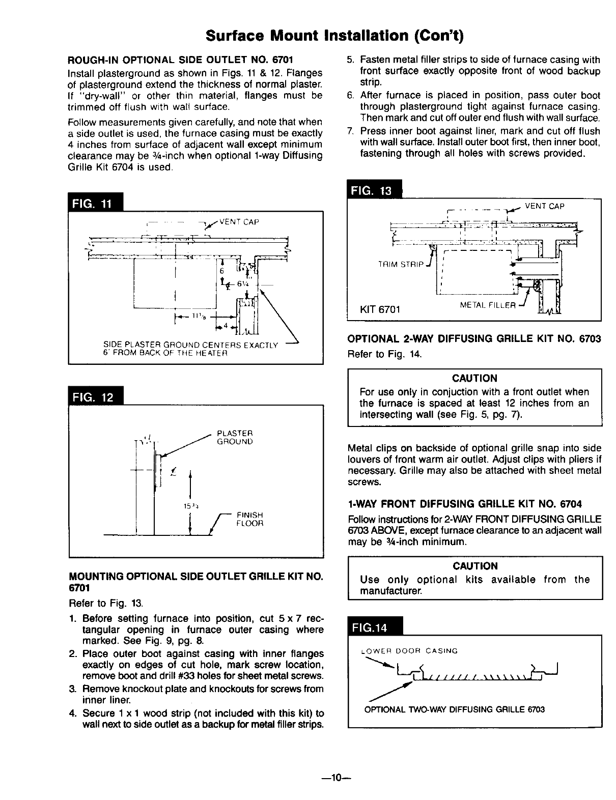
ROUGH-IN OPTIONAL SIDE OUTLET NO. 6701
Install plasterground as shown in Figs. 11 & 12. Flanges
of plasterground extend the thickness of normal piaster.
If "dry-wall" or other thin material, flanges must be
trimmed off flush with wall surface.
Follow measurements given carefully, and note that when
a side outlet is used, the furnace casing must be exactly
4 inches from surface of adjacent wall except minimum
clearance may be 3/4-inch when optional 1-way Diffusing
Grille Kit 6704 is used.
5. Fasten metal filler strips to side of furnace casing with
front surface exactly opposite front of wood backup
strip.
6. After furnace is placed in position, pass outer boot
through plasterground tight against furnace casing.
Then mark and cut off outer end flush with wall surface.
Press inner boot against liner, mark and cut off flush
with wall surface. Installouter boot first, then inner boot,
fastening through all holes with screws provided.
_.-1H 8
SIDE PLASTER GROUND CENTERS EXACTLY
6 FROM RACK OF THE HEATER
i_e]ll ilP,;i
,It" PLASTER
•,, _ GROUND
15]_
FINISH
FLOOR
MOUNTING OPTIONAL SIDE OUTLET GRILLE KIT NO.
6701
Refer to Fig. 13.
1. Before setting furnace into position, cut 5 x 7rec-
tangular opening in furnace outer casing where
marked. See Fig. 9, pg. 8.
2. Place outer boot against casing with inner flanges
exactly on edges of cut hole, mark screw location,
remove boot and drill #33 holes for sheet metal screws.
3. Remove knockout plate and knockoutsfor screws from
inner liner.
4. Secure 1 x 1 wood strip (not included with this kit) to
wall next to side outlet as a backup for metal filler strips.
VENT CAP
F ......
R' STR''I,!,
KIT 6701 METAL FILLER .-J
OPTIONAL 2-WAY DIFFUSING GRILLE KIT NO. 6703
Refer to Fig. 14.
CAUTION
For use only in conjuction with a front outlet when
the furnace is spaced at least 12 inches from an
intersecting wall (see Fig. 5, pg. 7).
Metal clips on backside of optional grille snap into side
louvers of front warm air outlet. Adjust clips with pliers if
necessary. Grille may also be attached with sheet metal
screws.
1-WAY FRONT DIFFUSING GRILLE KIT NO. 6704
Followinstructions for 2-WAYFRONT DIFFUSING GRILLE
6703 ABOVE, except furnace clearance to an adjacent wall
may be 3/4-inch minimum.
CAUTION
Use only optional kits available from the
manufacturer.
LOWER DOOR CASING
OPTIONAL TWO-WAY DIFFUSING GRILLE 6703
--10--
Thermostat Installation
1. If an old thermostat is being replaced and is in a
satisfactory location and the wiring appears to be
in good condition, use existing wiring. If in doubt, use
new wire.
2. If a new location is chosen or if this is a new installa-
tion, thermostat cable must first be run to the location
selected. All wiring must agree with local codes and
ordinances. These instructions cover bringing the wire
down from the attic but it can be run from a basement
or crawl space using similar methods.
3. Before drilling hole in wall at selected location, drive
a small finishing nail through the ceiling in the corner
of the wall and ceiling above the thermostat location.
Pull the nail out and push a small stiff wire through the
hole so it can be found in the attic. Drill a 1/2-inchhole
through the ceiling wall plate.
4. Probe for obstructions in the partition. Then drill a
1/2-inch hole through wall at selected location for
thermostat.
5. From the attic, feed the thermostat cable or a stiff wire
through wall until even with thermostat location.
6. Snag thermostat cable through hole and pull cable
through hole in wall so that 6 inches of cable protrudes.
7. Route cable to wall furnace.
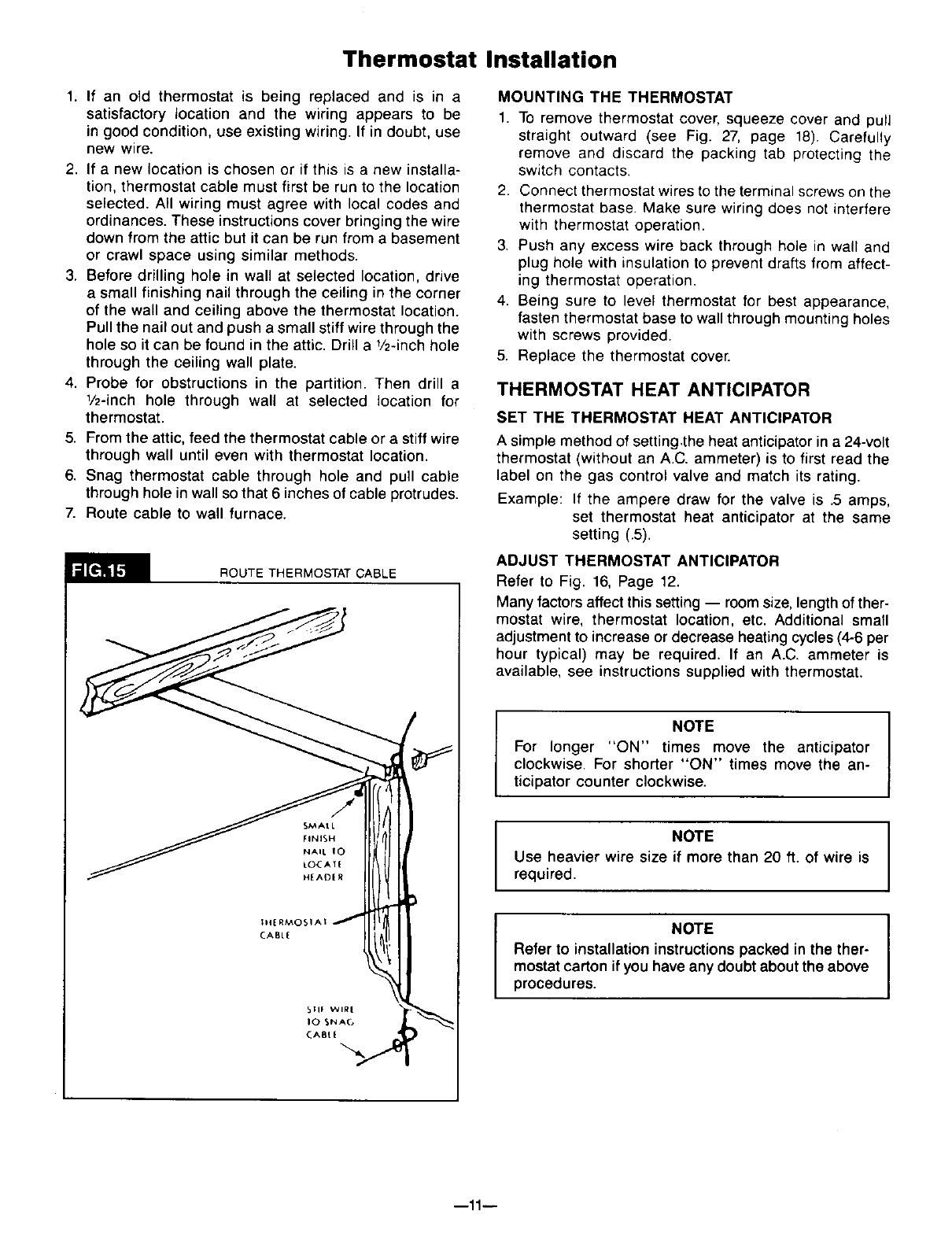
ROUTE THERMOSTAT CABLE
SMAtL
FINISH
NAIL 10
tOCAT{
H[AD[_
MOUNTING THE THERMOSTAT
1. To remove thermostat cover, squeeze cover and pull
straight outward (see Fig. 27, page 18). Carefully
remove and discard the packing tab protecting the
switch contacts.
2. Connect thermostat wires to the terminal screws on the
thermostat base. Make sure wiring does not interfere
with thermostat operation.
3. Push any excess wire back through hole in wall and
plug hole with insulation to prevent drafts from affect-
ing thermostat operation.
4. Being sure to level thermostat for best appearance,
fasten thermostat base to wall through mounting holes
with screws provided.
5. Replace the thermostat cover.
THERMOSTAT HEAT ANTICIPATOR
SET THE THERMOSTAT HEAT ANTICIPATOR
A simple method of setting.the heat anticipator in a 24-volt
thermostat (without an A.C. ammeter) is to first read the
label on the gas control valve and match its rating.
Example: If the ampere draw for the valve is .5 amps,
set thermostat heat anticipator at the same
setting (.5).
ADJUST THERMOSTAT ANTICIPATOR
Refer to Fig. 16, Page 12.
Many factors affect this setting -- room size, lengthof ther-
mostat wire, thermostat location, etc. Additional small
adjustment to increase or decrease heatingcycles (4-6 per
hour typical) may be required. If an A.C. ammeter is
available, see instructions supplied with thermostat.
NOTE
For longer "ON" times move the anticipator
clockwise. For shorter "ON" times move the an-
ticipator counter clockwise.
NOTE
Use heavier wire size if more than 20 ft. of wire is
required.
NOTE
Refer to installation instructions packed in the ther-
mostat carton if you have any doubt about the above
procedures.
I
I
--11--

Thermostat Installation (Con't)
When all is adjusted properly, the furnace burner should
shut off slightly before the desired room temperature is
reached. The stored heat in the appliance is enough to
bring room temperature up to desired level. The heat
anticipator thus makes it possible to maintain very close
temperature control.
Vent Installation
WARNING
DANGER OF PROPERY DAMAGE,
BODILY INJURY OR DEATH.
PROPER VENT INSTALLATION IS CRITICAL TO
THE SAFE OPERATION OF THE FURNACE.
THEREFORE, CAREFULLY READ AND FOLLOW
ALL THE INSTRUCTIONS GIVEN IN THIS
SECTION.
The following instructions are for either surface or recess
mounted wall furnace.
USE ONLY THE VENT ASSEMBLY SUPPLIED.
IMPORTANT
ALL JOINTS IN THE INLET AND VENT TUBES AND
ALL GASKETS MUST BE TIGHT.
INSTALLATION IN ANY OTHER MANNER VOIDS
THE A.G.A. DESIGN CERTIFICATION AND WILL
AFFECT THE WARRANTY.
Refer to Fig. 18, pg. 13 for the name and location of the
vent parts.
DETERMINE PROPER LENGTHS
f
IMPORTANT
To prevent harmful flue gases from entering the
house, make sure NOT to trim air or vent tubes
shorter than specified below.
Air inlet air tube W and vent tube 'B' are supplied in
lengths to handle wall thickness up to 12 inches.
To find the correct vent and air tube length, measure
exact distance 'X' between surface on which back of
cabinet will rest (inside of recessed cavity or face of wall
when freestanding) and the outside wall surface. See Figs.
17 & 18- pg. 13.
Inlet air tube W -- Add 7/8 inch to dimension 'X'. Mark
on tube starting from end with collar and holes. Cut off
evenly. File off any burrs resulting.
Vent tube 'B' -- Add 2-118inches to dimension 'X'. Mark
on tube starting from end with collar and holes. Cut off
evenly. File off any burrs resulting.
CUT ONLY THE PLAIN END (WITHOUT FLANGE)
OF THE TUBES. MAKE A SQUARE CUT TO EXACT
LENGTH.
IU,
\\,l
X
WALL THICKNESS
.--,,--.--d
",----'----I
SURFA(_
MOUNI
U,i
LJ
i\ /
-X
WALL
WIIH
SIOtNG
/
HELPFUL CUTTING HINT
To make a straight cut, measure from the end and mark
tube in several places. Align a piece of tape with the marks
and wrap around the tube. Use the edge of the tape as
a guide to help keep the cut straight.
ATTACHING TUBE TO FURNACE
The smaller diameter vent tube (Fig. 18--"B", pg. 13)must
be installed first.
The easiest way to install the vent tubes and get the
gaskets positioned properly is to have the furnace lying
front down on a flat surface.
IMPORTANT
Be sure not to use longer screws than specified, as
this could keep the furnace from functioning properly. I
1. Attach vent tube (Fig. 18--"B", pg. 13) and gasket to
the back of the furnace heat exchanger with (8) #8 x 3/8
inch sheet metal screws provided.
2. Attach air tube (Fig. 18--"A", pg. 13)and gasket to the
back of the furnace casting with (8) #8 x 3/8 inch sheet
metal screws provided.
--12--
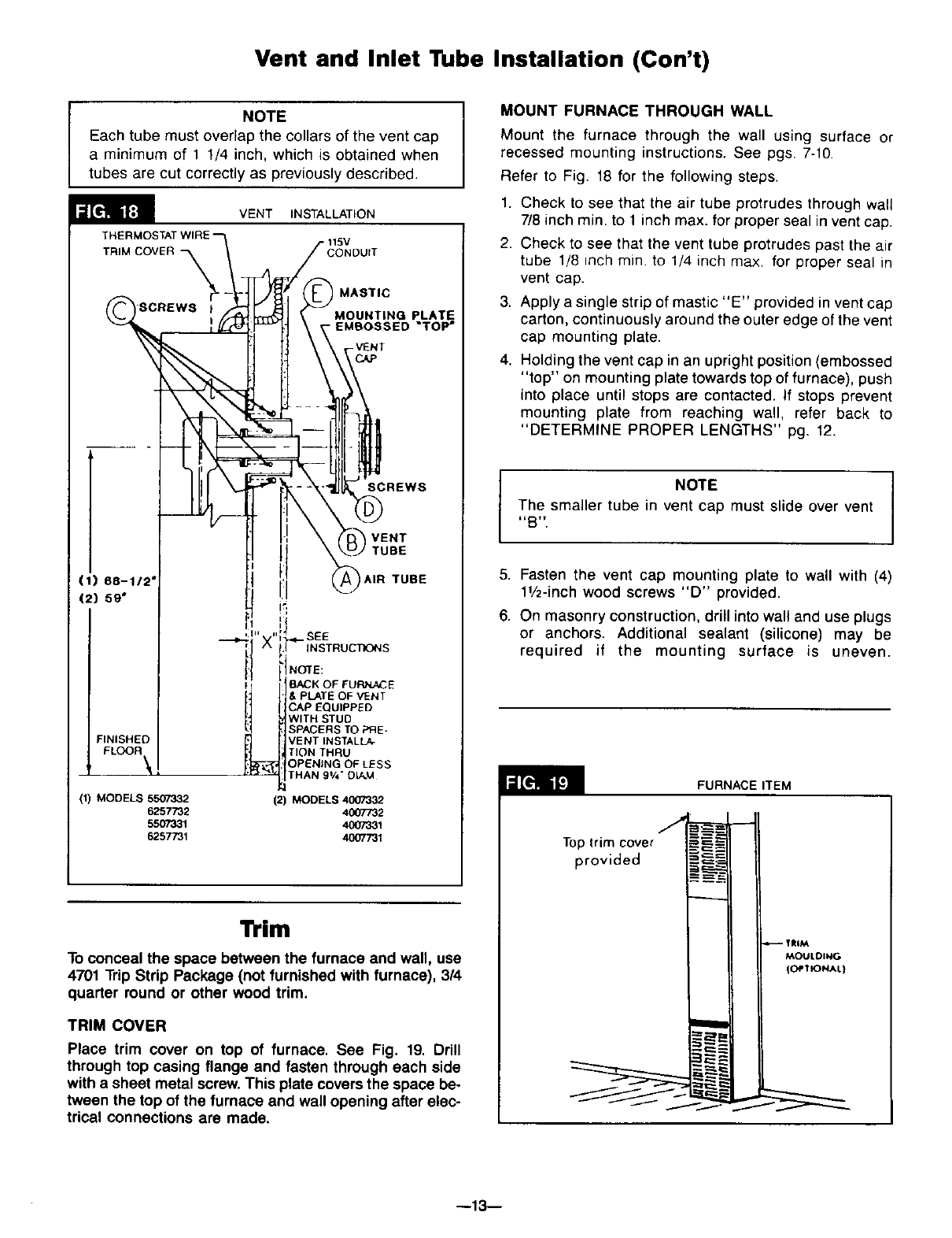
Vent and Inlet Tube Installation (Con't)
NOTE
Each tube must overlap the collars of the vent cap
a minimum of 1 1/4 inch, which is obtained when
tubes are cut correctly as previously described.
VENT INSTALLATION
CONDUIT
(1) 68-112'
(2) 59"
FINISHED
FLOOR \
(1) MODELS 5507332
6257732
55O7331
6257731
MASTIC
MOUNTING PLATE
EMSOSSED "TOP"
SCREWS
VENT
,TUBE
I:1 I,,. TUBE
SEE
INSTRUCTIONS
NOTE:
BACK OF FURNACE
_, PLATE OF VENT
3AP EQUIPPED
WITH STUD
SPACERS TO PRE-
VENT INSTALLA-
TION THRU
OPENING OF LESS
THAN 91/4"DL_.M
(2) MODELS 4007332
4007732
4007331
4007731
Trim
To conceal the space between the furnace and wall, use
4701 Trip Strip Package (not furnished with furnace), 3/4
quarter round or other wood trim.
TRIM COVER
Place trim cover on top of furnace. See Fig. 19. Drill
through top casing flange and fasten through each side
with a sheet metal screw. This plate covers the space be-
tween the top of the furnace and wall opening after elec-
trical connections are made.
MOUNT FURNACE THROUGH WALL
Mount the furnace through the wall using surface or
recessed mounting instructions. See pgs. 7-10.
Refer to Fig. 18 for the following steps.
1. Check to see that the air tube protrudes through wall
7/8 inch min. to 1 inch max. for proper seal in vent cap.
2. Check to see that the vent tube protrudes past the air
tube 1/8 inch rain. to 1/4 inch max. for proper seal in
vent cap.
3. Apply a single strip of mastic "E" provided in vent cap
carton, continuously around the outer edge of the vent
cap mounting plate.
4. Holding the vent cap in an upright position (embossed
"top" on mounting plate towards top of furnace), push
into place until stops are contacted. If stops prevent
mounting plate from reaching wall, refer back to
"DETERMINE PROPER LENGTHS" pg. 12.
NOTE
The smaller tube in vent cap must slide over vent
_B _.
5. Fasten the vent cap mounting plate to wall with (4)
11/2-inch wood screws "D" provided.
6. On masonry construction, drill into wall and use plugs
or anchors. Additional sealant (silicone) may be
required if the mounting surface is uneven.
FURNACEITEM
J
Top trim cover
provided
.c::_
TRiM
MOULDING
(OPTIONAL}
--13--
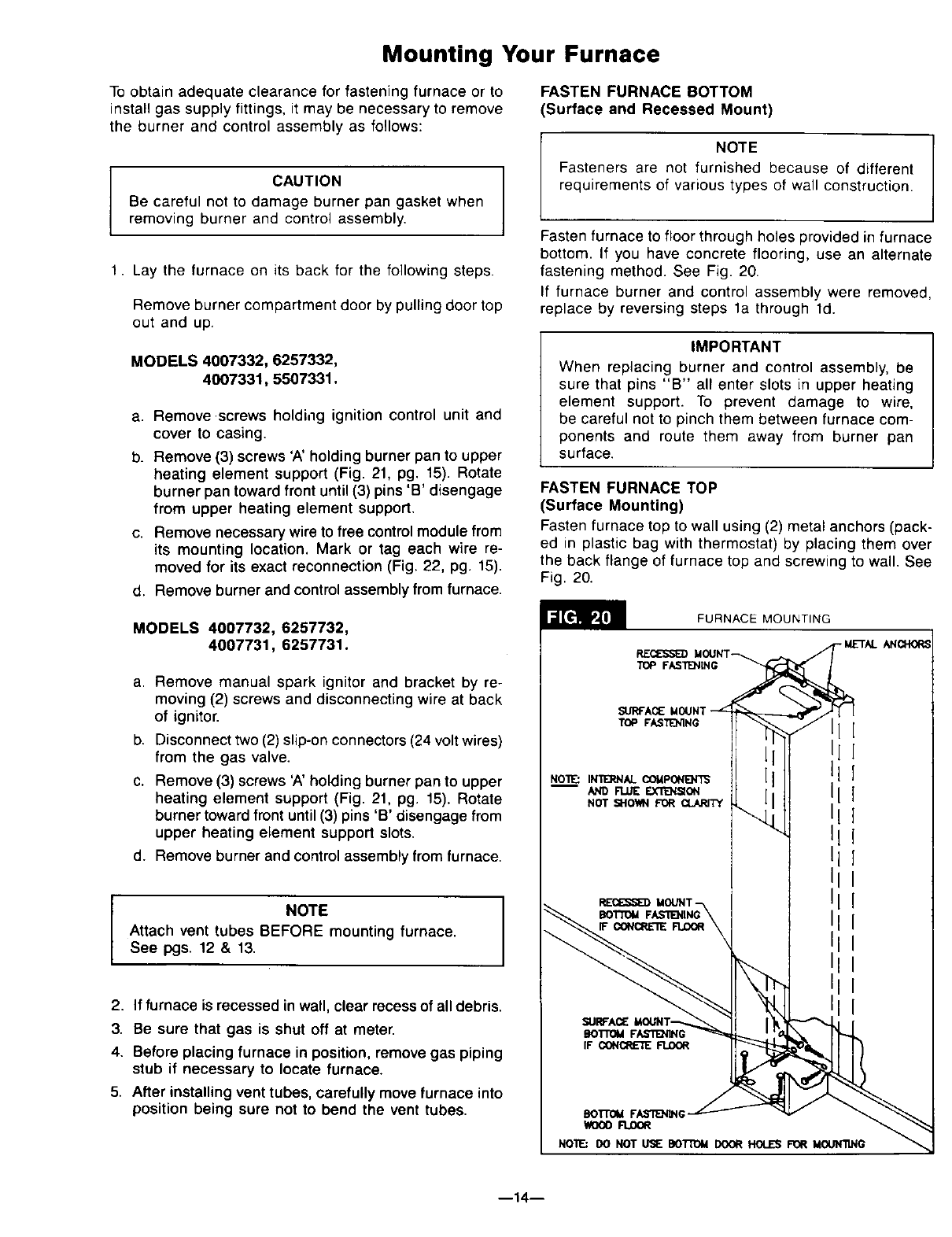
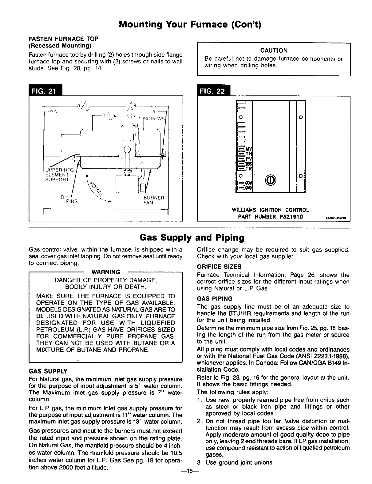
Mounting Your Furnace
To obtain adequate clearance for fastening furnace or to
install gas supply fittings, it may be necessary to remove
the burner and control assembly as follows:
CAUTION
Be careful not to damage burner pan gasket when
removing burner and control assembly.
1. Lay the furnace on its back for the following steps.
Remove burner compartment door by pulling door top
out and up.
MODELS 4007332, 6257332,
4007331, 5507331.
a. Remove screws holdhlg ignition control unit and
cover to casing.
b. Remove (3) screws 'A' holding burner pan to upper
heating element support (Fig. 21, pg. 15). Rotate
burner pan toward front until (3) pins 'B' disengage
from upper heating element support.
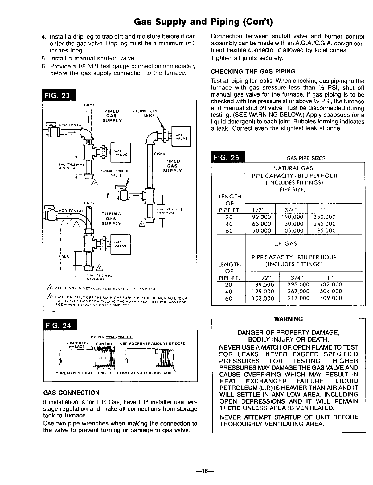
c. Remove necessary wire to free control module from
its mounting location. Mark or tag each wire re-
moved for its exact reconnection (Fig. 22, pg. 15).
d. Remove burner and control assembly from furnace.
FASTEN FURNACE BOTTOM
(Surface and Recessed Mount)
NOTE
Fasteners are not furnished because of different
requirements of various types of wall construction.
Fasten furnace to floor through holes provided in furnace
bottom. If you have concrete flooring, use an alternate
fastening method. See Fig. 20.
If furnace burner and control assembly were removed,
replace by reversing steps la through ld.
IMPORTANT
When replacing burner and control assembly, be
sure that pins "B" all enter slots in upper heating
element support. To prevent damage to wire,
be careful not to pinch them between furnace com-
ponents and route them away from burner pan
surface.
FASTEN FURNACE TOP
(Surface Mounting)
Fasten furnace top to wall using (2) metal anchors (pack-
ed in plastic bag with thermostat) by placing them over
the back flange of furnace top and screwing to wall. See
Fig. 20.
MODELS 4007732, 6257732,
4007731, 6257731.
a. Remove manual spark ignitor and bracket by re-
moving (2) screws and disconnecting wire at back
of ignitor.
b. Disconnect two (2) slip-on connectors (24 voltwires)
from the gas valve.
c. Remove (3) screws 'A' holding burner pan to upper
heating element support (Fig. 21, pg. 15). Rotate
burner toward front until (3) pins 'B' disengage from
upper heating element support slots.
d. Remove burner and control assembly from furnace.
NOTE
Attach vent tubes BEFORE mounting furnace.
See pgs. 12 & 13.
2. If furnace is recessed in wall, clear recess of all debris.
3. Be sure that gas is shut off at meter.
4. Before placing furnace in position, remove gas piping
stub if necessary to locate furnace.
5. After installing vent tubes, carefully move furnace into
position being sure not to bend the vent tubes.
FURNACE MOUNTING
RECESSEDMOUNT
_REA_ MOUNT
TOP FASTENING
NOT _-I0_1 FOR
II
II
BOI"rOMFAS'T1E]_NG
WDOOFLDOR
NO'W.: DO NOT USE DOTrOM DOOR HOLES FOR MOLJNllNG
--14--
Mounting Your Furnace (ton't)
FASTEN FURNACE TOP
(Recessed Mounting)
Fasten furnace top by drilling (2) holes through side flange
furnace top and securing with (2) screws or nails to wall
studs. See Fig. 20, pg. 14. CAUTION I
Be careful not to damage furnace components or
wiring when drilling holes.
5 ,
L
oIo
Io
WlLUAMS IGNITION CONTROL
PART NUMBER P3219t0
Gas Supply and Piping
Gas control valve, within the furnace, is shipped with a
seal cover gas inlet tapping. Do not remove seal until ready
to connect piping.
WARNING
DANGER OF PROPERTY DAMAGE,
BODILY INJURY OR DEATH.
MAKE SURE THE FURNACE IS EQUIPPED TO
OPERATE ON THE TYPE OF GAS AVAILABLE.
MODELS DESIGNATED AS NATURAL GAS ARE TO
BE USED WITH NATURAL GAS ONLY. FURNACE
DESIGNATED FOR USE WITH LIQUEFIED
PETROLEUM (L.R) GAS HAVE ORIFICES SIZED
FOR COMMERCIALLY PURE PROPANE GAS.
THEY CAN NOT BE USED WITH BUTANE OR A
MIXTURE OF BUTANE AND PROPANE.
GAS SUPPLY
For Natural gas, the minimum inlet gas supply pressure
for the purpose of input adjustment is 5" water column.
The Maximum inlet gas supply pressure is 7" water
column.
For L.IR gas, the minimum inlet gas supply pressure for
the purpose of input adjustment is 11" water column. The
maximum inlet gas supply pressure is 13" water column.
Gas pressures and input to the burners must not exceed
the rated input and pressure shown on the rating plate.
On Natural Gas, the manifold pressure should be 4 inch-
es water column. The manifold pressure should be 10.5
inches water column for LP. Gas See pg. 18 for opera-
tion above 2000 feet altitude. --15--
Orifice change may be required to suit gas supplied.
Check with your local gas supplier.
ORIFICE SIZES
Furnace Technical Information, Page 26, shows the
correct orifice sizes for the different input ratings when
using Natural or L.R Gas.
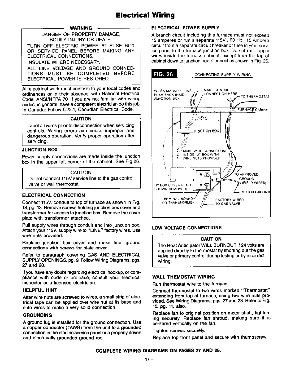
GAS PIPING
The gas supply line must be of an adequate size to
handle the BTU/HR requirements and length of the run
for the unit being installed.
Determine the minimum pipe size from Fig. 25, pg. 16, bas-
ing the length of the run from the gas meter or source
to the unit.
All piping must comply with local codes and ordinances
or with the National Fuel Gas Code (ANSI Z22&l-1988),
whichever applies. In Canada: Follow CAN/CGA B149 In-
stallation Code.
Refer to Fig. 23, pg. 16 for the general layout at the unit.
It shows the basic fittings needed.
The following rules apply:
1. Use new, properly reamed pipe free from chips such
as steel or black iron pipe and fittings or other
approved by local codes.
2. Do not thread pipe too far. Valve distortion or mal-
function may result from excess pipe within control.
Apply moderate amount of good quality dope to pipe
only, leaving 2 end threads bare. If LP gas installation,
use compound resistant to action of liquefied petroleum
gases.
3. Use ground joint unions.
Gas Supply and Piping (Con't)
4. Install a drip leg to trap dirt and moisture before it can
enter the gas valve. Drip leg must be a minimum of 3
inches long.
5. Install a manual shut-off valve.
6. Provide a 1/8 NPT test gauge connection immediately
before the gas supply connection to the furnace.
DROp
IPIpIE D GROUNO JOINT
3, [ 62mml GAS
_tt_rMUM _ANUAL SHUT OFF SUPPLY
HOnlZON'r AL TUBING _It_IMUM
;oF:
_ 31n 1762mml
M_NIMUM
_ALL BENDS IN METALLIC TUBING SHOULO 9E SMOOTH
_ CAUTION: SHOT OF€ THE MA_N CA$ SUPPLY BE,_ORE REMOVING ENO CAP
TO PREVI_NT GAS FROM F(LLINC THE WORK AAEA TE_T FOR GAS LEAK.
AGE WHEN INSTALLATION I_ COMPLETE
Connection between shutoff valve and burner control
assembly can be made with an A.G.A./C.G.A. design cer-
tified flexible connector if allowed by local codes.
Tighten all joints securely.
CHECKING THE GAS PIPING
Test all piping for leaks. When checking gas piping to the
furnace with gas pressure less than 1/2 PSI, shut off
manual gas valve for the furnace. If gas piping is to be
checked with the pressure at or above 1/2PSI, the furnace
and manual shut off valve must be disconnected during
testing. (SEE WARNING BELOW.) Apply soapsuds (or a
liquid detergent) to each joint. Bubbles forming indicates
a leak. Correct even the slightest leak at once.
GAS PIPE SIZES
NATURAL GAS
PIPE CAPACITY - BTU PER HOUR
(INCLUDES FITTINGS)
PIPE SIZE.
LENGTH
OF
PIPE-FT. I/2" 3/4" I"
20 92,000 190.000 350,000
40 63.000 130,000 245.000
60 S0,000 105,000 195,000
L.P, GAS
PIPE CAPACITY - BTU PER HOUR
LENGTH (INCLUDES FITTINGS)
OF
PIPE-FT. 1/2" 3/4" 1"
20 189,000 393,000 732,000
40 129.000 267,000 504,000
60 103,000 217.000 409,000
WARNING
PROP[R PtPtMG PRACTI¢_
2 IMPERFECT CONTRO L USE MODERATE AMOUNT OF DOPE
THR£AD5
\
THREAD PIPE RIGHT L_NGTH LEAVE 2 END THREADS 8ARE "_
GAS CONNECTION
If installation isfor L.R Gas, have L.R installer use two-
stage regulation and make all connections from storage
tank to furnace.
Use two pipe wrenches when making the connection to
the valve to prevent turning or damage to gas valve.
DANGER OF PROPERTY DAMAGE,
BODILY INJURY OR DEATH.
NEVER USE A MATCH OR OPEN FLAME TO TEST
FOR LEAKS. NEVER EXCEED SPECIFIED
PRESSURES FOR TESTING. HIGHER
PRESSURES MAY DAMAGE THE GAS VALVE AND
CAUSE OVERFIRING WHICH MAY RESULT IN
HEAT EXCHANGER FAILURE. LIQUID
PETROLEUM (L.R) IS HEAVIER THAN AIR AND IT
WILL SETTLE IN ANY LOW AREA, INCLUDING
OPEN DEPRESSIONS AND IT WILL REMAIN
THERE UNLESS AREA IS VENTILATED.
NEVER ATTEMPT STARTUP OF UNIT BEFORE
THOROUGHLY VENTILATING AREA.
--16--
Electrical Wiring
WARNING
DANGER OF PROPERTY DAMAGE,
BODILY INJURY OR DEATH.
TURN OFF ELECTRIC POWER AT FUSE BOX
OR SERVICE PANEL BEFORE MAKING ANY
ELECTRICAL CONNECTIONS.
INSULATE WHERE NECESSARY.
ALL LINE VOLTAGE AND GROUND CONNEC-
TIONS MUST BE COMPLETED BEFORE
ELECTRICAL POWER IS RESTORED.
All electrical work must conform to your local codes and
ordinances or in their absence, with National Electrical
Code, ANSI/NFPA 70. If you are not familiar with wiring
codes, in general, have a competent electrician do this job.
In Canada: Follow C22.1, Canadian Electrical Code.
CAUTION
Label all wires prior to disconnection when servicing
controls. Wiring errors can cause improper and
dangerous operation. Verify proper operation after
servicing.
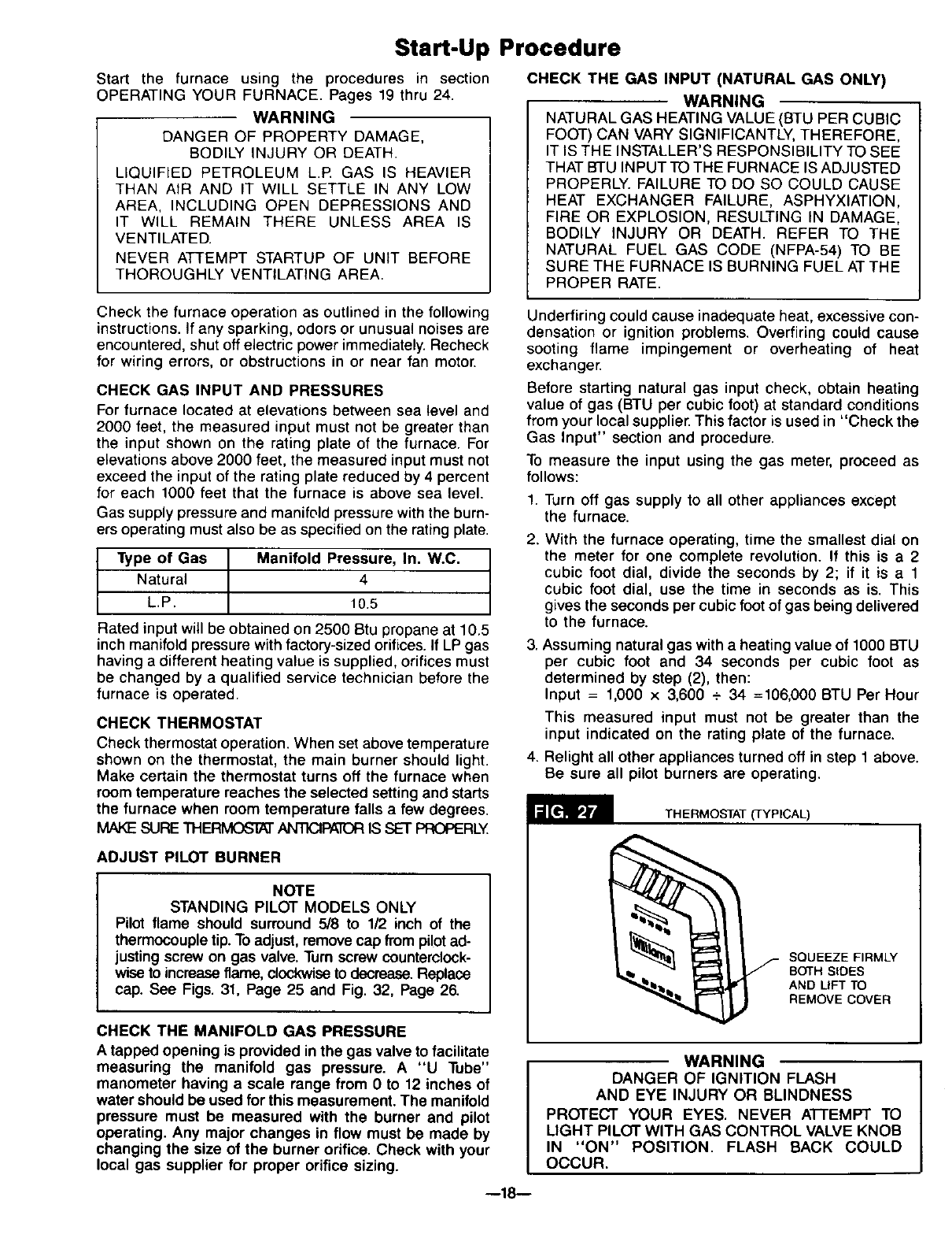
JUNCTION BOX
Power supply connections are made inside the junction
box in the upper left corner of the cabinet. See Fig.26.
CAUTION I
Do not connect 115V service line to the gas control
valve or wall thermostat.
ELECTRICAL CONNECTION
Connect 115V. conduit to top of furnace as shown in Fig.
18, pg. 13. Remove screws holding junction box cover and
transformer for access to junction box. Remove the cover
plate with transformer attached.
Pull supply wires through conduit and into junction box.
Attach your 115V.supply wire to "LINE" factory wires. Use
wire nuts provided.
Replace junction box cover and make final ground
connections with screws for plate cover.
Refer to paragraph covering GAS AND ELECTRICAL
SUPPLY OPENINGS, pg. 9. Follow Wiring Diagrams, pgs.
27 and 28.
If you have any doubt regarding electrical hookup, or com-
pliance with code or ordinace, consult your electrical
inspector or a licensed electrician.
HELPFUL HINT
After wire nuts are screwed to wires, a small strip of elec-
trical tape can be applied over wire nut at its base and
onto wires to make a very solid connection.
GROUNDING
A ground lug is installed for the ground connection. Use
a copper conductor (#AWG) from the unit to a grounded
connection in the electric service panel or a propedy driven
and electrically grounded ground rod.
ELECTRICAL POWER SUPPLY
A branch circuit including this furnace must not exceed
15 amperes or run a separate 115V., 60 Hz., 15 Ampere
circuit from a separate circuit breaker or fuse in your serv-
ice panel to the furnace junction box. Do not run supply
wires inside the furnace cabinet, except from the top of
cabinet down to junction box. Connect as shown in Fig. 26.
CONNECTING SUPPLY WIRING
WIRES MARKED LINE
PUSH BACK INSIDE
JUNC lION BOX
MAKE CONDUIT
CONNECTION HERE
_ ,,__ lO THERMOSTA"
_ !!) AO,NE
MAKE WIRE CONNECTIONS
"J" BOX COVER PLATE
_HOWN REMOVED)
TO APPROVED
GROUND
_(FIELD WIRED)
MOTOR GROUNI
FACTORY WIRED
ON TRANSFORMER TO GAS VALVE
LOW VOLTAGE CONNECTIONS
CAUTION
The Heat Anticipator WILL BURNOUT if 24 volts are
applied directly to thermostat by shorting out the gas
valve or primary control during testing or by incorrect
wiring.
WALL THEMOSTAT WIRING
Run thermostat wire to the furnace.
Connect thermostat to two wires marked "Thermostat"
extending from top of furnace, using two wire nuts pro-
vided. See Wiring Diagrams, pgs. 27 and 28. Refer to Fig.
15, pg. 11, also,
Replace fan to original position on motor shaft, tighten-
ing securely. Replace fan shroud, making sure it is
centered vertically on the fan.
Tighten screws securely.
Replace top front panel and secure with thumbscrew.
COMPLETE WIRING DIAGRAMS ON PAGES 27 AND 28.
--17--
Start-Up Procedure
Start the furnace using the procedures in section
OPERATING YOUR FURNACE. Pages 19 thru 24.
WARNING
DANGER OF PROPERTY DAMAGE,
BODILY INJURY OR DEATH.
LIQUIFIED PETROLEUM L.IR GAS IS HEAVIER
THAN AIR AND IT WILL SETTLE IN ANY LOW
AREA, INCLUDING OPEN DEPRESSIONS AND
IT WILL REMAIN THERE UNLESS AREA IS
VENTILATED.
NEVER ATTEMPT STARTUP OF UNIT BEFORE
THOROUGHLY VENTILATING AREA.
CHECK THE GAS INPUT (NATURAL GAS ONLY)
WARNING
NATURAL GAS HEATING VALUE (BTU PER CUBIC
FOOT) CAN VARY SIGNIFICANTLY, THEREFORE,
IT IS THE INSTALLER'S RESPONSIBILITY TO SEE
THAT BTU INPUT TO THE FURNACE IS ADJUSTED
PROPERLY. FAILURE TO DO SO COULD CAUSE
HEAT EXCHANGER FAILURE, ASPHYXIATION,
FIRE OR EXPLOSION, RESULTING IN DAMAGE,
BODILY INJURY OR DEATH. REFER TO THE
NATURAL FUEL GAS CODE (NFPA-54) TO BE
SURE THE FURNACE IS BURNING FUEL AT THE
PROPER RATE.
Check the furnace operation as outlined in the following
instructions. If any sparking, odors or unusual noises are
encountered, shut off electric power immediately. Recheck
for wiring errors, or obstructions in or near fan motor.
CHECK GAS INPUT AND PRESSURES
For furnace located at elevations between sea level and
2000 feet, the measured input must not be greater than
the input shown on the rating plate of the furnace. For
elevations above 2000 feet, the measured input must not
exceed the input of the rating plate reduced by 4 percent
for each 1000 feet that the furnace is above sea level.
Gas supply pressure and manifold pressure with the burn-
ers operating must also be as specified on the rating plate.
Type of Gas Manifold Pressure, In. W.C. |
Natural 4 ]
L.P. 10.5
Rated input will be obtained on 2500 Btu propane at 10.5
inch manifold pressure with factory-sized orifices. If LP gas
having a different heating value is supplied, orifices must
be changed by a qualified service technician before the
furnace is operated.
CHECK THERMOSTAT
Check thermostat operation. When set above temperature
shown on the thermostat, the main burner should light.
Make certain the thermostat turns off the furnace when
room temperature reaches the selected setting and starts
the furnace when room temperature falls afew degrees.
SURE TH_ ANTICIPATORIS SET PROPERLY
ADJUST PILOT BURNER
NOTE
STANDING PILOT MODELS ONLY
Pilot flame should surround 5/8 to 1/2 inch of the
thermocouple tip. Toadjust, remove cap from pilotad-
justing screw on gas valve. Turn screw counterclock-
wise to increase flame, clockwiseto decrease. Replace
cap. See Figs, 31, Page 25 and Fig. 32, Page 26.
CHECK THE MANIFOLD GAS PRESSURE
A tapped opening is provided in the gas valve to facilitate
measuring the manifold gas pressure. A "U Tube"
manometer having a scale range from 0 to 12 inches of
water should be used for this measurement. The manifold
pressure must be measured with the burner and pilot
operating, Any major changes in flow must be made by
changing the size of the burner orifice, Check with your
local gas supplier for proper orifice sizing.
Underfiring could cause inadequate heat, excessive con-
densation or ignition problems. Overfiring could cause
sooting flame impingement or overheating of heat
exchanger.
Before starting natural gas input check, obtain heating
value of gas (BTU per cubic foot) at standard conditions
from your local supplier. This factor is used in "Check the
Gas Input" section and procedure.
To measure the input using the gas meter, proceed as
follows:
1. Turn off gas supply to all other appliances except
the furnace.
2. With the furnace operating, time the smallest dial on
the meter for one complete revolution. If this is a 2
cubic foot dial, divide the seconds by 2; if it is a 1
cubic foot dial, use the time in seconds as is. This
gives the seconds per cubic foot of gas being delivered
to the furnace.
3. Assuming natural gas with a heating value of 1000 BTU
per cubic foot and 34 seconds per cubic foot as
determined by step (2), then:
Input = 1,000 x 3,600 + 34 =106,000 BTU Per Hour
This measured input must not be greater than the
input indicated on the rating plate of the furnace.
4. Relight all other appliances turned off in step 1 above.
Be sure all pilot burners are operating.
THERMOSTAT (TYPICAL)
SQUEEZE FIRMLY
BOTH SIDES
AND LIFT TO
REMOVE COVER
WARNING
DANGER OF IGNITION FLASH
AND EYE INJURY OR BLINDNESS
PROTECT YOUR EYES. NEVER ATTEMPT TO
LIGHT PILOT WITH GAS CONTROL VALVE KNOB
IN "ON" POSITION. FLASH BACK COULD
OCCUR.
--18--
Operating Your Furnace
STANDING PILOT MODELS"
4007732, 6257732,
4007731, 6257731.
NOTE:
For models equipped with WILLIAMS gas valve P322041
or P322042 refer to this sheet and sheet 20 for "SAFETY
& LIGHTING INSTRUCTION" and "TURN GAS OFF TO
APPLIANCE."
For models equipped with WILLIAMS gas valve P321704
or P321705 refer to this sheet and sheet 21 for "SAFETY
& LIGHTING INSTRUCTIONS" and "TURN GAS OFF TO
APPLIANCE."
(All other models refer to sheet 22, 23 &24.)
These furnaces are equipped with a manually operated
Piezo spark igniter device to ignite the pilot gas. Follow
the steps under "Lighting Instructions" (see Page 20 or
Page 21)and use the manual spark ignitor to light the pilot
in Step 10. Press spark ignitor button repeatedly.
On new installations, the gas lines will be filled with air
and it may take several minutes to establish the pilot flame.
Keep all access doors and panels in place except for in-
spection and maintenance.
WARNING
DANGER OF BODILY INJURY OR DEATH.
DO NOT OPERATE THE FURNACE WITH A
BROKEN OR MISSING PILOT OBSERVATION
DOOR.
For models equipped with WILLIAMS gas valve
P321704 or P321705.
Models are equipped with a two-rate control valve. The rate
knob on the gas valve is marked "LO" and "HI." Turn the
rate knob to the "LO" position and the room thermostat
will operate the main burner at about 70% of maximum
capacity. Turn the rate knob to the "HI" position only when
a fast heat-up is desired during extremely cold weather.
High operation develops maximum capacity of the furnace
A two-speed fan is used with Models 6257732, and
6257731.
Blower will operate at low speed then shift to high speed
as the furnace heats up.
WARNING
THE SURFACE OF THE FURNACE IS HOT DUR-
ING OPERATION. KEEP CHILDREN, CLOTHING,
FRNITURE, AND FLAMMABLE MATERIAL AWAY
FROM IT.
DO NOT STORE OR USE GASOLINE OR OTHER
FLAMMABLE LIQUIDS OR VAPORS NEAR THE
FURNACE.
WARNING
DANGER OF PROPERTY DAMAGE
BODILY INJURY OR DEATH.
IF THE FURNACE OVERHEATS OR FAILS TO
SHUT OFF, CLOSE MANUAL GAS VALVE FOR THE
FURNACE BEFORE TURNING OFF ELECTRIC
POWER.
SAFETY LIMIT CONTROL
These furnaces are protected against unsafe operation by
four automatic safety controls: (1)A safety pilot acts to shut
OFF the gas valve in case of pilot failure; (2) A redundant
gas valve; (3) A limit switch shuts down the main burner
to prevent overheating the furnace cabinet; this limit switch
will reset when furnace cools; and (4) A thermal overload
protects the motor against burnout caused by current
surges or if anything should block the flow of air through
the furnace. This switch will reset itself when the motor
cools down and it cannot be adjusted.
--19--
FOR YOUR SAFETY, READ BEFORE LIGHTING
I WARNING: If you do not follow these instructions exactly, a fire or explosion I
may result causing property damage, personal injury or loss of life. I
A. This appliance has a pilot which must be lighted by
hand, When lighting the pilot, follow these instructions
exactly.
B. BEFORE LIGHTING smell around the appliance area
for gas. Be sure to smell next to the floor because some
gas is heavier than air and will settle on the floor.
WHAT TO DO IF YOU SMELL GAS
•Do not try to light any appliance or strike a match.
•Do not touch any electric switch; do not use any
phone in your building.
•Immediately call your gas supplier from a neighbor's
phone. Follow the gas supplier's instructions.
C.
D.
•If you cannot reach your gas supplier, call the fire
department.
Use only your hand to push in or turn the gas control
knob. Never use tools. If the knob will not push in or
turn by hand, don't try to repair it, call a qualified serv-
ice technician, Force or attempted repair may result in a
fire or explosion,
Do not use this appliance if any part has been under
water. Immediately call a qualified service technician to
inspect the appliance and to replace any part of the
control system and any gas control which has been
under water.
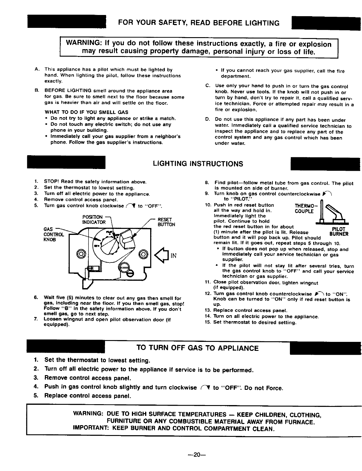
LIGHTING INSTRUCTIONS
1. STOP! Read the safety information above.
2. Set the thermostat to lowest setting.
3. Turn off all electric power to the appliance.
4. Remove control access panel.
5. Turn gas control knob clockwise _to "OFF".
GAS
CONTROL
KNOB
RESET
BUTTON
6. Wait five (5) minutes to clear out any gas then smell for
gas, including near the floor. If you then smell gas, stop!
Follow "B" in the safety information above. If you don't
smell gas, go to next step.
7. Loosen wingnut and open pilot observation door (if
equipped).
8. Find pilot--follow metal tube from gas control, The pilot
is mounted on side of burner.
9. Turn knob on gas control counterclockwise J_
to "PILOT,"
10. Push in red reset button THERMO-_1 ,[_,=
all the way and hold in. COUPLE
Immediately light the
pilot. Continue to hold
the red reset button in for about PILOT
(1) minute after the pilot is lit, Release BURNER
button and it will pop back up. Pilot should
remain lit. If it goes out, repeat steps 5 through 10.
•If button does not pop up when released, stop and
immediately call your service technician or gas
supplier,
•If the pilot will not stay lit after several tries, turn
the gas control knob to "OFF" and call your service
technician or gas supplier.
11. Close pilot observation door, tighten wingnut
(if equipped),
12. Turn gas control knob counterclockwise _to "ON",
Knob can be turned to "ON" only if red reset button is
up.
13. Replace control access panel.
14. Turn on all electric power to the appliance.
15. Set thermostat to desired setting.
TO TURN OFF GAS TO APPLIANCE
1. Set the thermostat to lowest setting.
2. Turn off all electric power to the appliance if service is to be performed.
3. Remove control access panel.
4. Push in gas control knob slightly and turn clockwise _to "OFF". Do not Force.
5. Replace control access panel.
WARNING: DUE TO HIGH SURFACE TEMPERATURES -- KEEP CHILDREN, CLOTHING,
FURNITURE OR ANY COMBUSTIBLE MATERIAL AWAY FROM FURNACE.
IMPORTANT: KEEP BURNER AND CONTROL COMPARTMENT CLEAN.
--20--
FOR YOUR SAFETY, READ BEFORE LIGHTING
WARNING: If you do not follow these instructions exactly, a fire or explosion
may result causing property damage, personal injury or loss of life,
A. This appliance has a pilot which must be lighted by
hand. When lighting the pilot, follow these instructions
exactly.
B. BEFORE LIGHTING smell around the appliance area
for gas. Be sure to smell next to the floor because some
gas is heavier than air and will settle on the floor.
WHAT TO DO IF YOU SMELL GAS
•Do not try to light any appliance or strike a match.
•Oo not touch any electric switch; do not use any
phone in your building.
• immediately call your gas supplier from a neighbor's
phone, Follow the gas supplier'a Instructions.
C.
O.
• If you cannot reach your gas supplier, call the fire
department.
Use only your hand to push in or move the selector
arm. Never use tools. If the arm will not push in or
move by hand, don't try to repair it, call a qualified
service technician. Force or attempted repair may result
in a fire or explosion.
Do not use this appliance if any part has been under
water. Immediately call a qualified service technician to
inspect the appliance and to replace any part of the
control system and any gas control which has been
under water.
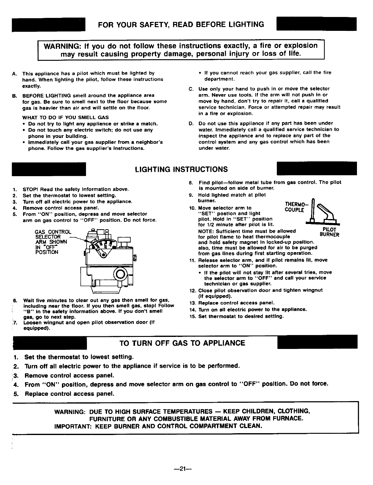
LIGHTING INSTRUCTIONS
1. STOP! Read the safety information above.
2. Set the thermostat to lowest setting,
3. Turn off all electric power to the appliance.
4. Remove control access panel.
5. From "ON" position, depress and move selector
arm on gas control to "OFF" position, Do not force.
GAS CONTROL
SELECTOR
ARM SHOWN
IN =OFF"
POSITION
6. Wait five minutes to clear out any gas then smell for gas,
including near the floor. If you then smell gas, stop! Follow
"B'" In the safety information above. If you don't smell
gas, go to next step.
:7. Loosen wingnut and open pilot observation door (if
equipped).
8.
9.
f0.
Find pilot--follow metal tube from gas control. The pilot
is mounted on side of burner.
Hold lighted match at pilot
burner.
Move selector arm to
"SET" postlon and light
pilot, Hold in "SET" position
for 1/2 minute after pilot is lit.
NOTE: Sufficient time must be allowed PILOT
for pilot flame to heat thermocouple BURNER
and hold safety magnet in locked-up position,
also, time must be allowed for air to be purged
from gas lines during first starting operation.
11. Release selector arm, and if pilot remains lit, move
selector arm to "ON" position,
•If the pilot will not stay lit after several tries, move
the selector arm to "OFF" and call your service
technician or gas supplier.
12. Close pilot observation door and tighten wingnut
(if equipped).
13. Replace control access panel.
14. Turn on all electric power to the appliance.
15. Set thermostat to desired setting.
TO TURN OFF GAS TO APPLIANCE
1. Set the thermostat to lowest setting.
2. Turn off all electric power to the appliance if service is to be performed.
13. Remove control access panel.
4. From "ON" position, depress and move selector arm on gas control to "OFF" position. Do not force.
5. Replace control access panel.
WARNING: DUE TO HIGH SURFACE TEMPERATURES -- KEEP CHILDREN, CLOTHING,
FURNITURE OR ANY COMBUSTIBLE MATERIAL AWAY FROM FURNACE.
IMPORTANT: KEEP BURNER AND CONTROL COMPARTMENT CLEAN.
--21--
Operating Your Furnace
ELECTRONIC IGNITION MODELS*
4007332, 5507332,
4007331, 5507331.
NOTE:
For models equipped with WILLIAMS gas valve P322043
or P322044 refer to this sheet and sheet 23 for "SAFETY
& LIGHTING INSTRUCTION" and "TURN GAS OFF TO
APPLIANCE."
For models equipped with WILLIAMS gas valve P321897
or P321898 refer to this sheet and sheet 24 for "SAFETY
& LIGHTING INSTRUCTIONS" and "TURN GAS OFF TO
APPLIANCE."
(All other models refer to sheet 19, 20 & 21.)
THE FURNACE WORKS LIKE THIS:
1. Thermostat turns on the control module.
2. Automatic relight system (in module) opens gas valve
and electronically ignites pilot. After pilot flame has
been established and proven by the control module,
main gas valve circuit opens and pilot lights main
burners.
3. Heat builds up in the furnace and starts the fan. The
heated air comes out the front bottom Iouvered panel
at floor level.
4. When the thermostat setting is reached, it shuts off the
main burner.
5. The fan runs until the heat is removed from furnace,
then it turns off.
SAFETY LIMIT CONTROL
These furnaces are protected against unsafe operation by
three automatic safety controls: (1)The electronic ignition
system; (2) A limit switch shuts down the main burner to
prevent overheating the furnace cabinet; this limit switch
will reset when furnace cools; (3) A thermal overload pro-
tects the motor against burnout caused by current surges
or if anything should block the flow of air through the fur-
nace, the switch will turn the main burner off. When motor
cools down, this switch will reset itself. This switch can-
not be adjusted.
WARNING
DANGER OF BODILY INJURY OR DEATH.
DO NOT OPERATE THE FURNACE WITH A
BROKEN OR MISSING PILOT OBSERVATION
DOOR.
For models equipped with WILLIAMS gas valve
P321897 or P321898.
Models are equipped with a two-rate control valve. The rate
knob on the gas valve is marked "LO" and "HI." Turn the
rate knob to the "LO" position and the room thermostat
will operate the main burner at about 70% of maximum
capacity. Turn the rate knob to the "HI" position only when
a fast heat-up is desired during extremely cold weather.
High operation develops maximum capacity of the furnace.
A two*speed fan is used with Models 5507332, and
5507331.
Blower will operate at low speed then shift to high speed
as the furnace heats up.
WARNING
DANGER OF PROPERTY DAMAGE
BODILY INJURY OR DEATH.
IF THE FURNACE OVERHEATS OR FAILS TO
SHUT OFF, CLOSE MANUAL GAS VALVE FOR THE
FURNACE BEFORE TURNING OFF ELECTRIC
POWER.
WARNING
THE SURFACE OF THE FURNACE IS HOT DUR-
ING OPERATION. KEEP CHILDREN, CLOTHING,
FURNITURE, AND FLAMMABLE MATERIAL AWAY
FROM IT.
DO NOT STORE OR USE GASOLINE OR OTHER
FLAMMABLE LIQUIDS OR VAPORS NEAR THE
FURNACE.
--22--

FOR YOUR SAFETY, READ BEFORE LIGHTING
WARNING: If you do not follow these instructions exactly, a fire or explosion
may result causing property damage, personal injury or loss of life.
A.
B.
This appliance is equipped with an ignition device which
automatically lights the pilot. Do not try to light the pilot
by hand.
BEFORE LIGHTING smell around the appliance area
for gas. Be sure to smell next to the floor because some
gas is heavier than air and will settle on the floor.
WHAT TO DO IF YOU SMELL GAS
• Do not try to light any appliance or strike a match.
•Do not touch any electric switch; do not use any
phone In your building.
•Immediately call your gas supplier from a neighbor's
phone. Follow the gas suppller's Instructions.
C.
O.
•if you cannot reach your gas supplier, call the fire
department.
Use only your hand to push in or turn the gas control
knob. Never use tools. If the knob will not push in or
turn by hand, don't try to repair it, call a qualified serv-
ice technician. Force or attempted repair may result in a
fire or explosion.
Do not use this appliance if any part has been under
water. Immediately call a qualified service technician to
inspect the appliance and to replace any part of the
control system and any gas control which has been
under water.
LIGHTING INSTRUCTIONS
1. STOP! Read the safety information above.
2. Set the thermostat to lowest setting.
3. Turn off all electric power to the appliance,
4. This appliance is equipped with an ignition device which
automatically lights the pilot. Do not try to light the pilot
by hand.
5. Remove control access panel.
6. Turn gas control knob clockwise (_ to "OFF".
GAS CONTROL --'_.
KNOB SHOWN .,
IN "OFF" r-r
POSITION _
/
IN
Wait five (5) minutes to clear out any gas then smell for
gas, including near the floor. If you then smell gas, stop!
Follow "B" in the safety information above. If you don't
smell gas, go to next step.
S. Turn the gas control knob counterclockwise
to "ON".
9. Replace control access panel.
10. Turn on all electric power to the appliance.
11. Turn thermostat to on (HEAT) position. Set thermostat
higher than room temperature. Pilot will automatically
light and main burner(s) will light in approximately 45
seconds.
NOTE: On initial start-up or after prolonged shut down,
several ignition cycles may be required to purge gas
lines. To accomplish the recycle - repeat steps 5
through 11 until pilot is established.
12. Set thermostat to desired setting.
13. After the room thermostat turns the system off, a delay
of approximately one minute is required before the
system can be turned on again.
14. If the appliance will not operate, follow the instructions
"To Turn Off Gas To Appliance" and call your service
technician or gas supplier.
I
I
TO TURN OFF GAS TO APPLIANCE
1. Set the thermostat to lowest setting.
2. Turn off all electric power to the appliance if service is to be performed.
3. Remove control access panel.
4. Push in gas control knob slightly and turn clockwise _to "OFF". Do not Force.
5. Replace control access panel.
WARNING: DUE TO HIGH SURFACE TEMPERATURES -- KEEP CHILDREN, CLOTHING,
FURNITURE OR ANY COMBUSTIBLE MATERIAL AWAY FROM FURNACE.
IMPORTANT: KEEP BURNER AND CONTROL COMPARTMENT CLEAN. I
--23--
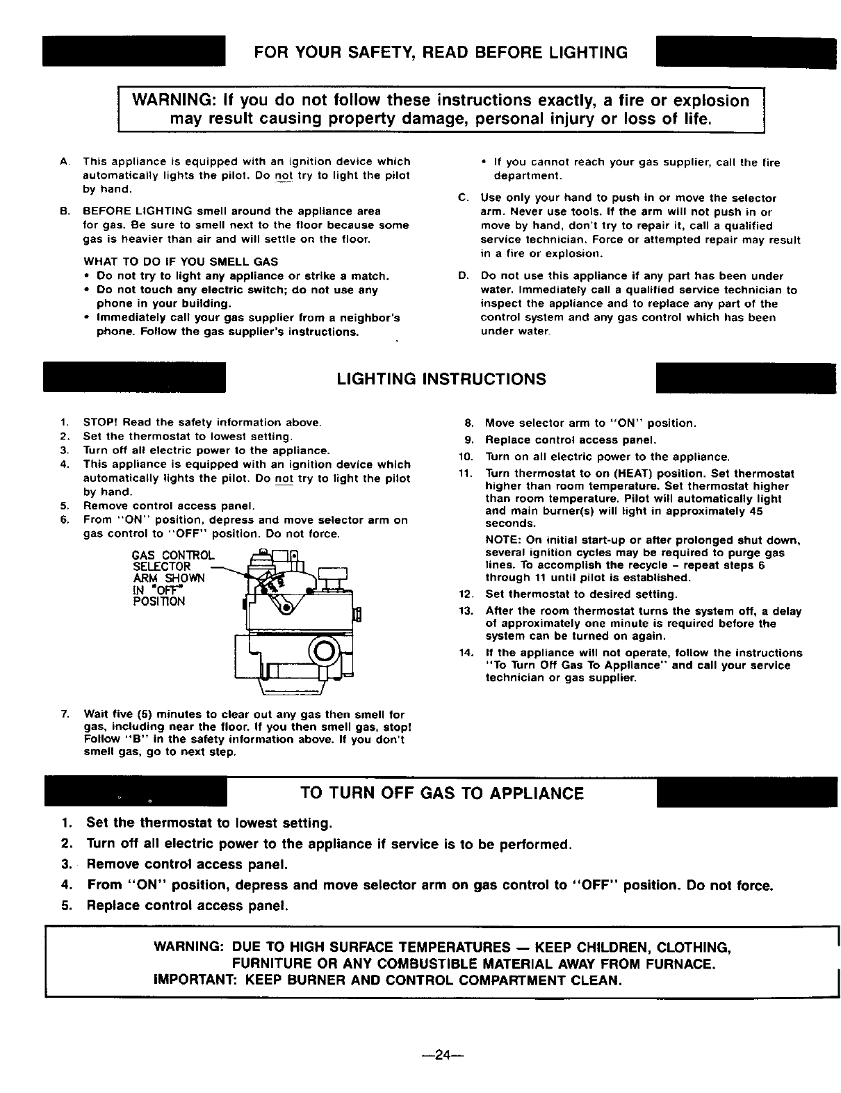
FOR YOUR SAFETY, READ BEFORE LIGHTING
WARNING: If you do not follow these instructions exactly, a fire or explosion
may result causing property damage, personal injury or loss of life.
A. This appliance is equipped with an ignition device which
automatically lights the pilot. Do not try to light the pilot
by hand.
B. BEFORE LIGHTING smell around the appliance area
for gas. Be sure to smell next to the floor because some
gas is heavier than air and will settle on the floor.
WHAT TO DO iF YOU SMELL GAS
•DO not try to light any appliance or strike a match.
•Do not touch any electric switch; do not use any
phone in your building.
•Immediately call your gas supplier from a neighbor's
phone. Follow the gas supplier's instructions.
C.
O.
•If you cannot reach your gas supplier, call the fire
department.
Use only your hand to push in or move the selector
arm. Never use tools. If the arm will not push in or
move by hand, don't try to repair it, call a qualified
service technician. Force or attempted repair may result
in a fire or explosion.
Do not use this appliance if any part has been under
water. Immediately call a qualified service technician to
inspect the appliance and to replace any part of the
control system and any gas control which has been
under water.
LIGHTING INSTRUCTIONS
1. STOP! Read the safety information above.
2. Set the thermostat to lowest setting.
3. Turn off all electric power to the appliance.
4. This appliance is equipped with an ignition device which
automatically lights the pilot. Do not try to light the pilot
by hand.
5. Remove control access panel.
6. From "ON" position, depress and move selector arm on
gas control to "OFF" position. Do not force.
GAS CON'I_OL
SELECTOR
ARM SHOWN
IN "OFF"
POSITION
7. Wait five (5) minutes to clear out any gas then smell for
gas, including near the floor. If you then smell gas, atop!
Follow "B" in the safety information above. If you don't
smell gas, go to next step.
8. Move selector arm to "ON" position.
9. Replace control access panel.
10. Turn on all electric power to the appliance.
11. Turn thermostat to on (HEAT) position. Set thermostat
higher than room temperature. Set thermostat higher
than room temperature. Pilot will automatically light
and main burner(s) will light in approximately 45
seconds.
12.
13.
14.
NOTE: On initial start-up or after prolonged shut down,
several ignition cycles may be required to purge gas
lines. To accomplish the recycle - repeat steps 6
through 11 until pilot is established.
Set thermostat to desired setting.
After the room thermostat turns the system off, a delay
of approximately one minute is required before the
system can be turned on again.
If the appliance will not operate, follow the instructions
"To Turn Off Gas To Appliance" and call your service
technician or gas supplier.
TO TURN OFF GAS TO APPLIANCE
1. Set the thermostat to lowest setting.
2. Turn off all electric power to the appliance if service is to be performed.
3. Remove control access panel.
4. From "ON" position, depress and move selector arm on gas control to "OFF" position. Do not force.
5. Replace control access panel.
WARNING: DUE TO HIGH SURFACE TEMPERATURES -- KEEP CHILDREN, CLOTHING,
FURNITURE OR ANY COMBUSTIBLE MATERIAL AWAY FROM FURNACE.
IMPORTANT: KEEP BURNER AND CONTROL COMPARTMENT CLEAN.
--24--
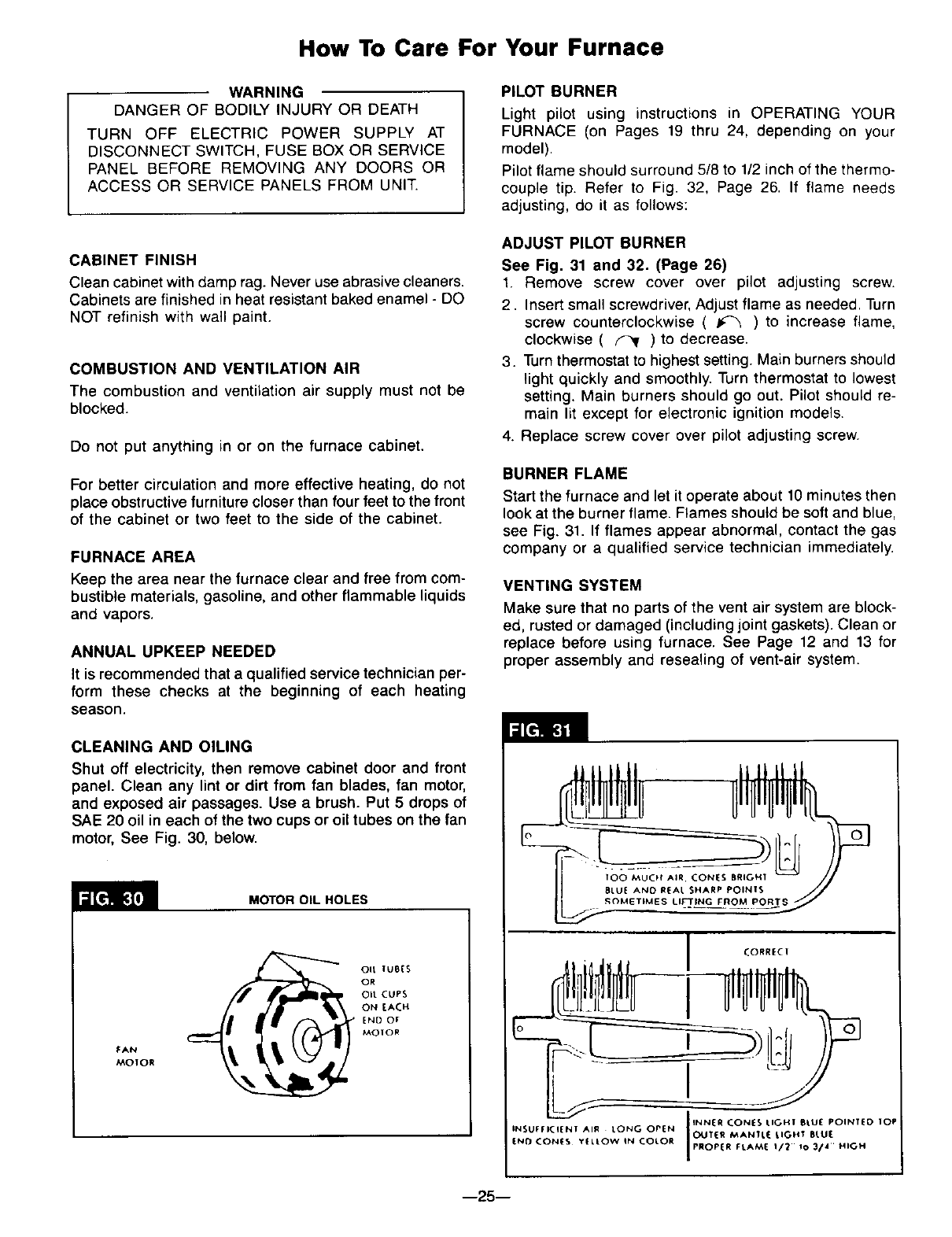
How To Care For Your Furnace
WARNING
DANGER OF BODILY INJURY OR DEATH
TURN OFF ELECTRIC POWER SUPPLY AT
DISCONNECT SWITCH, FUSE BOX OR SERVICE
PANEL BEFORE REMOVING ANY DOORS OR
ACCESS OR SERVICE PANELS FROM UNIT.
CABINET FINISH
Clean cabinet with damp rag. Never use abrasive cleaners.
Cabinets are finished in heat resistant baked enamel - DO
NOT refinish with wail paint.
COMBUSTION AND VENTILATION AIR
The combustion and ventilation air supply must not be
blocked.
Do not put anything in or on the furnace cabinet.
For better circulation and more effective heating, do not
place obstructive furniture closer than four feet to the front
of the cabinet or two feet to the side of the cabinet.
FURNACE AREA
Keep the area near the furnace clear and free from com-
bustible materials, gasoline, and other flammable liquids
and vapors.
ANNUAL UPKEEP NEEDED
It is recommended that a qualified service technician per-
form these checks at the beginning of each heating
season.
CLEANING AND OILING
Shut off electricity, then remove cabinet door and front
panel. Clean any lint or dirt from fan blades, fan motor,
and exposed air passages. Use a brush. Put 5 drops of
SAE 20 oil in each of the two cups or oil tubes on the fan
motor, See Fig. 30, below.
MOTOR OIL HOLES
FAN
MOIOR
Oft Ius{S
OR
Oft CUPS
ON EACH
END OF
MOIOR
PILOT BURNER
Light pilot using instructions in OPERATING YOUR
FURNACE (on Pages 19 thru 24, depending on your
model).
Pilot flame should surround 5/8 to 1/2 inch of the thermo-
couple tip. Refer to Fig. 32, Page 26. If flame needs
adjusting, do it as follows:
ADJUST PILOT BURNER
See Fig. 31 and 32. (Page 26)
1. Remove screw cover over pilot adjusting screw.
2. Insert small screwdriver, Adjust flame as needed. Turn
screw counterclockwise ( _) to increase flame,
clockwise ( _ ) to decrease.
3. Turnthermostat to highest setting. Main burners should
light quickly and smoothly. Turn thermostat to lowest
setting. Main burners should go out. Pilot should re-
main lit except for electronic ignition models.
4. Replace screw cover over pilot adjusting screw.
BURNER FLAME
Start the furnace and let it operate about 10 minutes then
look at the burner flame. Flames should be soft and blue,
see Fig. 31. If flames appear abnormal, contact the gas
company or a qualified service technician immediately.
VENTING SYSTEM
Make sure that no parts of the vent air system are block-
ed, rusted or damaged (including joint gaskets). Clean or
replace before using furnace. See Page 12 and 13 for
proper assembly and reseating of vent-air system.
--25--
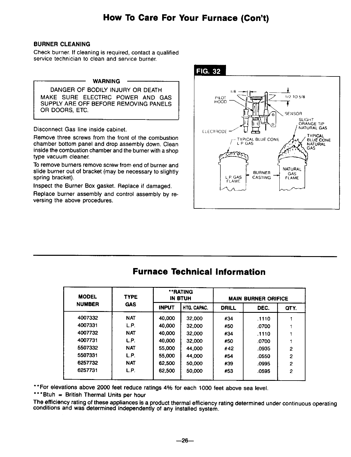
How To Care For Your Furnace (ton't)
BURNER CLEANING
Check burner. If cleaning is required, contact a qualified
service technician to clean and service burner.
WARNING
DANGER OF BODILY INJURY OR DEATH
MAKE SURE ELECTRIC POWER AND GAS
SUPPLY ARE OFF BEFORE REMOVING PANELS
OR DOORS, ETC.
Disconnect Gas line inside cabinet.
Remove three screws from the front of the combustion
chamber bottom panel and drop assembly down. Clean
inside the combustion chamber and the burner with a shop
type vacuum cleaner.
To remove burners remove screw from end of burner and
slide burner out of bracket (may be necessary to slightly
spring bracket).
Inspect the Burner Box gasket. Replace if damaged.
Replace burner assembly and control assembly by re-
versing the above procedures.
SENSOR
SLtGHT
ORANGE TIP
NATURAL GAS
ELECTnODE TYPICAL
-TYPICAL BLUE CONE ,_A /BLUE CONE
[L P GAS _,_(_l_ NATURAL
BURNER
CASTING
Furnace Technical Information
MODEL
NUMBER
4007332
4007331
4007732
4007731
5507332
5507331
6257732
6257731
TYPE
GAS
NAT
L.P.
NAT
L.P.
NAT
L.P.
NAT
L.P.
**RATING
IN BTUH
INPUT HTG.CAPAC.
32,000
32,000
32,000
32,000
44,000
44,000
5O,0OO
50,000
DRILL DEC.
#34 .1110
#50 .0700
#34 ,1110
#50 .0700
#42 .0935
#54 .0550
#39 .0995
#53 .0595
40,000
40,000
40,000
40,000
55,000
55,000
62,500
62,500
MAIN BURNER ORIFICE
QTY.
1
1
1
1
2
2
2
2
**For elevations above 2000 feet reduce ratings 4% for each 1000 feet above sea level.
***Btuh = British Thermal Units per hour
The efficiency rating of these appliances is aproduct thermal efficiency rating determined under continuous operating
conditions and was determined independently of any installed system.
--26--
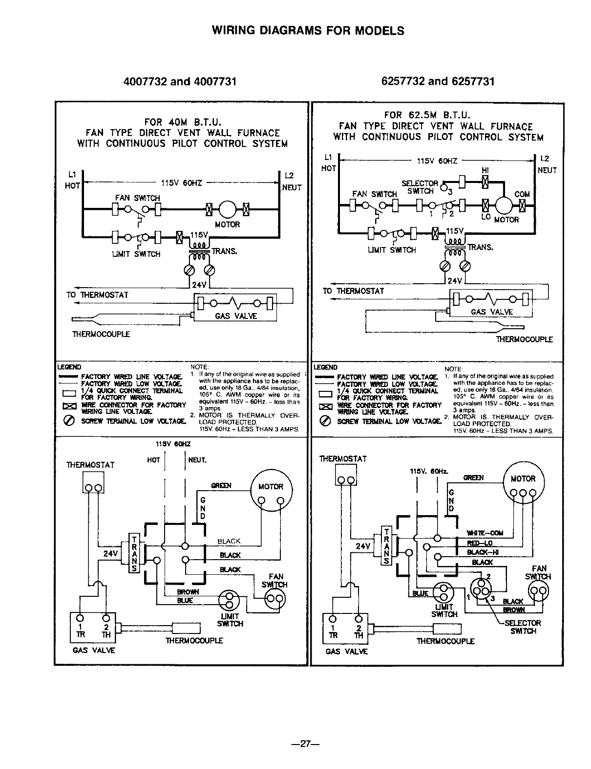
WIRING DIAGRAMS FOR MODELS
4007732 and 4007731 6257732 and 6257731
FOR 40M B.T.U.
FAN TYPE DIRECT VENT WALL FURNACE
WITH CONTINUOUS PILOT CONTROL SYSTEM
I
UMIT SWITCH' (_"I1RAN S.
_____________.___________j--HGASV_W I
THERMOCOUPLE
J_(;IE3_D NOTE:
m FACTC_Y _lINE _OLTAGE, 1 Ifanyoftheoriginalwireassupplied
-- FACTORY _LOW VOLTAGF.. with the appliance has to be replac-
11/_4 _CONNECT "i_MINAL ed, use only 18 Ga., 4/64 insulation,
FACI'(_T" _RING* 105 °C. AWM copper wire or its
_tllRE CO_CTOI_ F01t FAC_I101_Y equivalent 115V- 60Hz -lessthan
3 amps
_NG LINE VOLTAGE. 2 MOTOR IS THERMALLY OVER-
_ _ LOW V0LTAilI_ LOAD PROTECTED
115%L60Hz - LESS THAN 3 AMPS
THERMOSTAT
r
•1
L
GAS VALVE
115V 60H7.
HOTI ]NEUT"
A
_ THERMC¢-.,'_N.IPLE
FOR 62.5M B.T.U.
FAN TYPE DIRECT VENT WALL FURNACE
WITH CONTINUOUS PILOT CONTROL SYSTEM
L1 __ 115v 60HZ ,L2
HOT| Hf NEUT
TOTHERMOSTAT _ [_ GAS VALVE +
L___
THERMOCOUPLE
LEGEND NOTE:
m FACTORy _UNE VOLTAGE. 1. Ifanyoftheoriginalwiteassupplied
-- FAI_[IO_y _LOW "YOLTAG_* with the appliance has to be replac-
1/4. QUICKCONNECTT_MZNAL ed, use only 18Ga., 4/64 insulation,
f'(_ FAt_O_ " _R]NG. 105° CAWM copper wire or ils
•f_R£ CONNECTOR FOR FACTORY equivalent 115v -60Hz - less than
WIRING LINE VOLTAGE. 3 amps
MOTOR IS THERMALLY OVER-
_ _INAL LOW VOLTAGE. 2. LOAD PROTECTED
115V.60Hz -LESS THAN 3 AMPS.
B_CK
BLiU_
BI.gE_K'O_ F(__
UMIT
_ s_Ta_
THERMOSTAT
f
THERMOCOUPLE
G_ V_
--27--
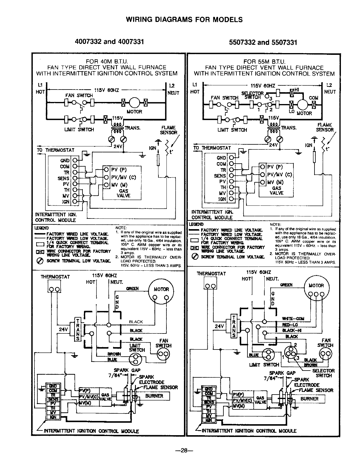
WIRING DIAGRAMS FOR MODELS
4007332 and 4007331 5507332 and 5507331
FOR 40M B.T.U.
FAN TYPE DIRECT VENT WALL FURNACE
WITH INTERMtTFENT IGNITION CONTROL SYSTEM
ul lu
HOTi_ 115VS0HZ -I N_.UT
_ O- --
/ TR _PV(P) TL
/SF_NSO- PV,,1WV(c) ,--
/ PV O, Mv(u)
INTERMII"R_T IGN.
CONTROL MODULE
LEGI0_ID
_FACTORy _RED LINEVOLTAQF-
-- FACTQ_qY_LOWVOLTAGE.
I--3 1/4 QUICKCON_C'r TERM1NAL
FOR FACTORYI_NG.
WIRECONNECTORFOR FACTORY
_li_lP- LINEV(_.TAaE,
_ _INAL LOW VOLTAGE.
NOTE:
1. If any of the original wire as supplied
with the appliance has to be replec-
ed, use only 18 Ga. 4/64 insulation,
105= C AWM copper wire or ils
equivalent 115V - 60Hz - less Ihan
3 amps
2, MOTOR IS THERMALLY OVER=
LOAD PROTECTED,
115V, 60Hz -LESS THAN 3 AMPS
1HERMOSTAT 115V 60HZ
HOT NEUT.
FAN
FOR 55M BT.U.
FAN TYPE DIRECT VENT WALL FURNACE
WITH INTERMITI-ENT IGNITION CONTROL SYSTEM
1.1 |. 115V8ONZ .| L2
HOT ! S_f)R _|NEUT
L_r_115V II
T.____.__T. -_eJ....,o ru_
LIMIT SWITCH ._ m,_,a, SE_ISOR
GND
s_so_ ?-ioFv/_v(c) "--
PV Ol--- .-'r-lOIMV (_)
THOl_ IF" cAs
MV (Z)-_ -'J I VALV_
ION___ --
IN'W_RMII"TF_NTIGN.
CONTROLMODULE
_L_E_FACTORY_ lINE VOLTA_E,
-- YA_ _ LOWVOLTAGE.
1/4 QUICKCONNECT
FORF_Y
_CONNECqORFOR FACTORY
tiRiNg MNE VOLTA_..
(d_ _ _ LOWVOLTAGE.
NOTE:
1. If any of the original wire as supplied
with the opp_lence has to b_ replec*
ed, use only 18 Ga., 4/64 insulation,
105° C. AWM copper w=re ot its
equivalent 115V - 60Hz. - less than
3 amps.
2. MOTOR IS THERMALLY OVER-
LOAD PROTECTED.
115M 60Hz - LESS THAN 3 AMPS
31"IERMOSTAT 115V 60HZ
HOT I NEUT.
_.-c_
--28--
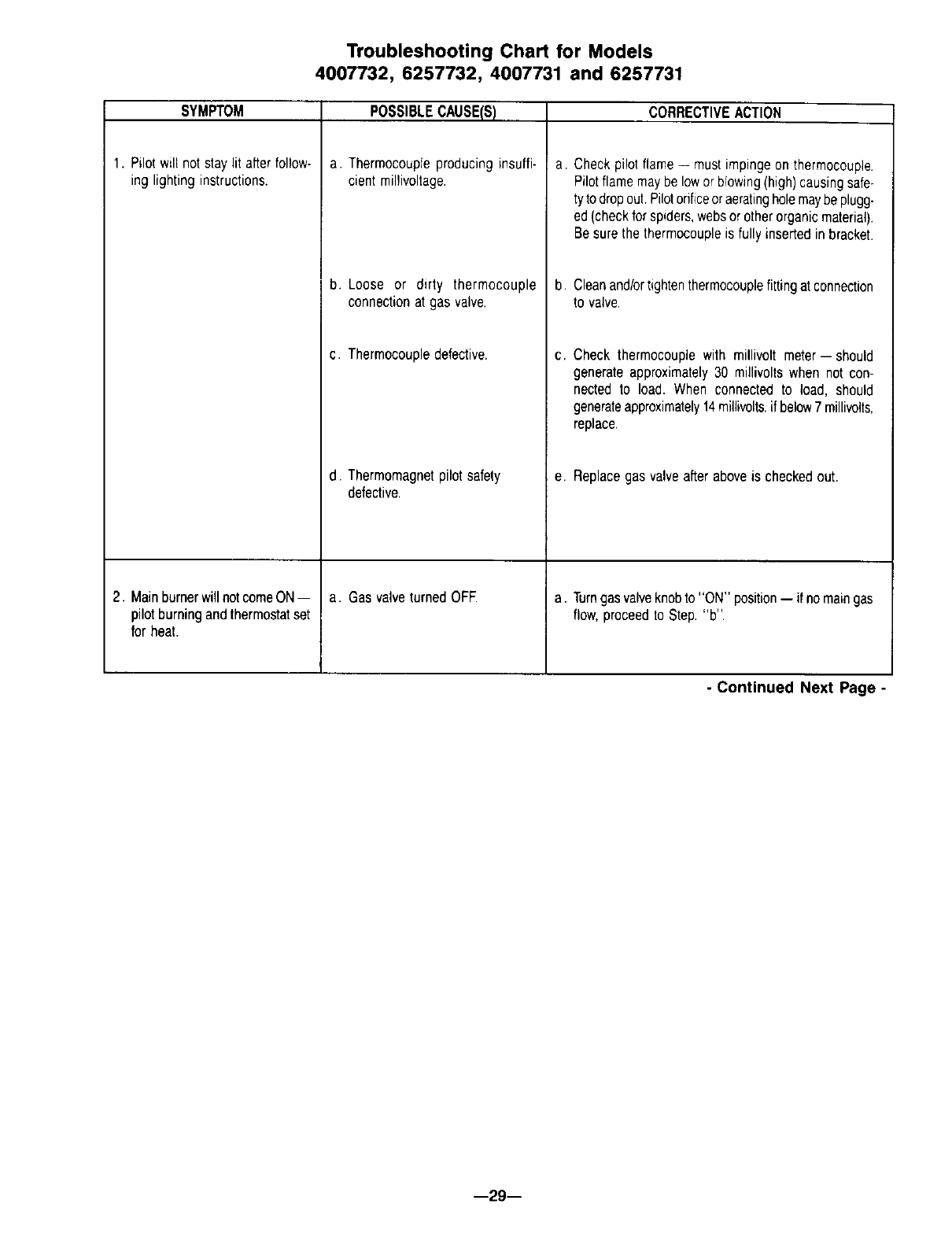
Troubleshooting Chart for Models
4007732, 6257732, 4007731 and 6257731
SYMPTOM
1. Pilotwill not staylit afterfollow-
ing lighting instructions.
2. MainburnerwillnotcomeON--
pilotburningandthermostatset
for heat.
POSSIBLECAUSE(S)
a. Thermocoupleproducinginsuffi-
cientmillivoltage.
b. Loose or dirty thermocouple
connectionat gas valve.
c. Thermocoupledefective.
d. Thermomagnetpilotsafety
defective.
a. Gas valveturnedOFE
CORRECTIVEACTION
a. Checkpilot flame-- mustimpingeon thermocouple.
Pilotflamemaybe lowor blowing(high)causingsafe-
tytodropout.Pilotorificeoraeratingholemaybeplugg-
ed(checkforspiders,websorotherorganicmaterial).
Besurethe thermocoupleis fullyinsertedinbracket.
b. Cleanand/ortightenthermocouplefittingatconnection
to valve
C, Check thermocouplewith millivolt meter--should
generateapproximately30 millivoltswhen not con-
nected to load. When connectedto load, should
generateapproximately14millivolts,if below7 millivolts,
replace.
e. Replacegasvalveafteraboveis checkedout.
a. Turngasvalveknobto "ON" position-- if nomaingas
flow,proceedto Step."b".
-Continued Next Page -
--29--
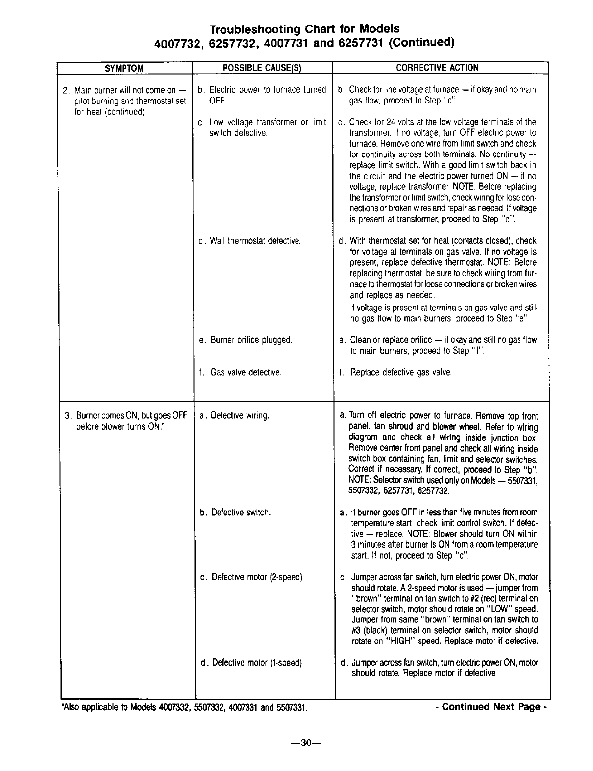
Troubleshooting Chart for Models
4007732, 6257732, 4007731 and 6257731 (Continued)
SYMPTOM
2 Mainburnerwill notcomeon --
pilotburningandthermostatset
for heat (continued)
3. BurnercomesON,butgoesOFF
beforeblowerturns ON."
POSSIBLECAUSE(S)
b Electric powerto furnaceturned
OFE
c. Low voltagetransformeror limit
switchdefective
d. Wallthermostatdefective.
e. Burnerorificeplugged.
f. Gas valvedefective.
a. Defectivewiring.
b. Defectiveswitch.
c. Defectivemotor(2-speed)
d. Defectivemotor(t-speed).
CORRECTIVEACTION
b. Checkfor linevoltageatfurnace-- if okayandnomain
gas flow,proceedto Step"c".
C. Checkfor 24volts at the lowvoltageterminalsof the
transformer.If no voltage,turn OFFelectricpowerto
furnace.Removeonewirefromlimitswitchandcheck
for continuityacrossbothterminals.No continuity--
replacelimitswitch.Witha goodlimitswitchbackin
the circuit andthe electric powerturnedON-- if no
voltage,replacetransformer.NOTE:Beforereplacing
thetransformerorlimitswitch,checkwiringforlosecon-
nectionsorbrokenwiresandrepairasneeded.Ifvoltage
is presentat transformer,proceedto Step "d".
d. Withthermostatsetfor heat(contactsclosed),check
for voltageat terminalson gasvalve.If no voltageis
present,replacedefectivethermostat.NOTE:Before
replacingthermostat,besureto checkwiringfromfur-
nacetothermostatforlooseconnectionsorbrokenwires
andreplaceas needed.
Ifvoltageis presentat terminalsongasvalveandstill
no gas flowto mainburners,proceedto Step"e".
e. Cleanor replaceorifice-- if okayandstillnogasflow
to mainburners,proceedto Step "f".
f. Replacedefectivegas valve.
a. Turnoff electricpowerto furnace.Removetop front
panel,fan shroudand blowerwheel.Referto wiring
diagram and check all wiring inside junction box.
Removecenterfrontpanelandcheckall wiringinside
switchbox containingfan, limitandselectorswitches.
Correctif necessary.If correct,proceedto Step"b".
NOTE:SelectorswitchusedonlyonModels-- 5507331,
5507332,6257731,6257732.
a. IfburnergoesOFFinlessthanfiveminutesfromroom
temperaturestart,checklimitcontrolswitch.If defec-
tive-- replace.NOTE:Blowershouldturn ON within
3 minutesafterburneris ONfromaroomtemperature
start.If not,proceedto Step"c".
C. Jumperacrossfanswitch,turnelectricpowerON,motor
shouldrotate.A2-speedmotoris used-- jumperfrom
"brown" terminalonfanswitchto#2(red)terminalon
selectorswitch,motorshouldrotateon "LOW"speed.
Jumperfromsame"brown"terminalon fanswitchto
#3 (black)terminalon selectorswitch,motorshould
rotateon "HIGH" speed.Replacemotorif defective.
d. Jumperacrossfanswitch,turnelectricpowerON,motor
shouldrotate.Replacemotorif defective.
*Alsoapplicableto Models4007332,5507332,4007331and5507331. -Continued Next Page -
--30--
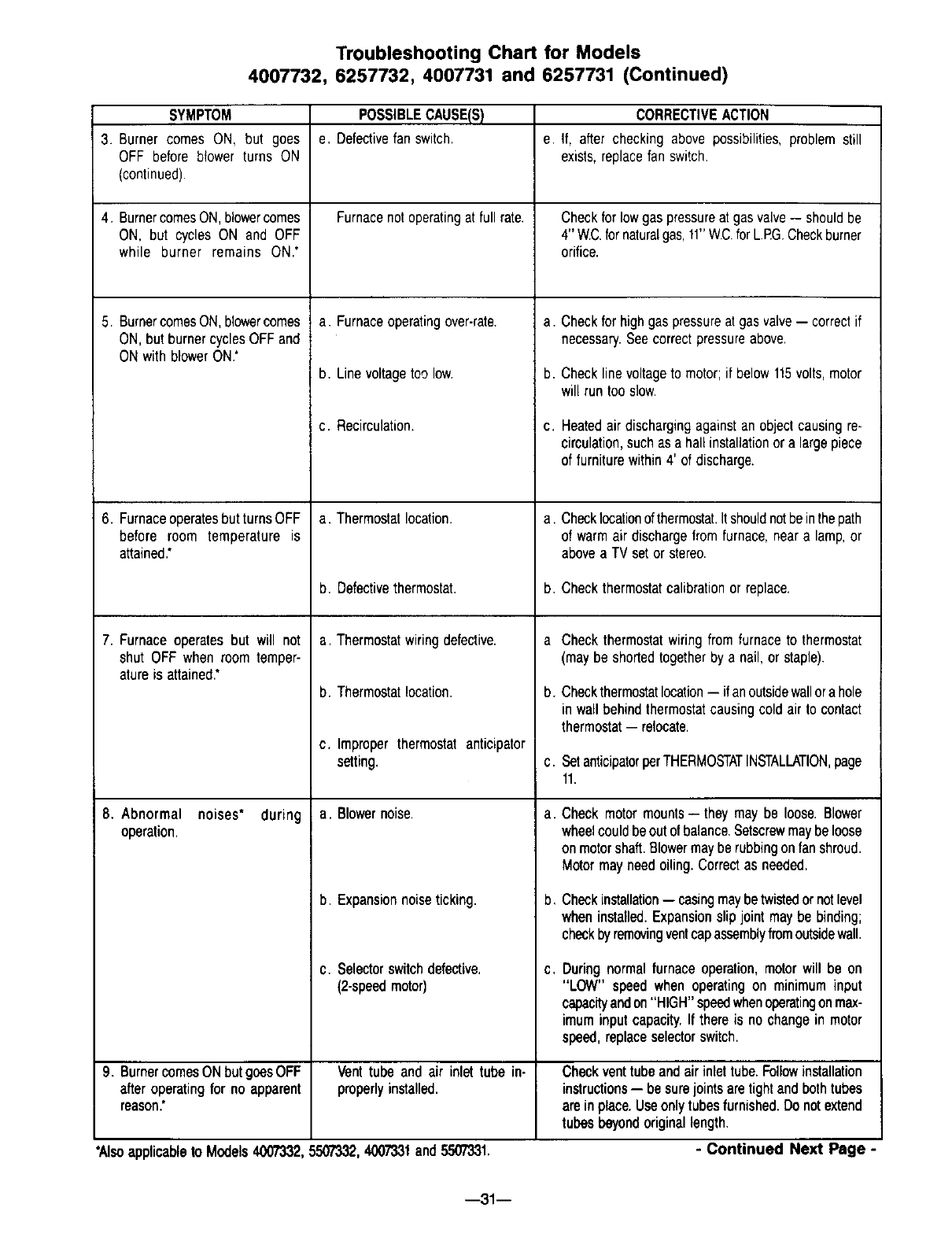
Troubleshooting Chart for Models
4007732, 6257732, 4007731 and 6257731 (Continued)
SYMPTOM
3. Burner comes ON, but goes
OFF before blower turns ON
(continued).
4. BurnercomesON,blowercomes
ON, but cycles ON and OFF
while burner remains ON.*
5. BurnercomesON,blowercomes
ON,but burnercyclesOFFand
ON with blowerON.*
6. FurnaceoperatesbutturnsOFF
before room temperature is
attained.*
7. Furnaceoperatesbut will not
shut OFF whenroom temper-
atureis attained.*
8. Abnormal noises* during
operation.
POSSIBLECAUSE(S)
e. Detectivefan switch.
Furnacenotoperatingat full rate.
a. Furnaceoperatingover-rate.
b. Linevoltagetoo low.
c. Recirculation.
a. Thermostatlocation.
b. Defectivethermostat.
a, Thermostatwiringdefective.
b. Thermostatlocation.
c. Improper thermostat anticipator
setting.
a. Blowernoise.
b. Expansionnoiseticking.
c. Selectorswitchdefective,
(2-speedmotor)
CORRECTIVEACTION
e. If, after checking above possibilities,problem still
exists,replacefan switch
Checkfor lowgas pressureat gasvalve-- shouldbe
4" W£. fornaturalgas,11"W.C.forL.RG.Checkburner
orifice.
a. Checkfor highgas pressureat gasvalve-- correctif
necessary.Seecorrectpressureabove.
b. Checklinevoltageto motor;if below115volts,motor
will runtoo slow.
I c. Heatedair dischargingagainstan objectcausingre-
circulation,suchasa hallinstallationora largepiece
of furniturewithin4' of discharge.
a. Checklocationofthermostat.Itshouldnotbeinthepath
of warmairdischargefrom furnace,neara lamp,or
abovea TV set orstereo.
b. Checkthermostatcalibrationor replace.
a Check thermostatwiringfrom furnaceto thermostat
(maybe shortedtogetherby a nail,or staple).
b. Checkthermostatlocation-- if anoutsidewallorahole
in wallbehindthermostatcausingcold airto contact
thermostat-- relocate.
c. SetanticipatorperTHERMOSTATINSTALLATION,page
11.
a. Check motormounts-- they maybe loose.Blower
wheelcouldbeoutof balance.Setscrewmaybeloose
on motorshaft.Blowermayberubbingonfanshroud.
Motormayneedoiling.Correctas needed,
b, Checkinstallation-- casingmaybetwistedornotlevel
wheninstalled.Expansionslip joint maybe binding;
checkbyremovingventcapassemblyfromoutsidewall.
C, Duringnormalfurnaceoperation,motorwill be on
"LOW" speedwhenoperatingon minimum input
capacityandon"HIGH"speedwhenoperatingonmax-
imuminput capacity,If there is no changein motor
speed,replaceselectorswitch,
9. BurnercomesONbutgoesOFF Vent tube and air inlet tube in- Checkventtube andair inlet tube.Followinstallation
afteroperatingfor no apparent properlyinstalled, instructions-- besurejointsaretightandbothtubes
reason.* areinplace.Useonly tubesfurnished.Do notextend
tubes beyondoriginallength.
*Alsoapplicableto Models4(Y)7332,550T332,4007331and5,507331. - Continued Next Page
--31 --
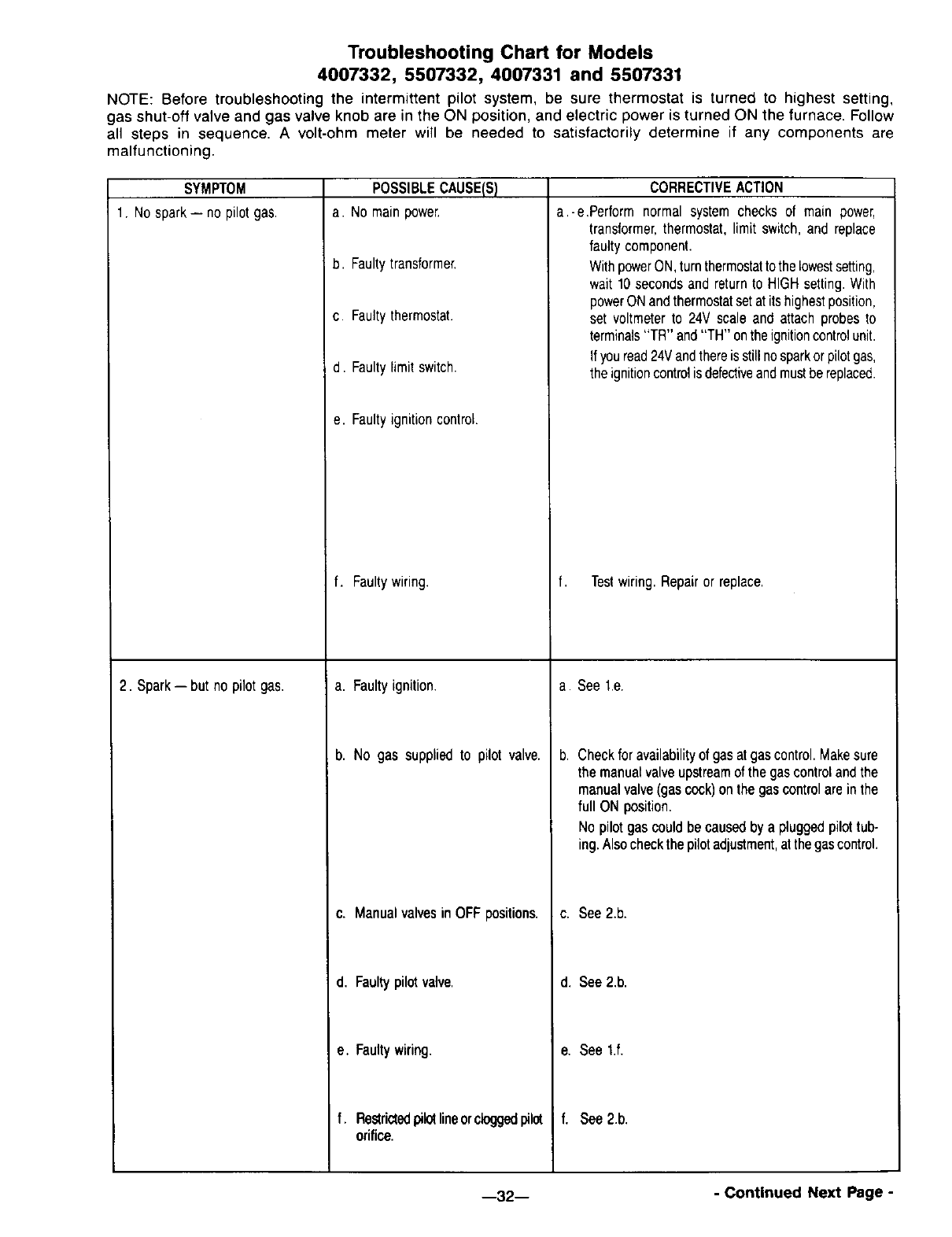
Troubleshooting Chart for Models
4007332, 5507332, 4007331 and 5507331
NOTE: Before troubleshooting the intermittent pilot system, be sure thermostat is turned to highest setting,
gas shut-off valve and gas valve knob are in the ON position, and electric power is turned ON the furnace. Follow
all steps in sequence. A volt-ohm meter will be needed to satisfactorily determine if any components are
malfunctioning.
SYMPTOM
1. Nospark-- no pilot gas.
2. Spark-- but no pilot gas.
POSSIBLECAUSE(S)
a. Nomainpower.
b. Faultytransformer,
c. Faultythermostat.
d. Faultylimit switch.
e. Faultyignitioncontrol.
f. Faultywiring.
a. Faultyignition.
b. No gas suppliedto pilot valve.
c. Manualvalvesin OFFpositions.
d. Faultypilot valve.
CORRECTIVEACTION
a.-e.Perform normal system checks of main power,
transformer,thermostat,limit switch,and replace
faulty component.
WithpowerON,turnthermostattothelowestsetting,
wait 10secondsandreturnto HIGHsetting.With
powerONandthermostatsetat itshighestposition,
set voltmeterto 24V scale and attach probesto
terminals"TR" and"TH" ontheignitioncontrolunit.
Ifyouread24Vandthereisstillnosparkorpilotgas,
the ignitioncontrolisdefectiveandmustbereplaced.
f. Testwiring. Repairor replace.
a. See1.e.
b. Checkfor availabilityof gas atgascontrol.Makesure
the manualvalveupstreamof thegas controlandthe
manualvalve(gascock)on the gascontrolarein the
full ON position.
No pilot gas couldbecausedby a pluggedpilottub-
ing.Alsocheckthepilotadjustment,atthegascontrol.
c. See2.b.
d. See2b.
e. Faultywiring.
f. Restrictedpilotlineorcloggedpilot
orifice.
e. See t.f.
' f. See2.b.
--32-- - Continued Next Page -
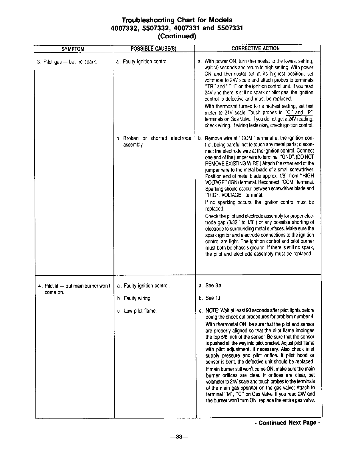
Troubleshooting Chart for Models
4007332, 5507332, 4007331 and 5507331
(Continued)
SYMPTOM
3. Pilot gas-- but no spark.
4. Pilotlit-- but mainburnerwon't
comeon.
POSSIBLECAUSE(S)
a. Faultyignitioncontrol
b. Broken or shorted electrode
assembly.
a. Faultyignitioncontrol.
b. Faultywiring.
c. Lowpilot flame.
CORRECTIVEACTION
a, WithpowerON,turnthermostatto the lowestsetting,
wait10secondsandreturnto highsetting.Withpower
ON and thermostatset at its highestposition, set
voltmeterto 24Vscaleandattachprobesto terminals
"TR" and"TH" ontheignitioncontrolunit.Ifyouread
24Vandthereis stillnosparkor pilotgas,the ignition
controlis defectiveand mustbe replaced.
Withthermostatturnedto its highestsetting,settest
meterto 24V scale.Touchprobesto "C" and "P"
terminalsonGasValve.Ifyoudo notgeta 24Vreading,
checkwiring,Ifwiringtestsokay,checkignitioncontrol.
b. Removewireat "COM" terminalat the ignitioncon-
trol,beingcarefulnotto touchanymetalparts;discon-
nectthe electrodewireattheignitioncontrol.Connect
oneendofthejumperwireto terminal"GND",(DONOT
REMOVEEXISTINGWIRE.)Attachtheotherendofthe
jumperwireto the metalbladeof a smallscrewdriver.
Positionendof metalbladeapprox,1/8"from"HIGH
VOLTAGE"(IGN)terminal.Reconnect"COM"terminal.
Sparkingshouldocccurbetweenecrev,_lriverbladeand
"HIGH VOLTAGE"terminal.
If no sparkingoccurs,the ignition controlmust be
replaced.
Checkthepilotandelectrodeassemblyforprobereleo
trode gap (3/32" to 1/8") or any possibleshortingof
electrodetosurroundingmetalsurfaces.Makesurethe
sparkignitorandelectrodeconnectionsto the ignition
controlaretight. The ignitioncontrolandpilot burner
mustbothbechassisground.If thereis stillno spark,
the pilot and electrodeassemblymust be replaced.
a. See3.a.
b. See 1.f,
C. NOTE:Waitatleast90secondsafterpilotlightsbefore
doingthecheckoutproceduresforproblemnumber4.
WiththermostatON,be surethatthepilotandsensor
areproperlyalignedso thatthe pilot flameimpinges
thetop 5/8inchof thesensor.Besurethatthe sensor
ispushedallthewayintopilotbracket.Adjustpilotflame
with pilot adjustment,if necessary.Alsocheckinlet
supply pressureand pilotorifice, If pilot hood or
sensorisbent,thedefectiveunitshouldbereplaced.
Ifmainburnerstillwon'tcomeON,makesurethemain
burner orifices are clear. If orificesare clear, set
voltmeterto24Vscaleandtouchprobestotheterminals
of the maingas operatoron the gasvalve;Attachto
terminal"M", "C" onGasValve.If youread24',/and
theburnerwon'tturnON,replacetheentiregasvalve.
- Continued Next Page -
--33--
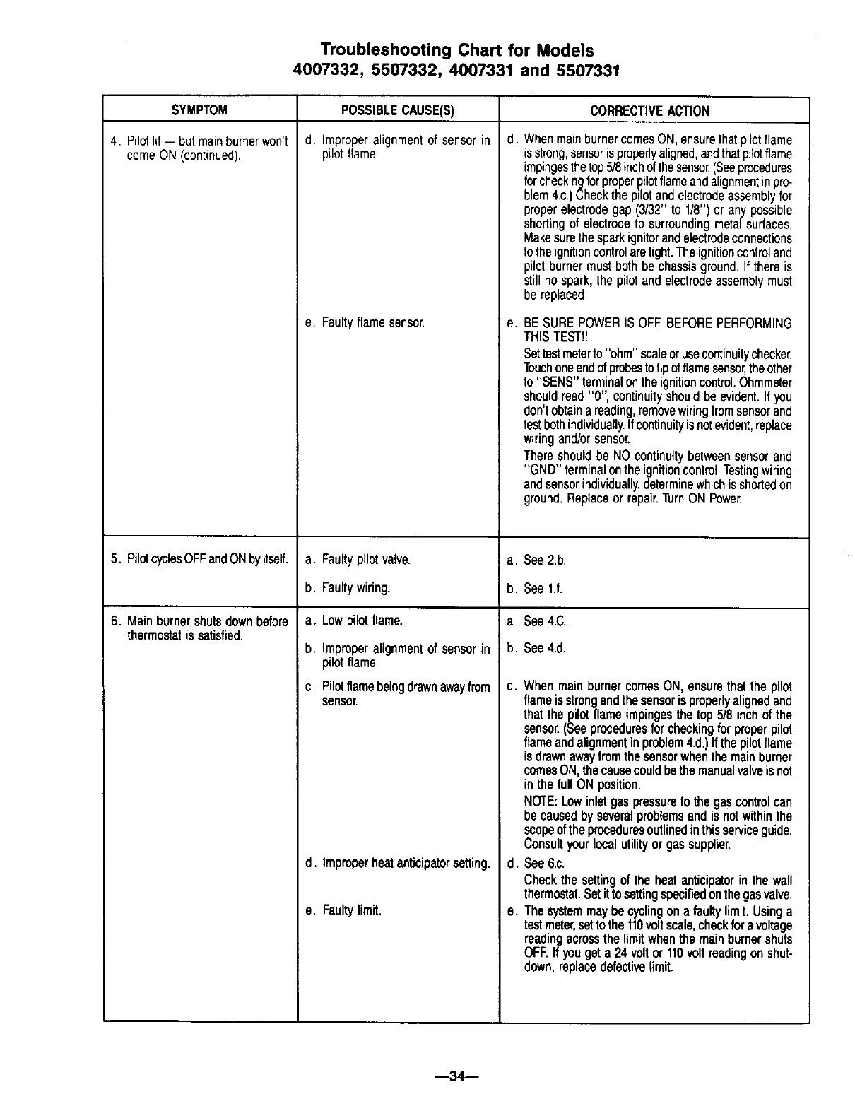
Troubleshooting Chart for Models
4007332, 5507332, 4007331 and 5507331
SYMPTOM
4. Pilotlit -- but mainburnerwon't
comeON(continued).
POSSIBLE CAUSE(S)
d, Improperalignment of sensor in
pilot flame.
e. Faultyflamesensor.
CORRECTIVEACTION
a. Faultypilotvalve.
b. Faultywiring.
a. Lowpilot flame.
b. Improperalignmentof sensorin
pilotflame.
c. Pilotflamebeingdrownawayfrom
sensor.
d. WhenmainburnercomesON,ensurethatpilotflame
is strong,sensorisproperlyaligned,andthatpilotflame
impingesthetop5/8inchofthesensor(Seeprocedures
forcheckingforproperpilotflameandalignmentinpro-
blem4.c.)Checkthe pilotandelectrodeassemblyfor
properelectrodegap(3/32"to 1/8") or any possible
shortingof electrodeto surroundingmetalsurfaces.
Makesurethe sparkignitorandelectrodeconnections
tothe ignitioncontrolaretight.Theignitioncontroland
pilot burnermustbothbe chassisground.If thereis
still no spark,the pilotand electrodeassemblymust
be replaced.
e, BE SUREPOWERIS OFF,BEFOREPERFORMING
THISTEST_!
Settestmeterto "ohm"scaleorusecontinuitycheeke_
Touchoneendofprobestotipofflamesensor,theother
to "SENS"terminalontheignitioncontrol.Ohmmeter
shouldread"0", continuityshouldbe evident.If you
don'tobtainareading,removewiringfromsensorand
testbothindividually.Ifcontinuityis notevident,replace
wiringand/orsensor.
Thereshouldbe NO continuitybetweensensorand
"GND" terminalonthe ignitioncontrol.Testingwiring
andsensorindividually,determinewhichis shortedon
ground.Replaceor repair.TurnON Power.
5. PilotcyclesOFFandONbyitself, a. See2.b.
b. See l.f.
6. Mainburnershutsdownbefore a. See4.C.
thermostatis satisfied. b. See4.d.
d. Improperheatanticipatorsetting.
e. Faultylimit.
c. WhenmainburnercomesON,ensurethatthe pilot
flameisstrongandthe sensoris properlyalignedand
that the pilot flameimpingesthe top 5/8 inchof the
sensor.(Seeproceduresfor checkingfor properpilot
flameandalignmentin problem4.d.)Ifthepilotflame
is drawnawayfromthe sensorwhenthe mainburner
comesON,the causecouldbethemanualvalveis not
in the full ON position.
NOTE:Lowinletgas pressureto the gas controlcan
be causedbyseveralproblemsandis notwithinthe
scopeoftheproceduresoutlinedinthisserviceguide.
Consultyourlocalutilityor gassupplier.
d. see 6.c.
Checkthe settingof the heatanticipatorin the wall
thermostat,Setitto settingspecifiedonthegasvalve,
e. Thesystemmaybecyclingona faultylimit.Usinga
testmeter,settothe110voltscale,checkfor avoltage
readingacrossthe limitwhenthemainburnershuts
OFF.If yougeta 24 voltor110voltreadingonshut-
down,replacedefectivelimit.
--34---
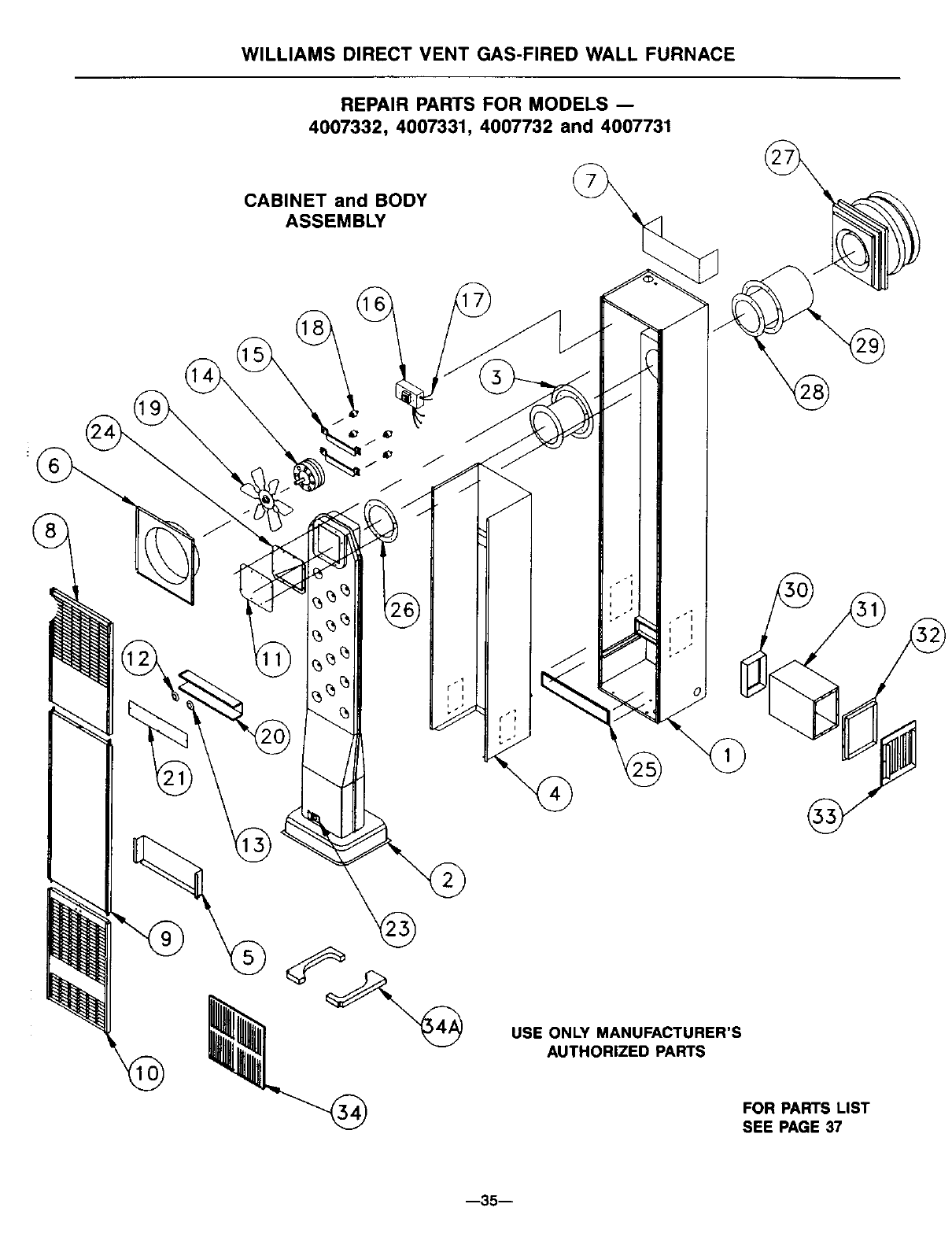
WILLIAMS DIRECT VENT GAS-FIRED WALL FURNACE
REPAIR PARTS FOR MODELS --
4007332, 4007331, 4007732 and 4007731
CABINET and BODY
ASSEMBLY
%
USE ONLY MANUFACTURER'S
AUTHORIZED PARTS
FOR PARTS LIST
SEE PAGE 37
--35--
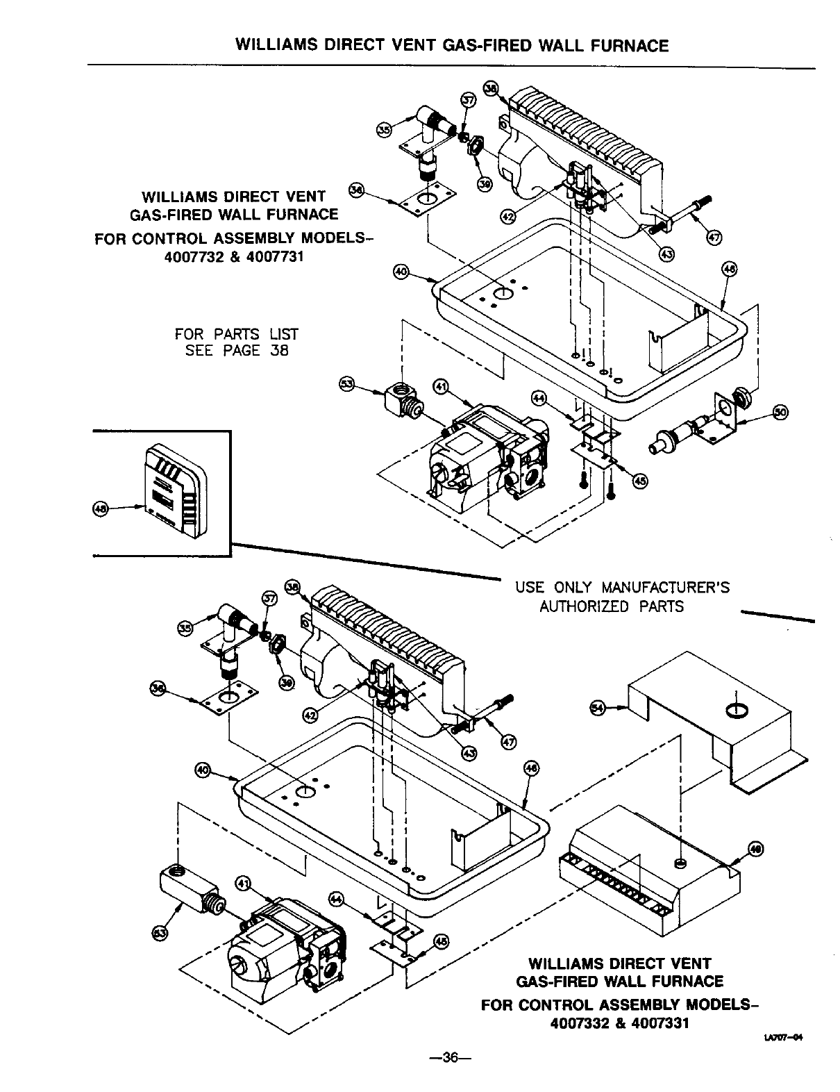
WILLIAMS DIRECT VENT GAS-FIRED WALL FURNACE
WILLIAMS DIRECT VENT
GAS-FIRED WALL FURNACE
FOR CONTROL ASSEMBLY MODELS-
4007732 & 4007731
FOR PARTS LIST
SEE PAGE 38 I
USE ONLY MANUFACTURER'S
AUTHORIZED PARTS
I •
!
--36--
WILLIAMS DIRECT VENT
GAS-FIRED WALL FURNACE
FOR CONTROL ASSEMBLY MODELS-
4007332 & 4007331
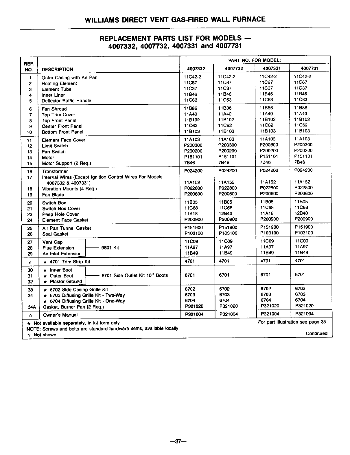
WILLIAMS DIRECT VENT GAS-FIRED WALL FURNACE
REPLACEMENT PARTS LIST FOR MODELS --
4007332, 4007732, 4007331 and 4007731
REF.
NO.
1
2
3
4
5
6
7
8
9
10
11
12
13
14
15
16
17
DESCRIPTION
Outer Casing with Air Pan
Heating Element
Element Tube
Inner Liner
Deflector Baffle Handle
Fan Shroud
Top Trim Cover
Top Front Panel
Center Front Panel
Bottom Front Panel
Element Face Cover
Limit Switch
Fan Switch
Motor
Motor Support (2 Req.)
Transformer
4007332
11 C42-2
11C67
11C37
11B46
11C63
11B86
11A40
11B102
11C62
11B103
11A103
P200300
P200200
P151101
7B46
P024200
11A152
18 P022800
19 P200600
20 11B05
21 11C68
23 11A18
24 P200900
25 P151900
26 P103100
27 11C09
28 11A07
29 11B49
,_ 4701
3O
31 6701
32
Internal Wires (Except Ignition Control Wires For Models
4007332 & 4007331)
Vibration Mounts (4 Req.)
Fan Blade
Switch Box
Switch Box Cover
Peep Hole Cover
Element Face Gasket
Air Pan Tunnel Gasket
Seal Gasket
Vent Cap
Flue Extension -- 9801 Kit
Air Inlet Extension
,it 4701 Trim Strip Kit
* Inner Boot
* Outer Boot -- 6701 Side Outlet Kit 10" Boots
* Plaster Ground
6702 Side Casing Grille Kit
* 6703 Diffusing Grille Kit - Two-Way
* 6704 Diffusing Grille Kit -One-Way
Gasket, Burner Pan (2 Req.)
Owner's Manual
PART NO. FOR MODEL:
4007732 4007331
11C42-2 11C42-2
11C67 11C67
11C37 11C37
11B46 11B46
11C63 11C63
11B86 11B86
11A40 11A40
11B102 11B102
11C62 11C62
11B103 11B103
11A103 11A103
P200300 P200300
P200200 P200200
P151101 P151101
7B46 7B46
P024200 P024200
11A152 11A152
P022800 P022800
P200600 P200600
11B05 11B05
11C68 11C68
12B40 11A18
P200900 P200900
P151900 P151900
P103100 P103100
11C09 11C09
11A97 11A97
11B49 11B49
4701 4701
6701
33 6702 6702
34 6703 6703
6704 6704
34A P321020 P321020
._ P321004 P321004
* Not available separately, in kit form only
NOTE: Screws and bolts are standard hardware items, available locally.
Not shown. Continued
4007731
11C42-2
11C67
11C37
11B46
11C63
11B86
11A40
11B102
11C62
11B103
1tA103
P200300
P200200
F151101
7B46
P024200
11A152
P022800
P200600
11B05
11C68
12B40
P200900
P151900
P103100
tlC09
11A97
11B49
4701
6701 6701
6702 6702
6703 6703
6704 6704
P321020 P321020
P321004 P321004
For paM illu_ration see page 35,
--37--
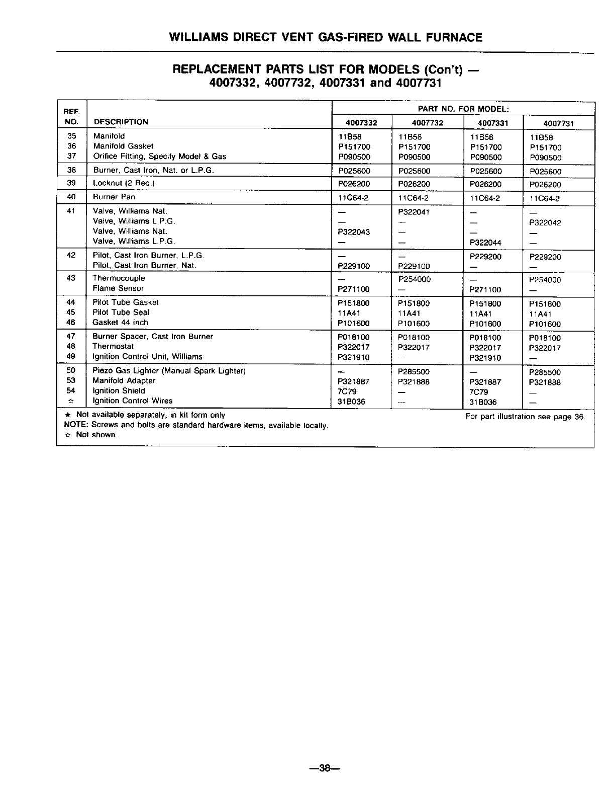
WILLIAMS DIRECT VENT GAS-FIRED WALL FURNACE
REPLACEMENT PARTS LIST FOR MODELS (Con't) --
4007332, 4007732, 4007331 and 4007731
REF.
NO.
35
36
37
38
39
40
4007332
11S58
P151700
P090500
P025600
P026200
11C64-2
DESCRIPTION
Manifold
Manifold Gasket
Orifice Fitting, Specify Model & Gas
Burner, Cast Iron, Nat. or L.P.G.
Locknut (2 Req.)
Burner Pan
Valve, Williams Nat.
Valve, Williams L.P.G,
Valve, Williams Nat.
Valve, Williams L.P.G.
Pilot, Cast Iron Burner, L.P,G.
Pilot, Cast Iron Burner, Nat.
Thermocouple
Flame Sensor
Pilot Tube Gasket
Pilot Tube Seal
Gasket 44 inch
Burner Spacer, Cast Iron Burner
Thermostat
Ignition Control Unit, Williams
Piezo Gas Lighter (Manual Spark Lighter)
Manifold Adapter
Ignition Shield
Ignition Control Wires
4007731
11B58
P151700
P090500
P025600
P026200
11C64-2
PART NO. FOR MODEL:
4007732 4007331
11B58 11B58
P151700 P151700
P090500 P090500
P025600 P025600
P026200 P026200
11C64-2 11C04-2
P322041
-- P322044
-- P229200
P229100
P254000
-- P271100
P151800 P151000
11A41 11A41
P101600 P101600
P018100 P018100
P322017 P322017
-- P321910
P285500
P321888 P321887
-- 7C79
-- 31 B036
41 m _
-- P322042
P322043
42 -- P229200
P229100
43 -- P254000
P271100
44 P151800 P151800
45 11A41 11A41
46 P101600 P101600
47 P018100 P018100
48 P322017 P322017
49 P321910 --
50 -- P285500
53 P321887 P321808
54 7C79 --
31B036 --
Not available separately, in kit form only For pa_ illustration see page 36.
NOTE: Screws and bolts are standard hardware items, available locally.
Not shown.
--38--
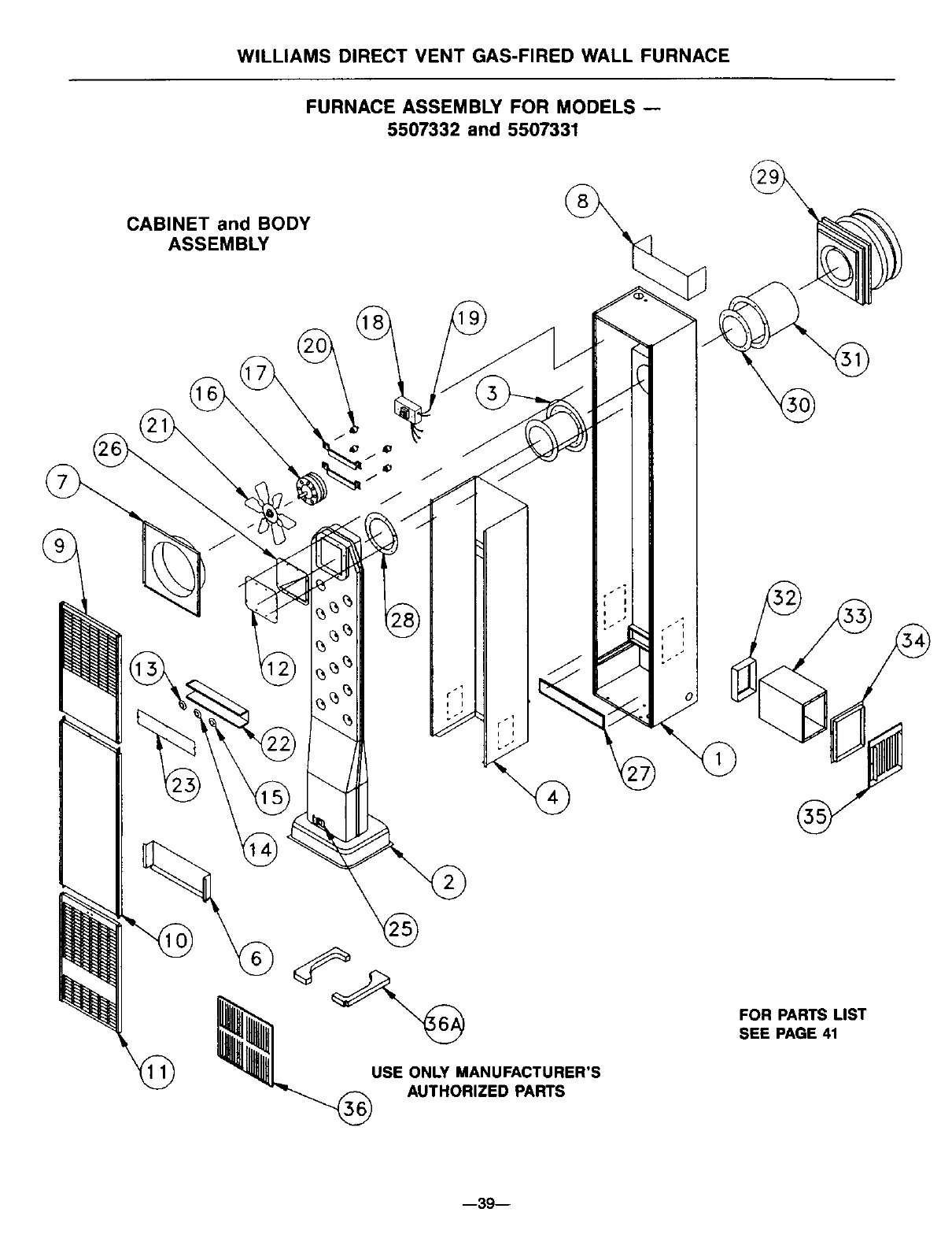
WILLIAMS DIRECT VENT GAS-FIRED WALL FURNACE
FURNACE ASSEMBLY FOR MODELS --
5507332 and 5507331
CABINET and BODY
ASSEMBLY
I
USE ONLY MANUFACTURER'S
AUTHORIZED PARTS
FOR PARTS LIST
SEE PAGE 41
--39--
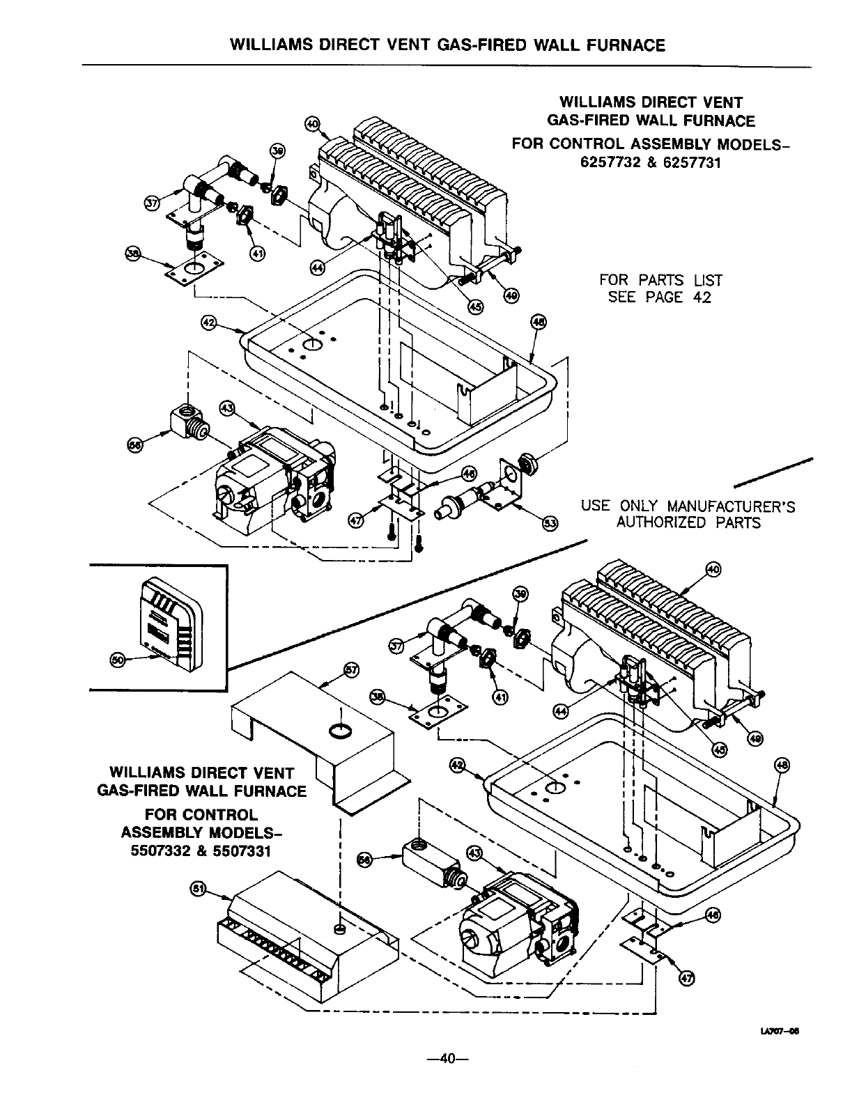
WILLIAMS DIRECT VENT GAS-FIRED WALL FURNACE
WILLIAMS DIRECT VENT
GAS-FIRED WALL FURNACE
FOR CONTROL ASSEMBLY MODELS-
6257732 & 6257731
FOR PARTS LIST
SEE PAGE 42
USE ONLY MANUFACTURER'S
"_ AUTHORIZED PARTS
WILLIAMS DIRECT VENT
GAS-FIRED WALL FURNACE
FOR CONTROL
ASSEMBLY MODELS-
5507332 & 5507331
s I
.... J
LAI07--_
40--
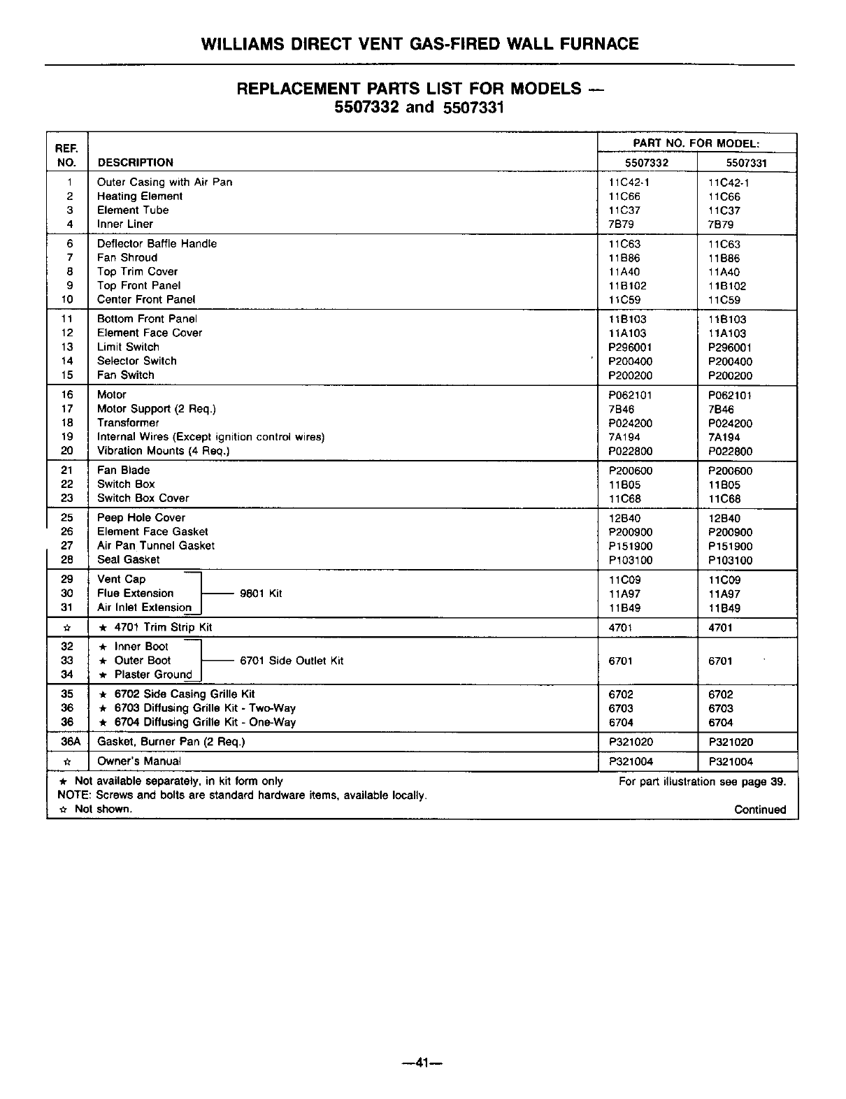
WILLIAMS DIRECT VENT GAS-FIRED WALL FURNACE
REPLACEMENT PANTS LIST FOR MODELS --
5507332 and 5507331
REF.
NO.
1
2
3
4
6
7
8
9
10
11
12
13
14
15
16
17
18
19
20
21
22
23
25
26
27
28
29
30
31
32
33
34
35
36
36
36A
DESCRIPTION
Outer Casing with Air Pan
Heating Element
Element Tube
Inner Liner
Deflector Baffle Handle
Fan Shroud
Top Trim Cover
Top Front Panel
Center Front Panel
Bottom Front Panel
Element Face Cover
Limit Switch
Selector Switch
Fan Switch
Motor
Motor Support (2 Req.)
Transformer
Internal Wires (Except ignition control wires)
Vibration Mounts (4 Req,)
Fan Blade
Switch Box
Switch Box Cover
Peep Hole Cover
Element Face Gasket
Air Pan Tunnel Gasket
Seal Gasket
Vent Cap
Flue Extension -- 9801 Kit
Air Inlet Extension
*4701 Trim Strip Kit
_r Inner Boot
* Outer Boot
* Plaster Ground
6702 Side Casing Grille Kit
6703 Diffusing Grille Kit -Two-Way
6704 Diffusing Grille Kit -One-Way
Gasket, Burner Pan (2 Req.)
-- 6701 Side Outlet Kit
PART NO. FOR MODEL:
5507332
11C42-1
11C66
11C37
7B79
11C63
11B86
11A40
11B102
11C59
ttB103
11A103
P296001
P200400
P200200
P062101
7B46
P024200
7A194
P022800
P200600
11B05
11C68
12B40
P200900
P151900
P103106
11C09
11A97
11B49
4701
6701
5507331
11C42-1
11C66
11C37
7B79
11C63
11B86
11A40
11Bt02
11C59
11B103
11A103
P296001
P2OO400
P200200
P062101
7B46
P024200
7A194
P022800
P200600
11B05
11C68
12B40
P2O090O
P151900
P103100
11C09
11A97
11B49
4701
6701
6702 6702
6703 6703
6704 6704
P321020 P321020
Owner's Manual P321004 P321004
* Not available separately, in kit form only For part illustration see page 39.
NOTE: Screws and bolts are standard hardware items, available locally.
_r Not shown. Continued
--41--
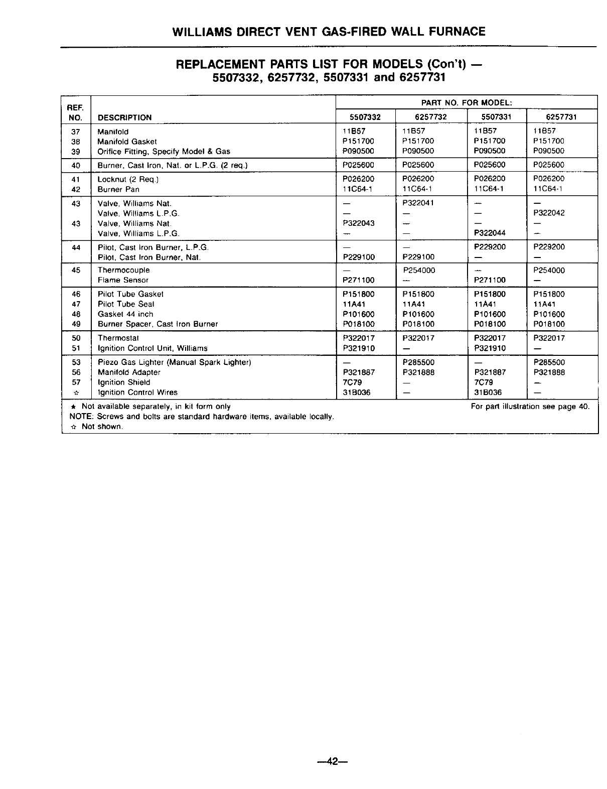
WILLIAMS DIRECT VENT GAS-FIRED WALL FURNACE
REPLACEMENT PARTS LIST FOR MODELS (Con't) --
5507332, 6257732, 5507331 and 6257731
RER
NO, DESCRIPTION
37
38
39
40
41
42
43
43 P322043
44
P229100
45
P271100
46 P151800
47 11A41
48 P101600
49 P018100
50 P322017
51 P321910
53
56 P321887
57 7C79
31B036
,* Not available separately, in kit form only
NOTE: Screws and bolts are standard hardware items, available locally.
_r Not shown.
Manifold
Manifold Gasket
Orifice Fitting, Specify Model &Gas
Burner, Cast Iron, Nat. or L.P.G, (2 req.)
Locknut (2 Req)
Burner Pan
Valve, Williams Nat.
Valve, Williams L.P.G.
Valve, Williams Nat.
Valve, Williams L.P.G
Pilot, Cast Iron Burner, L.P.G.
Pilot, Cast Iron Burner, Nat
Thermocouple
Flame Sensor
Pilot Tube Gasket
Pilot Tube Seal
Gasket 44 inch
Burner Spacer, Cast Iron Burner
Thermostat
Ignition Control Unit, Williams
Piezo Gas Lighter (Manual Spark Lighter)
Manifold Adapter
Ignition Shield
Ignition Control Wires
5507332
11B57
P151700
P090500
P025600
P026200
11C64-1
PART NO. FOR MODEL:
6257732 5507331
11B57 t1B57
P151700 P151700
P090500 P090500
P025600 P025600
P026200 P026200
11C64-1 11C64-1
P322041
P229100
P254000
P151800
11A41
P101600
P018100
P322017
P285500
P321688
6257731
11B57
P151700
P090500
P025600
P026200
11C64-1
-- P322042
P322044
P229200 P229200
-- P254000
P271100
P151800 P151800
11A41 11A41
P101600 P101600
P018100 P018100
P322017 P322017
P321910
-- P285500
P321887 P321866
7C79
31B036
For pad illustr_ion see page 40.
--42--
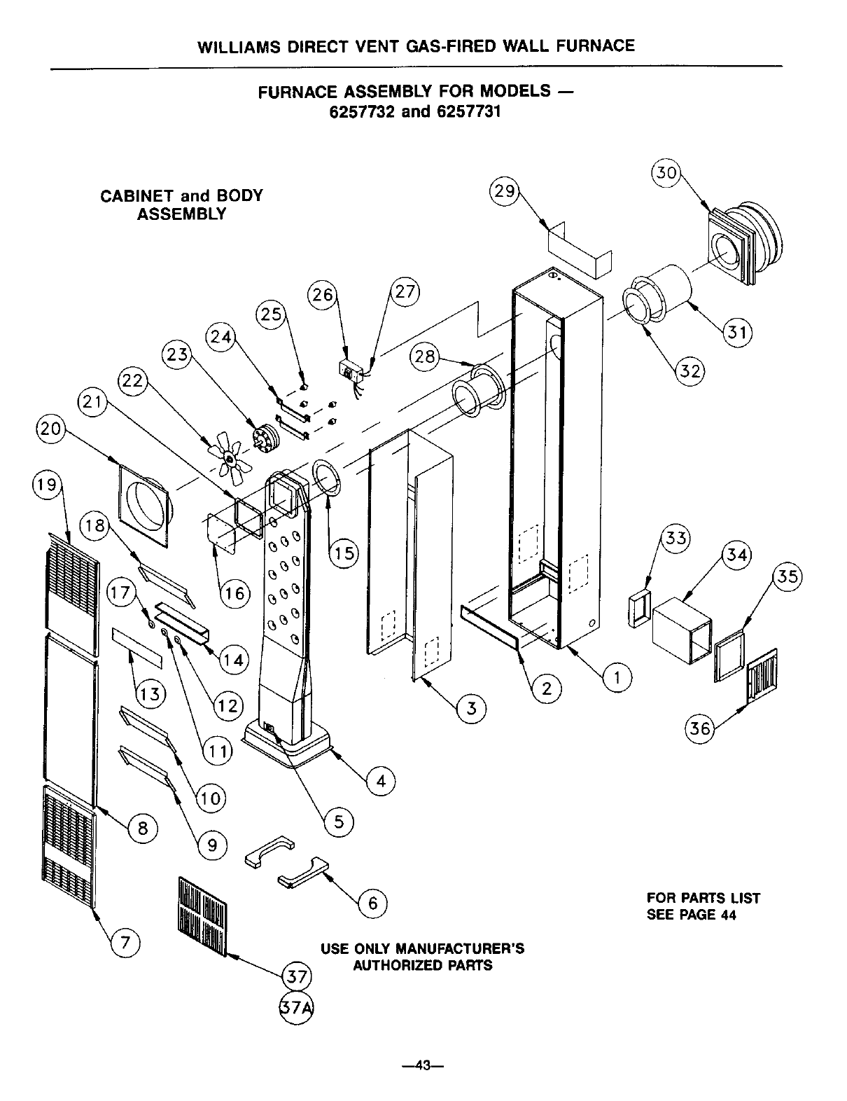
WILLIAMS DIRECT VENT GAS-FIRED WALL FURNACE
FURNACE ASSEMBLY FOR MODELS --
6257732 and 6257731
CABINET and BODY
ASSEMBLY
USE ONLY MANUFACTURER'S
AUTHORIZED PARTS
FOR PARTS LIST
SEE PAGE 44
--43--
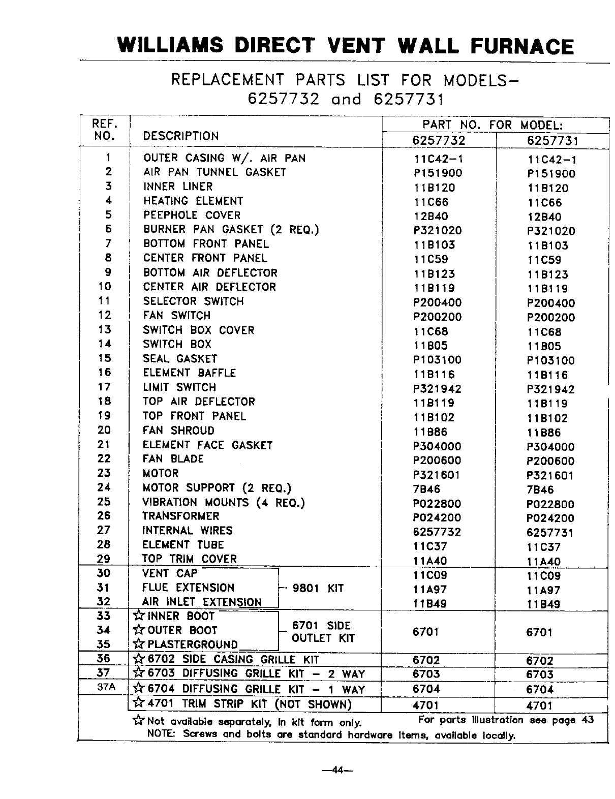
WILLIAMS DIRECT VENT WALL FURNACE
REF.
NO.
1
2
3
4
5
6
7
8
9
10
11
12
13
14
15
16
17
18
19
20
21
22
23
24
25
26
27
28
29
3O
31
32
53
34
35
56
37
37A
REPLACEMENT PARTS LIST FOR MODELS-
6257732 and 6257731
DESCRIPTION
OUTER CASING W/. AIR PAN
AIR PAN TUNNEL GASKET
INNER LINER
HEATING ELEMENT
PEEPHOLE COVER
BURNER PAN GASKET (2 RE(;}.)
BOTTOM FRONT PANEL
CENTER FRONT PANEL
BOTTOM AIR DEFLECTOR
PART
6257732
11C42-1
P151900
11B120
11C66
12B40
P521020
11B103
11C59
11B125
CENTER AIR DEFLECTOR
SELECTOR SWITCH
FAN SWITCH
SWITCH BOX COVER
SWITCH BOX
SEAL GASKET
ELEMENT BAFFLE
LIMIT SWITCH
TOP AIR DEFLECTOR
TOP FRONT PANEL
FAN SHROUD
11Bl19
P20O40O
P200200
11C68
11B05
P105100
11Bl16
P521942
11Bl19
11B102
11B86
NO. FOR MODEL:
6257731
11C42-1
P151900
11B120
11C66
12B40
P321020
11B105
11C59
11B125
11Bl19
P200400
P200200
11C68
11B05
P103100
11Bl16
P521942
11Bl19
11B102
11B86
ELEMENT FACE GASKET
FAN BLADE
MOTOR
MOTOR SUPPORT (2 REQ.)
VIBRATION MOUNTS (4 REQ.)
TRANSFORMER
INTERNAL WIRES
ELEMENT TUBE
TOP TRIM COVER
VENT CAP
FLUE EXTENSION - 9801 KIT
AIR INLET EXTENSION
_" INNER BOOT
_'OUTER BOOT 6701 SIDE
PLASTERGROUND OUTLET KIT
"_6702 SIDE CASING GRILLE KIT
_'6705 DIFFUSING GRILLE KIT - 2 WAY
_'6704 DIFFUSING GRILLE KIT - 1 WAY
_'4701 TRIM STRIP KIT (NOT SHOWN)
P304000
P200600
P321601
7B46
P022800
P024200
6257752
11C57
11A40
11C09
11A97
11B49
6701
6702
6705
6704
4701
_" Not available separately, in kit form only. For parts Illustration
NOTE: Screws and bolts are standard hardware Items, available locally.
P504000
P200600
P321601
7B46
P022800
P024200
6257751
11C37
11A40
11C09
11A97
11B49
6701
6702
6703
6704
4701
see page 45
--44--
Service Record
DATE MAINTENANCE PERFORMED COMPONENTS REQUIRED
.--45 m

-- Notes --
--46--

-- Notes --
owners
manual
SERVICE
MODEL NOS.
4007332
4007732
5507332
6257732
4007331
4007731
5507331
6257731
Service Hints
If your furnace fails to work right, you may avoid inconvenience and the cost
of a service call by checking the following points before you call for service.
FOR YOUR SAFETY FOR YOUR SAFETY
Do not store or use gasoline If you smell gas:
or other flammable vapors and 1. Open windows.
2. Don't touch electrical.
liquids in the vicinity of this or any 3. Extinguish any open flame.
other appliance. 4. Immediately call your gas
supplier.
POSSIBLE CAUSE WHAT TO DO
If fan motor is noisy --
Housing rattling.
Fan dirty.
Fan blade bent.
Motor bearings need oiling.
Tighten screws.
Clean fan blade.
Replace fan blade.
Oil motor.
If fan does not run -
Fuse blown or tripped circuit
breaker.
Motor bearings need oiling.
Replace fuse or reset breaker.
Oil motor.
If burner is noisy --
Pilot observation door loose or
missing. (peep hole cover)
Tighten wingnut or replace
door.
If your furnace is not heating or not giving enough heat --
Replace fuse or reset breaker,Fuse blown or tripped circuit
breaker.
Thermostat is not set correctly.
Air flow restricted.
Reset thermostat to desired
setting.
Check that doors, drapes or
furniture are not blocking
furnace louvers.
If your furnace short cycles --
Thermostat anticipator not set
correctly.
Set anticipator (See Page 11).
If your furnace pops and cracks --
Heat exchanger expansion and Normal condition, especially
contraction, with newer furnaces.
See troubleshooting section for more detailed information.
Illustrations are representative only.
Specifications are subject to change without notice.
How to Order Repair Parts
When ordering repair parts, always give the following All parts listed herein may be ordered from your equip-
information: ment supplier.
1. MODELNUMBER The Model Number of your Williams wall furnace will be
2. MFG.DATECODE found on the rating plate near gas valve, inside control
3. PART NUMBER
4. PART DESCRIPTION compartment.
WILLIAMS FURNACE COMPANY
225 Acacia Street
Colton, CA 92324 USA
(909) 825-0993
MANUFACTURED
IN THE U.S.A.
Established 1916
FAX: (909) 824-8009
©1998 The Williams Furnace Company Printed in U.S.A. Rev. 12/98 P321004
