WINIA Electronics DLN-17D3 17" LCD Monitor User Manual
Dongbu Daewoo Electronics Corporation 17" LCD Monitor Users Manual
UserManual.wiki
>
WINIA Electronics
>
DLN 17D3 User Manual
Users Manual
Navigation menu
Upload a User Manual
Namespaces
Wiki Guide
HTML
PDF
Info
Views
User Manual
Discussion / Help
Navigation
![FunctionalOverview Remote Controller [ ] : Teletext function 10123456789PICTUREMODE SOUNDMODEDISPLAY MTSTV AVCOMPONENTPCPOWERMUTEVOL VOLCHCHPREV. CHCAPTIONSLEEPTV/CABLEADD/DELASPECTMENU0100MUTE MUTEMENUCH UPLEFT(VOLUME DOWN) RIGHT(VOLUME UP)CH DOWNPREV. CHASPECTSLEEPDISPLAYNUMBER(PAGE)PICTURE MODESOUND MODEADD/DELAV/CABLE](https://usermanual.wiki/WINIA-Electronics/DLN-17D3/User-Guide-489582-Page-10.png)
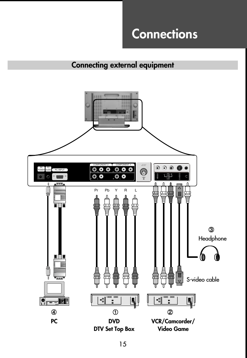
![Connections16You can enjoy picture and sound by connecting VCR, DVD player (or DTV Set-Top Box) andPC to the terminals located on the back of TV set. Before connecting an external device, turn theTV set off to avoid any possible damage.DVD or DTV Set-Top Box input terminal [COMPONENT IN]These jacks have Y/Pb(Cb)/Pr(Cr) inputs and AUDIO inputs.These jacks are used to connect a DVD player, DTV Set-Top Box. (Available input mode :480i, 480p, 720p, 1080i)External AV devices input terminal [AV IN]These jacks have VIDEO/AUDIO/S-VIDEO inputs. Connect them to VCR, Camcorder orVideo game with RCA or S-VIDEO cable.* If your AV device has both VIDEO OUT terminal and S-VIDEO OUT terminal, S-VIDEOconnection is recommended for better picture quality.• VIDEO and S-VIDEO in AV IN share the same jack with AUDIO input. Thus, they can’t beused at the same time.• Whenever you connect external equipment system to TV, make sure that all elements areswitched off. Refer to the documentation supplied with your equipment for detailedconnection instructions and associated safety precautions.Headphone JackInsert the headphone plug (3.5mmØ) into this jack. The sound from the speaker will beautomatically cut off. You can control the headphone sound with Volume Up/Down ( )buttons.* Headphones are not included in the supplied accessories.PC InConnect the D-sub 15 pin cable and the audio cable with personal computer.* See page 24 for more information of PC mode.](https://usermanual.wiki/WINIA-Electronics/DLN-17D3/User-Guide-489582-Page-16.png)
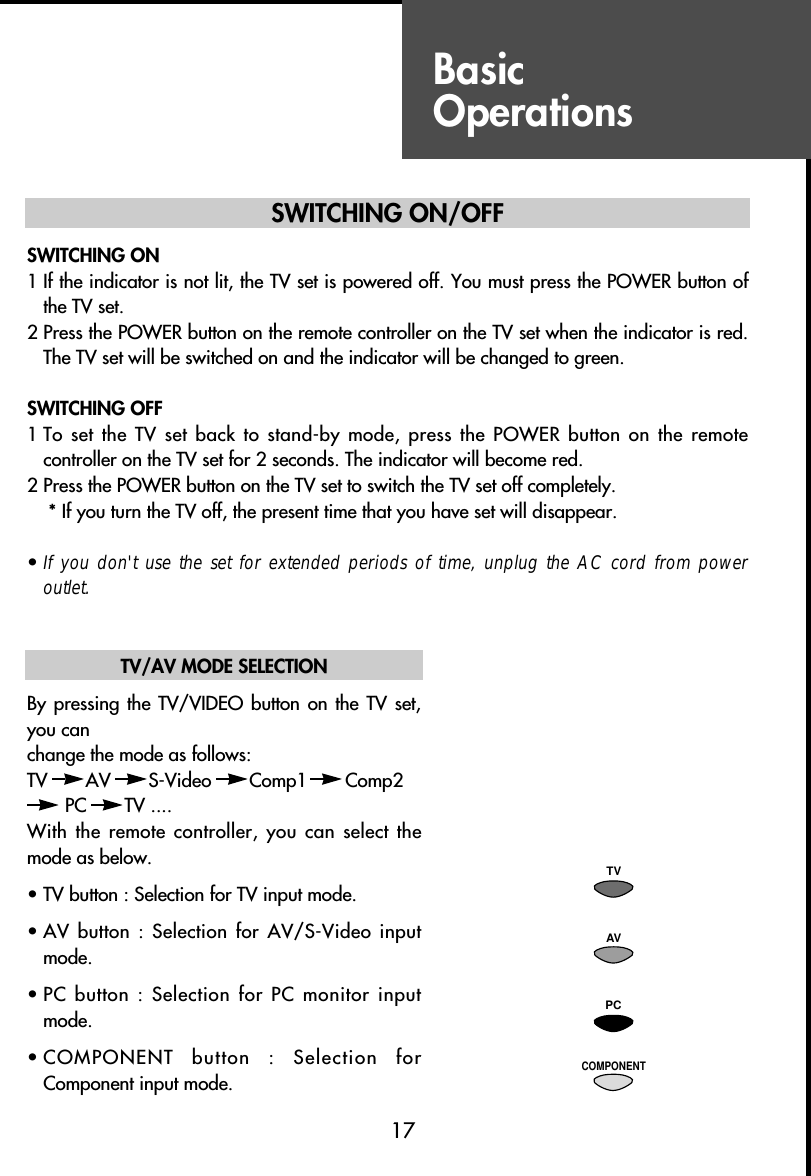
![BasicOperations18VOLUME CONTROLAdjust the volume with VOL ( ) buttons.TO MUTE THE SOUNDPress the MUTE button on the remote controller tocut the sound off. By pressing either the MUTEbutton or VOL ( ) buttons, you can get soundback.CHANNEL SELECTIONThe TV set has 68 channels [AIR02 ~ AIR69] inAIR mode and 125 channels [CATV01 ~CATV125] in CATV mode. (Refer to next page foreach selection.)DIRECT SELECTIONThe numeric buttons are used for direct channelselection. To select two-digit channels, press thesecond number button within 2 seconds after thefirst number.To select 3-digit channels, press ‘+100’ buttonbefore pressing the rest of number buttons inorder.• Channel number in green : Memorizedchannels by automatic search or addedchannels by user.Channel number in white : Skipped channels byautomatic search or deleted channels by user.UP/DOWN SELECTIONYou can also select a memorized channel bypressing the CH ( ) buttons.VOL VOLMUTE123457890100CHCH](https://usermanual.wiki/WINIA-Electronics/DLN-17D3/User-Guide-489582-Page-18.png)