WIZNET WIZ6000 Serial to Wireless LAN Device Server User Manual WIZ6000 V0 9
WIZNET Co., LTD. Serial to Wireless LAN Device Server WIZ6000 V0 9
WIZNET >
User Manual
WIZ6000 User’s Manual (WIZnet, Inc.)
-
1 -
WIZ6000 User’s Manual
(Version 0.9)
©2009 WIZnet Co., Inc. All Rights Reserved.
☞ For more information, visit our website at http://www.wiznet.co.kr

WIZ6000 User’s Manual (WIZnet, Inc.)
- 2 -
Document Revision History
Date Revision Changes
2009-09-09 V0.9 Beta Release

WIZ6000 User’s Manual (WIZnet, Inc.)
- 3 -
Certification Information
CE for Class B ITE
INFORMATION TO THE USER
Hereby, WIZnet. Declares that this WIZ6000 is in compliance with the essential requirements
and other relevant provisions of directive 1999/5/EC.
WARNING: This is a class B product. In a domestic environment this product may cause radio
interference in which case the user may be required to take adequate measures.
FCC for Class B ITE
INFORMATION TO THE USER
This equipment has been tested and found to comply with the limits for a Class B digital device,
pursuant to part 15 of the FCC Rules. These limits are designed to provide reasonable
protection against harmful interference in a residential installation. This equipment generates,
uses and can radiate radio frequency energy and, if not installed and used in accordance with
the instructions, may cause harmful interference to radio communications. However, there is no
Guarantee that interference will not occur in a particular installation. If this equipment does
cause harmful interference to radio or television reception, which can be determined by turning
the equipment off and on, the user is encouraged to try to correct the interference by one more
of the following measures:
- Reorient or relocate the receiving antenna.
- Increase the separation between the equipment and receiver.
- Connect the equipment into an outlet on a circuit different from that to which the
receiver is connected.
- Consult the dealer or an experienced radio/TV technician for help.
WARNING: This equipment may generate or use radio frequency energy. Changes or
modifications to this equipment may cause harmful interference unless the modifications are
expressly approved in the instruction manual. The user could lose the authority to operate this
equipment if an unauthorized change or modification is made.
KCC for Class B ITE
INFORMATION TO THE USER
This equipment has been tested for a Class B digital device.
- Trade Name or Applicant : WIZnet, Inc.
- Equipment Name : Serial to Wireless LAN Device Server
- Basic Model Number : WIZ6000
- Manufacturer / Country of Origin : WIZnet, Inc. / KOREA
- Certification Number : WWW-WIZ6000-S2W(B)
WARNING: This equipment may generate or use radio frequency energy. Changes or
modifications to this equipment may cause harmful interference.
Near-Body Operation
To maintain compli ance with FCC RF exposure re quirements, maint ain a 20Cm, s eparation
distance between the u ser's body a nd the pho ne, including the antenna, whether extended or
retracted.

WIZ6000 User’s Manual (WIZnet, Inc.)
- 4 -
WIZnet’s Online Technical Support
If you have any questions about our products, please visit our website and submit your
questions on the Q&A Board. We will reply your questions as soon as possible
COPYRIGHT NOTICE
Copyright 2009 WIZnet, Inc. All Rights Reserved.
Technical Support: support@wiznet.co.kr
Sales & Distribution: sales@wiznet.co.kr
For more information, visit our website at http://www.wiznet.co.kr
C
CL
LI
IC
CK
K

WIZ6000 User’s Manual (WIZnet, Inc.)
- 5 -
Contents
1. Introduction ........................................................................................................................ 1
1.1 Products Contents ............................................................................................. 2
1.2 Product Specification ......................................................................................... 3
1.2.1 WIZ6000 Device Server Interface ..................................................................... 5
2. Getting Started ................................................................................................................... 6
2.1 Hardware Installation ................................................................................................. 6
2.2 Configuration ............................................................................................................. 6
2.2.1 Connecting the Web page of WIZ6000 .............................................................. 6
2.2.2 Checking Status ............................................................................................... 7
2.2.3 Network Setting ............................................................................................... 9
2.2.4 Wireless Setting ............................................................................................. 10
2.2.4.1 Mode Selection .................................................................................... 10
2.2.4.2 IP Configuration in Each Mode .............................................................. 12
2.2.4.3 Access Point Setup............................................................................... 14
2.2.4.4 Gateway Setup ..................................................................................... 19
2.2.4.5 Client Setup ......................................................................................... 23
2.2.5 Serial Setting ................................................................................................. 24
2.2.6 Security Setup ............................................................................................... 27
2.2.7 Others ........................................................................................................... 27
2.2.7.1 Password ............................................................................................. 27
2.2.7.2 Log ...................................................................................................... 27
2.2.7.3 Upgrade ............................................................................................ 28
2.2.7.4 Factory Default .................................................................................. 28
2.2.7.5 Reboot .............................................................................................. 29
3. Hardware Specification ..................................................................................................... 30
3.1 WIZ6000 Dimension ................................................................................................ 30
3.2 Connector Specification ........................................................................................... 31
3.2.1 RJ-45 Connector ............................................................................................ 31
3.2.2 RS-232C Connector ....................................................................................... 31
4. Demonstration and Test .................................................................................................... 32
5. Serial Configuration .......................................................................................................... 36
6. Warranty .......................................................................................................................... 44

WIZ6000 User’s Manual (WIZnet, Inc.)
- 6 -
Figures
FIGURE 1. WIZ6000 DEVICE SERVER INTERFACE ............................................................................. 5
FIGURE 2. CONNECTING TO THE WEB PAGE OF WIZ6000 .................................................................. 6
FIGURE 3. INPUT ID AND PASSWORD ................................................................................................. 7
FIGURE 4. SYSTEM DATA .................................................................................................................. 7
FIGURE 5. ACTIVE CLIENTS .............................................................................................................. 8
FIGURE 6. NETWORK SETTING ......................................................................................................... 9
FIGURE 7. ACTIVE DHCP CLIENT TABLE ......................................................................................... 10
FIGURE 8. OPERATION MODE ......................................................................................................... 10
FIGURE 9. CHANGING OPERATION MODE ........................................................................................ 11
FIGURE 10. ACCESS POINT MODE - 1 ............................................................................................. 12
FIGURE 11. ACCESS POINT MODE -2 .............................................................................................. 12
FIGURE 12. GATEWAY MODE .......................................................................................................... 13
FIGURE 13. CLIENT MODE .............................................................................................................. 13
FIGURE 14. AP MODE SETTINGS .................................................................................................... 14
FIGURE 15. WIRELESS SECURITY SETUP ........................................................................................ 15
FIGURE 16. WIRELESS ADVANCED SETTINGS .................................................................................. 17
FIGURE 17. WIRELESS ACCESS CONTROL ...................................................................................... 18
FIGURE 18. WDS SETTING ............................................................................................................ 19
FIGURE 19. GATEWAY SETUP ......................................................................................................... 20
FIGURE 20. WAN PORT CONFIGURATION ........................................................................................ 21
FIGURE 21. WAN ACCESS TYPE - PPPOE ...................................................................................... 22
FIGURE 22. CLIENT SETUP ............................................................................................................. 23
FIGURE 23. SITE SURVEY ............................................................................................................... 24
FIGURE 24. SERIAL TO ETHERNET CONFIGURATION ......................................................................... 24
FIGURE 25. PASSWORD SETUP ....................................................................................................... 27
FIGURE 26. SYSTEM LOG ............................................................................................................... 27
FIGURE 27. UPGRADE FIRMWARE ................................................................................................... 28
FIGURE 28. REBOOT SYSTEM ......................................................................................................... 29
FIGURE 29. WIZ6000 DIMENSIONS (UNIT : MM) ............................................................................... 30
FIGURE 30. RJ-45 PIN ASSIGNMENT .............................................................................................. 31
FIGURE 31. SERIAL TERMINAL PROGRAM CONFIGURATION ............................................................... 32
FIGURE 32. WIRELESS NETWORK CONNECTION .............................................................................. 33
FIGURE 33. NETWORK TERMINAL PROGRAM CONFIGURATION .......................................................... 33
FIGURE 34. RECEIVED DATA B Y NETWORK TERMINAL PROGRAM ...................................................... 34
FIGURE 35. SERIAL TO WIRELESS LAN 구성 .................................................................................. 34
FIGURE 36. DEVICE TERMINAL PROGRAM ....................................................................................... 35

WIZ6000 User’s Manual (WIZnet, Inc.)
- 7 -
Tables
TABLE 1. PRODUCTS CONTENTS. ...................................................................................................... 2
TABLE 2. PRODUCTS SPECIFICATION – WIRELESS ............................................................................. 3
TABLE 3. PRODUCTS SPECIFICATION - SOFTWARE ............................................................................. 3
TABLE 4. PRODUCTS SPECIFICATION - HARDWARE .......................................................................... 4
TABLE 5. SYSTEM DATA .................................................................................................................... 8
TABLE 6. AUTHENTICATION METHOD ............................................................................................... 16
TABLE 7. WEP CONFIGURATION ..................................................................................................... 16
TABLE 8. WIRELESS ADVANCED SETTINGS ...................................................................................... 18
TABLE 9. FACTORY DEFAULT VALUE ................................................................................................ 29
TABLE 10. RS-232 PIN ASSIGNMENT ............................................................................................. 31
TABLE 11. SERIAL CONFIGURATION FRAME FORMAT ......................................................................... 36
TABLE 12. SERIAL CONFIGURATION REPLY FRAME FORMAT .............................................................. 36
TABLE 13. SERIAL CONFIGURATION STX & ETX .............................................................................. 36
TABLE 14. SERIAL CONFIGURATION REPLY CODE ............................................................................ 37

WIZ6000 User’s Manual (WIZnet, Inc.) 1
1. Introduction
WIZ6000 is t he external g ate way mod ule which provides a b ridge for RS -232 or Ethernet to
IEEE802.11 b/g wirel ess communications. Device s with the interface of RS -232C serial or
Ethernet can established a wireless network which can enable remote monitoring, management
and controlling.
Main Features
Embedded 802.11b/g Wireless Networking
Access Point, Client, Gateway, Serial to WLAN mode Supported
Ethernet to Wireless Bridging
Strong Security with 64/128 bit WEP, WPA, WPA2(AES)
Support Ethernet port, Serial port, Reset Button
Ready to use serial to wireless application
Max 25Mbps Data Streaming
Compact design 90.5mm X 94.5mm X 22.7mm ( L x W x H )
RoHS Compliant
CE, FCC and KCC certificated
WIZ6000 User’s Manual (WIZnet, Inc.) 2
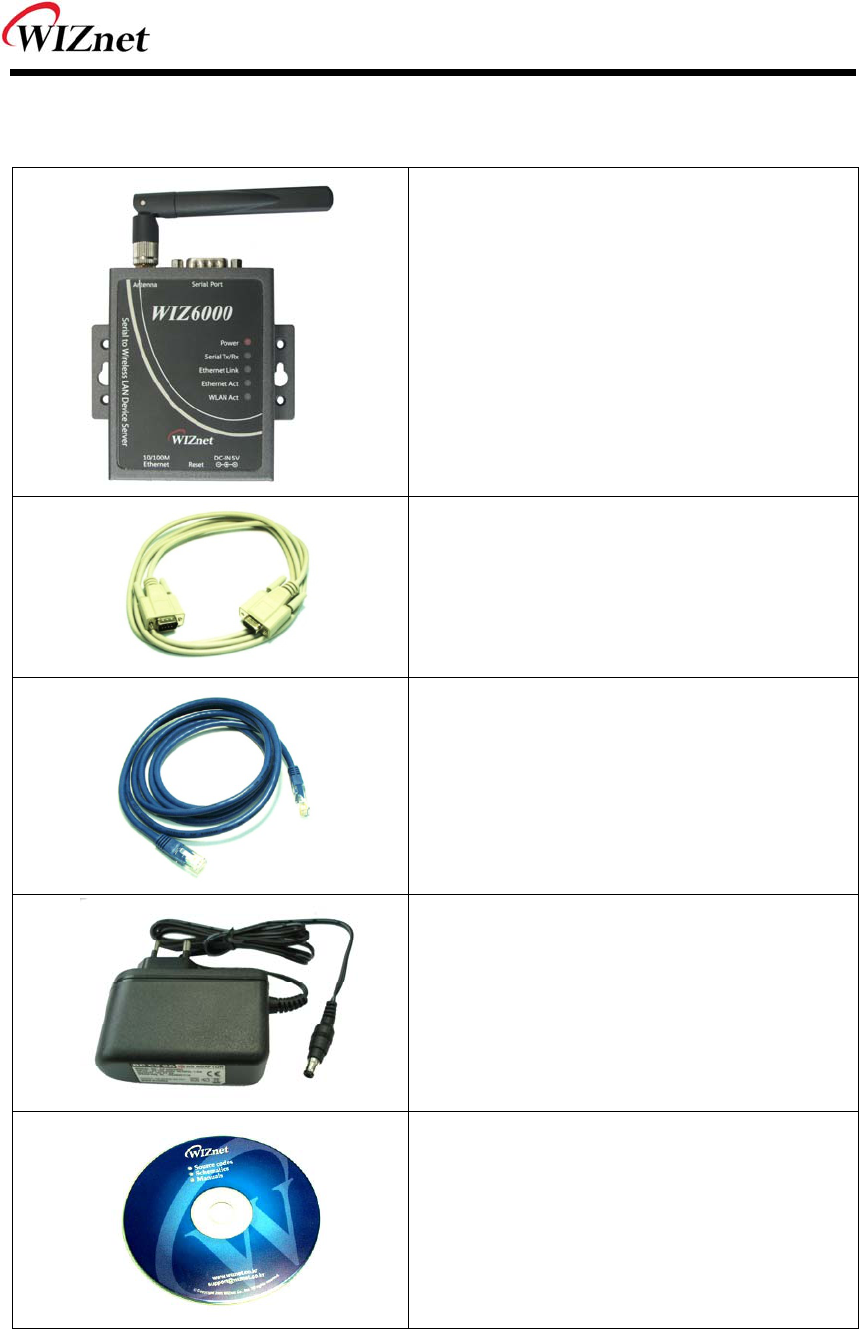
1.1 Products Contents
WIZ6000 Device Server
Included Dipole Antenna
(3.377dBi SMA Type)
Serial Cable
Network Cable
(Crossover Cable)
Power
(DC 5V / 2A Adaptor)
Data CD
(Manual, H/W & SW related Materials)
Table 1. Products Contents.

WIZ6000 User’s Manual (WIZnet, Inc.) 3
1.2 Product Specification
Wireless
ITEM Specification
Wireless Standard IEEE802.11b/g
Frequency Range 2.412~2.485GHz
Output Power
(Tolerance(+/-2dBm)
802.11b: 16dBm@11Mbps (Max 10mW / 1MHz)
802.11g: 14dBm@6~54Mbps (Max 10mW / 1MHz)
Receive Sensitivity
802.11b: -65dBm@11Mbps
802.11g: -76dBm@54Mbps
Data Rates 54Mbps-1Mbps
Modulation Type 11g: OFDM(64QAM, 16QAM, QPSK, BPSK)
11b: DSS(CCK, DQPSK, DBPSK)
Table 2. Products Specification – Wireless
Software
ITEM Specification
Operation Mode Access Point, Clinet, Gateway, Serial to Wireless LAN
Protocol
ARP, UDP , TCP, Telnet, ICMP , IGMP DHCP , PPPoE,
BOOTP, HTTP, TFTP
Security
WEP 64/128big
WPA/WPA2 PSK/AES/TKIP
802.1x(Radius)
Management HTTP, Telnet, Serial, UDP
Notification Event Logging
Table 3. Products Specification - Software

WIZ6000 User’s Manual (WIZnet, Inc.) 4
Hardware
ITEM Specification
Interface
Ethernet 1 Port, RS-232C 1 Port, DC 5V Power input
3.377dBi SMA type Dipole Antenna
Temperature
Operation: -5℃~55℃
Storage: -20℃~70℃
Humidity
Operation: 10% to 90%, Non-Condensing
Storage: 5% to 90%, Non-Condensing
Serial
(RS-232C)
Baud Rate : 230,400bps
Stop bits: 1
Parity: None, Odd, Even
Flow Control: XON / XOFF (Software),
CTS / RTS (Hardware), None
Power DC 5V input
Power Consumption Under 600mA ( 3.3V )
Dimension 90.5mm X 94.5mm X 22.7mm (Excluded antenna size)
Table 4. Products Specification - Hardware
WIZ6000 User’s Manual (WIZnet, Inc.) 5
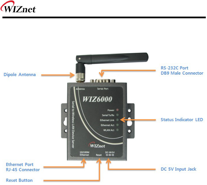
1.2.1 WIZ6000 Device Server Interface
Figure 1. WIZ6000 Device Server Interface

WIZ6000 User’s Manual (WIZnet, Inc.) 6
2. Getting Started
This manual describes all configurations in detail.
For the quick and easy installation, please refer to “ WIZ610wi Quick Installation Guide”.
2.1 Hardware Installation
STEP1: Connect the WIZ6000 to the HUB or PC by using a network cable.
STEP2: Connect the WIZ6000 to the serial device by using the RS-232C serial cable.
STEP3: Insert the power supply co nnector to the WIZ6000 by using the 5V / 2A
DC power adaptor.
STEP4: Configure the network parameters of WIZ6000 and your PC.
- The default IP address of WIZ6000 is “192.168.1.254”.
Your PC’s IP address should start with these three sets of numbers “192.168.1.XXX”.
- WIZ6000 and PC can be connected through wireless network.
Connect to WIZ6000 from PC by using default SSID “WIZ610wi”
2.2 Configuration
2.2.1 Connecting the Web page of WIZ6000
1) Open a web browser on your PC and input “192.168.1.254”, the default IP address of
WIZ6000.
Figure 2. Connecting to the Web page of WIZ6000
2) A pop up will request you to input your User ID and Password.
Default User ID : admin, Password : admin
WIZ6000 User’s Manual (WIZnet, Inc.) 7
Figure 3. Input ID and Password
2.2.2 Checking Status
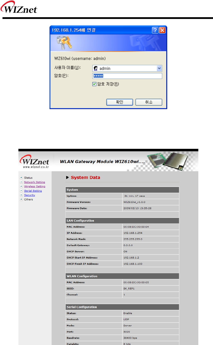
1) System Data
Figure 4. System Data
WIZ6000 User’s Manual (WIZnet, Inc.) 8
ITEM Description
Firmware Version The firmware version of WIZ6000 is displayed
Firmware Date The last date and time of firmware upgrade
MAC Address(LAN) The MAC Address of WIZ6000 for Ethernet communication.
IP Address The IP address of WIZ6000.
Network Mask The Network Mask of WIZ6000.
Default Gateway The Gateway of WIZ6000.
DHCP Server Shows the DHCP server function is activated or not.
DHCP Start IP Address Shows the first IP address to be assigned from DHCP server.
DHCP Finished IP Address Shows the last IP address to be assigned from DHCP server.
MAC Address(WLAN) The MAC Address for wireless communication.
SSID The SSID of WIZ6000.
Channel The wireless channel of WIZ6000.
Table 5. System Data
Notice
WIZ6000 supports the MAC address for both Ethernet and Wireless interface.
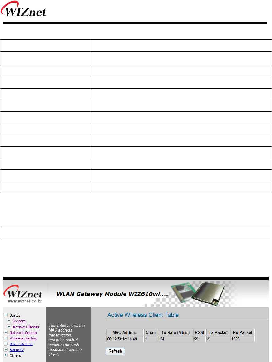
2) Active Client
Figure 5. Active Clients
In this p age, the information of client s con necting to WIZ610wi is displ ayed. If you click
“Refresh” button, the client list and information are updated.
WIZ6000 User’s Manual (WIZnet, Inc.) 9
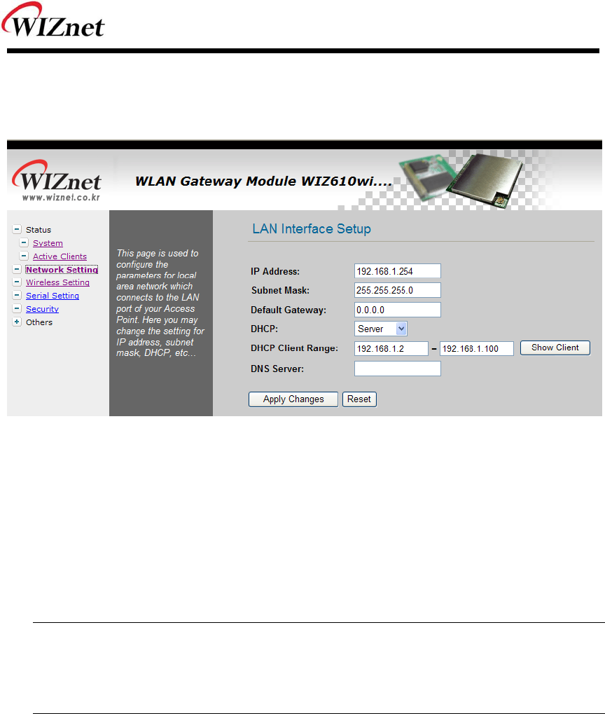
2.2.3 Network Setting
You can configure network parameters of WIZ6000
Figure 6. Network Setting
IP Address: The default IP Address is set as “192.168.1.254”.
Subnet Mask: The default Subnet Mask is set as “255.255.255.0”.
Default Gateway: The default Gateway is set as “0.0.0.0”.
DHCP: If you want to activate the DHCP Server function, select the “Server”.
If not, select “Disable”.
Notice
When the WI Z6000’s IP address is m anaged by another DHCP server in the upper layer,
the DHCP function in your wireless module will be disabled. All your clients connecting to
your WIZ6000 can not recognize your module as a DHCP server.
DHCP Client Range: When WIZ6000 operates as the DHCP Server, the IP address range
must be assi gned in ord er for the client s to conn ect. If the DHCP
server function is disabled, this DHCP Client Range is not activated.
Show Client: If you click the “Show Client” button, a window is popped up to show a list of
clients.
Apply Changes: By clicking this button, the modified values are applied. After changing,
the page is refreshed to re-connected to the new IP address.
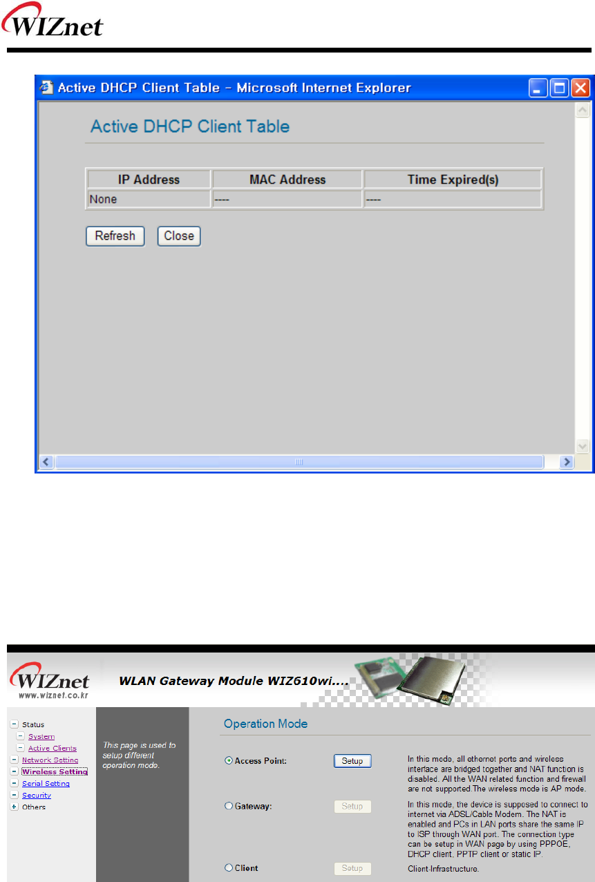
WIZ6000 User’s Manual (WIZnet, Inc.) 10
Figure 7. Active DHCP Client Table
2.2.4 Wireless Setting
2.2.4.1 Mode Selection
You can select one of Access Point, Gateway and Client for the wireless connection mode.
Figure 8. Operation Mode
Access Point is the default mode. If you select Gateway or Client and click the “Setup” button,
the progress bar will be shown.

WIZ6000 User’s Manual (WIZnet, Inc.) 11
Figure 9. Changing Operation Mode
1)Access Point Mode
In this mode, all Ethernet port s and wireless interface are bridged together and NAT function is
disabled. All the WAN related function and firewall are not supported.
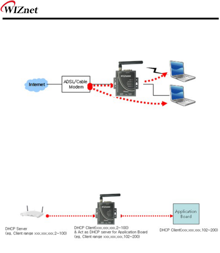
2)Gateway Mode
In this m ode, your d evice can conn ect to the inte rnet via ADS L/Cable Mo dem. The NAT is
enabled and PCs in LAN ports share the same IP to ISP through WAN port. WAN connection
type can be setup in WAN page by using PPPOE, DHCP client, PPTP client or static IP.
3)Client Mode
In this mode, your device act as a clie nt. If you con figure PC or application device a s DHCP
client, Access Point will be the DCHP Server and WIZ610wi doesn’t act as DHCP Server.
WIZ6000 User’s Manual (WIZnet, Inc.) 12
2.2.4.2 IP Configuration in Each Mode
1) Access Point Mode
Figure 10. Access Point Mode - 1
- The IP address assigned to WIZ6000 is for administration and web configuration.
- Even though the WIZ6000 is configured as DHCP Server, the PC will acquire IP address from
IP Sharing device or ADSL/Cable Modem.
Figure 11. Access Point Mode -2
- If there is not IP Sharing Device or ADSL/Cable modem, WIZ6000 will assign the IP addresses
which is in DHCP IP range to PCs through wired or wireless network.
WIZ6000 User’s Manual (WIZnet, Inc.) 13
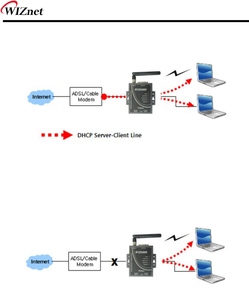
2) Gateway Mode
Figure 12. Gateway Mode
- WIZ6000 operates as DHCP Server for the wireless communication.
- WIZ6000 operates as Static/DHCP/Client/PPPoE for the wired (Ethernet) communication.
3) Client Mode
Figure 13. Client Mode
- WIZ6000 can be set IP as Static or DHCP client at ‘Client Setup>WAN Port Setup’.
And also WIZ6000 can b e act DHCP Server simultaneously by assigning a dding 100 of fi rst
DHCP server . For exam ple, if DHCP server ’s cl ient r ange is XXX.XXX.XXX.2~100, then
WIZ6000’s assigning DHCP Client IP address to application board is XXX.XXX.XXX.102~200.
WIZ6000 User’s Manual (WIZnet, Inc.) 14
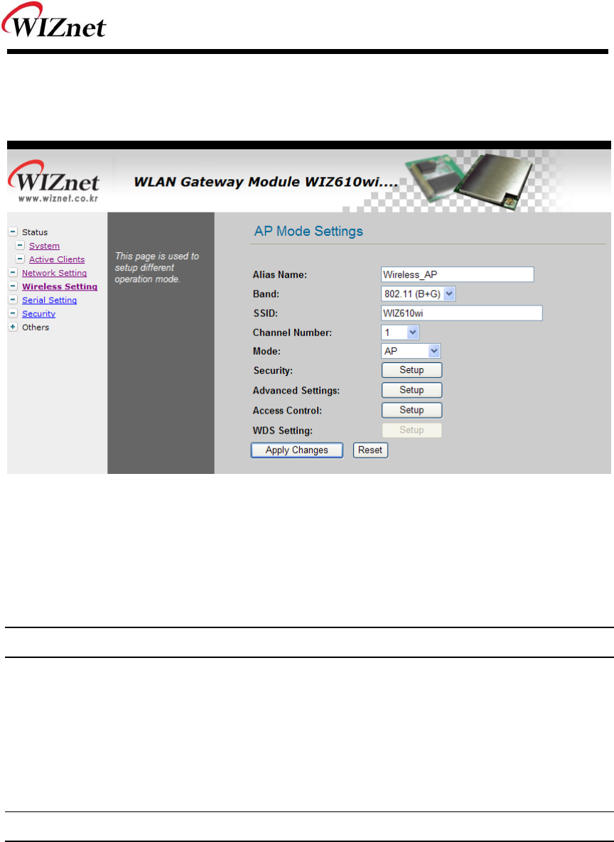
2.2.4.3 Access Point Setup
After selecting the AP mode and please click “Setup” button, the page below is shown.
Figure 14. AP Mode Settings
Alias Name : Input the name for WIZ6000.
Band : Select communication protocol of WIZ6000.
Notice
802.11g protocol is compatible with 802.11b.
SSID: Input SSID for wireless communication.
All devices o n the same wireless net work should have same S SID. The SSID ca n have max
32bytes characters composed of alphabets and numbers.
Notice
SSID field is case-sensitive.
Channel Number : Select the channel frequency which you will use for wireless
communication. If you select Auto, the connection is automatically
processed to the channel assigned by AP.
When AP is booted, it investigates wireless channel environment and
selects the lowest using channel.
And you can select a channel in the range of 1~13 manually.
WIZ6000 User’s Manual (WIZnet, Inc.) 15
Mode : Select mode
- AP : IF AP is selected, WIZ6000 operates as Access Point.
- WDS Repeater : WDS (Wireless Distribution System) that can be used for the
communication between WIZ6000 and WIZ6000.
When this mode is selected, AP function operates at the same time.
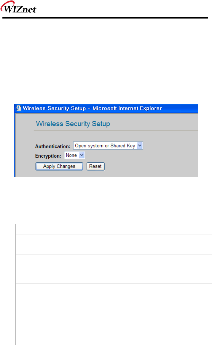
Security : Configure the security options for WIZ610wi. When you click “Setup” button, below
page appears.
Figure 15. Wireless Security Setup
Authentication
You can select an authentication method for the clients to connect to AP.
Field Description
Open System
or Shared Key
No authentication is imposed to the WIZ6000
When enabling WEP, the configuration is activated.
Open System
with 802.1x
The client authentication is performed by RADIUS server.
Configure the port number, IP address and Password of RADIS
server.
Shared Key WEB function is activated. Input the Key value.
WPA RADIUS WPA: Wi-Fi Protected Access
WPA is based on TKIP(Temporal Key Integrity Protocol) IEEE802.11i
standard which complements WEP(Wired Equivalent Privacy). WPA
is the upgraded authentication methods by applying 802.1x and EAP
(Extensible Authentication Protocol).

WIZ6000 User’s Manual (WIZnet, Inc.) 16
WPA PSK WPA Pre-Shared-Key is the authentication method using Pre-Shared
Key. Configure PSK format and input value for PSK.
WPA2 RADIUS WPA2 is using AES(Advanced Encryption Shared) algorithm. AES is
more strengthened encryption method rather than RC4 which is used
for WEP or WPA. WPA2 RADIUS performs AES encryption and
RADIUS server authentication. If WIZ610wi uses WPA2, it can be
compatible with devices using WPA1.
WPA2 PSK WPA2-PSK uses Advanced Encryption Standard(AES) for encryption
Keys together with WPA PSK method.
Table 6. Authentication Method
Encryption
It configures authentication mode fo r se curity of wirele ss network. The re a re options of
WEP and None. If WEP is selected, the below items are activated for configuration.
ITEM Description
key Length
Configure the length of WEP Key.
Option : 64 or 128bit
Key Format Configure the format of WEP Key.
Option : ASCII(5 Characters) or Hex(10 Character)
Default Tx Key Max 4 Tx Key values can be configured. Select one of them.
Encryption
Key 1~4
Input the key value.
Table 7. WEP Configuration
WIZ6000 User’s Manual (WIZnet, Inc.) 17
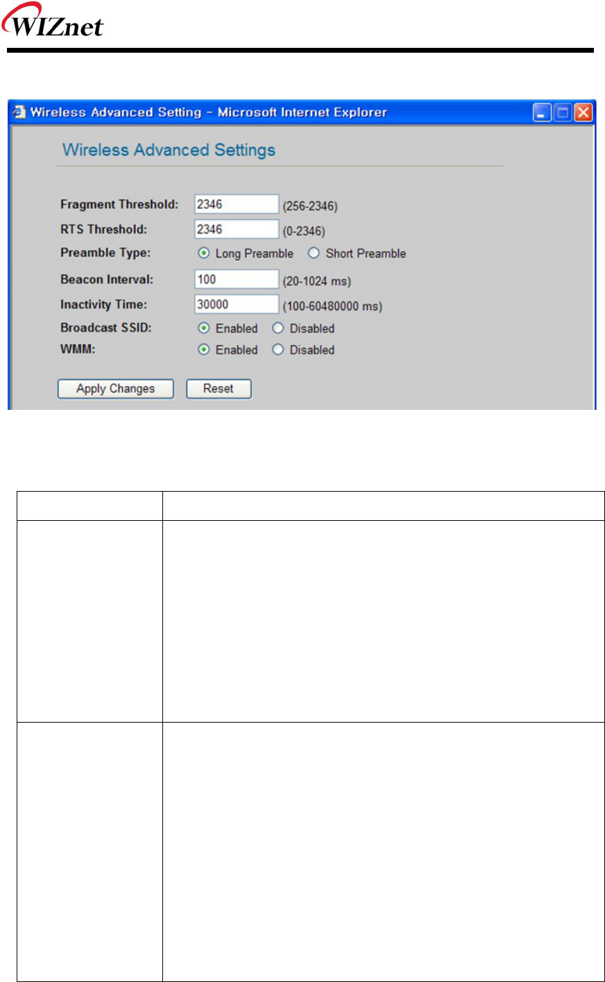
Advanced Settings : If you click the “Setup” button, below page is appeared.
Figure 16. Wireless Advanced Settings
Field Description
Fragment
Threshold
This value specifies the maximum size for a packet before data is
fragmented into multiple packets. If you experience a high packet
error rate, you may slightly increase the Fragmentation Threshold.
Setting the Fragmentation Threshold too low may result in poor
network performance. Only minor reduction of the default value is
recommended. In most cases, it should remain as its default value of
2346.
RTS Threshold When you encounter inconsistent data flow, only minor reduction of
the default value, 2347, is recommended. If a network packet is
smaller than the preset RTS threshold size, the RTS/CTS
mechanism will not be enabled. The Router sends Request to Send
(RTS) frames to a particular receiving station and negotiates the
sending of a data frame. After receiving an RTS, the wireless station
responds with a Clear to Send (CTS) frame to acknowledge the right
to begin transmission. The RTS Threshold value should remain as its
default value of 2347.
WIZ6000 User’s Manual (WIZnet, Inc.) 18
Preamble Type
Beacon Interval The default value is 100. Enter a value between 1 and 65,535
milliseconds. The Beacon Interval value indicates the frequency
interval of the beacon. A beacon is a packet broadcast by the Router
to synchronize the wireless network.
Table 8. Wireless Advanced Settings
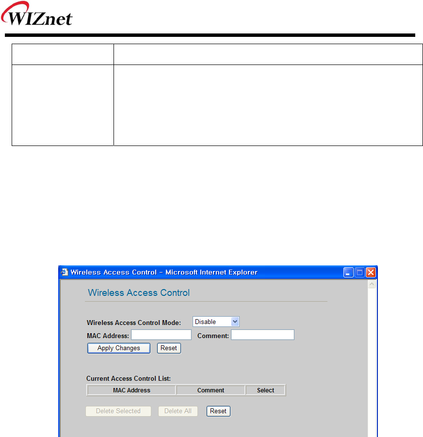
Access Control
By registering the MA C address of a client, WIZ6000 blocks or allows the client to acce ss. If
you click the “Setup” button, page below appears.
Figure 17. Wireless Access Control
Wireless Access Control Mode : This option allows you to enable or disable the “Wireless
Access Control Mode”. (Options: Disable / Allow Listed / Deny Listed)
Disable: Not use “Wireless Access Control Mode”.
Allow Listed: clients with their MAC registered in the Control List are permitted to access.
Deny Listed: clients with their MAC registered in the Control List are denied to access WIZ6000
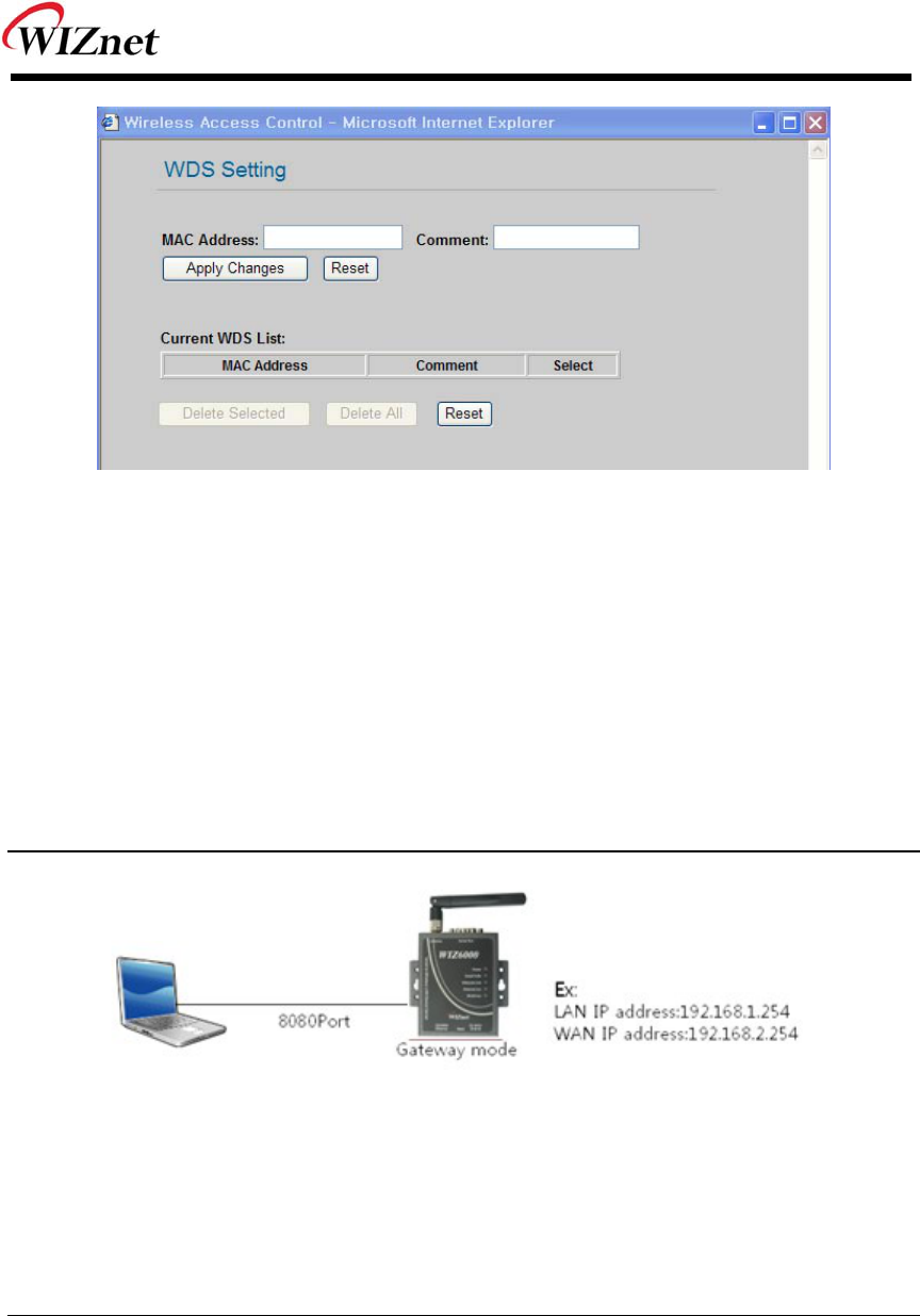
WDS Setting: : If AP mode is set as WDS Repeater, WDS Setting button is activated. WDS is
Wireless Distribution System that is working as a wi reless bridge between AP
and AP. If you click the “Setup” button, the page below appears.
WIZ6000 User’s Manual (WIZnet, Inc.) 19
Figure 18. WDS Setting
Input wireless MAC address of the device to be connected.
Apply Changes: Add the MAC address into the WDS list
Reset: Discard all changes in all fields.
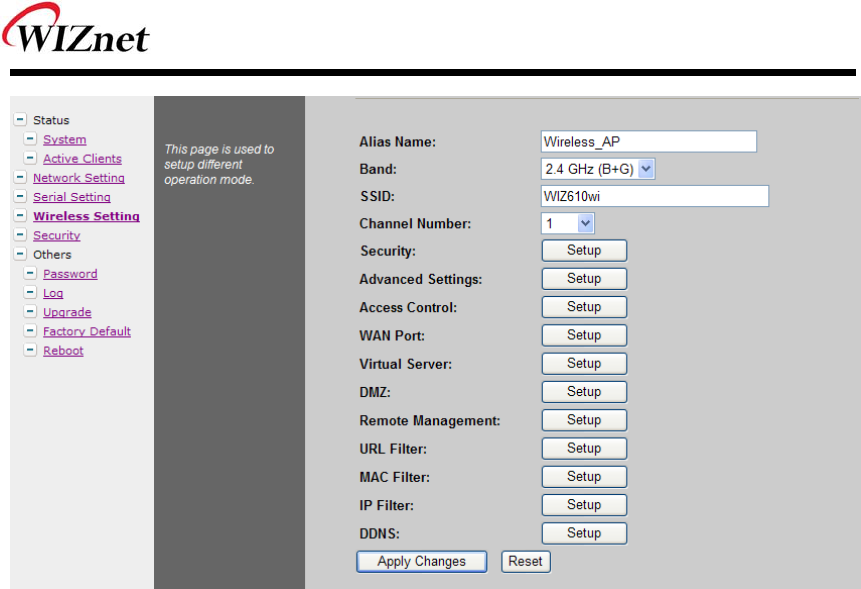
2.2.4.4 Gateway Setup
Notice
When changed to Gateway mode, wired netwo rk is disco nnected, It becau se WIZ6000’s wire
port act as WAN Port. So to solve this problem..
1. Connect WIZ6000 through wireless
2. Check WAN IP of Gateway mode setup page
3. Connect ‘http://WAN_IPaddress:8080 (8080 port)
First time it must be input ‘8080’, but next time no need to add ‘8080’
Gateway mode can be used when you want to conn ect to the Internet thro ugh an ADSL/Cable
Modem, or IP Sharing Device. By clicking the “Setup” button, you can configure your PPPoE,
DHCP Client, PPTP or Static IP settings
WIZ6000 User’s Manual (WIZnet, Inc.) 20
Figure 19. Gateway Setup
Alias Name: Refer to “2.2.4.3 Access Point Setup”.
Band: Refer to “2.2.4.3 Access Point Setup”.
SSID: Refer to “2.2.4.3 Access Point Setup”.
Channel Number: Refer to “2.2.4.3 Access Point Setup”.
Security: Refer to “2.2.4.3 Access Point Setup”.
Advanced Settings: Refer to “2.2.4.3 Access Point Setup”.
Access Control: Refer to “2.2.4.3 Access Point Setup”.
WAN Port : If configures WAN port. It configures the network environment for the connection
to WIZ6000.
WIZ6000 User’s Manual (WIZnet, Inc.) 21
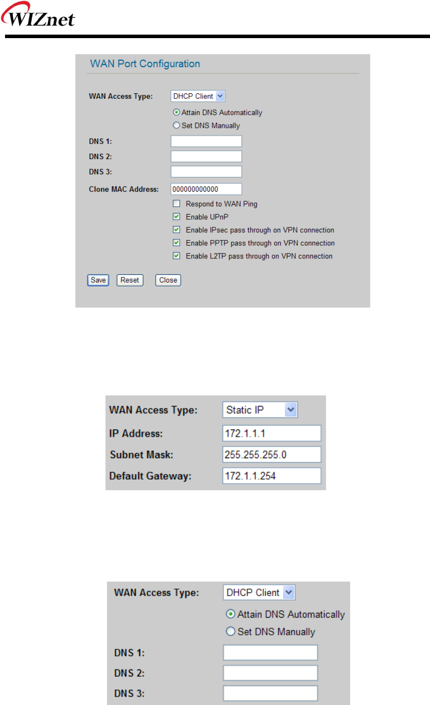
Figure 20. WAN Port Configuration
WAN Access Type
- Static IP : Manually input your IP address, Subnet Mask, Default Gateway and DNS.
- DHCP Client : An IP address can be acquired from a DHCP server. The DNS information
can be automatically acquired from a DHCP server or set manually
(Set DNS Manually)..

WIZ6000 User’s Manual (WIZnet, Inc.) 22
PPTP
- Virtual Server: Virtual Server also known as Port Forwarding associates a port number
with a private IP address(internal network). This technique allows clients from outside a
network to access devices within the LAN (internal network).
- DMZ: This feature allows one network user to be exposed to the Internet for special-
purposes such as Internet gaming or videoconferencing. DMZ hosting forwards all the
ports at the same time to one PC. The Port Range Forward enhances the security of
your device because only a range of ports are opened for access. DHCP should be
disabled in order to avoid any changes in your IP address. Static IP address is
recommended when using the DMZ
- Remote Management : Configure the port number for the connection to WIZ6000 from
a remote site. Default Port Number is set as “8080”.
- URL Filter: It enables to connect or disconnect to the specified URL.
- MAC Filter: Prevent access from a device with a specific MAC address.
- IP Filter: Prevent access from a device with a specific IP address
- DDNS : Once the DDNS server registers yours MAC address, your device can connect
to the internet regardless of your address. DDNS service can be provided by www.no-
ip.com. (You need to pay some fee). After registering some information at www.no-
ip.com, input your E-mail address and password in the figure shown below. When you
click the “Update” button, the status will change from “Not Connected” to “Connected”
Figure 21. WAN Access Type - PPPoE
WIZ6000 User’s Manual (WIZnet, Inc.) 23
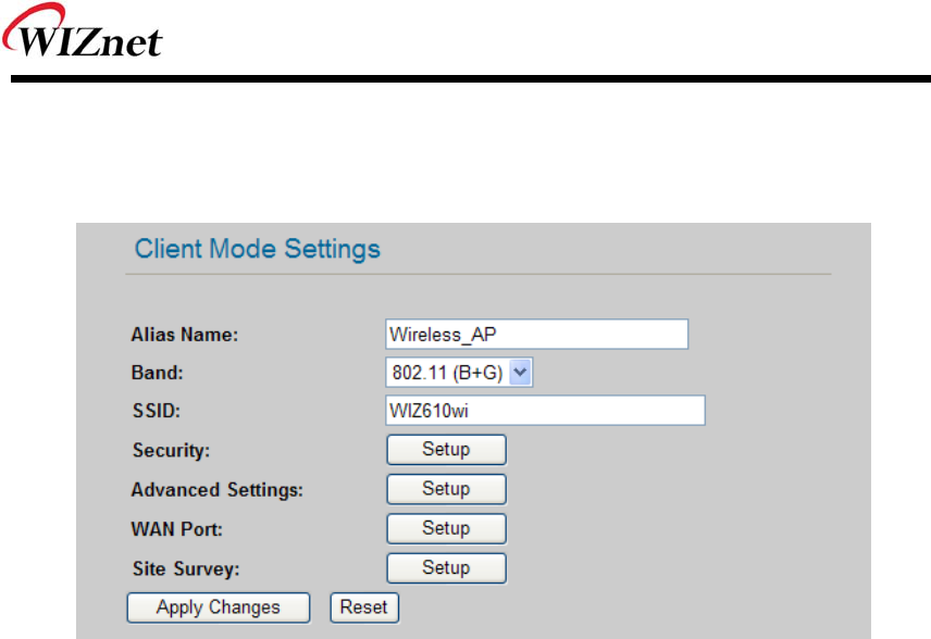
2.2.4.5 Client Setup
In client mode, WIZ610wi connects to an access point.
Figure 22. Client Setup
Alias Name: Input the name for WIZ6000.
Band: Select a communication protocol for your mod ule. It supports 802.11b, 802.11g and
802.11b/g mode.
SSID: Input the SSID of a n access poi nt. If y ou do n’t know you r SSID, you can u se the
“Site Survey” to search and connect to an AP.
Security: Configure security settings (these should match your AP’s settings)
Advanced Settings: Refer to “2.2.4.3 Access Point Setup”.
WAN Port: Set the Static or DHCP Client of the WIZ6000’s IP.
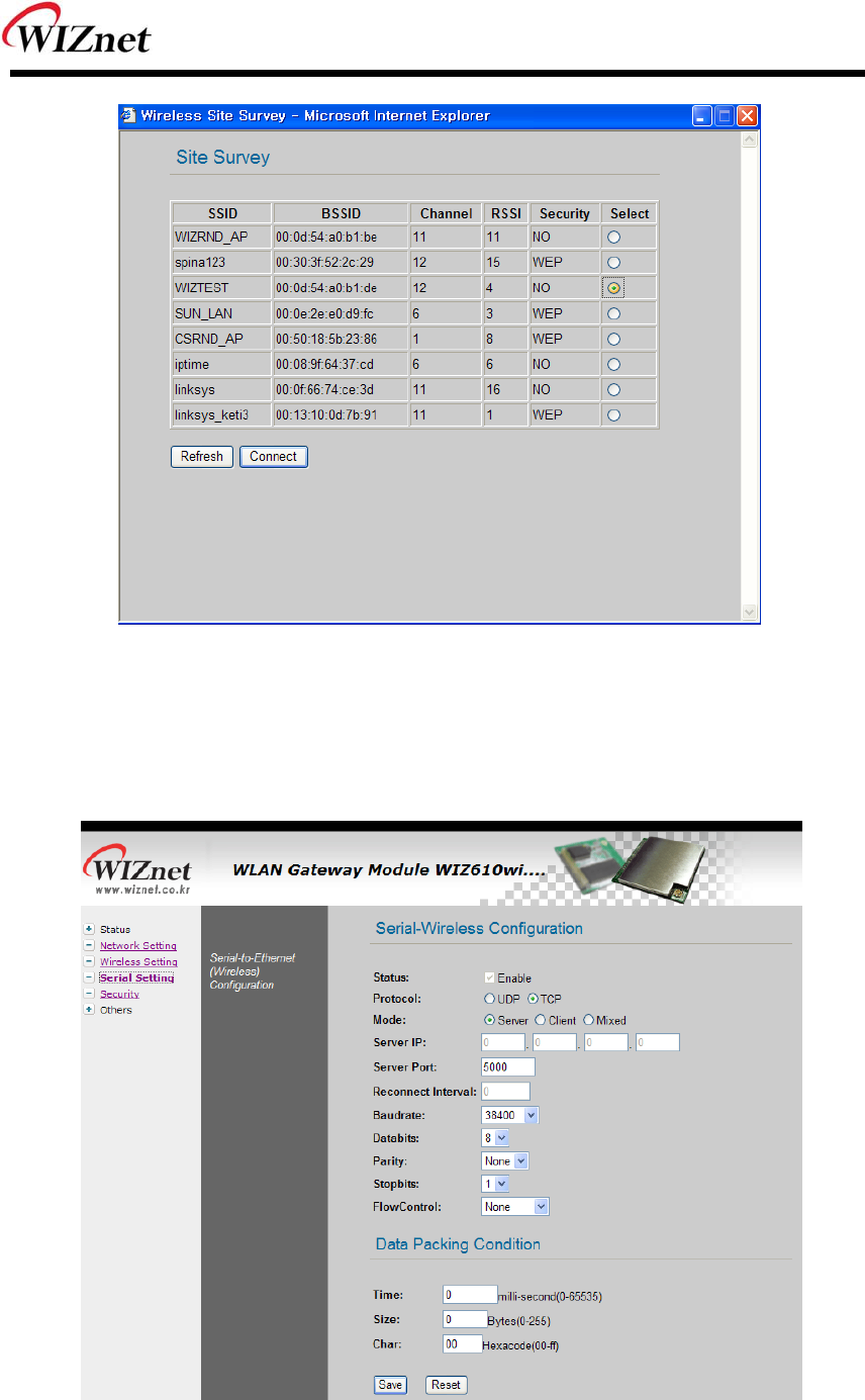
Site Survey: If you click t he “Site Su rvey’ button, all access points near your module are
listed as shown in the figure below. Please select one AP and click “Connect” button. If PC
or application device is set as DHCP Client, the AP will operates as its DHCP server and
WIZ6000 d oesn’t a ct a s DHCP Se rver. Wh en y ou conn ect to an AP with se curity
enabled ,the “Wi reless Secu rity Setup Page” will appear a utomatically to set-up you r
security settings. By using the “Site Survey”, Band, SSID and Security can be configured all
at the same time.
WIZ6000 User’s Manual (WIZnet, Inc.) 24
Figure 23. Site Survey
2.2.5 Serial Setting
For the ‘Serial to Wireless’ communication, you can configure serial parameters.
Figure 24. Serial to Ethernet Configuration

WIZ6000 User’s Manual (WIZnet, Inc.) 25
Status: Check this combo box to enable serial communication
Mode: Select one mode among Server, Client and Mixed.
This mode is to select the communication method based on TCP. TCP is the protocol which
establishes the connection before data communication. In server mode, WIZ6000 waits for
the connection from a clie nt. In client mode, WIZ60 00 operates as client at the TCP Client
mode on the process of connection, and tries to connect to the server ’s IP and Port. Mixed
modes supports both of Server and Client at the same time.
Below describes in details regarding each mode
- TCP server mode
In orde r to o perate thi s mode, Lo cal IP, Subnet, Gateway Addre ss and Local Po rt
Number should be co nfigured. In monitoring a pplications, the serve r mod e can be
useful since it can listen for any connection from clients, and establish a connection for
remote management.
1. A client connects to the WIZ6000 which is in TCP Server mode.
2. As the connection is established, data can be transmitted in both directions – from
the host to the WIZ6000, and from the WIZ6000 to the host
- TCP client mode
In TCP Client mode, your module will attempt to connect to a specified server.
In order to operate this mode, Local IP, Subnet, Gateway Addre ss, Serve r IP, and
Server port number should be set. If the server IP has a domain name, please use the
DNS function.
1. Whe n po wer i s supplied, WIZ6 000 board operating as T CP client mo de actively
establishes a connection to the server.
2. Once the connection is established, data can be transmitted in both directions – from
the host to the WIZ6000 and from WIZ6000 to the host
- Mixed mode
In this mod e, WIZ6000 normally operates as a T CP Server and waits for a connection
request from a client. However, if WIZ6000 re ceives data from the serial device before
connection is established, WIZ6000 changes to the client mode and sends the data to
the server. Therefore, in the mixed mode, the server mode has higher priority than the
client mode. Mixed mode t akes advantages of both client and serv er mode. The client
mode may b e used fo r sending out em ergency reports in an u rgent situation while the
server mode may be used for remote management.

WIZ6000 User’s Manual (WIZnet, Inc.) 26
Server IP : Input server IP.
Server Port : Input server port.
Reconnect Interval: Set the interval retrying connecting to server.
Baud rate: Configure serial communication speed.
Data bits: Configure data bits.
Parity: Configure parity checking option. (option: None, Odd, Even)
Stop bits: Configure stop bit option.(Option: 1, 2)
Flow Control: Configure flow control option. (option: none, Xon/Xoff, RTS/CTS)
Save : Save the configuration values.
Reset : Discard all changes in all fields
Data Packing Condition
You can specify how the serial data can be packed to be sent to the Ethernet. There are 3
delimiters - time, size and character. If all of them are set as ‘0’, whenever the serial data is
arrived, they are sent to the Ethernet immediately.
- Time: This field spe cifies the waiting time. Whe n there is n o more input from the se rial port,
the module will wait for the spe cified time and then se nd out the seri al d ata to the
network. Fo r example, if 2000 m s is specified, the module will send out the packet at
2000 ms after the last input from the serial port. If there is no dat a in the serial buffer, the
module will not send out any data packets. (‘0’: Function Disable)
- Size: This field specifies the size limit in the serial buffer. Once the serial buffer reaches this
limit, the dat a will be sent out to the Ethernet. If the serial buffer is greater than the size
limit, the module will create an Ethernet packet and store the extra data, and send out to
the Ethernet when the limit is reached again. (‘0’: Function Disable)
- Character: Register a chara cter to trigger th e conversion of se rial data to n etwork packets.
Whenever th e registe red character is insid e the serial buf fer, all the dat a before the
registered ch aracter i s se nt out to the network e xcluding the cha racter it self. The
character must be in Hexadecimal. (‘0’ : Function Disable)
If any one of these conditions is met, the data will be sent to Ethernet.
Ex) Delimiter: Size=10, Char=0x0D
Serial data : 0123456789abc
Ethernet data : 0123456789
☞ “abc” remains in the serial buf fer of t he module and will not be sent until the spe cified
size or character has been fulfilled.
WIZ6000 User’s Manual (WIZnet, Inc.) 27
2.2.6 Security Setup
Refer to “2.2.4.3. Access Point Setup’.
2.2.7 Others
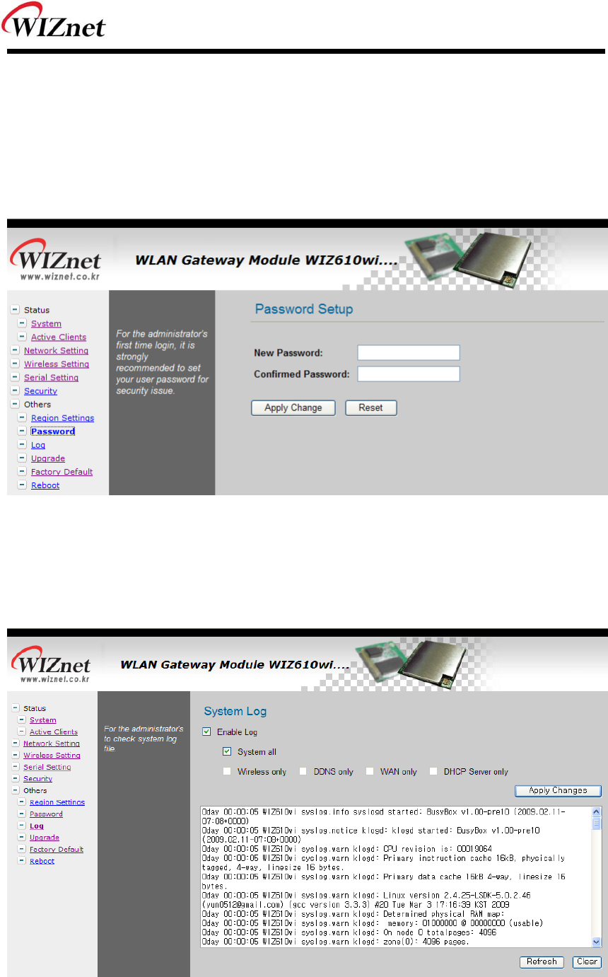
2.2.7.1 Password
You can change the password of WIZ6000
Figure 25. Password Setup
2.2.7.2 Log
The log information can b e saved. In o rder to use this functio n, check the combo box “Enabl e
Log”. The log will include information such as wireless, DDNS, WAN and DHCP.
Figure 26. System Log
WIZ6000 User’s Manual (WIZnet, Inc.) 28
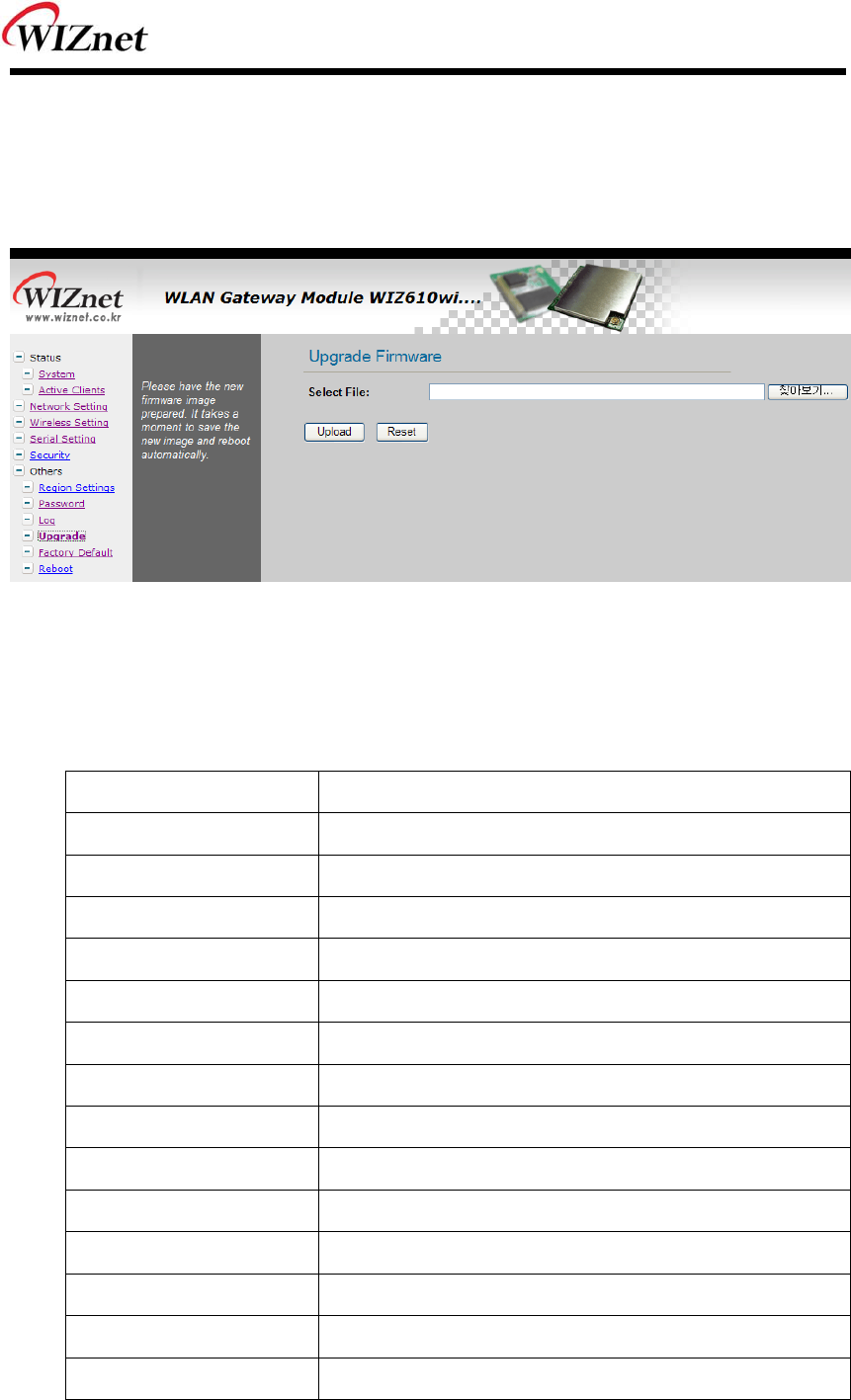
2.2.7.3 Upgrade
In this page, you can upgrade the firmware of your WIZ6000.
Browse the firmware file b y clicking the “Find” button. If you click “Upload” button after selecting
firmware file, the firmware starts uploading. This process will take about 60 seconds.
Figure 27. Upgrade Firmware
2.2.7.4 Factory Default
If you click the “Fa ctory Default” b utton, all se ttings value are resto red to the factory de fault
setting. The factory default values are shown below:
Field Default Value
IP Address 192.168.1.254
Subnet Mask 255.255.255.0
Default Gateway 0.0.0.0
DHCP Serv er
DHCP Client Range 192.168.1.2~192.168.1.100
DNS Server 0.0.0.0
Serial Status Disable
Serial Mode Server
Server IP 0.0.0.0
Server Port 5000
Baudrate 3840 0
Databits 8
Parity N one
Flow Control None
WIZ6000 User’s Manual (WIZnet, Inc.) 29
Wireless Mode AP
Alias Name Wireless_AP
Band 2.4GHz (B +G)
SSID WIZ61 0wi
Channel 1
AP Mode AP
Authentication Open system or Shared Key
Encryption N one
Fragment Threshold 2346
RTS Threshold 2346
Preamble Type Long Preamble
Beacon Interval 100ms
Inactivity Time 30000ms
Broadcast SSID Enable
WMM Enable
Password Admin
Log Disable
Table 9. Factory Default Value
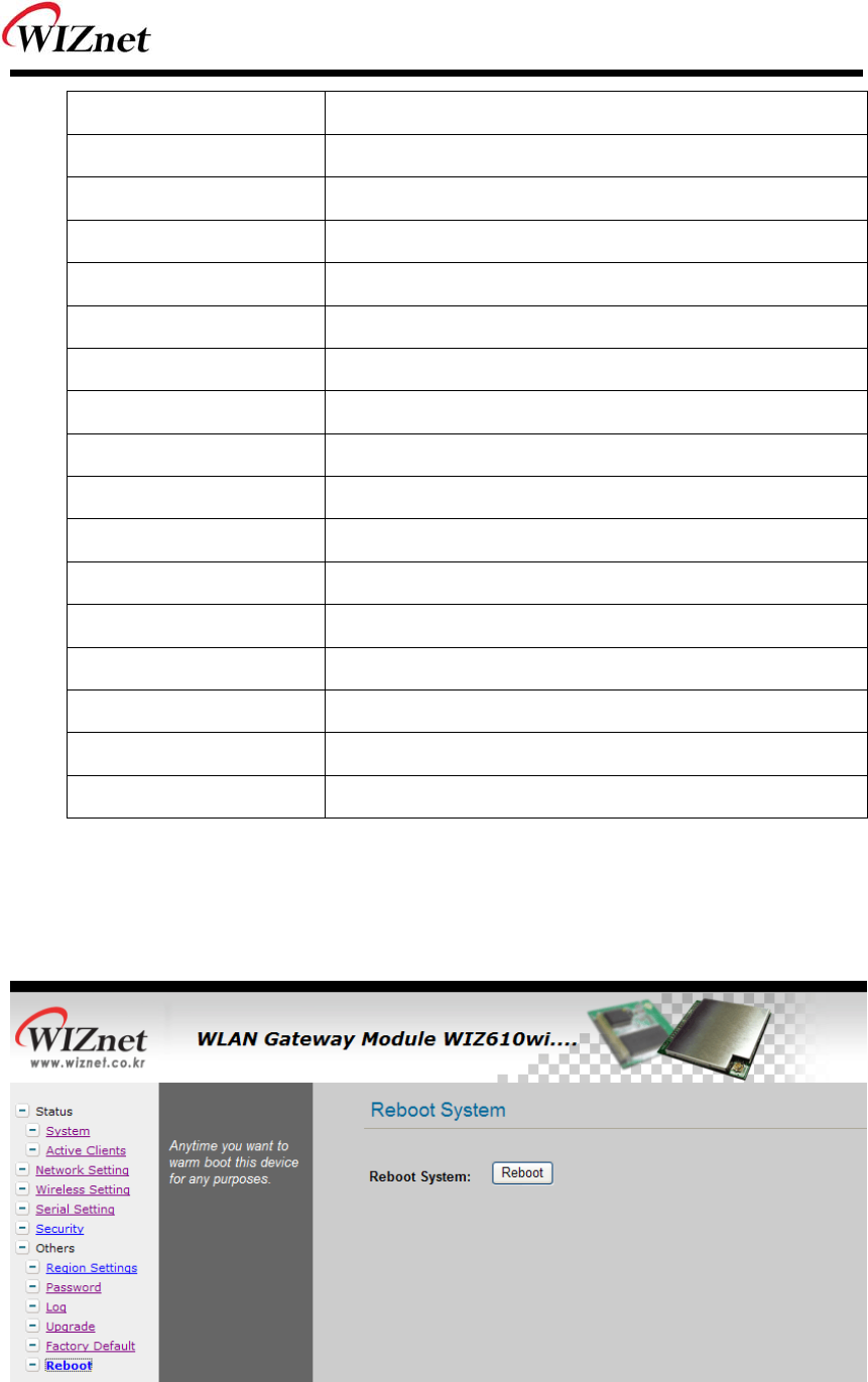
2.2.7.5 Reboot
In this page, you can reboot your module
Figure 28. Reboot System
WIZ6000 User’s Manual (WIZnet, Inc.) 30
3. Hardware Specification
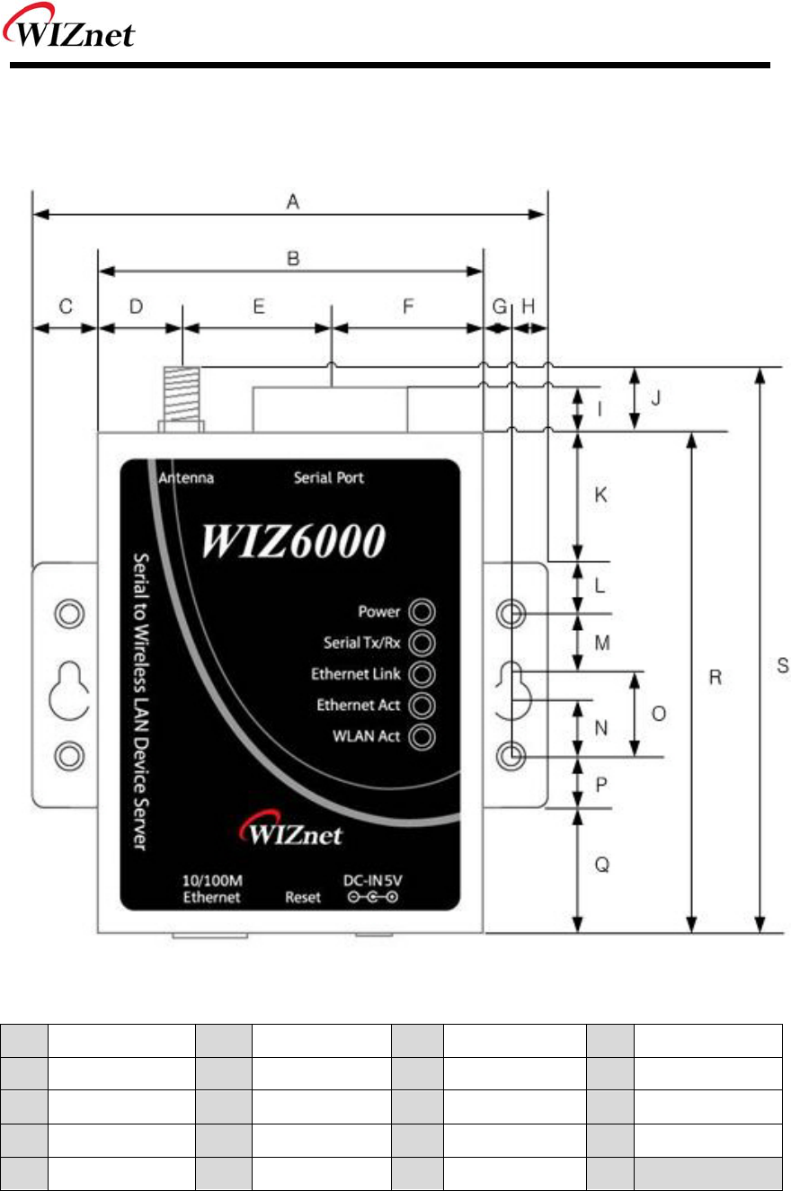
3.1 WIZ6000 Dimension
A 90.5 B 67.5 C 11.5 D 14.5
E 26.0 F 27.0 G 5.2 H 6.3
I 4.5 J 7.0 K 22.5 L 9.0
M 8.0 N 11.5 O 16.5 P 9.0
Q 22.5 R 87.5 S 94.5
Figure 29. WIZ6000 Dimensions (unit : mm)
WIZ6000 User’s Manual (WIZnet, Inc.) 31
3.2 Connector Specification
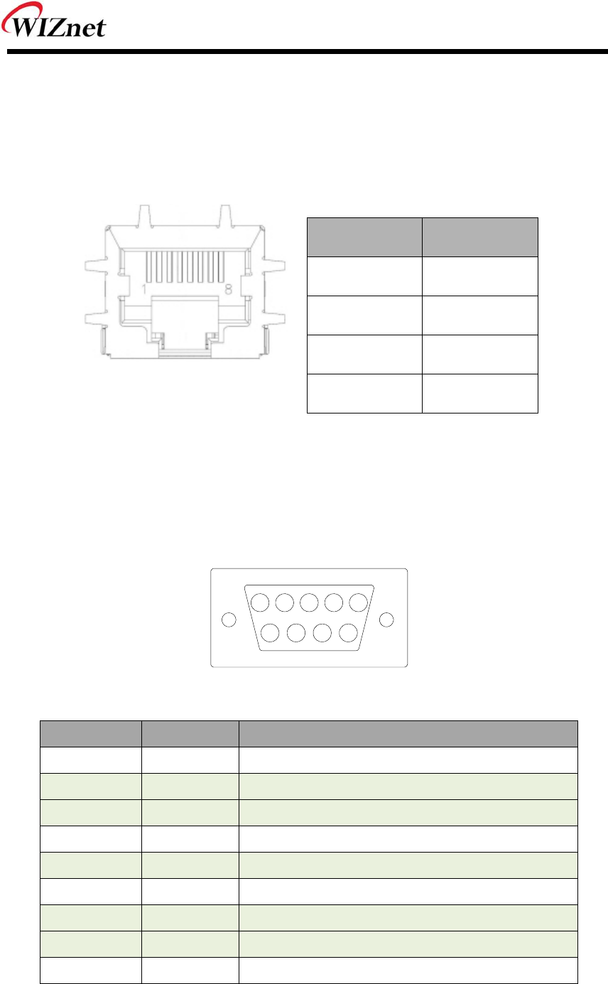
3.2.1 RJ-45 Connector
Ethernet port Pin outs
Pin Signal
1 TX+
2 TX-
3 RX+
6 RX-
Figure 30. RJ-45 PIN Assignment
3.2.2 RS-232C Connector
Serial port Pin outs
6 987
21 43 5
Pin Number Signal Description
1 H/W Trigger Hardware Trigger signal Input
2 RxD Receive Data
3 TxD Transmit Data
4 EXT_GND External Power Ground (Internally shorted to GND)
5 GND Ground
6 NC Not connect
7 RTS Request To Send
8 CTS Clear To Send
9 EXT_VCC External Power Input (5V)
Table 10. RS-232 PIN Assignment
WIZ6000 User’s Manual (WIZnet, Inc.) 32
4. Demonstration and Test
In this chapter, an example is provided f or you to test the functionality of WIZ6000. The te sting
environments are the followings:
<Hardware>
A PC equipped with a RS-232 serial port
WIZ6000 Device Server
Connect PC and module’s Ethernet port by using an Ethernet Cable
(Direct or Crossover)
Connect PC and module’s serial port by using a serial cable
<Software>
Hyper Terminal (or any other terminal program)
Step 1.
① Connect the PC and WIZ6000 by using a serial cable.
② Connect the PC and WIZ6000 by using an Ethernet cable.
③ Turn on the power switch of WIZ6000.
Step 2. : WIZ610wi Environment Setup
① On your PC, go to the “Network Setting” and connect to your WIZ60 00 in the “Wi reless
Network Connection”.
② In your web browser, input IP address of WIZ6000 (Default : 192.168.1.254).
If configuration page appears, click “Serial setup” menu and set the serial parameters.
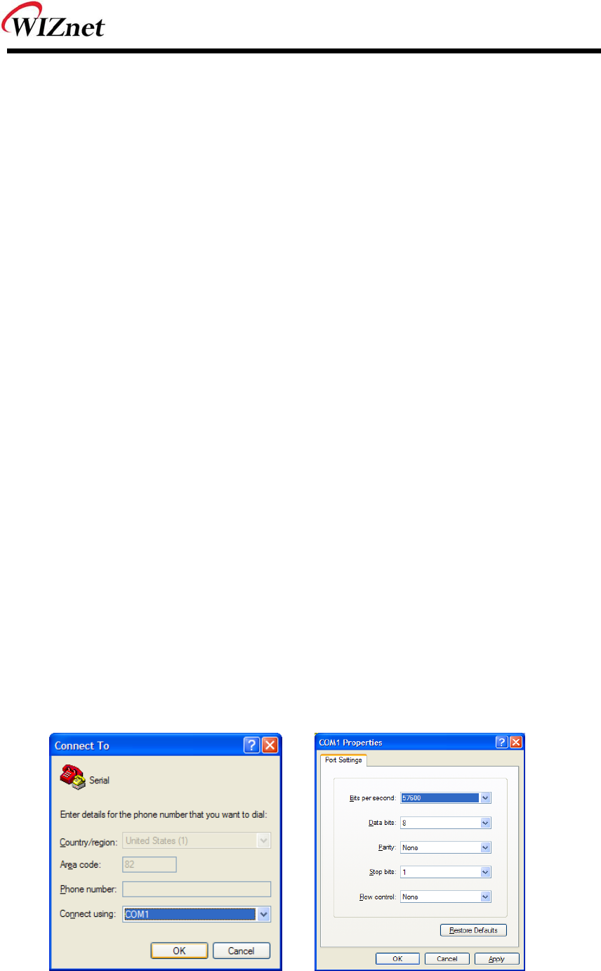
Step 3. : Data Transmission
① Execute terminal program at the PC. (Ex: Hyper Terminal)
② Set the baud rate as the same value of WIZ6000.
Figure 31. Serial Terminal Program configuration
WIZ6000 User’s Manual (WIZnet, Inc.) 33
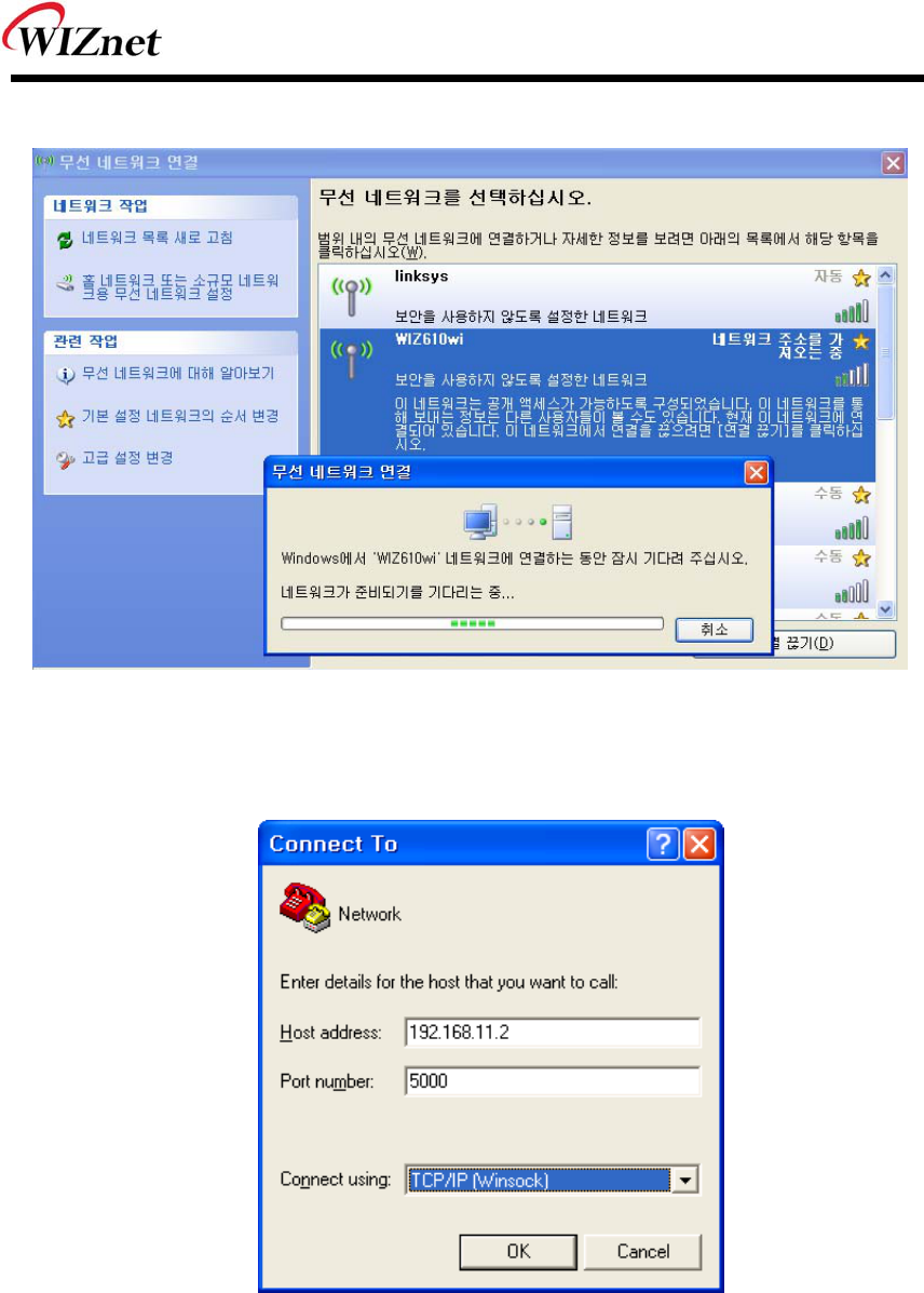
③ Connect to “WIZ6000” in the Wireless Network Setting of your PC
Figure 32. Wireless Network Connection
④ Execute one more terminal program, and set IP address and Port number.
Figure 33. Network Terminal Program configuration
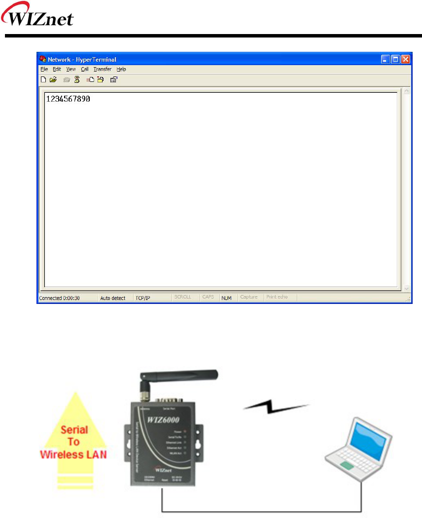
⑤ Input any chara cters i n the Hype r T erminal f or Seri al. (I n the exam ple belo w,
“01234567890” is input).
The same characters are outputted in the Hyper Terminal for Network.
A Serial to Wireless LAN test was performed. (Serial to Ethernet )
WIZ6000 User’s Manual (WIZnet, Inc.) 34
Figure 34. Received Data by Network Terminal Program
Figure 35. Serial to Wireless LAN 구성
⑥ In the same way, input an y character at t he screen of terminal p rogram for ne twork, and
check if same character is displayed at the screen for serial. ( Ethernet to Serial )
WIZ6000 User’s Manual (WIZnet, Inc.) 35
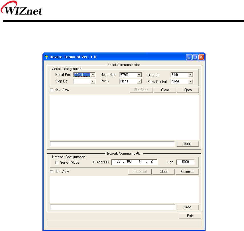
※ The above test can also be performed in a program called, “Device Terminal program”, which
is easy and simple to use.
Figure 36. Device Terminal Program
Device Terminal is a program which integrates both serial and network communications into one
user interface so that you can test your WIZnet gateway module easily.
As shown in above Figu re, the upper p art of the program allo ws you to config ure your serial
setting of WIZ6000. By clicking the “Open” button, serial communication is enabled.
The lower part of the p rogram allows you to configure the network settings. You can test both
TCP Clie nt a nd TCP Se rver modes at the sam e time. If the Server Mod e is enabled, Device
Terminal will operate as server mod e, and the WI Z6000 module will work as client mode. The
PC whe re th e Device T erminal is op erating w ill wo rk as a server, the IP address of the PC
should be set as Server IP of the module. If Se rver mode is not che cked, Device Terminal will
operate as cl ient mode, and the module as serve r. For the IP ad dress and po rt, please inp ut
your IP address and port number of WIZ6000 a nd click the “Connect” button to start a network
communication.
When serial and network terminals are connected, input any character in the Data Input window
and click “Send” button. You can check the data is transferred into the another window.

WIZ6000 User’s Manual (WIZnet, Inc.) 36
5. Serial Configuration
Serial Command Format
It is possible to configure WIZ6000 by using serial command.
RS-232C port’s Pin number 1 of WIZ6000 is Hardware trigger pin.
( ‘1’: H/W trigger disable, ‘0’: enable )
< Frame Format >
Command Frame format
Descriptor STX Command code Parameter ETX
Length(bytes) 1 2 Variable 1
Table 11. Serial Configuration Frame format
Reply Frame format
Descriptor STX Reply code Parameter ETX
Length(bytes) 1 1 Variable 1
Table 12. Serial Configuration Reply Frame format
STX & ETX
Setting Comments
STX ‘<’ : Hex = 3Ch
ETX ‘>’ : Hex = 3Eh
Table 13. Serial Configuration STX & ETX
Reply Code
Reply Comments
S Comm and was successful
F Comm and failed
0 Invalid STX
1 Invalid command

WIZ6000 User’s Manual (WIZnet, Inc.) 37
2 Invalid parameter
3 Invalid ETX
E Enter Serial Command Mode
Table 14. Serial Configuration Reply Code
Command Code
Com
mand
Get/
Set Comments Parameter Time
Network
RF Get Firmware
Version vx.x.x 1
RA Get MAC Address 0:Ethernet MAC address, 1:Wireless MAC address,
<0xx.xx.xx.xx.xx.xx_1xx.xx.xx.xx.xx.xx> 1
RI Get IP Address <Sxxx.xxx.xxx.xxx> 1
WI Set IP Address <xxx.xxx.xxx.xxx> 2
RS Get Subnet Mask <Sxxx.xxx.xxx.xxx> 1
WS Set Subnet Mask <xxx.xxx.xxx.xxx> 2
RG Get Gateway <Sxxx.xxx.xxx.xxx> 1
WG Set Gateway <xxx.xxx.xxx.xxx> 2
RD Get DHCP Server 1:Enable, 0:Disable
<Sx> 1
WD Set DHCP Server 1:Enable, 0:Disable
<x> 2
RH Get DHCP
Start/End IP
Start address_End address
<Sxxx.xxx.xxx.xxx_xxx.xxx.xxx.xxx> 1
WH Set DHCP
Start/End IP
Start address_End address
<xxx.xxx.xxx.xxx_xxx.xxx.xxx.xxx> 3
DL Get
Wireless
Active Client
List
MAC address_Channel_TxRate_RSSI
<Sxxxxxxxxxxxx_xx_xx_xx[:xxxxxxxxxxxx_xx_xx_xx:…]> 1
RL Get DHCP Client
List
<IP address_MAC address>
<Sxxx.xxx.xxx.xxx_xxxxxxxxxxxx[:xxx.xxx.xxx.xxx_xxxxxxxxxx
xx:…]>
1
WV Set DNS Server 1:Enable, 0:Disable 1

WIZ6000 User’s Manual (WIZnet, Inc.) 38
<1:xxx.xxx.xxx.xxx[_xx.xx.xx.xx]> or<0>
RV Get DNS Server 1:Enable, 0:Disable_DNS Server IP address
<Sx_xxx.xxx.xxx.xxx[_xx.xx.xx.xx]> or<0> 1
RT Get WAN Port
0:Static, 1:DHCP Client, 2:PPPoE, 3:PPTP
-Static: 0_Ipaddress_Subnet_Gateway_DNS
<S0_xxx.xxx.xxx.xxx_xxx.xxx.xxx.xxx_xxx.xxx.xxx.xxx_xxx.xx
x.xxx.xxx>
-DHCP Client: 1_IPaddress_Subnet_Gateway
<S1_xxx.xxx.xxx.xxx_xxx.xxx.xxx.xxx_xxx.xxx.xxx.xxx>
PPPoE: 2_UserName_Password
<S2_User Name_Password>
-PPTP: 3_IP_Subnet_Gateway_ServerIP_UserName_
Password
<S3_xxx.xxx.xxx.xxx_xxx.xxx.xxx.xxx_xxx.xxx.xxx.xxx_xxx.xx
x.xxx.xxx_UserName_Password>
2
WT Set WAN Port
0:Static, 1:DHCP Client, 2:PPPoE, 3:PPTP
-Static: 0_Ipaddress_Subnet_Gateway_DNS
<0_xxx.xxx.xxx.xxx_xxx.xxx.xxx.xxx_xxx.xxx.xxx.xxx_xxx.xxx.
xxx.xxx>
-DHCP Client: 1
<1>
PPPoE: 2_UserName_Password
<2_User Name_Password>
-PPTP: 3_IP_Subnet_Gateway_ServerIP_UserName_
Password
<3_xxx.xxx.xxx.xxx_xxx.xxx.xxx.xxx_xxx.xxx.xxx.xxx_xxx.xxx.
xxx.xxx_UserName_Password>
1
Wireless
DB Get Wireless
Band
0: 11b+g, 2: 11b, 3:11g, 6: n, 9:b+g+n
<Sx> 1
GB Set Wireless
Band
0: 11b+g, 2: 11b, 3:11g, 6: n, 9:b+g+n
<x> 20
DO Get Operation
Mode
0:AP, 1:Gateway, 2: AP+WDS, 3:Client
<Sx> 1
GO Set Operation 0:AP, 1:Gateway, 2: AP+WDS, 3:Client 45

WIZ6000 User’s Manual (WIZnet, Inc.) 39
Mode <x>
DS Get SSID 1~32 chars
<Sxxxx~> 1
GS Set SSID 1~32 chars
<xxxx~> 1
DC Get Channel Auto_0, 1~13
<Sx> 1
GC Set Channel Auto_0, 1~13
<x> 2
DW Get WDS
1:Master,2:Slave
_count_MACaddress_Comment[_MACaddress_Comment_...]
<Sx_x_xxxxxxxxxxxx_xxx~>
1
GW Set WDS
1:Master, 2:Slave_1:add,
2:delete_count_MACaddress_Comment[_MACaddress_
Comment_..]
<x_x_x_xxxxxxxxxxxx_xxx~>
1
DP Get Tx Power 0: off, 1-16: power(dBm),
<Sxx> 1
GP Set Tx Power 0: off, 1-16: power(dBm),
<xx> 2
DR Get Data Rate <Sxx> 1
GR Set Data Rate <xx> 3
DH Get Broadcast
SSID
0:Enable, 1:Disable
<Sx> 1
GH Set Broadcast
SSID
0:Enable, 1:Disable
<x> 1
DM Get WMM 1:Enable, 0:Disable
<Sx> 1
GM Set WMM 1:Enable, 0:Disable
<x> 1
DA Get MAC Access
Control
0:Disable,1:AllowListed,2:DenyListed[_count[_MACaddress_C
omment]]
<Sx_x_xxxxxxxxxxxx_xxx~>
1
GA Set MAC Access
Control
0:Disable,1:AllowListed,2:DenyListed[_1:add,2:delete_count_
MACaddress_Comment] 5

WIZ6000 User’s Manual (WIZnet, Inc.) 40
<x_x_x_xxxxxxxxxxxx_xxx~>
DI Get Site Survey SSID_BSSID_Channel_RSSI_Security
<Sxxxx_xxxxxxxxxxxx_xx_xx_x> 15
DN Get Alias Name Alias Name
<Sxxx> 1
GN Set Alias Name Alias Name, Max Length: 29bytes
<xxx> 1
QP Get
Module
Status
Checking
connection status_SSID_BSSID_CHAN_RATE_RSSI
Conn_status: ‘0’ is not connected, ‘1’ is connected.
<Sx_xxxx_xxxxxxxxxxxx_xx_xxM_xx>
2
Security
DU Get Security
Status
AuthMode_Encrypt[_KeyLength_KeyFormat_KeyValue_radius
Passwd_radiusIP_radiusPort]
AuthMode: 0(Open or Shared), 1(Open), 2(802.1x), 3(Shared),
4(WPA), 5(WPA-PSK), 6(WPA2), 7(WPA2-PSK),
Encrypt: 0(None),1 (WEP), 2(TKIP), 3(AES), 4(TKIP_AES)
KeyLength: 0(None), 1(WEP64), 2(WEP128)
KeyFormat(WEP): 0(Ascii), 1(Hex)
KeyFormat(WPA-PSK): 0(Passphrase), 1(Hex)
<Sx_x_x_x_x_x_x_x>
1
GU Set Security
Control
AuthMode_Encrypt[_KeyLength_KeyFormat_KeyValue_radius
Passwd_radiusIP_radiusPort]
AuthMode: 0(Open or Shared), 1(Open), 2(802.1x), 3(Shared),
4(WPA), 5(WPA-PSK), 6(WPA2), 7(WPA2-PSK),
Encrypt: 0(None),1 (WEP), 2(TKIP), 3(AES), 4(TKIP_AES)
KeyLength: 0(None), 1(WEP64), 2(WEP128)
KeyFormat(WEP): 0(Ascii), 1(Hex)
KeyFormat(WPA-PSK): 0(Passphrase), 1(Hex)
(WPA-PSK KeyValue:8~63byte)
<x_x_x_x_x_x_x_x>
30
Serial
RK Get Protocol TCP_0, UDP_1
<Sx> 2

WIZ6000 User’s Manual (WIZnet, Inc.) 41
WK Set Protocol TCP_0, UDP_1
<x> 1
RM Get Mode 0:Client, 1:Mixed, 2:Server
<Sx> 2
WM Set Mode 0:Client, 1:Mixed, 2:Server
<x> 1
RX Get Server IP Server IP address
<Sxxx.xxx.xxx.xxx> 1
WX Set Server IP Server IP address
<xxx.xxx.xxx.xxx> 2
RP Get Port 0~65535
<Sxxxxx> 1
WP Set Port 0~65535
<xxxxx> 1
RB Get
Baudrate_Dat
aBit_Parity_F
low_Stopbits
eg. [Baudrate]1: 115200, 2: 57600,
3: 38400, 4: 19200, 5: 9600,
6: 4800, 7: 2400,8: 1200
[data byte] 7: 7bit, 8bit
[parity] 0: no parity, 1: Odd, 2: Even
[Flow] 0: no, 1: Xon/Xoff, 2: RTS/CTS
[Stopbits]; 1: 1stop, 2:2stop
<Sxxxxx>
2
WB Set
Baudrate_Dat
aBit_Parity_F
low_Stopbits
eg. [Baudrate]1: 115200, 2: 57600,
3: 38400, 4: 19200, 5: 9600,
6: 4800, 7: 2400,8: 1200
[data byte] 7: 7bit, 8bit
[parity] 0: no parity, 1: Odd, 2: Even
[Flow] 0: no, 1: Xon/Xoff, 2: RTS/CTS
[Stopbits]; 1: 1stop, 2:2stop
<xxxxx>
5
QT Get Time 0~65535
<Sxxxxx> 1
OT Set Time 0~65535
<xxxxx> 1
QS Get Size 0~255
<Sxxx> 1

WIZ6000 User’s Manual (WIZnet, Inc.) 42
OS Set Size 0~255
<Sxxx> 1
QC Get Char 00~ff
<Sxx> 1
OC Set Char 00~ff
<xx> 1
QI Get Inactivity
Time
00~60
<Sxx> 1
OI
Set
Inactivity
Time
00~60
<xx> 1
RC Get
Connection
Status(Server
:Client)
0: Not Connect, 1:Connect
<Sx> 1
Others
WF Set Factory
Default <WF> 55
WR Set Restart <WR> 55
error code
S <S> or <Sxx…> Commend is successfully applied
F <F> Failed to apply
0 <0> "<" is wrong
1 <1> There is not in command list
2 <2> Wrong Parameter factor
3 <3> ">" is wrong
4 <4> Do not work in current mode
5 <5 >
No more add list.
-Limit-
*WDS: 4 list
*ACL: 16 list

WIZ6000 User’s Manual (WIZnet, Inc.) 43
Notice
If input "_" in fact, should input"__" instead of "_".
For example SSID, PSK etc.
<DS> --> <S11__22>: SSID: 11_22
<GS11_22> --> <S>: SSID: 11_22
<QP> --> <S1_11__22_000102030405_...>: SSID: 11_22
If multi command input, response time be delayed
For example DA, GA, DW, GW
Security Available mode
AP/GW Mode
AuthMode: 0-7
EncryptTyp e: 0-3
Client Mode
AuthMode: 1,3,5,7
EncryptTyp e: 0,1,4
**Security Example parameter
<GU5_2_0_0_12345678>
<GU4_2_0_0_12345678_abcd_192.168.123.111_1812>

WIZ6000 User’s Manual (WIZnet, Inc.) 44
6. Warranty
WIZnet Co., Ltd offers the following limited warranties applicable only to the o riginal purchaser.
This offer is non-transferable.
WIZnet warrants our products and its parts against defects in materials and workmanship under
normal use for period of standard ONE(1) YEAR for the WIZ6000 board and labor warranty after
the date of original ret ail purchase. During this pe riod, WIZnet will repair or repl ace a defective
products or part free of charge.
Warranty Conditions:
1. The warranty applies only to products distributed by WIZnet or our official distributors.
2. The warranty applies only to defects in material or workmanship as mentioned above in
6.Warranty. The warra nty applies only to defects which occu r duri ng normal use and
does not extend to dam age to pro ducts or parts which results from alternation, repair,
modification, faulty installation or service by anyone other than som eone authorized by
WIZnet Inc. ; damage to products or parts caused by accident, abuse, or mi suse, poor
maintenance, mishandling, misapplication, or used in violation of instructions furnished
by us ; damage occurring in shipment or any damage caused by an act of God, such as
lightening or line surge.
Procedure for Obtaining Warranty Service
1. Contact an authorized distributors or dealer of WIZnet Inc. for obtaining an RMA (Return
Merchandise Authorization) request form within the applicable warranty period.
2. Send the products to th e dist ributors or d ealers togethe r with the complet ed RMA
request fo rm. All produ cts returned fo r warr anty mu st be carefull y rep ackaged in the
original packing materials.
3. Any service issue, please contact to sales@wiznet.co.kr