WIZNET WIZFI220 Wireless LAN Module User Manual
WIZNET Co., LTD. Wireless LAN Module Users Manual
UserManual.wiki
>
WIZNET
>
WIZFI220 User Manual
Users Manual
Navigation menu
Upload a User Manual
Namespaces
Wiki Guide
HTML
PDF
Info
Views
User Manual
Discussion / Help
Navigation


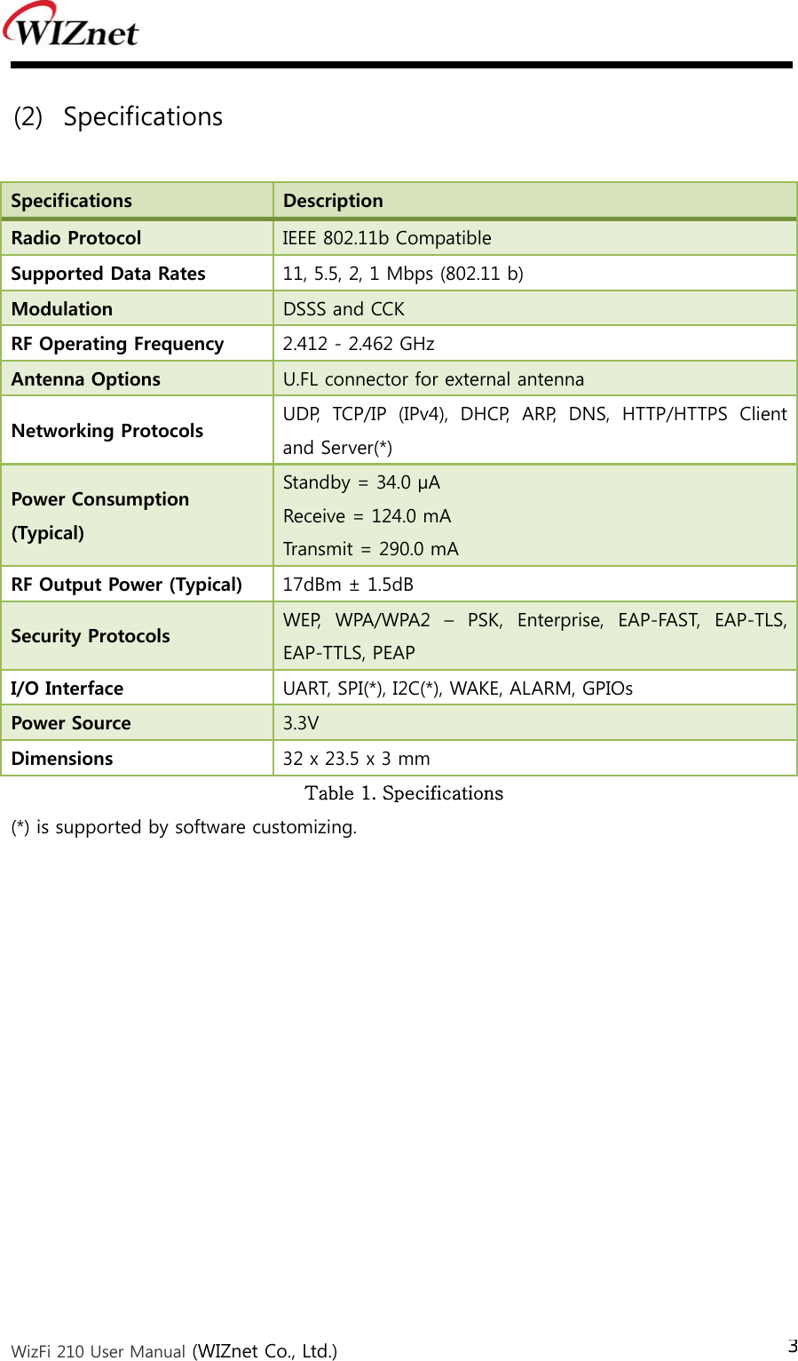
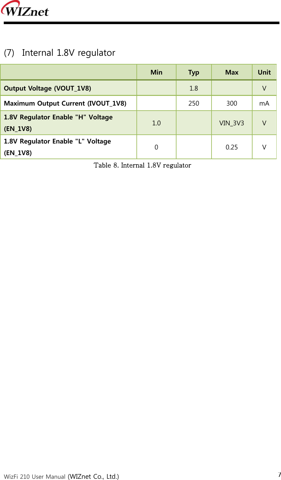
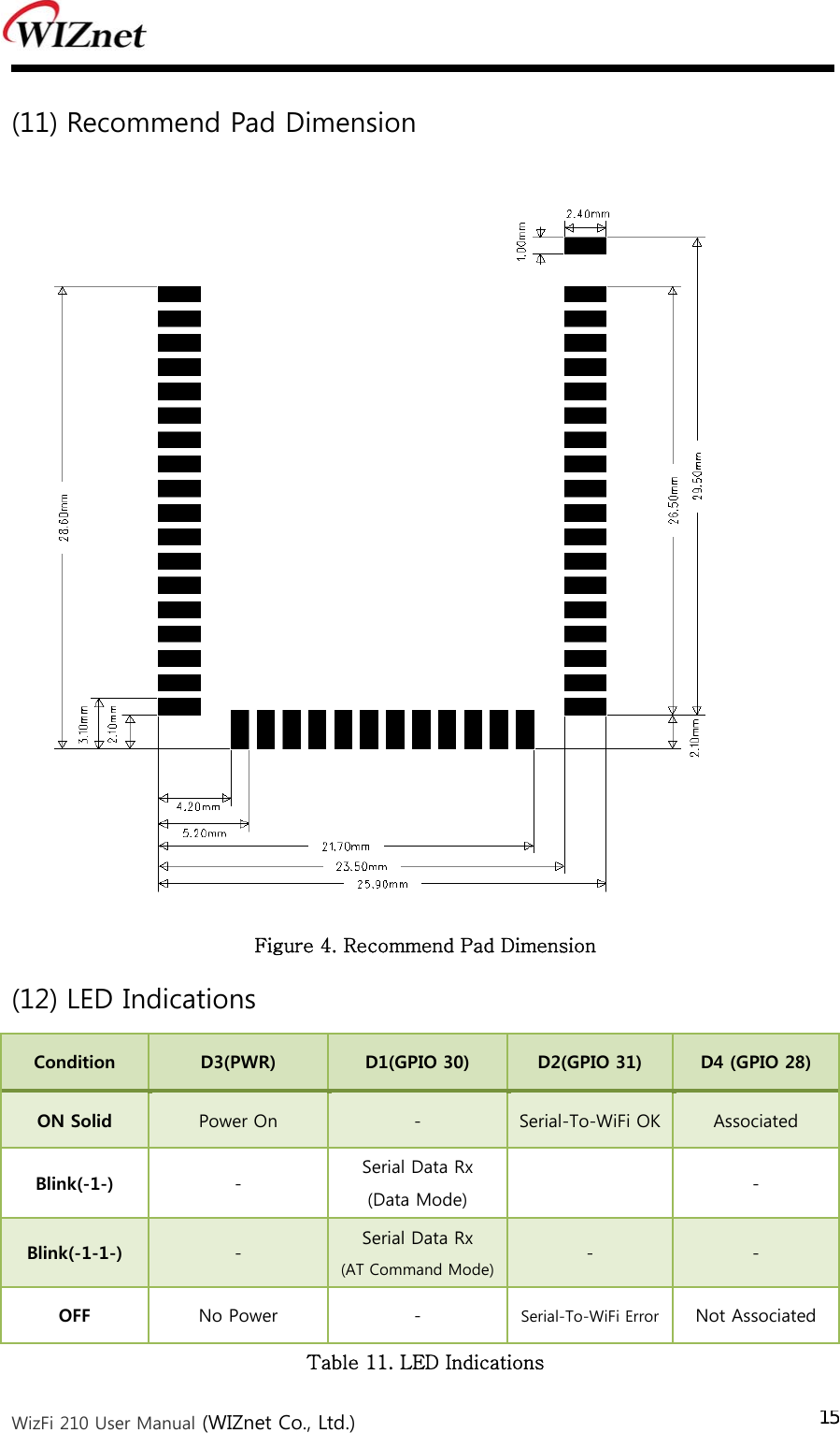
![WizFi 210 User Manual (WIZnet Co., Ltd.) 1 1. Overview The WizFi220 family of fully certified modules offers a quick, easy, and cost effective way for device and appliance manufacturers to add Wi-Fi capabilities to their products. The module provides serial UART interface which enables connection to any embedded design utilizing an 8/16/32-bit microcontroller via simple commands. The WizFi220 is an ideal solution for organizations with limited or no Wi-Fi or RF expertise, as it not only dramatically reduces RF design time but also removes the burden of testing and certification; allowing customers to focus on their core application, product, or expertise. The module supports data rates up to 11 Mbps, and is compliant with 802.11b. The WizFi220 provides customers the mean to evaluate the capabilities of ultra-low power wireless system-on-a-chip and the Serial to Wi-Fi embedded software for Wi-Fi networks. The Serial to Wi-Fi embedded software allows devices and appliance manufacturers to easily add Wi-Fi capabilities to their products with minor impact on the host microcontroller firmware. The WizFi220 provides all the hardware and software necessary to quickly set up a serial (UART) based link to a PC or external microcontroller. The WizFi220 is a RF-enhanced Product. Except for [RF Output Power], the WizFi220 is similar in management and development to the WizFi210. In other words, the WizFi220 will consume more power but it has the improved WiFi range.](https://usermanual.wiki/WIZNET/WIZFI220/User-Guide-1490506-Page-8.png)

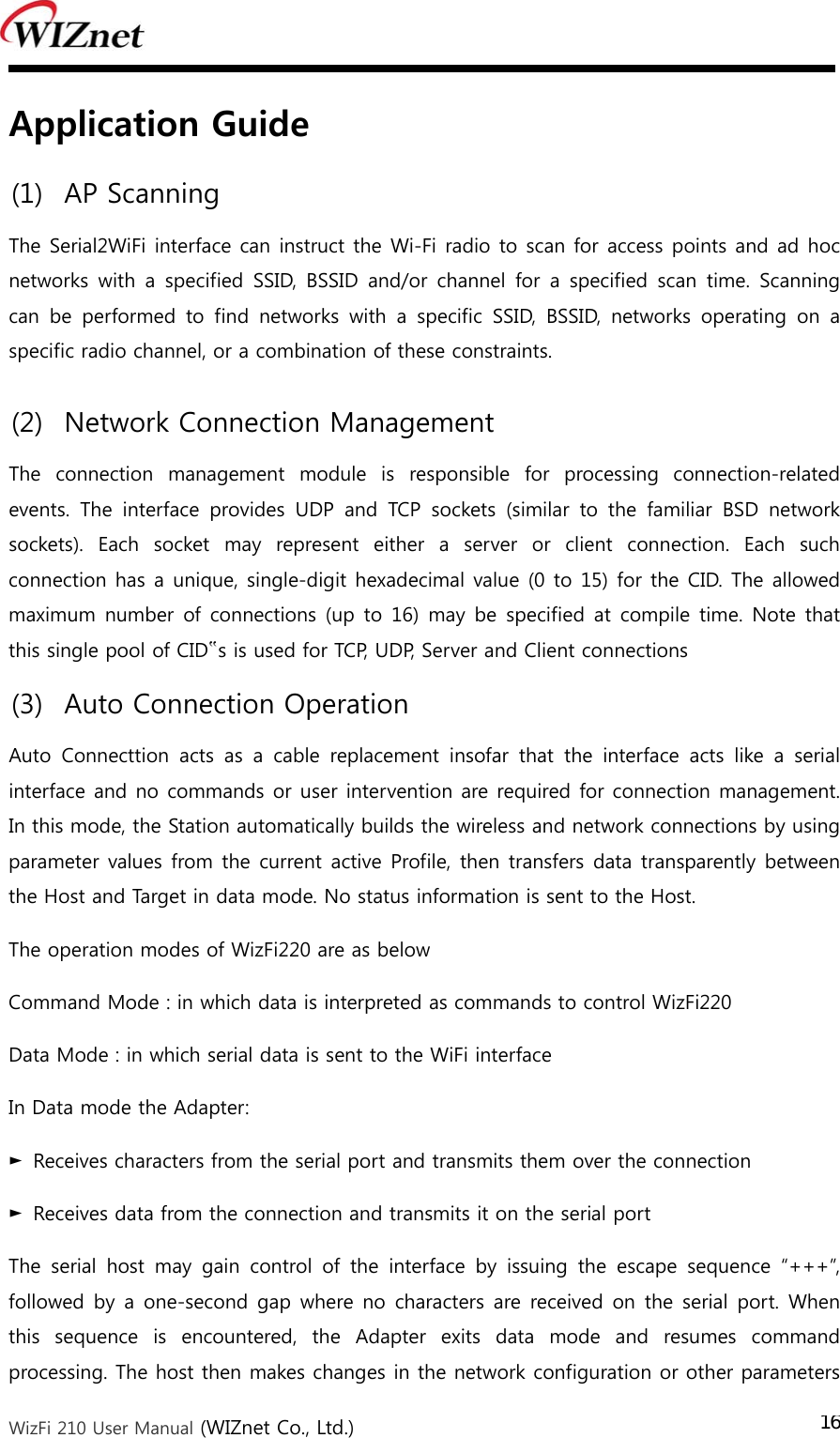
![WizFi 210 User Manual (WIZnet Co., Ltd.) 17as needed. However, the Adapter does not accept any new TCP/UDP client/server or data connection requests. The ATO command (terminated by the ASCII character “O”, not the number 0) is used to return to data mode. Applying the “AT+XEHT=1” command (Enable Hardware Trigger), you can change between data mode and command mode using GPIO 10, without escape sequence (“+++”). Using D2(GPIO 31), D4(GPIO 28) of WizFi220, you can see if the WizFi220 is associated to the AP and if serial-to-wifi network channel is normal. And applying the “AT+XDUM=1” command (Disable UART Message), all UART messages are blocked in data mode. In this situation, you have to check the signal of GPIO 28 and GPIO 31 to know disassociation or network connection closed. In data mode, the Nagle Algorithm Wait Time can be used to buffer any characters to be sent, in order to avoid sending a large number of packets with small payloads onto the network. The wait time is specified in units of 10 milliseconds. This functionality is available for both UDP and TCP connections. (4) Response Codes The possible responses sent by the Adapter to the serial host are described below. The Response Codes can be distinguished into codes resulting from the AT Command or not. There are Carriage Return(\r, 0x0d) and Line Feed(\n, 0x0a) above and below ASCII STRING. If you send “at” string and Line Feed to the WizFi220, at + Line Feed (0x61 0x74 0x0d) You can see the following data. at + Line Feed (0x61 0x74 0x0d) + \r\n[OK]\r\n (0x0d 0x0a 0x5b 0x4f 0x4b 0x5d 0x0d 0x0a) No ASCII CHAR Response ASCII STRING Meaning 1 0 S2W_SUCCESS [OK] Command Request Success. 2 1 S2W_FAILURE [ERROR] Command Request Failed. 3 2 S2W_EINVAL [ERROR: INVALID INPUT] Invalid Command or Option or Parameter. 4 3 S2W_SOCK_FAIL [ERROR: SOCKET FAILURE] Socket Operation Failed. 5 4 S2W_ENOCID [ERROR: NO CID] All allowed CID’s in use, so there was no CID to assign to the new](https://usermanual.wiki/WIZNET/WIZFI220/User-Guide-1490506-Page-24.png)
![WizFi 210 User Manual (WIZnet Co., Ltd.) 18connection. 6 5 S2W_EBADCID [ERROR: INVALID CID] Invalid Connection Identifier. 7 6 S2W_ENOTSUP [ERROR: NOT SUPPORTED] Operation or Feature not supported. 8 7 S2W_CON_SUCCESS [CONNECT <CID> <info>]TCP/IP connection successful. <CID> = the new CID in hexadecimal format. 9 8 S2W_ECIDCLOSE [DISCONNECT <CID>] TCP/IP connection with the given CID is closed. This response is sent to the host when a connection is closed either by the remote device or by the serial host. 10 9 S2W_LINK_LOST [DISASSOCIATED] Not associated to a wireless network. 11 A S2W_DISASSO_EVT [Disassociation Event] Wireless network association lost. Table 12. Response Codes (5) Use of GPIO10 If you click the GPIO10 button twice consecutively, the WizFi220 is restored to factory default. And if you click the GPIO10 button three times consecutively, the WizFi220 is restored to factory default and will change to ad hoc mode to configure the WizFi220 via WiFi. (IP:192.168.1.254/Subnet:255.255.255.0/Gateway:192.168.1.1) Figure 5. Factory Default and ad hoc mode As previously described, GPIO10 is used for data/command mode transition by applying “AT+XEHT=1” command. But there should be no UART input in 300mS before and after sending signal to GPIO10 for mode transition time and buffer processing time.](https://usermanual.wiki/WIZNET/WIZFI220/User-Guide-1490506-Page-25.png)
![WizFi 210 User Manual (WIZnet Co., Ltd.) 19(6) AT Command example AT Command examples are described below. In this sample application, the WizFi220 associate to the AP and open the serial-to-wifi channel automatically after reboot. Description of each command is in the next chapter. No MCU → WizFi220 (AT Command) WizFi220 → MCU (Echo and Result String) Description 1 AT+WD AT+WD [OK] Disassociate 2 AT+WWPA=12345678 AT+WWPA=12345678 [OK] Set WPA passphrase 3 AT+NDHCP=1 AT+NDHCP=1 [OK] Enable DHCP 4 AT+WAUTO=0,WizFiAP,,0 AT+WAUTO=0,WizFiAP,,0 [OK] Set WiFi Configuration 5 AT+NAUTO=1,1,,4000 AT+NAUTO=1,1,,4000 [OK] TCP Server Mode(4000) 6 ATC1 ATC1 [OK] Auto Connect on next reboot 7 AT+XEHT=0 AT+XEHT=0 [OK] Disable Hardware Trigger 8 AT+XDUM=1 AT+XDUM=1 [OK] Disable UART Message 9 AT&Y0 AT&Y0 [OK] Set Default Profile 10 AT&W0 AT&W0 [OK] Save Profile Table 13. AT Command Example](https://usermanual.wiki/WIZNET/WIZFI220/User-Guide-1490506-Page-26.png)
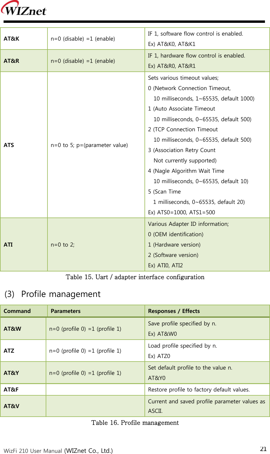
![WizFi 210 User Manual (WIZnet Co., Ltd.) 203. AT Commands This section provides a list of Serial2WiFi commands and their effects. Parameters are generally ASCII characters, e.g. ATEn with n=1 is the series of ASCII characters ‘A’, ‘T’, ‘E’, and ‘1’. Where some parameters are optional, mandatory parameters are denoted by < > and optional parameters by [ ]. If a parameter is mandatory, any associated sub-parameters are also mandatory; sub-parameters of an optional parameter are optional. Parameters must always be provided in the order given in the command description. When an optional parameter is not supplied, the comma delimiters must still be included in the command. Every command starts with the characters “AT”; any other initial characters will cause an error to be returned. Command Response: In most cases, valid commands return the characters OK. Invalid inputs return ERROR: INVALID INPUT. Some commands may be not supported depending on the version (1) Command interface Command Parameters Responses / Effects AT “OK” ATE n=0 (disable) =1 (enable) IF 1, echo all input. Ex) ATE0, ATE1 ATV n=0 (disable) =1 (enable) IF 1 responses are ASCII, else numerical codes. Ex) ATV0, ATV1 Table 14. Command interface (2) UART / adapter interface configuration Command Parameters Responses / Effects ATB <baudrate>[[,<bitsperchar>] [,<parity>][,<stopbits>]] UART parameters are immediately reset to values provided.(9600, 19200, 38400, 57600, 115200, 230400) Parity is n for no parity, e for even parity and o for odd parity. Allowed values are 5, 6, 7 or 8 bits/character, with 1 or 2 stop bits (1.5 in the case of a 5-bit character). Ex) ATB=9600,8,n,1](https://usermanual.wiki/WIZNET/WIZFI220/User-Guide-1490506-Page-27.png)
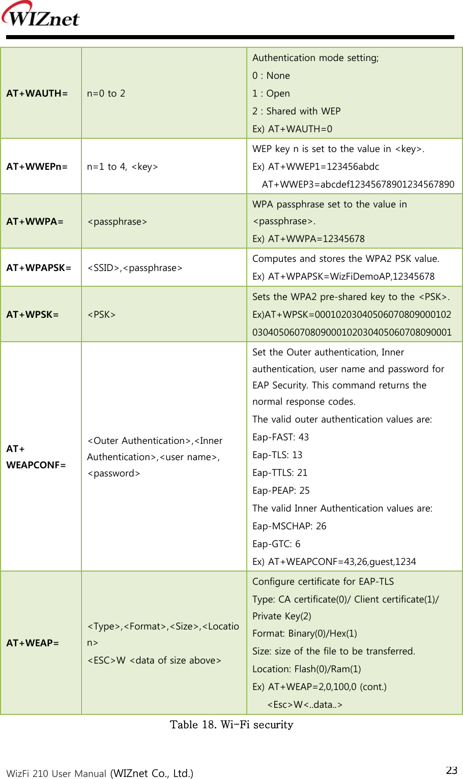
![WizFi 210 User Manual (WIZnet Co., Ltd.) 22(4) Wi-Fi interface Command Parameters Responses / Effects AT+NMAC=? Returns the current adapter MAC address. AT+NMAC2=? Returns the current adapter MAC address. AT+WREGDOMAIN= <Regulatory Domain> 0: FCC : supported Channel range is 1 to 11. 1: ETSI : supported Channel range is 1 to 13. 2: TELEC : supported Channel range is 1 to 14.Ex) AT+WREGDOMAIN=? AT+WREGDOMAIN=2 AT+WS= [<SSID>[,<BSSID>][,<Channel>][,<Scan Time>]] Network scan, returns list of found networks in the format: <SSID>,<BSSID>,<Channel>,<RSSI>,<Mode>,<Security> Ex) AT+WS AT+WS=,,6 AT+WM= n=0 (infrastructure) =1 (ad hoc) Set 802.11 Station operating mode. Ex) AT+WM=0 AT+WA= <SSID>[,[<BSSID>][,<Ch>]] Associate to specified SSID, BSSID, and channel. Ex)AT+WA=WizFiDemoAP AT+WD Disassociate from the current network. ATH Disassociate from the current network. AT+WWPS= <METHOD>[,PIN] Associate to an AP using WPS METHOD is push button (1) or pin (2). PIN is the pin for PIN method. AT+WWPS=2,12345670 AT+NSTAT=? Current wireless and network configuration. AT+WSTATUS Adapter reports the current network configuration to the serial host AT+WRSSI=? Current RSSI as ASCII. AT+WRATE=? Current transmit rate as ASCII. AT+WRETRY= <retrycount> Value of 802.11 TX retry is reset. Ex) AT+WRETRY=5 Table 17. Wi-Fi interface (5) Wi-Fi security Command Parameters Responses / Effects](https://usermanual.wiki/WIZNET/WIZFI220/User-Guide-1490506-Page-29.png)
![WizFi 210 User Manual (WIZnet Co., Ltd.) 24(6) Wireless configuration Command Parameters Responses / Effects AT+WRXACTIVE= n=0 (disable) =1 (enable) If 1, 802.11 radio is enabled. Ex) AT+WRXACTIVE=1 AT+WRXPS= n=0 (disable) =1 (enable) If 1, Power Save mode is enabled. Ex) AT+WRXPS=1 AT+MCSTSET= n=0 (disable) =1 (enable) If 1, multicast reception is enabled. AT+WP= <power> 8(Max) to 15(Min) Transmit power set to <power>. Ex) AT+WP=0 AT+WSYNCINTRL= <n> 1 to 65535. Configure the sync loss interval Ex) AT+WSYNCINTRL=30 AT+EXTPA= n=0 (disable) =1 (enable) Enable/disable the external PA Ex) AT+EXTPA=0 AT+PSPOLLINTRL= <n> 1 to 65535. Configure the keep-alive timer interval Ex) AT+PSPOLLINTRL=45 Table 19. Wireless configuration (7) Network interface Command Parameters Responses / Effects AT+NDHCP= n=0 (disable) =1 (enable) If 1, DHCP is enabled. AT+NSET= <Src Address>,<Net-mask>, <Gateway> Static network parameters; overrides previous values. Ex) AT+NSET=192.168.3.100,255.255.255.0,192.168.3.1 AT+DNSLOOKUP= <URL>,[<retry>,[<timeout=S>] Query DNS server for address of hostname URL. Ex) AT+DNSLOOKUP=google.com AT+DNSSET= <DNS1 IP>,[<DNS2 IP>] Set the DNS server addresses to be used. Ex) AT+DNSSET=192.168.3.1 AT+STORENWCONN Store network connection parameters prior to transition to Standby. AT+RESTORENWCONN Restore network connection parameters after wake from Standby. Table 20. Network interface](https://usermanual.wiki/WIZNET/WIZFI220/User-Guide-1490506-Page-31.png)
![WizFi 210 User Manual (WIZnet Co., Ltd.) 25(8) Connection management Command Parameters Responses / Effects AT+NCTCP= <Dest-Address>,<Port> Attempt TCP client connection to Destination; CONNECT <CID> if successful. Ex) AT+NCTCP=192.168.3.200,5000 AT+NCUDP= <Dest-Address>,<Port> [<,Src.Port>] Open UDP client socket to Destination; CONNECT <CID> if successful. Ex) AT+NCUDP=192.168.3.200,5000 AT+NSTCP= <Port> Start a TCP server on Port; CONNECT <CID> if successful. Ex) AT+NSTCP=5000 AT+NSUDP= <Port> UDP server on Port; CONNECT <CID> if successful. Ex) AT+NSUDP=5000 AT+CID=? Returns the current CID configuration. AT+NCLOSE= <CID> Close connection identified by CID. Ex) AT+NCLOSE=1 AT+NCLOSEALL Close all open connections. AT+SETSOCKOPT= <Cid>,<Type>,<Parameter>,<Value>,<Length> Configure a socket which is identified by a CidAT+SSLOPEN= <cid>,<certificate name> Open an SSL connection AT+SSLCLOSE= <cid> Close an SSL connection AT+HTTPCCONF= <Param>,<Value> Configure an HTTP client AT+HTTPCOPEN= <host>,<Port Number>, [<SSL Flag>,<certificate name>] Open an HTTP client connection. This command opens an HTTP client on the adaptor and connects to the server specified by the host name or IP address AT+HTTPCSEND= <cid>,<Type>,<Timeout>, <Page>,[Size of content] GET/POST HTTP data on the HTTP client connection AT+HTTPCCLOSE= <cid> Close the HTTP client connection AT+NRAW= <0|1|2> Enable / Disable Raw Ethernet support. AT+UNSOLICITEDTX= <Frame Control>,<Sequence Cntrl>,<Channel>,<Rate>,<WmmInfo>, <Receiver Mac>,<Bssid of Unsolicited data transmission](https://usermanual.wiki/WIZNET/WIZFI220/User-Guide-1490506-Page-32.png)
![WizFi 210 User Manual (WIZnet Co., Ltd.) 26AP>,<Frame Length> Table 21. Connection management (9) Battery check Command Parameters Responses / Effects AT+BCHKSTRT= <Batt.chk.freq> Start checking battery each 0 < Batt.chk.freq≤ 100 packets transmitted. AT+ BATTLVLSET= <Warning Level>,<Warning Freq>,<Standby Level> Set the battery warning/standby level to enable the adaptor’s internal battery measuring logic AT+BCHK= <Batt.chk.freq> Reset value of battery check frequency. AT+BCHKSTOP Stop checking battery. AT+BATTVALGET Retrieve the most recent battery check value. Table 22. Battery check (10) Power state management Command Parameters Responses / Effects AT+PSDPSLEEP Enable SOC Deep Sleep power saving mode. AT+PSSTBY= <x>[,<DelayTime>,<Alarm1 pol.>,<Alarm2 pol.>] Request transition to Standby for x milliseconds. Ex) AT+PSSTBY=60000,1000,1,1 AT+PSSTBY=5000 Table 23. Power state management (11) Auto connection Command Parameters Responses / Effects AT+WAUTO= <mode>,<SSID>,<BSSID>,[channel] Sets WiFi parameters to be used for Auto Connect. Mode is 0 for Infrastructure and 1 for Ad-hoc mode Ex) AT+WAUTO=0,WizFiDemoAP AT+NAUTO= <Type>,<Protocol>,<Destination IP>,<Destination Port> Sets network parameters to be used for Auto Connect. Type is 0 for Client and 1 for Server; Protocol is 0 for UDP and 1 for TCP;](https://usermanual.wiki/WIZNET/WIZFI220/User-Guide-1490506-Page-33.png)
![WizFi 210 User Manual (WIZnet Co., Ltd.) 27Ex) AT+NAUTO=0,1,192.168.3.101,5000 (TCP/Client) AT+NAUTO=1,1, ,5001 (TCP/Server) AT+NAUTO=0,0,192.168.3.101,5002 (UDP, Local/Remote Port is 5002) ATC n=0 (disable) =1 (enable) IF 1, Auto Connect is enabled on next reboot or AT. ATA Start Auto Connect, including association. ATA2 Start Auto Connect using existing association. ATO Return to a previous Auto Connect session; returns an error if no such session exists. Table 24. Auto connection (12) Provisioning Command Parameters Responses / Effects AT+WEBPROV= <user name>,<passwd> Provisioning through web pages AT+WEBLOGOADD= <size> maximum size is 1788 bytes Adding the Logo that will appear on the web pages used for provisioning. Table 25. Provisioning (13) Miscellaneous Command Parameters Responses / Effects AT+FWUP= <SrvIp>,<SrvPort>,<SrcPort>,[<retry>] Get a firmware upgrade from the server address/port to the adapter port SrcPort. Ex) AT+FWUP=192.168.3.200,667,667 AT+SETTIME= <dd/mm/yyyy>,<HH:MM:SS> Set the adaptor system time AT+ GETTIME=? Upon reception of this command the adaptor sends the current system time in milliseconds since epoch(1970) to the serial interface. The time format comes on the serial interface as follows: “Current Time in msec since epoch=xxxxxxx” AT+DGPIO= <GPIO-NO>,<SET/RESET(0/1)> Set or reset (high/low) a GPIO pin Ex) AT+DGPIO=31,0 AT+VER=? Return the current adapter firmware versions. AT+PING= <IP>,[[Trails],[<Interval>],[<Len>],[ PING the IP address provided. Trails = 0 will](https://usermanual.wiki/WIZNET/WIZFI220/User-Guide-1490506-Page-34.png)
![WizFi 210 User Manual (WIZnet Co., Ltd.) 28<TOS>],[<TTL>],[<PAYLOAD>]] ping until <Esc> C is issued. Ex) AT+PING=192.168.3.1,5 AT+TRACEROUTE= <IP>,[[Interval],[<MaxHops>],[<MinHops>],[<TOS>]] Trace the route to the IP address provided. Ex) AT+TRACEROUTE=74.125.155.103 AT+XDUM= n=1 (disable) =0 (enable) If 1, UART Message is Disabled.(When Auto Connection Mode) AT+XEHT= n=0 (disable) =1 (enable) If 1, Hardware Trigger is Enabled. Table 26. Miscellaneous](https://usermanual.wiki/WIZNET/WIZFI220/User-Guide-1490506-Page-35.png)