WIZNET WIZFI630A WiFi Module User Manual
WIZNET Co., LTD. WiFi Module
UserManual.wiki
>
WIZNET
>
WIZFI630A User Manual
User Manual
Navigation menu
Upload a User Manual
Namespaces
Wiki Guide
HTML
PDF
Info
Views
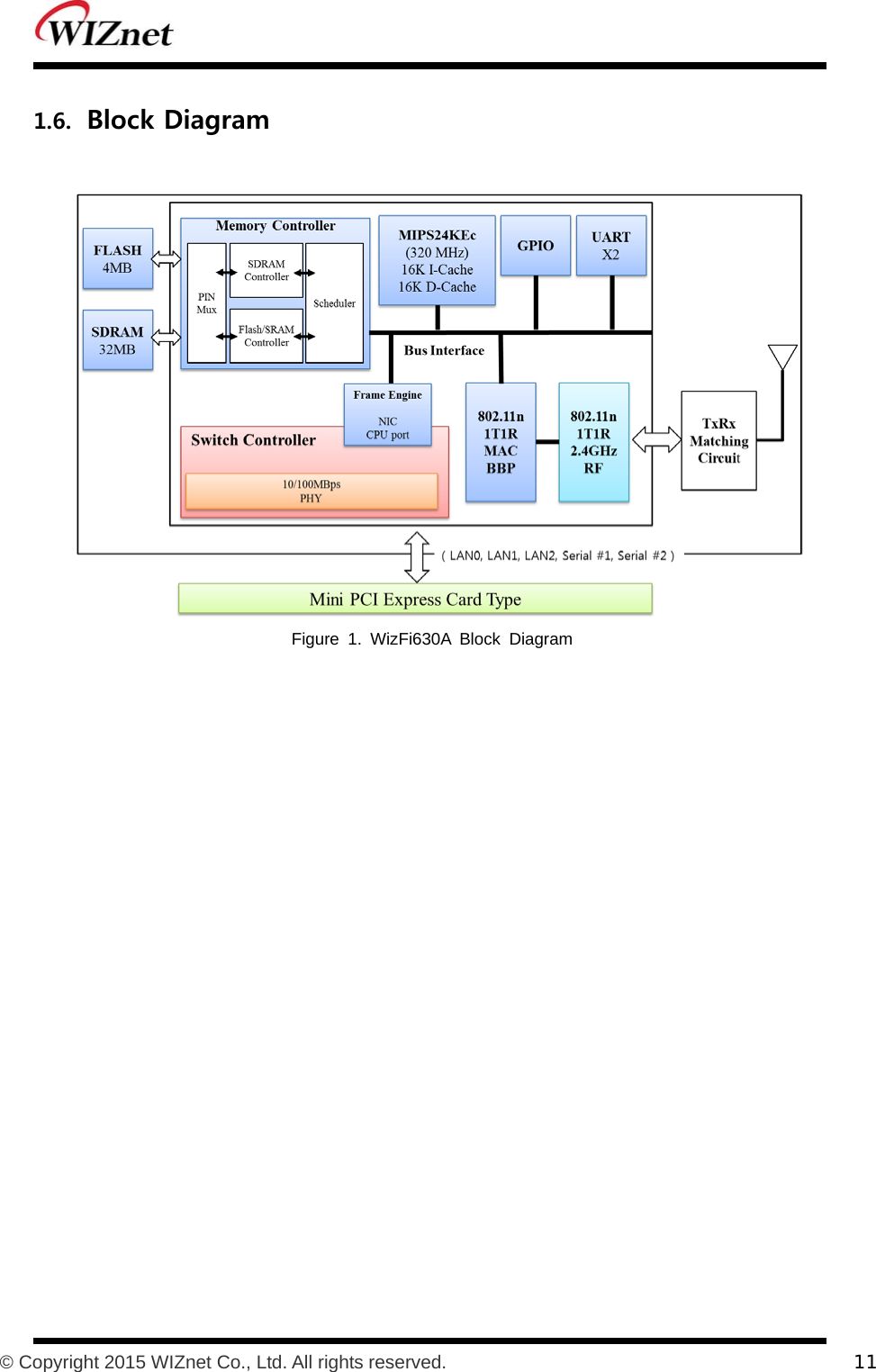
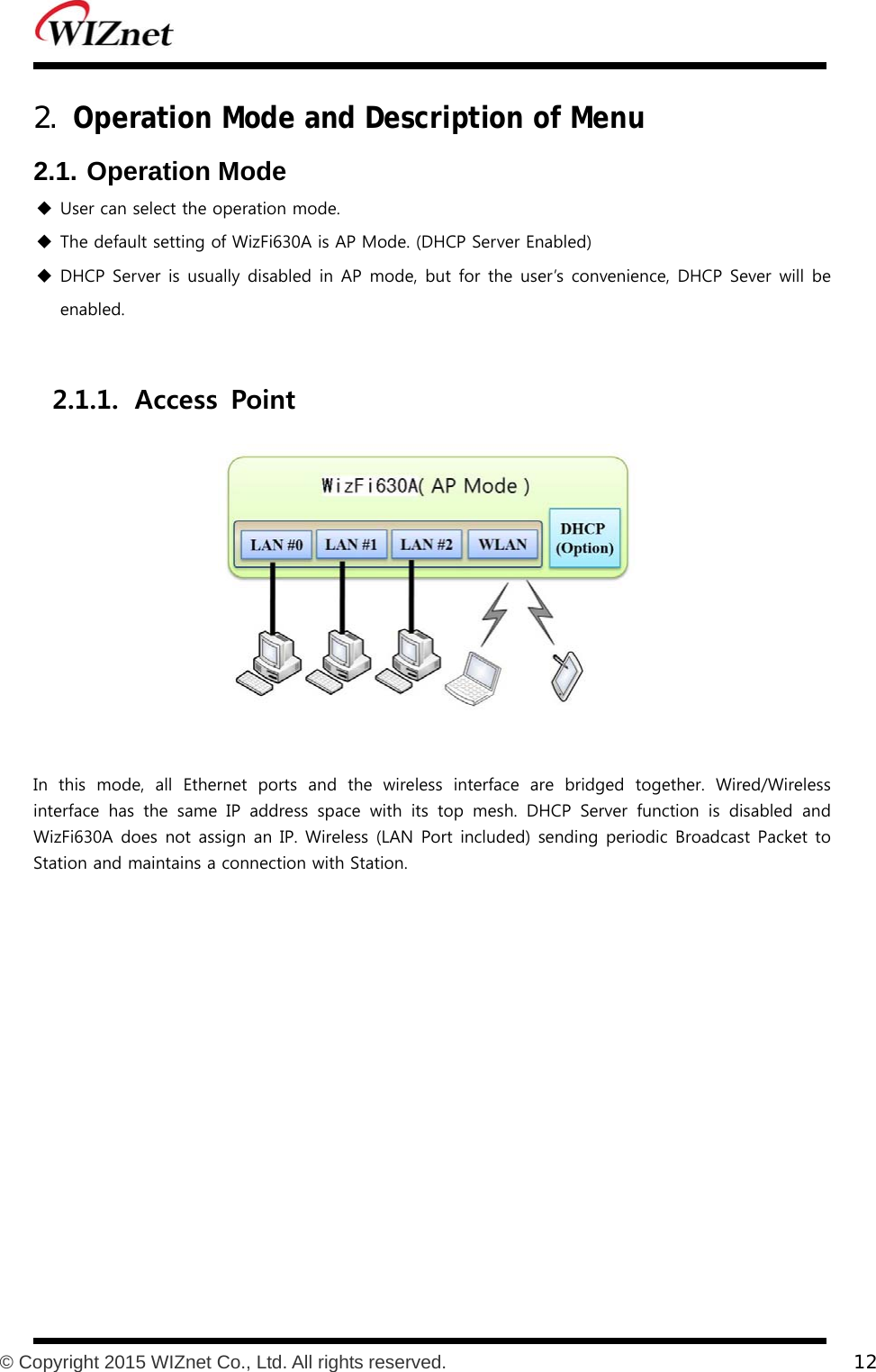
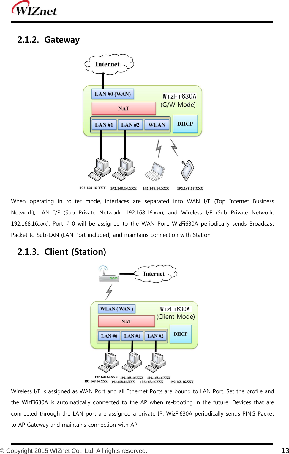
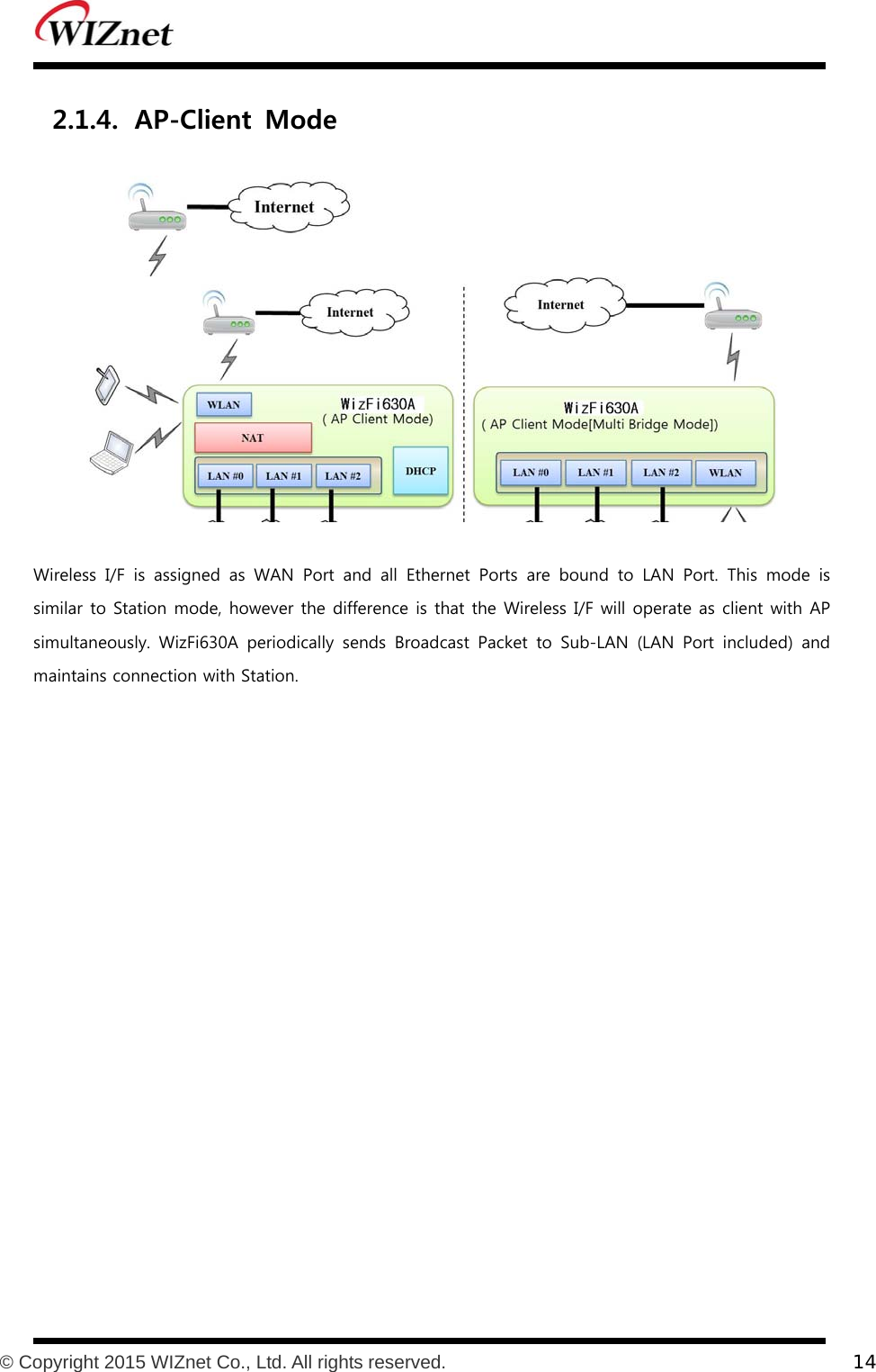
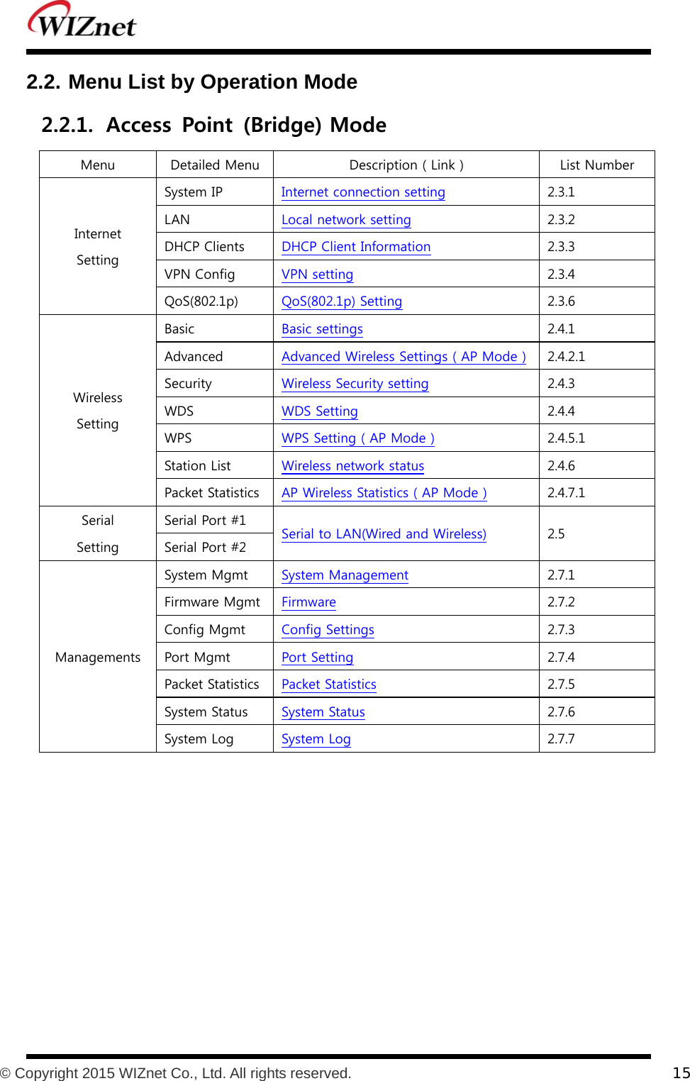
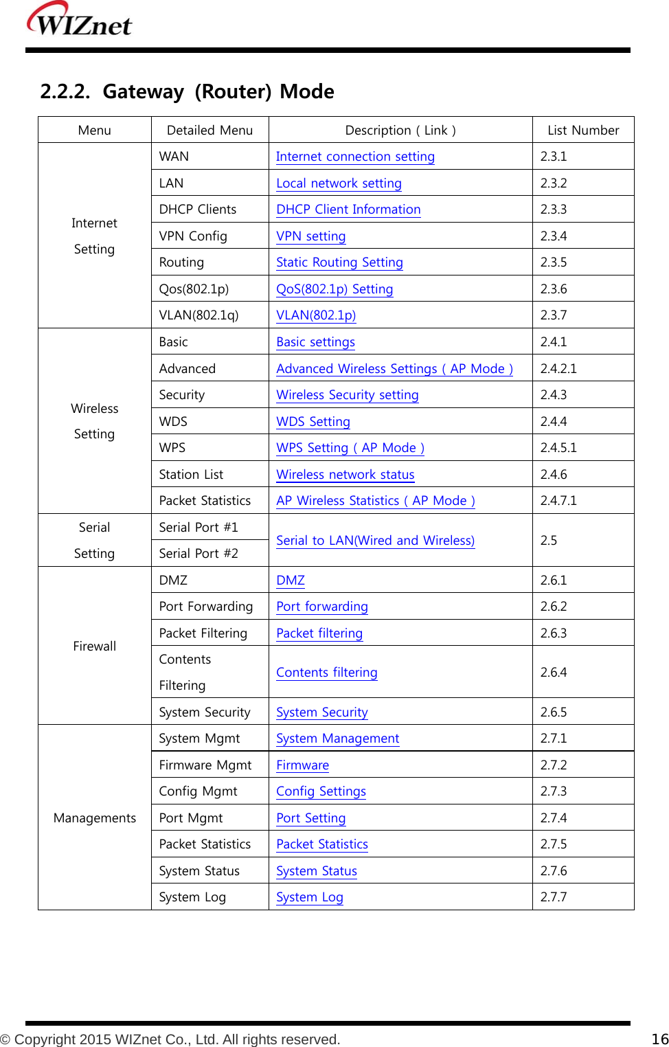
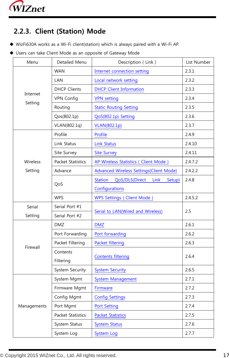
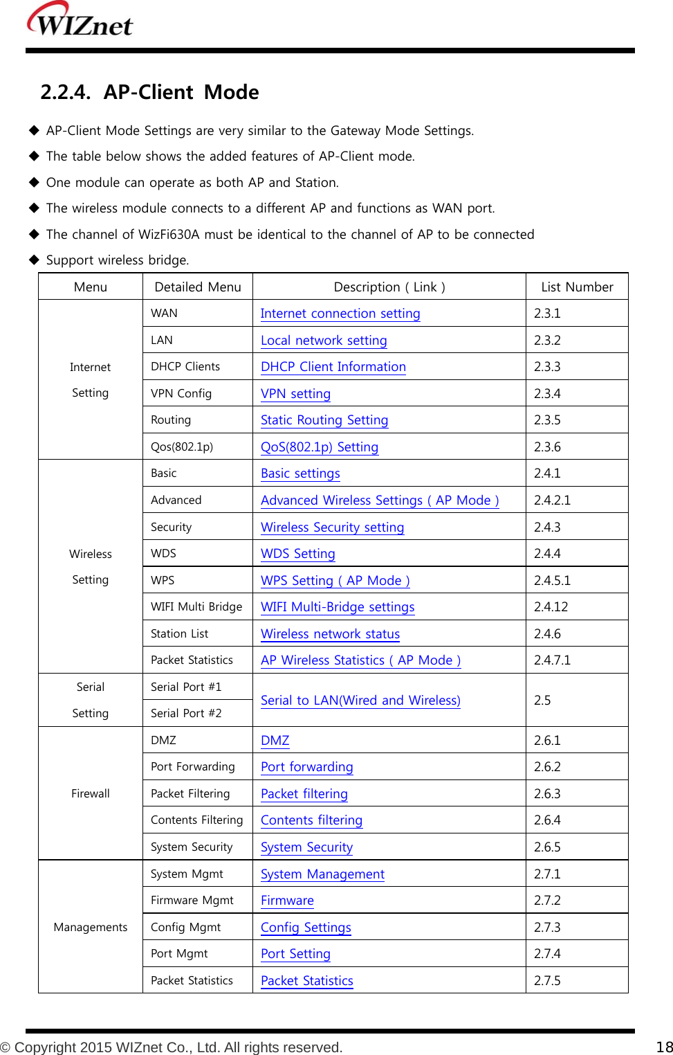
User Manual
Discussion / Help
Navigation
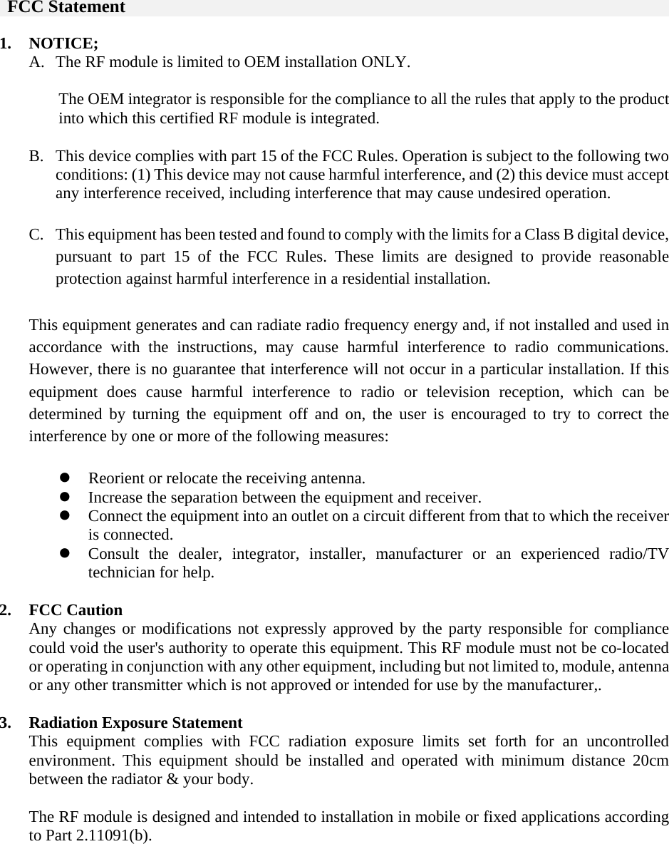
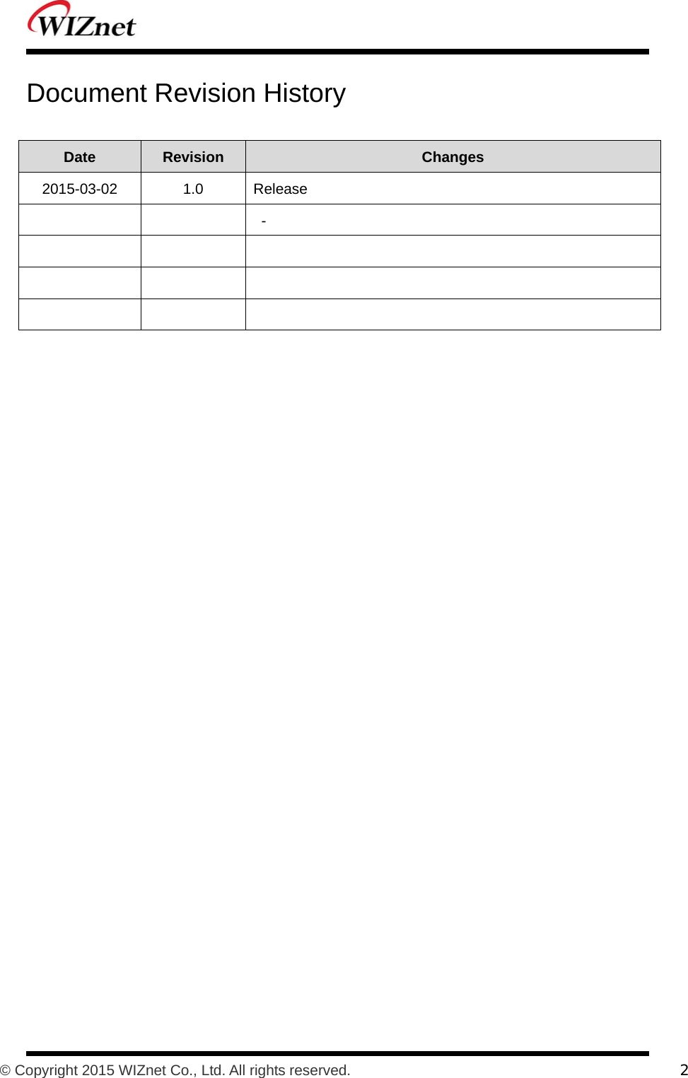
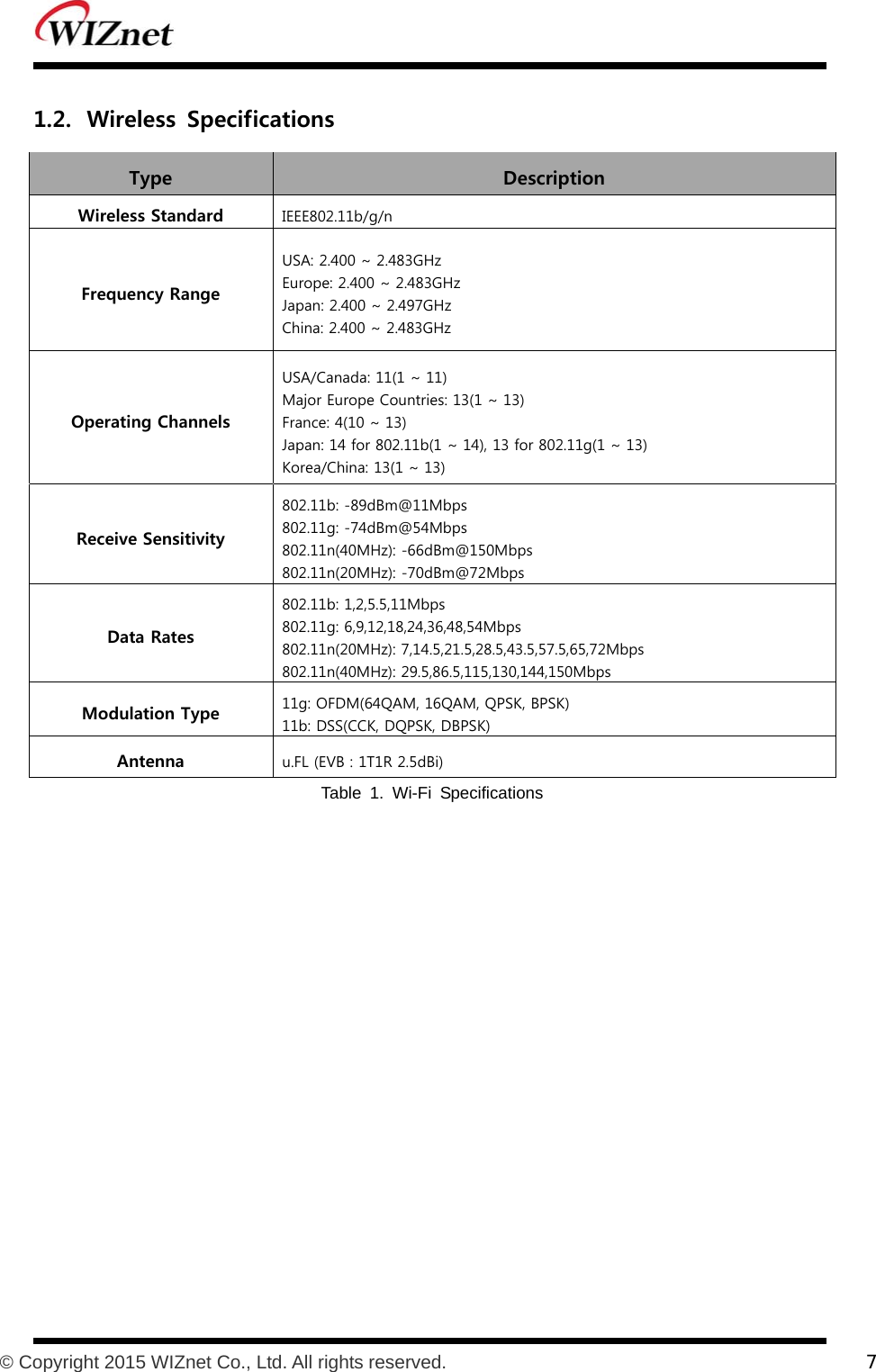
![4. This device is intended only for OEM integrators under the following conditions: The antenna must be installed such that minimum 20 cm is maintained between the antenna and users, and the RF module may not be co-located with any other transmitter or antenna. As long as 2 conditions above are met, further transmitter test will not be required. However, the OEM integrator is still responsible for testing their end-product for any additional compliance requirements required with this module installed. 5. IMPORTANT NOTE: In the event that these conditions cannot be met, then the FCC authorization is no longer considered valid and the FCC ID cannot be used on the final product. In these circumstances, the OEM integrator will be responsible for re-evaluating the end product (including the transmitter) and obtaining a separate FCC authorization. 6. End Product Labeling This RFID Reader module is authorized only for use in device where the antenna may be installed such that minimum 20 cm may be maintained between the antenna and users. The final end product must be labeled in a visible area with the following: “Contains FCC ID: XR2WIZFI630A”. The grantee's FCC ID can be used only when all FCC/ IC compliance requirements are met. 7. Guidance to the Host Manufacturer The host manufacturer is responsible for ensuring that after the module is installed and operational the host manufacturer continues to be compliant with the Part 15B unintentional radiator requirements. Since this may depend on the details of how the module is integrated with the host, the grantee (the party responsible for the module grant) shall provide guidance to the host manufacturer for compliance with the Part 15B requirement. 8. Manual Information To the End User The OEM integrator has to be aware not to provide information to the end user regarding how to install or remove this RF module in the user's manual of the end product which integrates this module. The end user manual shall include all required regulatory information/warning as show in this manual. 9. Antenna List No. Model Type Gain[dBi] Impedance 1 W5I–BO-07-F245 UFL type antenna 2.5 50](https://usermanual.wiki/WIZNET/WIZFI630A/User-Guide-2849469-Page-3.png)