WJ Communications WJMPR6XXX RFID Reader User Manual
WJ Communications, Inc. RFID Reader
UserManual.wiki
>
WJ Communications
>
WJMPR6XXX User Manual
User Manual
Navigation menu
Upload a User Manual
Namespaces
Wiki Guide
HTML
PDF
Info
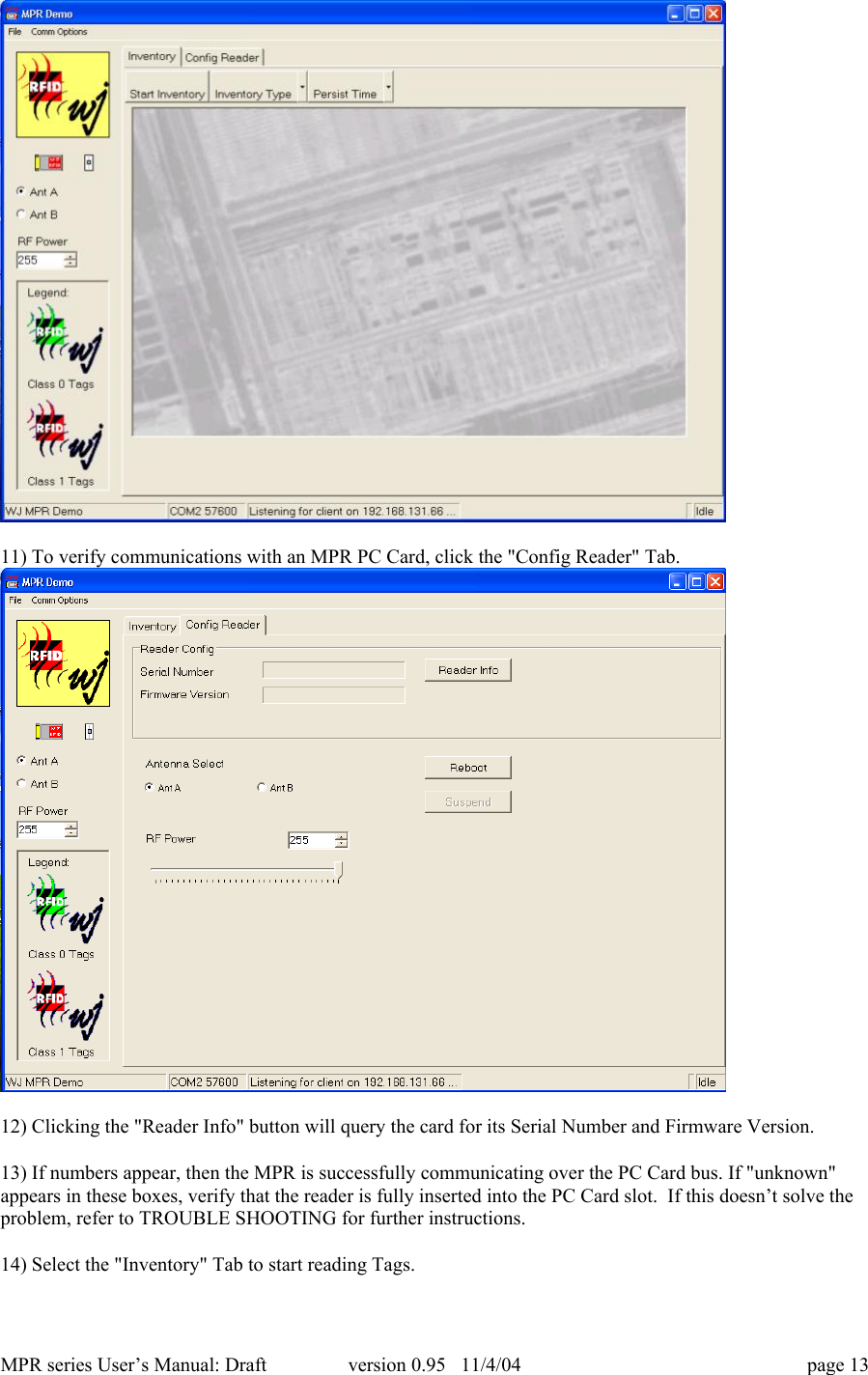
Views
User Manual
Discussion / Help
Navigation
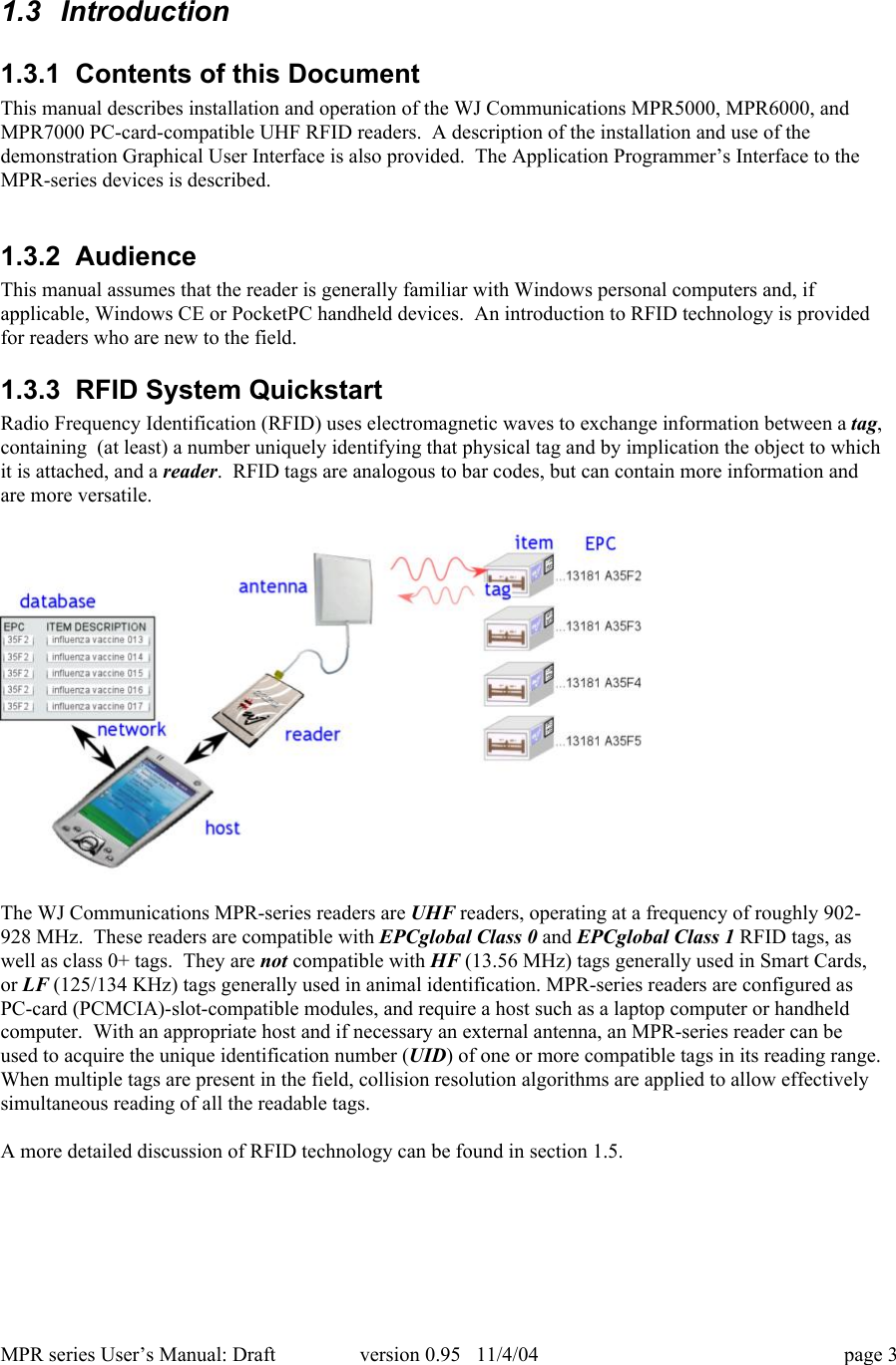
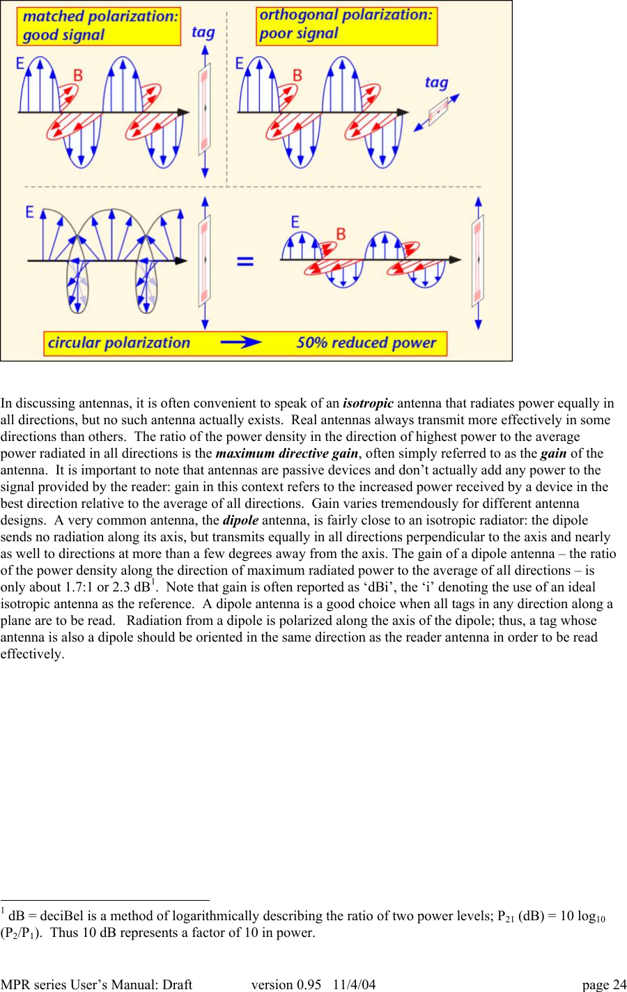
![MPR series User’s Manual: Draft version 0.95 11/4/04 page 22be simultaneously present in the field of the reader and read ‘simultaneously’ from the viewpointof the user. RFID techniques permit automated information handling to a much greater extentthan bar codes.• ROBUSTNESS: Bar codes cannot be read if the printed code becomes dirty, defaced, orexcessively bent or curled. RFID tags are robust to dirt, paint, ink, and to some extent mechanicaldamage, and can be read (albeit with reduced range) when misoriented or mechanically distorted.RFID tags are tougher than bar codes.1.5.3 RFID system componentsAn RFID system is composed of (at least) a reader, one or more antennas, and one or more compatibletags. In many applications it may be necessary or helpful to create human-readable labels incorporatingRFID tags; in this case an RFID tag printer is also very useful. While standalone RFID systems areappropriate in some circumstances, more commonly the RFID reader is just a sensor that needs to interactwith a larger information system in order to be useful. Middleware is used to enable the interactionbetween the reader and the network, and to filter and aggregate the large amounts of data the reader collectsinto a more useful compendium provided to the network.1.5.3.1 ReaderA UHF RFID reader is a radio transmitter and receiver. Most readers are capable of interrogating passivetags, and are equipped with certain features uniquely suited to use for communicating with passive RFIDtags. A reader reading passive tags simultaneously communicates with the tag population and providespower to operate the integrated circuits contained in the tags. During transmission, the reader transmits anamplitude-modulated signal that is received by tags within range. The transmit power is generally limitedby regulatory requirements; for example, in the United States, no more than 1 watt average RF power maybe transmitted. Modulation rate varies depending on the standard employed, but is typically a few tens ofkilobits per second for UHF tags. Special coding of the transmitted data is employed to maximize thepower available to the tags.Once the tags have been powered up and received their instructions from the reader, they take turnsresponding with their UID. Because of the unique requirements of the backscatter radio system used bypassive and semi-passive tags, the reader must continue to transmit a non-modulated (continuous-wave orCW) signal while it listens for tag responses. The tags employ the CW signal to continue to provide powerto the tag electronics, and modulate the impedance of their own antennas in order to vary the signalreflected back to the reader. The reader must extract the very small tag reflections from all the otherreflected signals it encounters. The MPR-series cards use one antenna for both transmit and receivefunctions. [ MPR6000 and MPR7000 readers have two external antenna connectors. However, only oneantenna is in use at any given time, for both transmit and receive. The reader can switch from one antennato the other in order to cover differing physical regions, such as the high and low portions of a doorway, orto avoid missing tags because of local losses of signal strength – fading – that are sensitive to the exactposition of the antenna and other objects.] Even with a well-matched antenna, the reflection from theantenna back to the reader is much larger than any other reflected signal, and represents the main obstacleto receiving the tag reflection. Degraded antenna match will lead to an increased antenna reflection,making it harder for the reader to extract the tag signal and thus reducing read range. The antenna match issensitive to the immediate antenna environment (objects within a few cm of the antenna). For best results,antennas should always be mounted in accordance with manufacturer’s recommendations, and free ofobstructions for at least 50 cm (20 inches) in the read direction.In the United States, readers are required by law to hop randomly from one frequency channel to anotherwhen operating within the ISM band, residing for no longer than 0.4 seconds at any one frequency. Inaddition, regulations forbid coordination of hopping patterns between collocated transmitters. Whenconfigured for US operation, the MPR series uses 50 channels separated from one another by 500 KHz, and](https://usermanual.wiki/WJ-Communications/WJMPR6XXX/User-Guide-495821-Page-22.png)
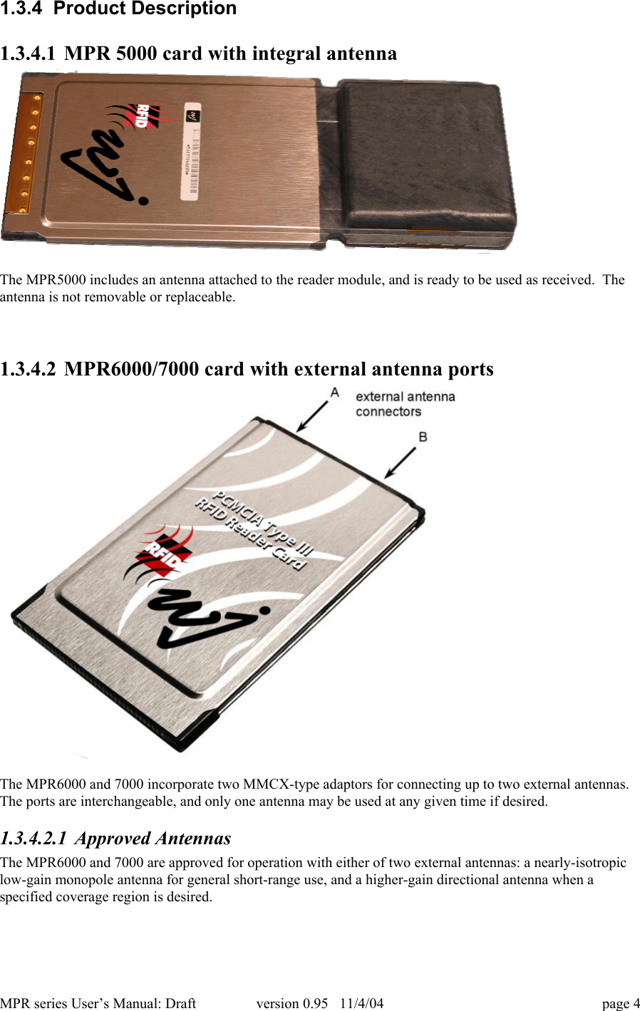
![MPR series User’s Manual: Draft version 0.95 11/4/04 page 25The MPR5000 integral antenna behaves like a dipole oriented parallel to the short edge of the card. Thus,radiation is mainly forward (looking along the long axis of the card), up, and down, but with very littlepower radiated to the left or right of the card. The radiation pattern can be regarded as a torus (doughnut)with axis along the short side of the card.The recommended isotropic antenna for the MPR6000/7000, the MAXRAD [model number for PN1789] isa monopole antenna, essentially a half of a dipole antenna placed above a conductive ground plane. Theground plane acts to create a reflected image of the monopole; the monopole and its image together form adipole antenna. Thus for directions above the ground plane, the radiation of the monopole resembles thatof a dipole, but for sufficiently large ground planes there is very little radiation below the ground plane.The ground plane should be at least 2-3 wavelengths across (about 60 cm or 25 inches on a side at 900MHz) to ensure minimal bottom-side radiation. Monopole antennas are compact and easy to use, andappropriate when one wishes to find tags located in any direction around the monopole axis.PATTERN IF AVAILABLERelatively isotropic antennas are easy to use, but if tags are expected to be found mainly in one directionwith respect to the antenna, radiation in the other directions is wasted. In such circumstances, an antennawith higher gain – a directional antenna – will provide better read range. A common type of directional](https://usermanual.wiki/WJ-Communications/WJMPR6XXX/User-Guide-495821-Page-25.png)
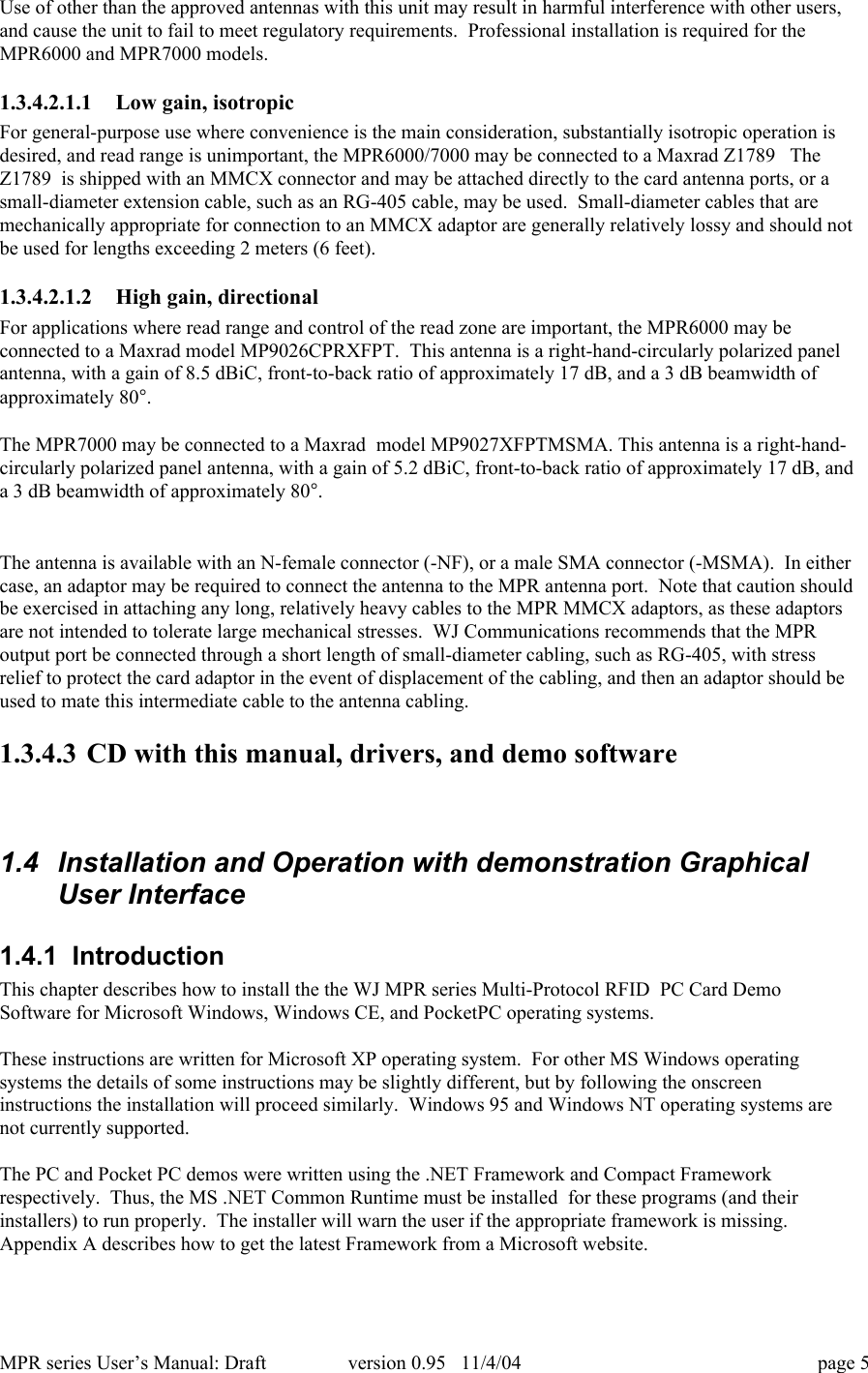
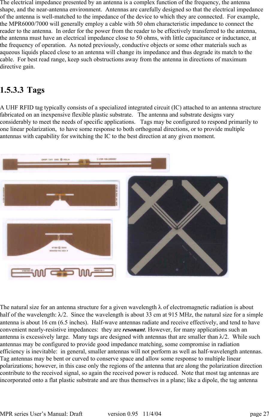
![MPR series User’s Manual: Draft version 0.95 11/4/04 page 26antenna is the patch antenna (also known as a microstrip or panel antenna). Patch antennas aremanufactured using techniques similar to those used to make printed circuits, and are inexpensive androbust. They use a metal ground plane above which are printed resonant metal blocks; as a consequencethey are generally flat and radiate primarily in the direction opposite the ground plane. Most commercialpatch antennas are packaged inside a plastic radome to provide mechanical protection and a more pleasingappearance.The recommended directional antenna for the MPR6000/7000, the Maxrad MP9026CPR, is a patchantenna, with about 8.5 dBiC of gain in the direction perpendicular to the rounded face of the radome.(The notation ‘dBiC’ indicates that the gain is that which would be measured using a circularly polarizedreceiving antenna; a linearly polarized received would find 3 dB less power in the direction of maximumgain.) Patch antennas can be linearly or circularly polarized. The MP9026CPR is circularly polarized.As discussed above, circular polarization is a good choice when the tag orientation is not known. Thepatch antenna, being of higher gain, will provide a significant improvement in read range over themonopole antenna. Shown below is the radiation pattern of this antenna along the azimuth (horizontalplane for a typical vertically-mounted antenna).In principle, antenna gain could be increased to increase read range. However, in most jurisdictions, themaximum gain employed in unlicensed operation is limited by regulation. For example, in the UnitedStates, the FCC limits the effective isotropic radiated power (EIRP, the product of the actual power and theantenna gain) to 4 watts. For the MPR6000, which is rated at _ watt output, the highest antenna gainlegally allowed is a factor of 8 (9 dB) relative to an isotropic antenna. The MPR7000, which is rated at 1Watt output, cannot use an antenna with more than 6 dBi of gain.Note that the recommended antennas have been specifically approved for use with the MPR6000/7000 inthe United States by the FCC [pending at time of writing]. FCC regulations (title 47 part 15) require thatantennas be approved for use with specific radio communications devices, unless they are installed by aprofessional installer, and that in all cases the combination of antenna and radio device must operate withinregulatory constraints.External antennas are generally connected to the reader using flexible coaxial cables and connectors. It isimportant to select these cables and connectors appropriately for the application. The MPR6000 andMPR7000 use MMCX connectors, which are very small and convenient for the limited form factor of aPC-card slot. However, MMCX connectors must be protected from mechanical stress. This can be doneby using fine-diameter cabling, such as RG-405, to make the connections to the card. However, such cablehas relatively high losses, and should not be used for runs longer than about 2 meters (6 feet). When theantenna must be mounted a long distance from the cable, an adaptor should be used at the end of a short runof small-diameter cable to connect to a larger cable, such as RG-213 or RG214, using an adaptor to therelevant connector, which may be an SMA or N-type connector.](https://usermanual.wiki/WJ-Communications/WJMPR6XXX/User-Guide-495821-Page-26.png)
![MPR series User’s Manual: Draft version 0.95 11/4/04 page 32Each time power is turned on, the reader proceeds through a set of steps to initialize the tag IC timing.First, the reader transmits a RESET consisting of 800 ms of CW power. A tag’s “ID’d” flag (telling it thatit was already read by the reader) may survive a RESET, but in other respects the tag returns to its defaultstate. After the RESET, 8 pulses are used to calibrate the tag internal oscillator to the 2.2 MHz sub-carrierfrequency. Finally, a set of pulses of varying length is transmitted to set the thresholds for distinguishingbetween 0, 1, and null, and to signal the tag when to begin its transmission.In the United States, communications devices operating in unlicensed bands must either use direct-sequence or frequency-hopping spreading techniques. The MPR series products use pseudo-randomhopping from one frequency to another. The Class 0 protocol does not require the reader to power downduring hops, but the MPR5000 does in order to minimize spurious radiation. Therefore, a RESET /calibration sequence is necessary after each hop. The time between hops is available for the user to adjust,although regulations require that the transmitter remain on any given frequency for no longer than 400 msat a time. In Europe, revised regulations allowing 10 channels have been promulgated and it is anticipatedthat with the passing of time frequency-hopping operation will become the normal means of operation inmost European jurisdictions. European regulations will require that the reader listen before talking: that is,the reader must check each putative channel for other active transmitters before beginning its owntransmission. Note that the MPR5000/6000/7000 operate at 902-928 MHz and are not approved for use inRegion 1 (European) jurisdictions.Tags have 10 possible states, roughly corresponding to [startup / calibrate], [global commands], [binary treetraversal], and [singulated commands]. Each command is 8 bits long, with an additional parity bit providedfor error checking. The tag echoes each bit it receives in order to provide a simple error check andacknowledgement function. Mandatory commands are:• ResetIDFlag: resets the identified flag to NOT READ; that is, it forces tags to forget whether theyhave been previously inventoried.• SetNegotiationPage: this curious terminology is used to describe the choice of ID (ID0, 1, or 2)used for singulation during binary tree traversal.• SegRegionofOperation: sets the backscatter parameters according to whether the device isoperating under FCC or European regulations.• ForceDormant: tags receiving this command immediately enter the Dormant state. The Dormantstate is the default tag turn-on state, exited when a RESET is received.• ForceMute: tags receiving this command immediately enter the Mute state. In the Mute state, thetags receive data but do not respond until a NULL is received. Tags that have been bypassedduring traversal reside in the Mute state until the next traversal begins.• Read: Read ID1 or ID2 (ID0, being randomly generated at the time of request, has no enduringinterest and need not be read from the tag).• Kill: Permanently disables the tag if a valid argument (passcode) is provided.1.5.4.1.2 EPC Class 1 Summary](https://usermanual.wiki/WJ-Communications/WJMPR6XXX/User-Guide-495821-Page-32.png)
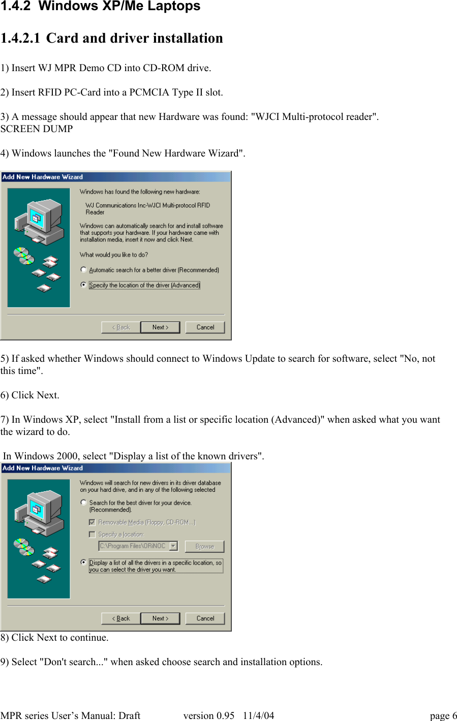
![MPR series User’s Manual: Draft version 0.95 11/4/04 page 381.6.6.3 CRC CalculationA 16bit CCITT CRC is used for error detection and placed at the end of the frame. The calculation uses allbytes of the frame excluding the leading SOF. The CCITT CRC polynomial is x16 + x12 + x5 + 1, and thepreload value is 0xFFFF. The CRC is appended to the frame after the command data, MSB first. Thefollowing code snippet and test vectors can be used as a guide to implement the CRC. The bitwiseinversion (CRC XOR 0xFF) of the CRC is included in a transmitted frame. On receipt, the CRC iscomputed on the bytes between SOF and CRC. For valid frames, this will agree with the transmitted CRCvalue.Some Test Vectors:"ABCDEFG" returns 0xB82F"WJCI RFID" returns 0x9ACFAn array of 256 capital 'N' characters returns 0xE45C/*This calculation uses a table lookup to generate CCITT CRC values.The CCITT polynomial is: x^16 + x^12 + x^5 + 1Forward direction table - i.e. msbit first*/static unsigned int crctab[256] = {0x0000, 0x1021, 0x2042, 0x3063, 0x4084, 0x50A5, 0x60C6, 0x70E7, 0x8108,0x9129, 0xA14A, 0xB16B, 0xC18C, 0xD1AD, 0xE1CE, 0xF1EF, 0x1231, 0x0210,0x3273, 0x2252, 0x52B5, 0x4294, 0x72F7, 0x62D6, 0x9339, 0x8318, 0xB37B,0xA35A, 0xD3BD, 0xC39C, 0xF3FF, 0xE3DE, 0x2462, 0x3443, 0x0420, 0x1401,0x64E6, 0x74C7, 0x44A4, 0x5485, 0xA56A, 0xB54B, 0x8528, 0x9509, 0xE5EE,0xF5CF, 0xC5AC, 0xD58D, 0x3653, 0x2672, 0x1611, 0x0630, 0x76D7, 0x66F6,0x5695, 0x46B4, 0xB75B, 0xA77A, 0x9719, 0x8738, 0xF7DF, 0xE7FE, 0xD79D,0xC7BC, 0x48C4, 0x58E5, 0x6886, 0x78A7, 0x0840, 0x1861, 0x2802, 0x3823,0xC9CC, 0xD9ED, 0xE98E, 0xF9AF, 0x8948, 0x9969, 0xA90A, 0xB92B, 0x5AF5,0x4AD4, 0x7AB7, 0x6A96, 0x1A71, 0x0A50, 0x3A33, 0x2A12, 0xDBFD, 0xCBDC,0xFBBF, 0xEB9E, 0x9B79, 0x8B58, 0xBB3B, 0xAB1A, 0x6CA6, 0x7C87, 0x4CE4,0x5CC5, 0x2C22, 0x3C03, 0x0C60, 0x1C41, 0xEDAE, 0xFD8F, 0xCDEC, 0xDDCD,0xAD2A, 0xBD0B, 0x8D68, 0x9D49, 0x7E97, 0x6EB6, 0x5ED5, 0x4EF4, 0x3E13,0x2E32, 0x1E51, 0x0E70, 0xFF9F, 0xEFBE, 0xDFDD, 0xCFFC, 0xBF1B, 0xAF3A,0x9F59, 0x8F78, 0x9188, 0x81A9, 0xB1CA, 0xA1EB, 0xD10C, 0xC12D, 0xF14E,0xE16F, 0x1080, 0x00A1, 0x30C2, 0x20E3, 0x5004, 0x4025, 0x7046, 0x6067,0x83B9, 0x9398, 0xA3FB, 0xB3DA, 0xC33D, 0xD31C, 0xE37F, 0xF35E, 0x02B1,0x1290, 0x22F3, 0x32D2, 0x4235, 0x5214, 0x6277, 0x7256, 0xB5EA, 0xA5CB,0x95A8, 0x8589, 0xF56E, 0xE54F, 0xD52C, 0xC50D, 0x34E2, 0x24C3, 0x14A0,0x0481, 0x7466, 0x6447, 0x5424, 0x4405, 0xA7DB, 0xB7FA, 0x8799, 0x97B8,0xE75F, 0xF77E, 0xC71D, 0xD73C, 0x26D3, 0x36F2, 0x0691, 0x16B0, 0x6657,0x7676, 0x4615, 0x5634, 0xD94C, 0xC96D, 0xF90E, 0xE92F, 0x99C8, 0x89E9,0xB98A, 0xA9AB, 0x5844, 0x4865, 0x7806, 0x6827, 0x18C0, 0x08E1, 0x3882,0x28A3, 0xCB7D, 0xDB5C, 0xEB3F, 0xFB1E, 0x8BF9, 0x9BD8, 0xABBB, 0xBB9A,0x4A75, 0x5A54, 0x6A37, 0x7A16, 0x0AF1, 0x1AD0, 0x2AB3, 0x3A92, 0xFD2E,0xED0F, 0xDD6C, 0xCD4D, 0xBDAA, 0xAD8B, 0x9DE8, 0x8DC9, 0x7C26, 0x6C07,0x5C64, 0x4C45, 0x3CA2, 0x2C83, 0x1CE0, 0x0CC1, 0xEF1F, 0xFF3E, 0xCF5D,0xDF7C, 0xAF9B, 0xBFBA, 0x8FD9, 0x9FF8, 0x6E17, 0x7E36, 0x4E55, 0x5E74,0x2E93, 0x3EB2, 0x0ED1, 0x1EF0](https://usermanual.wiki/WJ-Communications/WJMPR6XXX/User-Guide-495821-Page-38.png)
![MPR series User’s Manual: Draft version 0.95 11/4/04 page 39};unsigned short CalculateBlockCRC16(byte count, char *buffer){unsigned short crc = 0xFFFF;char *pBuf;pBuf = (char *)buffer;while (count--)crc = (unsigned short)((crc << 8) ^ crctab[(crc >> 8) ^*pBuf++]);return (unsigned short)(~crc);}](https://usermanual.wiki/WJ-Communications/WJMPR6XXX/User-Guide-495821-Page-39.png)