WOORIRO WDR210 24GHz Smart Radar User Manual Technical R2
WOORIRO CO., LTD. 24GHz Smart Radar Technical R2
WOORIRO >
Technical-User Manual_R2.pdf
CONFIDENTIAL AND PROPRIETARY
The information contained in this document shall remain the sole and exclusive property of Wooriro Co., LTD and shall not
be disclosed by the recipient to third parties without prior consent of Wooriro in writing.
Operation Manual (Model:WDR210)
Ver. 1.0 – 08/29/2017
1
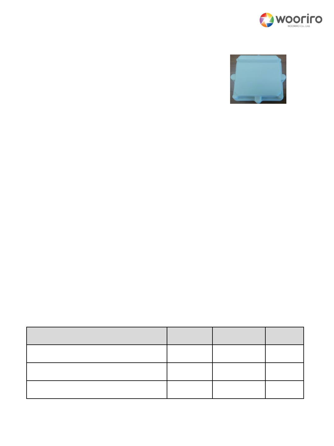
1. Features and Applications
This radar(Model: WDR210) operating at 24GHz ISM band, is released to
be used for 2D position and movement detection.
For vehicles it detects up to 50 m, which is robust to the environmental
change such as light, ambient temperature, dust etc.
User friendly designs such as small form factor and wired/wireless
communication interfaces provides easy application of this device.
In addition to 2D information of targets, it adopts a tracking algorithm to
differentiate motions between natural and artificial motion, resulting in very
low false alarms. This enables WDR210 good enough for the outdoor
applications.
The sensor is suitable for the energy saving application by motion
detection.
2. Maximum Ratings
Parameter
Symbol
Rating
Unit
Supplied voltage
VDC
+12
VDC
Operating temperature range
TC
-40 to +85
℃
Storage temperature range
TSTG
-50 to +130
℃

CONFIDENTIAL AND PROPRIETARY
The information contained in this document shall remain the sole and exclusive property of Wooriro Co., LTD and shall not
be disclosed by the recipient to third parties without prior consent of Wooriro in writing.
2
3. Performance Characteristics
Parameter
Performance
Condition
Tx Frequency
24GHz ISM band
24.05~24.25GHz
(EU/South Korea)
24.05~24.25 GHz
(North America)
Output EIRP
18dBm max
adjustable
Detection
Range
30m/60m max
Human Body/Vehicles
Range
resolution
75cm
60cm
EU/South Korea
North America
Angle
150 o / 60 o
Type A/Type B; horizontal
Angle
Resolution
+/- 5o max
Data Update
7Hz max
Size
108X118.2X36.4 mm3
Interface
UART
Opt.: CAN2.0 or RS485
Supply voltage
+12VDC
Power Consumption
2W max

CONFIDENTIAL AND PROPRIETARY
The information contained in this document shall remain the sole and exclusive property of Wooriro Co., LTD and shall not
be disclosed by the recipient to third parties without prior consent of Wooriro in writing.
Outline Dimensions (mm)
3
Top View
Side View
Bottom View

CONFIDENTIAL AND PROPRIETARY
The information contained in this document shall remain the sole and exclusive property of Wooriro Co., LTD and shall not
be disclosed by the recipient to third parties without prior consent of Wooriro in writing.
4
5. Set Functions
5.1. 2MT3005-X08200 Connector Pin Configuration
Type
Pin#
Function
Description
Wire Color
M12, 8pin
1
VDC
+12VDC Input
Block
2
GND
Ground
Brown
3
RS485-B
CAN H or UART_TX(opt.)
Green
4
RS485-A
CAN L or UART_RX(opt.)
Yellow
5
NC
Internal Use Only
Grey
6
NC
Internal Use Only
White
7
NC
Internal Use Only
Blue
8
GPIO
3.3V Digital Output
(“H” for detection)
Red
5.2. Serial Communication
CONFIDENTIAL AND PROPRIETARY
The information contained in this document shall remain the sole and exclusive property of Wooriro Co., LTD and shall not
be disclosed by the recipient to third parties without prior consent of Wooriro in writing.
5.3.1. MasterWDR210 (2-byte)
5
Baud rate = 115200bps, Parity = none, Data bits = 8bit, Stop = 1bit
(UART/CAN2.0/RS485)
* Default setting(can be changed according to application region)
Note : No change occurs when out of range data is received
Function
DATA(MSB - LSB)
Note
Set Tx
Power
0X5A5A
(RS485)
0X01
0X{value}
{value}= 0*~7, 0 max, 1dB power
decrease per 1 increase
Set Tx
Ramp Type
0X02
0X{value}
{value} =1*~5
(See description below)
Tx Off
0X03
0X{value}
{value} = 1 Tx Off
otherwise Tx On
Raw Data/
Report
Detection/
Report
Setting
Values
0X04
0X{value}
{value} = 01
Raw data
{value} =02*
Report
Detection(short)
{value} =03
Report
Detection(long)
{value} =04
Report Setting
Values
All are one-time report except
“Report detection” (continuous
report)

CONFIDENTIAL AND PROPRIETARY
The information contained in this document shall remain the sole and exclusive property of Wooriro Co., LTD and shall not
be disclosed by the recipient to third parties without prior consent of Wooriro in writing.
6
f_Tx
t
…. ….
T_up T_dn
T_ramp=T_up+T_dn
f
5.3.2. WDR210Master
See AN210-1 for the details of “Raw Data/Report Detection/Report
Setting Values”
Fct.
MSB
byte
LSB
byte
T_up [us]
T_dn [us]
f [MHz]
Set Tx
Ramp
Type
0X02
1
60
15
75 (80)
2
200 (140)
3
200 (145)
4*
200 (148)
5
250 (195)
WDR210
CONFIDENTIAL AND PROPRIETARY
The information contained in this document shall remain the sole and exclusive property of Wooriro Co., LTD and shall not
be disclosed by the recipient to third parties without prior consent of Wooriro in writing.
7
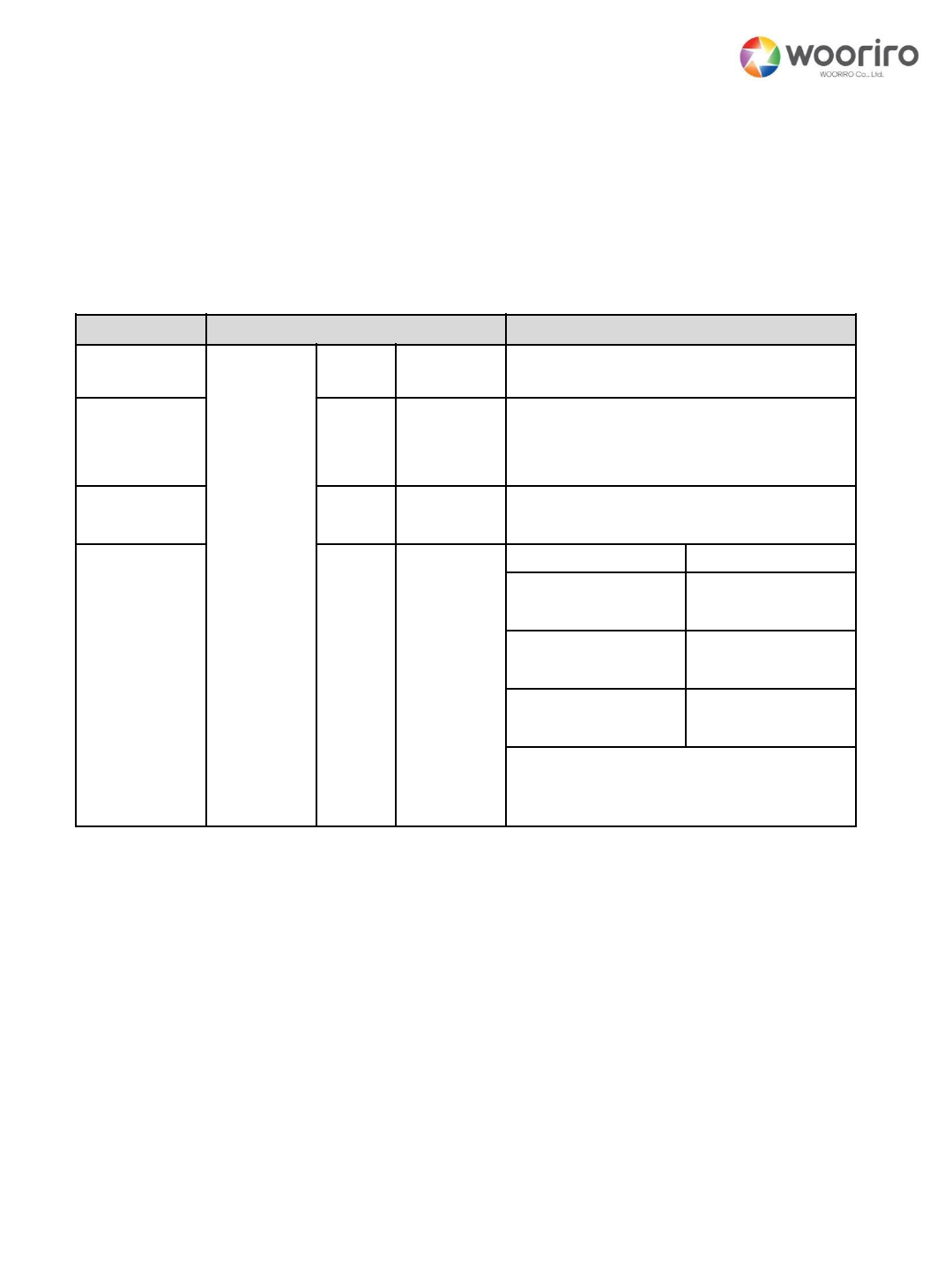
6. Product wiring
WDR210
Master Module(external)
12VDC GND Master(pc)
Serial Comm (UART-USB conveter)
6.1. General Wiring Method
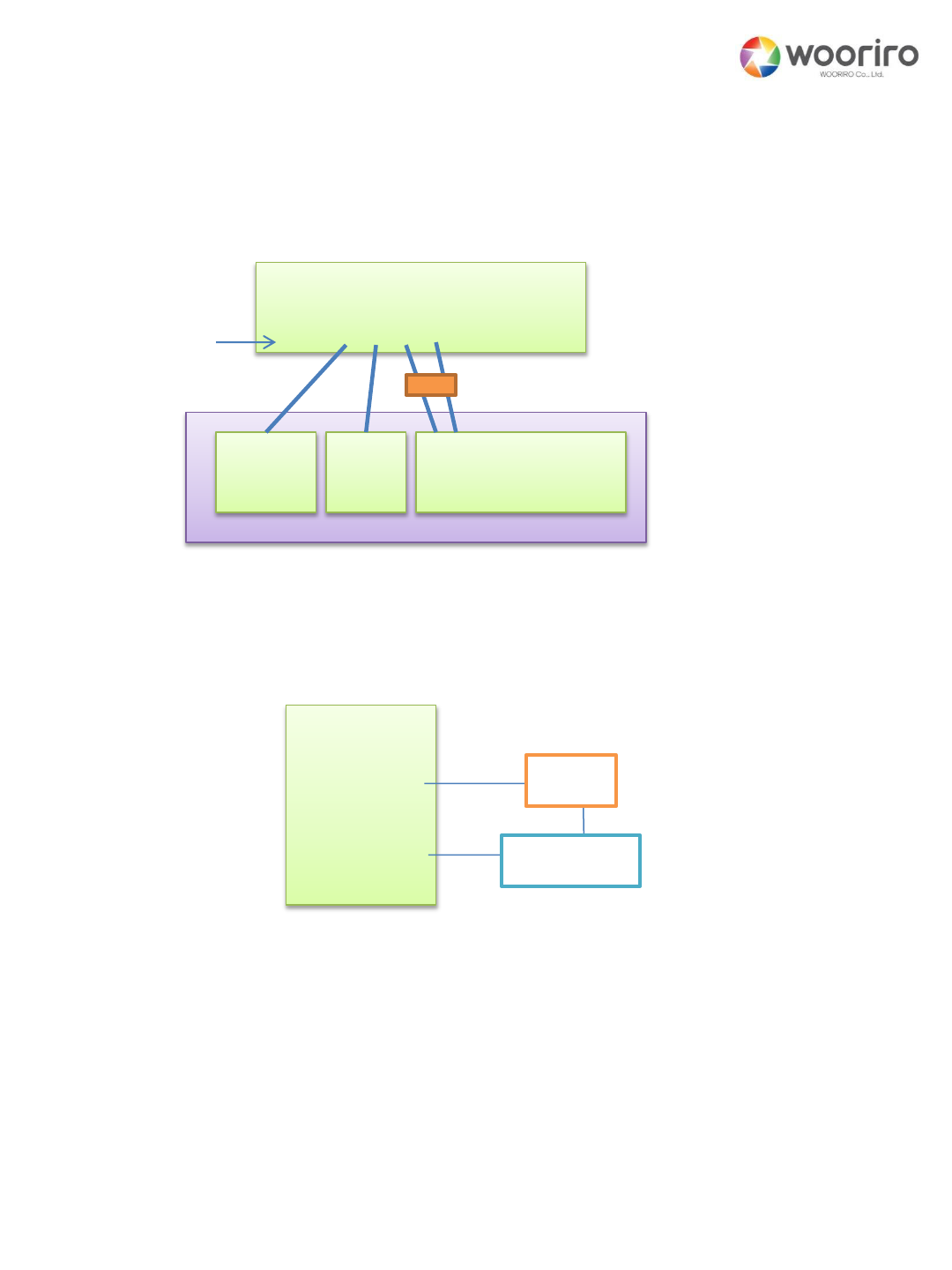
6.2. Wiring for operation test(an example)
Pin#
Pin# LED
Resistor
2MT3005-X08200
Connector

CONFIDENTIAL AND PROPRIETARY
The information contained in this document shall remain the sole and exclusive property of Wooriro Co., LTD and shall not
be disclosed by the recipient to third parties without prior consent of Wooriro in writing.
8
7. Installation-Professional Installation Guide
Please read this entire manual carefully and refer to section # 2,
3, 5, and 6 in this manual regarding position, direction and
angle selection process.
Considering antenna as eyes and then approximately selecting the
coverage. (If there is any difficulty in installation, send us the
document and/or photograph, then we will help you to selection.)
Confirming your selection
①Set to maximum Tx power (refer “5.3.1” of this manual)
②Check your coverage selection.
③Check your wiring.(refer “6 Product Wiring”)
④Wait about 2 seconds after power on.
⑤Check the blind spots. – If not enough change the direction
and/or sensitivity.
For more information and trouble shooting, please contact your
local distributor or websit: http://www.wooriro.com/english/
company/05.asp

CONFIDENTIAL AND PROPRIETARY
The information contained in this document shall remain the sole and exclusive property of Wooriro Co., LTD and shall not
be disclosed by the recipient to third parties without prior consent of Wooriro in writing.
9
ESD-INFORMATION
This Wooriro sensor is sensitive to damage from ESD.
Normal precautions as usually applied to ESD sensitive
devices are sufficient when handling the device.
Touching the signal output pins has to be avoided at
any time before soldering or plugging the device into a
motherboard.
APPROVAL
Wooriro Standard Product. Changes will not be notified as long as there
is no influence on form, fit and within this datasheet specified function of
the product.
This Data Sheet contains the technical specifications of the described
product. All previous versions of this Data Sheet are no longer valid.
FOR MOBILE DEVICE USAGE (>20cm/low power)
Radiation Exposure Statement:
This equipment complies with FCC radiation exposure limits set forth for an
uncontrolled environment. This equipment should be installed and operated
with minimum distance 20cm between the radiator & your body.

Federal Communication Commission Interference Statement
This device complies with Part 15 of the FCC Rules.Operation is subject to the
following two conditions: (1) This device may not cause harmful interference, and
(2) this device must accept any interference received, including interference that
may cause undesired operation.
This equipment has been tested and found to comply with the limits for aClass B
digital device, pursuant to Part 15 of the FCC Rules.These limits are designed to
provide reasonable protection against harmful interference in aresidential
installation.This equipment generates, uses and can radiate radio frequency
energy and, if not installed and used in accordance with the instructions, may
cause harmful interference to radio communications.However, there is no
guarantee that interference will not occur in aparticular installation. If this
equipment does cause harmful interference to radio or television reception, which
can be determined by turning the equipment off and on, the user is encouraged to
try to correct the interference by one of the following measures:
-Reorient or relocate the receiving antenna.
-Increase the separation between the equipment and receiver.
-Connect the equipment into an outlet on acircuit different from that
to which the receiver is connected.
-Consult the dealer or an experienced radio/TV technician for help.

FCC Caution:Any changes or modifications not expressly approved by the party
responsible for compliance could void the user's authority to operate this
equipment.
This transmitter must not be co-located or operating in conjunction with any other
antenna or transmitter.