WOORIRO WDR300 24GHz micro Doppler Radar User Manual
WOORIRO CO., LTD. 24GHz micro Doppler Radar
WOORIRO >
User Manual
CONFIDENTIAL AND PROPRIETARY
The information contained in this document shall remain the sole and exclusive property of Wooriro Co., LTD and shall not
be disclosed by the recipient to third parties without prior consent of Wooriro in writing.
Operation Manual (Model:WDR300)
Ver. 1.0 – 07/26/2017
1
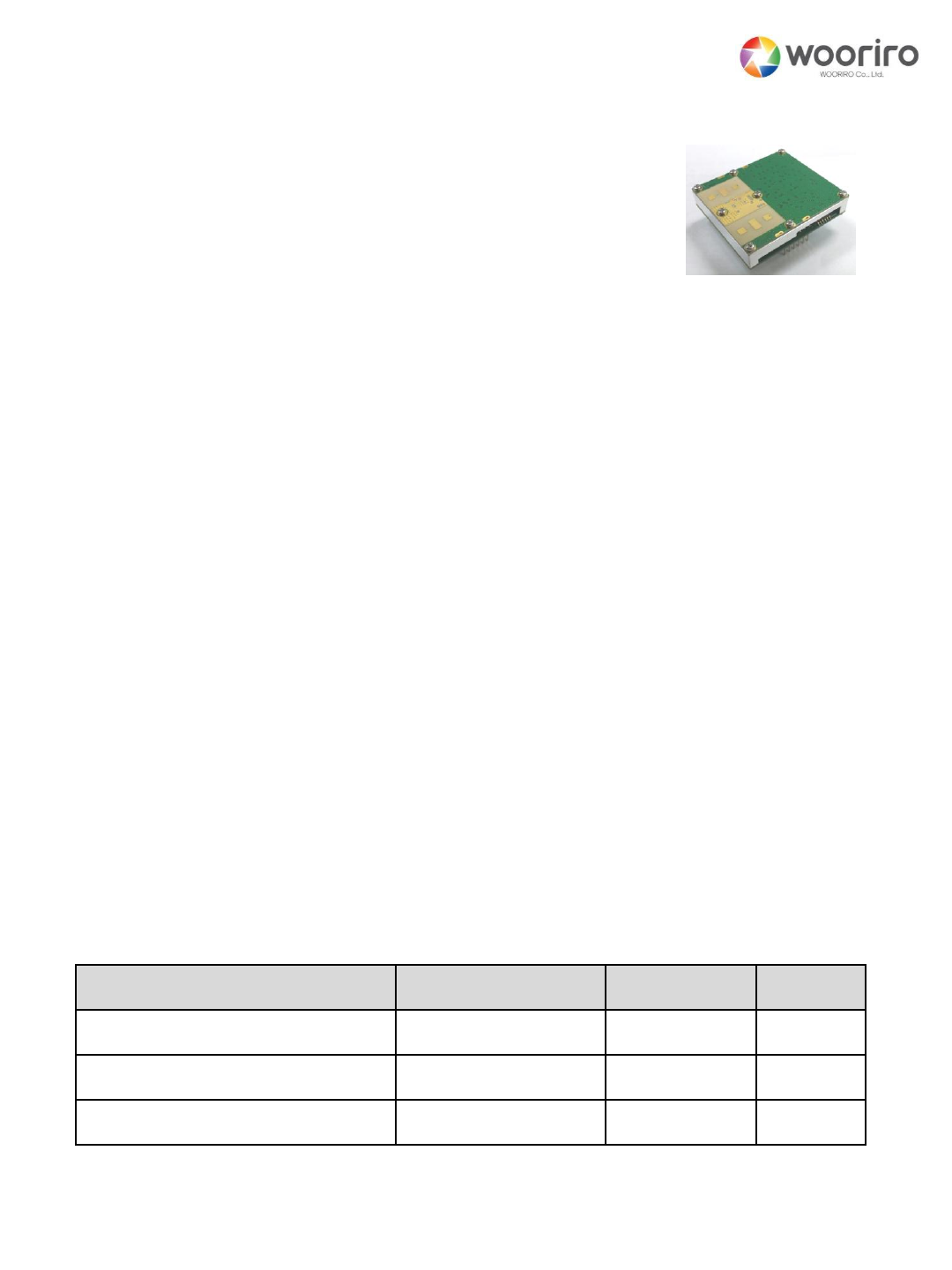
1. Features and Applications
This motion-detection radar(Model: WDR300) operating at 24GHz ISM
band, is a Doppler radar sensor detecting even minute movement of human
or objects in real time.
It detects up to 40 m, which is longer than the other conventional sensors
and insensitive to the environmental change such as light, ambient
temperature, dust etc.
Maximum detection distance can be adjustable and be doubles by
cascading connection of the same sensors.
User friendly designs such as small form factor, single 5VDC power supply
and wired/wireless communication interfaces provides easy application of
this device.
For outdoor usage, it adopts an algorithm differentiate motions between
natural and artificial motion (especially for human).
The sensor is suitable for the energy saving application by motuion
detection.
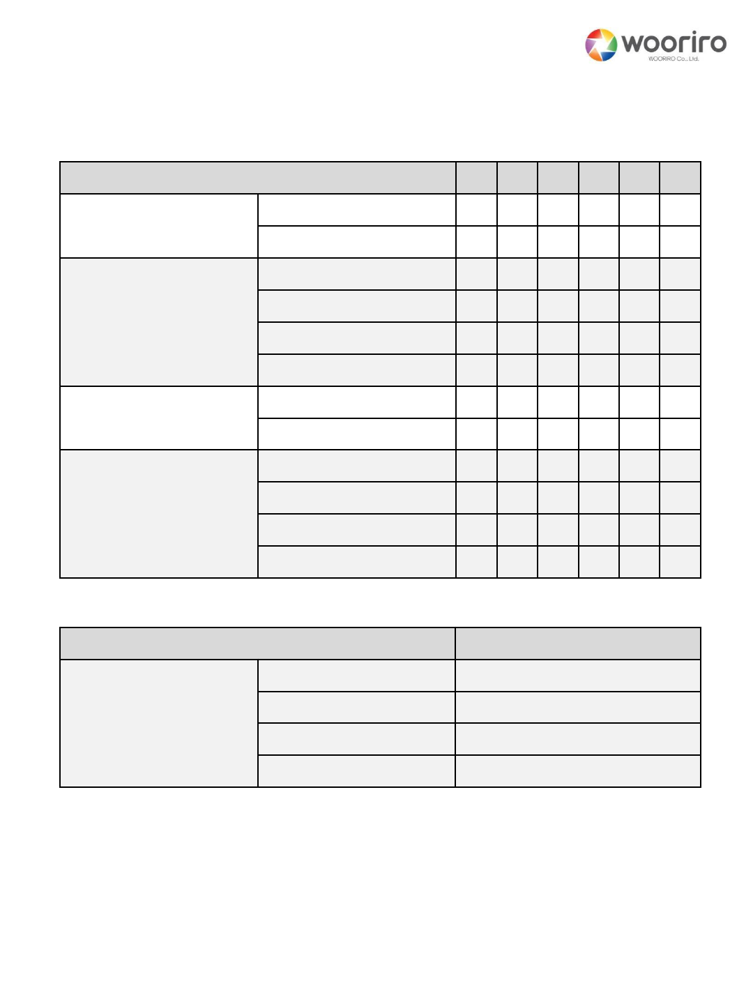
2. Maximum Ratings
Items
Symbol
Rating
Unit
DC power supply
VDC
+5
VDC
Operating Temperature
TC
-40 to +85
℃
Storage Tem[erature
TSTG
-50 to +130
℃
CONFIDENTIAL AND PROPRIETARY
The information contained in this document shall remain the sole and exclusive property of Wooriro Co., LTD and shall not
be disclosed by the recipient to third parties without prior consent of Wooriro in writing.
2
Item
Performance
Note
Tx Frequency
24.05~24.25 GHz
ISM band
Tx EIRP
13dBm
Antenna
Beam Width
60o x 35o
horizontal x vertical –
half power
Polarization
linear
Velocity
0.2m/s~3m/s
3m/s~30m/s
Low detection mode
High detection
Update Rate*
0.5Hz/10Hz
Low detection mode/
High detection
Outline
50 x 45 x 10 mm3
Interface
Header 6pin
Power Supply Voltage
+5 VDC
Power Consumption
1.0W
* Target classification algorithm is applied only to the low detection mode
3. Performance Characteristics
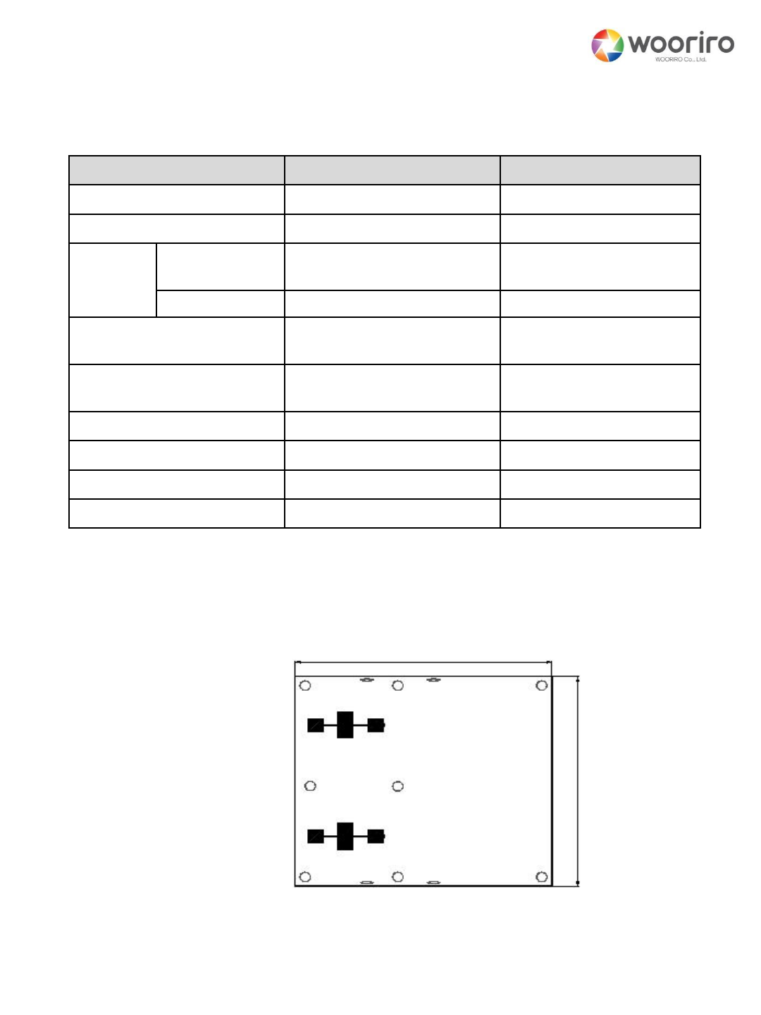
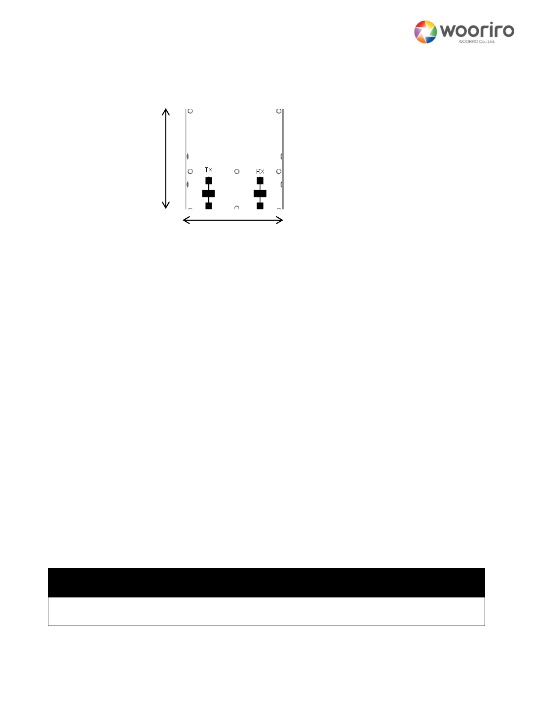
4. Product Outline and Dimensions
TX RX
45.0±0.3
Top View
CONFIDENTIAL AND PROPRIETARY
The information contained in this document shall remain the sole and exclusive property of Wooriro Co., LTD and shall not
be disclosed by the recipient to third parties without prior consent of Wooriro in writing.
3
7.5
9.5
18.1
11.5
0.6
DIP SW 6PIN
1
1.0
1.0
4 . 0 24.0 18.0 4 . 0
2.54
2.5
2.0
PIN1
AUX Serial
Side View
Bottom View
41.0
15.4
46.0
5.1
Header 2PIN
Header 6PIN
PIN1
CONFIDENTIAL AND PROPRIETARY
The information contained in this document shall remain the sole and exclusive property of Wooriro Co., LTD and shall not
be disclosed by the recipient to third parties without prior consent of Wooriro in writing.
4
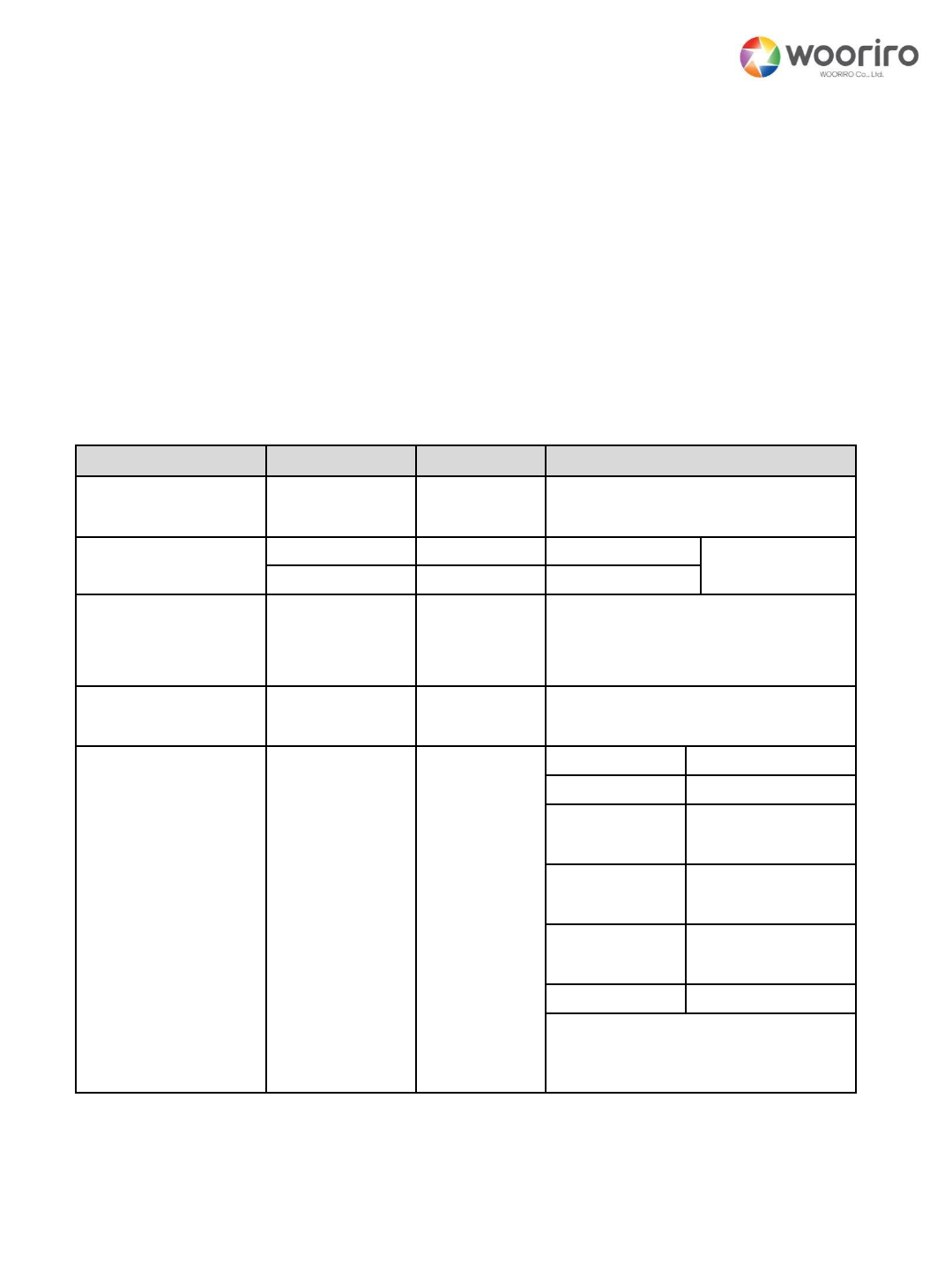
5. Set Fuctions
Connector
Pin#
Function
Description
Header 6pin
1
VDC
+5VDC
2
GND
GND
3
GPIO
3.3V D-Output
( “High” @detection)
4
PWM*
LED dimming usage
5
UART_TX*
RS485-B(option)
6
UART_RX*
RS485-A(option)
Header 2pin
For mechanical fixing purpose only
* See AN300-1
5.1. Header-pin Connector
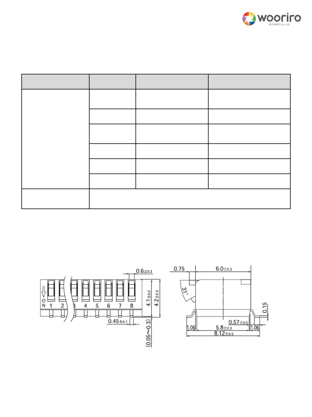
5.2. DIP Switch
5
5.2. DIP Switch
Function \ Pin#
#6
#5
#4
#3
#2
#1
Line-voltage rejection
50Hz
0
60Hz ()
1
Sensitivity
Max -3
0
0
Max-2
0
1
Max-1
1
0
Max (default)
1
1
Serial Communication
Enable
0
Disable (default)
1
Tx CW Frequency
Low
0
0
Medium
0
1
High
1
0
Default
1
1
Note : “0”=“ON” and “1”=“OFF”
Fuction
Frequency [GHz]
Tx CW Frequency
Low
24.07 +/- 0.01
Medium
24.125 +/- 0.01
High
24.23 +/- 0.01
Default
24.17 +/- 0.01
CONFIDENTIAL AND PROPRIETARY
The information contained in this document shall remain the sole and exclusive property of Wooriro Co., LTD and shall not
be disclosed by the recipient to third parties without prior consent of Wooriro in writing.
5.3. Serial Communication
CONFIDENTIAL AND PROPRIETARY
The information contained in this document shall remain the sole and exclusive property of Wooriro Co., LTD and shall not
be disclosed by the recipient to third parties without prior consent of Wooriro in writing.
5.3.1. MasterWDR300 (2-byte)
Function
MSB byte
LSB byte
Note
Line Voltage
Rejection
0X01
0X{value}
{value} = 0 or 1
Sensitivity
0X02
0X{value}
Slow detection
{value}== 0~9,
9 max
0XF2
0X{value}
Fast detection
Tx CW Frequency
0X03
0D{value}
{value} =0~250
Tx_Frrequency=24,000MHz
+{value}MHz
Tx Off
0X04
0X{value}
{value} = 1 Tx Off
otherwise Tx On
Raw Data/
Report Detection/
Report Setting
Values
0X05
0X{value}
{value} = 01
Raw data(slow)
{value} = F1
Raw data(fast)
{value} =02*
Report
Detection(short)
{value} =03
Report
Detection(long)
{value} =04
Report Setting
Values
otherwise
Disable
All are one-time report except
“Report detection”(continuous
report)
* Default setting
6
To use “serial mode”, “#3”-pin of DIP Switch6 muse be set to “ON”(=“0”;
enable)
Baud rate = 256kbps, Parity = none, Data bits = 8bit, Stop = 1bit
See AN300-1 for the details
WDR300
CONFIDENTIAL AND PROPRIETARY
The information contained in this document shall remain the sole and exclusive property of Wooriro Co., LTD and shall not
be disclosed by the recipient to third parties without prior consent of Wooriro in writing.
7
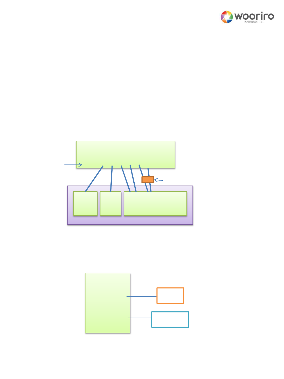
5.3.2. WDR300Master
6. Product wiring
WDR300
Master Module(external)
5VDC Master(pc)
Header6oin
Serial Comm(UART-USB conveter)
6.1. General Wiring Method
6.2. Wiring for operation test(an example)
Header#
Header# LED
Resitor
Response of Raw Data/Report Detection/Report Setting Values
See AN300-1 for the details
GND

CONFIDENTIAL AND PROPRIETARY
The information contained in this document shall remain the sole and exclusive property of Wooriro Co., LTD and shall not
be disclosed by the recipient to third parties without prior consent of Wooriro in writing.
8
7. Installation
Before installation, you must read “appendix 1” carefully that describes
the detection angle of the sensor.
Selecting Installation position, direction and angle.
Considering antenna as eyes and then approximately selecting the
coverage. (If there is any difficulty in installation, send us the
document and/or photograph, then we will help you to selection.)
Confirming your selection
①Set to maximum sensitivity (refer “5.2” if this manual)
②Check your coverage selection.
③Check your wiring.(refer chapter 6)
④Wait about 2 seconds after power on.
⑤Check the blind spots. – If not enough change the direction
and/or sensitivity.

CONFIDENTIAL AND PROPRIETARY
The information contained in this document shall remain the sole and exclusive property of Wooriro Co., LTD and shall not
be disclosed by the recipient to third parties without prior consent of Wooriro in writing.
9
FCC Statement
Federal Communication Commission Interference Statement
This equipment has been tested and found to comply with the limits
for a Class B digital device, pursuant to Part 15 of the FCC Rules.
These limits are designed to provide reasonable protection against
harmful interference in a residential installation. This equipment
generates, uses and can radiate radio frequency energy and, if not
installed and used in accordance with the instructions, may cause
harmful interference to radio communications. However, there is no
guarantee that interference will not occur in a particular installation. If
this equipment does cause harmful interference to radio or television
reception, which can be determined by turning the equipment off and
on, the user is encouraged to try to correct the interference by one of
the following measures:
● Reorient or relocate the receiving antenna.
● Increase the separation between the equipment and receiver.
● Connect the equipment into an outlet on a circuit different from
that to which the receiver is connected.
● Consult the dealer or an experienced radio/TV technician for help.
This device complies with Part 15 of the FCC Rules. Operation is
subject to the following two conditions: (1) This device may not cause
harmful interference, and (2) this device must accept any interference
received, including interference that may cause undesired operation.

1
OEM/Integrators Installation Manual
IMPORTANT NOTE:
This module is intended for OEM integrator only. The OEM integrator is
responsible for the compliance to all the rules that apply to the
product into which this certified RF module is integrated.
Additional testing and certification may be necessary when multiple
modules are used.
Any changes or modifications not expressly approved by the
manufacturer could void the user's authority to operate this
equipment.
OEM integrator are responsible for ensuring that the end-user has no
manual instructions to remove or install module.
“The grantee (Wooriro Co,. Ltd.) will offer guidance to the host manufac
turer if requested in order to assist in Subpart B issues.”
USERS MANUAL OF THE END PRODUCT:
The end user has to also be informed that any changes or
modifications not expressly approved by the manufacturer could void
the user's authority to operate this equipment.
If the labeling area is smaller than the palm of the hand, then
additional FCC part 15.19 statement is required to be available in the
users manual: This device complies with Part 15 of FCC rules.
Operation is subject to the following two conditions: (1) this device
may not cause harmful interference and (2) this device must accept
any interference received, including interference that may cause
undesired operation.
CONFIDENTIAL AND PROPRIETARY
The information contained in this document shall remain the sole and exclusive property of Wooriro Co., LTD and shall not
be disclosed by the recipient to third parties without prior consent of Wooriro in writing.

CONFIDENTIAL AND PROPRIETARY
The information contained in this document shall remain the sole and exclusive property of Wooriro Co., LTD and shall not
be disclosed by the recipient to third parties without prior consent of Wooriro in writing.
2
LABEL OF THE END PRODUCT:
The final end product must be labeled in a visible area with the
following " Contains TX FCC ID: 2AM57WDR300".
If the labeling area is larger than the palm of the hand, then the
following FCC part 15.19 statement has to also be available on the
label: This device complies with Part 15 of FCC rules. Operation is
subject to the following two conditions: (1) this device may not cause
harmful interference and (2) this device must accept any interference
received, including interference that may cause undesired operation.
Ant.
Brand
Model Name
Antenna Type
Connector
Gain(dBi)
1
WooriRadar
WDR300
Patch Array
Antenna
N/A
8.25

CONFIDENTIAL AND PROPRIETARY
The information contained in this document shall remain the sole and exclusive property of Wooriro Co., LTD and shall not
be disclosed by the recipient to third parties without prior consent of Wooriro in writing.
10
CE Statement
For MPE Statement – Mobile device
This equipment complies with EU radiation exposure limits set forth for
an uncontrolled environment. This equipment should be installed and
operated with minimum distance 20cm between the radiator & your
body.
All operational modes
Operational mode: 24GHz radar detection
The frequency and the maximum transmitted power in EU are listed
below:
24.07GHz~24.23GHz : 11.40 dBm
Hereby , [WOORIRO Co., Ltd.] declares that the radio equipment type
[WDR300] is in compliance with Directive 2014/53/EU.
The full text of the
EU declaration of conformity is available at the following internet
address:
www.wooriro.com

CONFIDENTIAL AND PROPRIETARY
The information contained in this document shall remain the sole and exclusive property of Wooriro Co., LTD and shall not
be disclosed by the recipient to third parties without prior consent of Wooriro in writing.
11
ESD-INFORMATION
This Wooriro sensor is sensitive to damage from ESD.
Normal precautions as usually applied to ESD sensitive
devices are sufficient when handling the device.
Touching the signal output pins has to be avoided at
any time before soldering or plugging the device into a
motherboard.
APPROVAL
Wooriro Standard Product. Changes will not be notified as long as there
is no influence on form, fit and within this datasheet specified function of
the product.
This Data Sheet contains the technical specifications of the described
product. All previous versions of this Data Sheet are no longer valid.
CONFIDENTIAL AND PROPRIETARY
The information contained in this document shall remain the sole and exclusive property of Wooriro Co., LTD and shall not
be disclosed by the recipient to third parties without prior consent of Wooriro in writing.
Appendix 1 : Antenna detection angle
12
Horizontal = 60o
Vertical = 35o
Appendix 2: Radome Design
Radome is the case of antenna part. The sensitivity may be greatly
degraded unless properly designed.
This table is a rule-of-thumb design rule.
Thickness
Meterial
Spacing
<2.0mm
plastic
6.2+/-2mm
Antenna consist of 2 parts; Tx and rx. They are same1x3 patch type
having 60 degree horizontal half-power beam width and 35 degree
vertical half-power beam width.
Horizontal/vertical are not absolute and can be rotated for your own
purpose.
The beam-shape is fan shaped but at short range the coverage angle
become wider. The actual detection profile is similar to a balloon. Note
there is a trade-off between near blind spots and maximum detection
range. This trade-off becomes more serious when the installation height
becomes higher.