WOOSIM SYSTEMS PORTI-W25 Thermal Printer User Manual NewManual Porti W
Woosim System Inc. Thermal Printer NewManual Porti W
UserManual.wiki
>
WOOSIM SYSTEMS
>
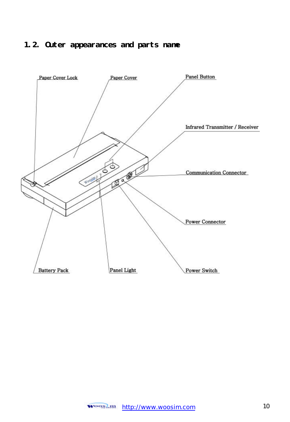
PORTI W25 User Manual
Users Manual
Navigation menu
Upload a User Manual
Namespaces
Wiki Guide
HTML
PDF
Info
Views
User Manual
Discussion / Help
Navigation
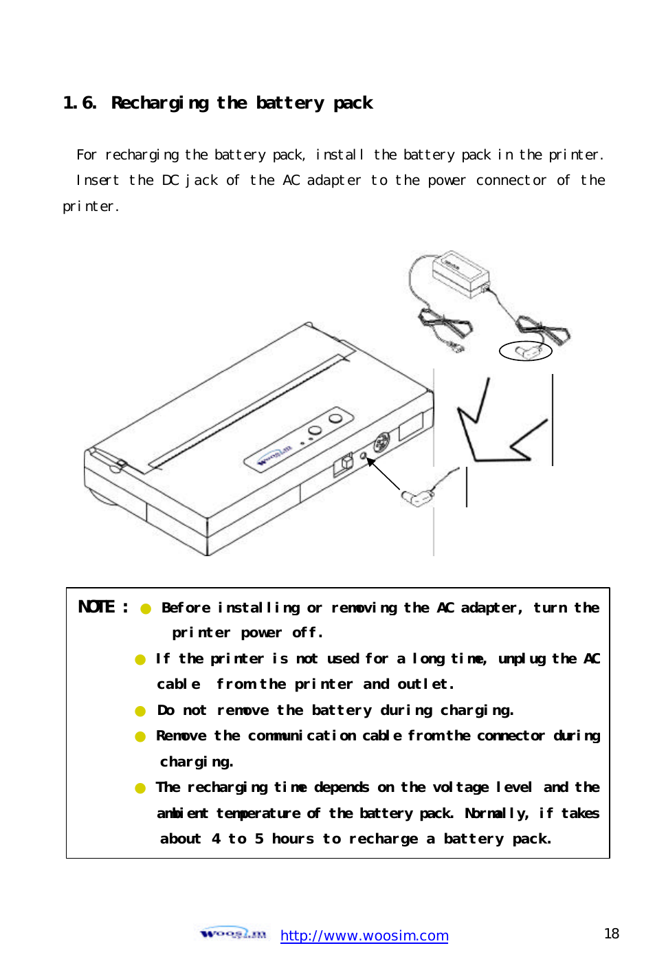
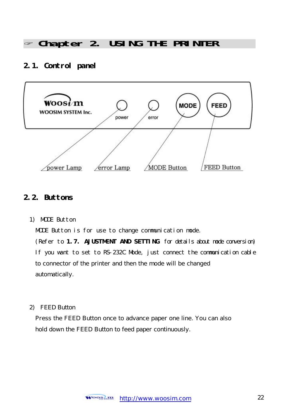
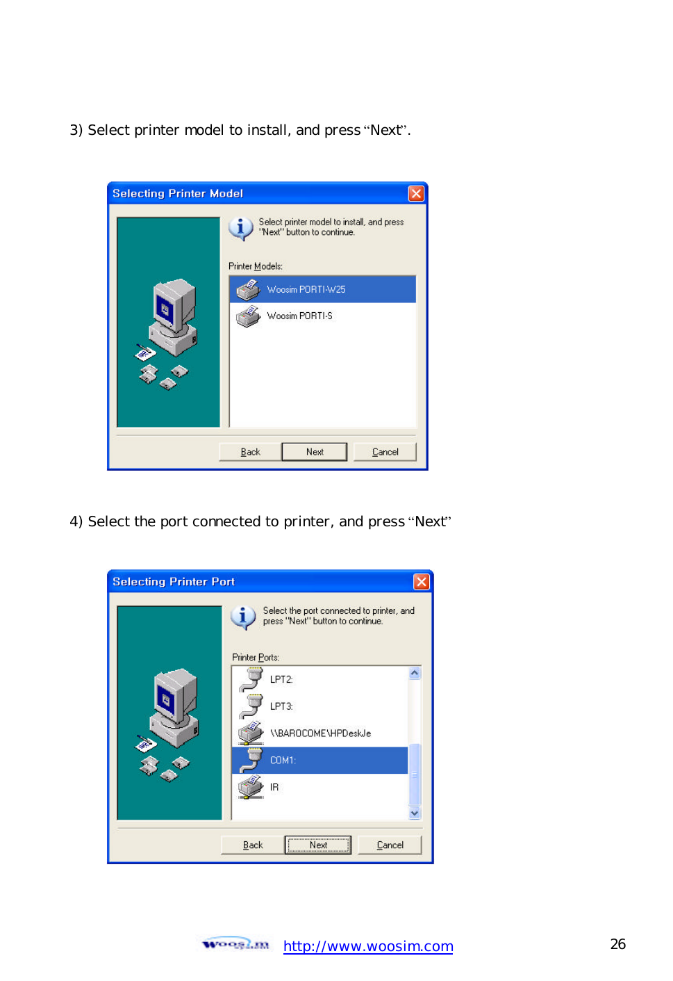
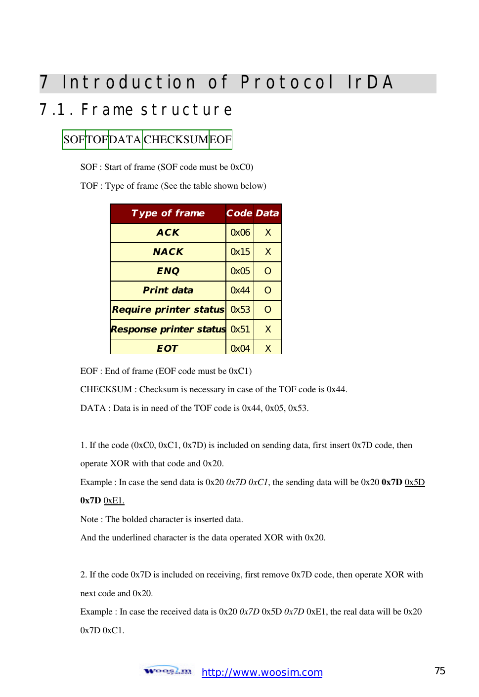
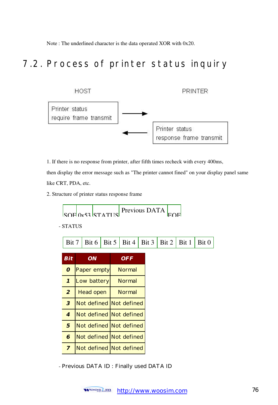
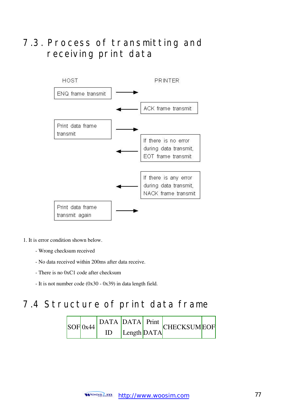
![http://www.woosim.com 35 6.1. Print Command The PORTI-W25 supports the following commands for printing character and advancing paper: CCoommmmaanndd NNaammee LF Print and line feed ESC J Print and feed paper ESC d Print and feed n lines FF Print and return to standard mode(in page mode) ESC FF Print data in page mode LF [Name] Print and line feed [Format] ASCII LF HEX 0A Decimal 10 [Description] Print the data in the print buffer and feeds one line based on the current line spacing. [Note] This command sets the print position to the beginning of the line. [Reference] ESC 2, ESC 3 ESC J n [Name] Print and feed paper. [Format] ASCII ESC J n HEX 1B 4A n Decimal 27 74 n [Range] 0 ≤ n ≤ 255 [Description] Prints the data in the print buffer and feeds the paper [n x (vertical or horizontal motion unit)] inches.](https://usermanual.wiki/WOOSIM-SYSTEMS/PORTI-W25/User-Guide-286165-Page-35.png)
![http://www.woosim.com 36 ESC d n [Name] Print and feed n lines [Format] ASCII ESC d n HEX 1B 64 n Decimal 27 100 n [Range] 0 ≤ n ≤ 255 [Description] Prints the data in the print buffer and feeds n lines. [Note] 1) This command sets the print starting position to the beginning of the line. 2) This command does not affect the line spacing set by ESC 2 or ESC 3. [Reference] ESC 2, ESC 3 FF [Name] Print and return to standard mode in page mode. [Format] ASCII FF HEX 0C Decimal 12 [Description] Prints the data in the print buffer collectively and returns to standard mode. [Note] 1) The buffer data is deleted after being printed. 2) The Printing area set by ESC W is reset to the default setting. 3) This command sets the print position to the beginning of the line. 4) This command is enabled only in page mode. [Reference] ESC FF, ESC L, ESC S ESC FF [Name] Print data in page mode. [Format] ASCII ESC FF HEX 1B 0C Decimal 27 12 [Description] In page mode, prints all buffered data in the printing area collectively. [Note] This commands is enabled only in page mode. After printing the printer does not clear the buffered data, setting values for ESC T and ESC W, and the position for buffering. [Reference] FF, ESC L, ESC S](https://usermanual.wiki/WOOSIM-SYSTEMS/PORTI-W25/User-Guide-286165-Page-36.png)
![http://www.woosim.com 37 6.2. Line Spacing Command The PORTI-W25 supports the following commands for setting line spacing. These commands only set the line spacing; they do not actually advance the paper. The line spacing set using these commands affects the results of LF and ESC d and paper feeding by using the FEED button. CCoommmmaanndd NNaammee ESC 2 Select default line spacing ESC 3 Set line spacing ESC 2 [Name] Select default line spacing [Format] ASCII ESC 2 HEX 1B 32 Decimal 27 50 [Description] Selects 1/7 inch line (approximately 3.75mm) spacing. [Note] The line spacing can be set independently in standard mode and in page mode. [Reference] ESC 3 ESC 3 n [Name] Set line spacing [Format] ASCII ESC 3 n HEX 1B 33 n Decimal 27 51 n [Range] 0 ≤ n ≤ 255 [Description] Sets the line spacing to [n x vertical or horizontal motion until] inches. [Note] 1) The line spacing can be set independently in standard mode and in page mode. 2) The horizontal and vertical motion unit are specified by GS P. Changing the horizontal or vertical motion unit does not affect the current line spacing.](https://usermanual.wiki/WOOSIM-SYSTEMS/PORTI-W25/User-Guide-286165-Page-37.png)
![http://www.woosim.com 38 3) The GS P command can change the horizontal (and vertical) motion unit. However, the value cannot be less than the minimum vertical movement amount, and it must be in even units of the minimum vertical movement amount. 4) In standard mode, the vertical motion unit (y) is used. 5) In page mode, this command functions as follows, depending on the starting position of the printable area: When the starting position is set to the upper left or lower right of the printable area using ESC T, the vertical motion unit(y) is used. When the starting position is set to the upper right or lower left of the printable area using ESC T, the horizontal motion unit(x) is used. [Reference] ESC 2, GS P 6.3. Character Commands The PORTI-W25 supports the following commands for setting character font and size: CCoommmmaanndd NNaammee ESC SP Set right-side character spacing ESC R Select an international character set ESC ! Select print mode ESC - Turn underline mode on/off ESC E Turn emphasized mode on/off ESC G Turn double-strike mode on/off ESC { Turn upside-down GS ! Select character size GS B Turn white/black reverse printing mode on/off](https://usermanual.wiki/WOOSIM-SYSTEMS/PORTI-W25/User-Guide-286165-Page-38.png)
![http://www.woosim.com 39 ESC SP n [Name] Set right-side character spacing. [Format] ASCII ESC SP n HEX 1B 20 n Decimal 27 32 n [Range] 0 ≤ n ≤ 255 [Description] Sets the character spacing for the right side of the character to [n x horizontal or vertical motion units] inches. [Note] 1) The right side character spacing for double-width mode is twice the normal value. When characters are enlarged, the right side character spacing is n times normal value. 2) This command sets values independently in each mode. 3) The horizontal and vertical motion unit are specified by GS P. Changing the horizontal or vertical motion unit does not affect the current right-side spacing. 4) The maximum right side spacing if 255/180 inches, Any setting exceeding the maximum is converted to the maximum automatically. [Default] n = 0 [Reference] GS P ESC R n [Name] Select an international character set. [Format] ASCII ESC R n HEX 1B 52 n Decimal 27 82 n [Range] 0 ≤ n ≤ 10 [Description] Selects an international character set n from the following table.](https://usermanual.wiki/WOOSIM-SYSTEMS/PORTI-W25/User-Guide-286165-Page-39.png)
![http://www.woosim.com 40 [Default] n = 0 ESC ! n [Name] Select print mode. [Format] ASCII ESC ! n HEX 1B 21 n Decimal 27 33 n [Range] 0 ≤ n ≤ 255 [Description] Select print mode(s) using n as follows,. n Character set n Character set 0 U.S.A 6 Sweden 1 France 7 Italy 2 Germany 8 Spain 3 U.K 9 Norway 4 Denmark 10 Denmark II Bit Off / On Hex Decimal Function Off 00 0 Character font A (12 x 24) 0 On 01 1 Character font B (9 x 24) Off - - Undefined 1 On - - Undefined Off - - Undefined 2 On - - Undefined Off 00 Emphasized mode not selected 3 On 10 Emphasized mode selected Off 00 Double-height mode not selected 4 On 20 Double-height mode selected Off 00 Double-width mode not selected 5 On 20 Double-width mode selected Off - - Undefined 6 On - - Undefined Off 00 0 Underline mode not selected 7 On 80 128 Underline mode selected](https://usermanual.wiki/WOOSIM-SYSTEMS/PORTI-W25/User-Guide-286165-Page-40.png)
![http://www.woosim.com 41 [Note] 1) When both double-height and double-width modes are selected, quadruple size characters are printed. 2) The printer can underline all characters, but can not underline the space set by HT. 3) The thickness of the underline is that selected by ESC -, regardless of the character size. 4) When some characters in a line are double or mode height, all the characters on the line are aligned at the baseline. 5) ESC – can also turn on or off underline mode. However, the setting of the last received command is effective. 7) GS ! can also select character size. However, the setting of the last received command is effective. [Reference] ESC -, ESC E, GS! ESC - n [Name] Turn underline mode on/off [Format] ASCII ESC - n HEX 1B 2D n Decimal 27 45 n [Range] 0 ≤ n ≤ 1 [Description] Turns underline mode on or off, based on the following values of n; [Notes] 1) The printer can underline all characters (including right-side character spacing), but cannot underline the space set by HT. 2) The printer cannot underline white/black inverted characters. 3) When underline mode id turned off by setting the value of n to 0 or 48, the n Function 0, 48 Turns off underline mode 1. 49 Turns on underline mode (1 dot thick). 2, 50 Turns on underline mode (2 dot thick)](https://usermanual.wiki/WOOSIM-SYSTEMS/PORTI-W25/User-Guide-286165-Page-41.png)
![http://www.woosim.com 42 following data is not underlined, and the underline thickness set before the mode is turned off does not change. The default underline thickness is 1 dot. 4) Changing the character size does not affect the current underline thickness. 5) Underline mode can also be turned on or off by using ESC !. Note, however, that the last received command is effective. [Default] n = 0 [Reference] ESC ! ESC E n [Name] Turn emphasized mode On/Off. [Format] ASCII ESC E n HEX 1B 45 n Decimal 27 69 n [Range] 0 ≤ n ≤ 255 [Description] Turns emphasized mode on of off. When the LSB(least significant bit) is 0, emphasized mode is turned off. When the LSB(least significant bit) is 1, emphasized mode is turned on. [Note] 1) Only the least significant bit of n is enabled. 2) This command and ESC ! turn on and off emphasized mode in the same way. Be careful when this command is used with ESC ! [Default] n = 0 [Reference] ESC ! ESC { n [Name] Turn On/Off upside-down printing mode [Format] ASCII ESC { n HEX 1B 7B n Decimal 27 123 n [Range] 0 ≤ n ≤ 255 [Description] Turns upside-down printing mode on of off When the LSB is 0, upside-down mode is turned off. When the LSB is 1, upside-down mode is turned on.](https://usermanual.wiki/WOOSIM-SYSTEMS/PORTI-W25/User-Guide-286165-Page-42.png)
![http://www.woosim.com 43 [Note] 1) Only the lowest significant bit of n is valid. 2) This command is enabled only when processed at the beginning of a line in standard mode. 3) When this command is input in page mode, the printer performs only internal flag operations. 4) This command does not affect printing in page mode. 5) In upside-down printing mode, the printer rotates the line to be printed by 180 degree and then prints it. [Default] n = 0 [Example] GS ! n [Name] Select character size [Format] ASCII GS ! n HEX 1D 21 n Decimal 29 33 n [Range] 0 ≤ n ≤ 255 [Description] (1 ≤ vertical number of times ≤ 8, 1 ≤ horizontal number of times ≤ 8) Selects the character width using bits 0 to 2 and selects the character height using bits 4 to 7, as follows;](https://usermanual.wiki/WOOSIM-SYSTEMS/PORTI-W25/User-Guide-286165-Page-43.png)
![http://www.woosim.com 44 [Notes] 1) This command is all characters effective 2) If n is outside of the defined range, this command is ignored. 3) In standard mode, the vertical direction is the paper feed direction, and the horizontal direction is perpendicular to the paper feed direction. 4) In page mode, vertical and horizontal directions are based on the character orientation. 5) When characters are enlarged with different sizes on one line, all the characters on the line are aligned at the baseline. 6) The ESC ! command can also turn double width and double height modes on or off. [Default] n = 0 [Reference] ESC ! GS B n [Name] Turn white/black reverse printing mode On/Off. [Format] ASCII GS B n HEX 1D 42 n Decimal 29 66 n [Range] 0 ≤ n ≤ 255 [Description] Turns on or off White/Black reverse printing mode. Hex Decimal Width 00 0 1 (normal) 01 1 2 (double width) 02 2 3 03 3 4 04 4 5 05 5 6 06 6 7 07 7 8 Character Width Selection Hex Decimal Height 00 0 1 (normal) 10 16 2 (double height) 20 32 3 30 48 4 40 64 5 50 80 6 60 96 7 70 112 8 Character Height Selection](https://usermanual.wiki/WOOSIM-SYSTEMS/PORTI-W25/User-Guide-286165-Page-44.png)
![http://www.woosim.com 45 [Notes] 1) When the LSB is 0, white/black reverse printing mode is turned on. 2) When the LSB is 1, white/black reverse printing mode is turned off. 3) Only the lowest bit of n is valid. 4) This command is available for built in characters and user defined characters. 5) When white/black reverse printing mode is on, it also applied to character spacing set by ESC SP. 6) This command does not affect the space between lines. 7) White/black reverse mode has a higher priority than underline mode. Even if underline mode is on, it is disabled (but not canceled) when white/black reverse mode is selected. [Default] n = 0 6.4. Panel Button Command The PORTI-W25 supports the following command for enabling and disabling the panel button. CCoommmmaanndd NNaammee ESC c 5 Enable/disable panel buttons ESC c 5 n [Name] Enable/Disable panel buttons [Format] ASCII ESC c 5 n HEX 1B 63 35 n Decimal 27 97 53 n [Range] 0 ≤ n ≤ 255 [Description] Enables or disables the panel buttons. When the LSB is 0, the panel buttons are enabled. When the LSB is 1, the panel buttons are disabled. [Notes] 1) Only the least significant bit of n is valid.](https://usermanual.wiki/WOOSIM-SYSTEMS/PORTI-W25/User-Guide-286165-Page-45.png)
![http://www.woosim.com 46 2) When the panel buttons are disabled, none of them are usable when the printer cover is closed. 3) In this printer, the panel buttons is the FEED button. 4) In the macro ready mode, the FEED button are enabled regardless of the settings of this command; however, the paper cannot be fed by using these buttons. [Default] n = 0 6.5. Print Position Commands The PORTI-W25 supports the following commands for setting the print position CCoommmmaanndd NNaammee ESC $ Set absolute print position ESC \ Set relative print position ESC a Select justification HT Horizontal tab ESC D Set horizontal tab positions GS L Set left margin GS W Set printing area width ESC W Set printing area in page mode ESC T Select print direction in page mode GS $ Set absolute vertical print position in page mode GS \ Set relative vertical print position in page mode ESC O Set print starting position. ESC $ nL nH [Name] Set absolute print position [Format] ASCII ESC $ nL nH HEX 1B 24 nL nH Decimal 27 36 nL nH [Range] 0 ≤ nL ≤ 255 0 ≤ nH ≤ 255](https://usermanual.wiki/WOOSIM-SYSTEMS/PORTI-W25/User-Guide-286165-Page-46.png)
![http://www.woosim.com 47 [Description] Set the distance from the beginning of the line to the position at which subsequent characters are to be printed. [Notes] 1) The distance from the beginning of the line to the print position is [(nL + nH x 256) x (vertical or horizontal motion unit)] inches. 2) Setting outside the specified printable area are ignored. 3) The horizontal and vertical motion unit are specified by GS P. 4) The GS P command can change the horizontal (and vertical) motion unit. However, the value cannot be less than the minimum horizontal movement amount, and it must be in even units of he minimum horizontal movement amount. 5) In standard mode, the horizontal motion unit (x) is used. 6) In page mode, horizontal or vertical motion unit differs depending on the starting position of the printable area as follows; 1. When the starting position is set to the upper left or lower right of the printable area using ESC T, the horizontal motion unit (x) is used. 2. When the starting position is set to the upper right or lower left of the printable area using ESC T, the vertical motion unit (y) is used. [Reference] ESC\, GS$, GS\, GS P ESC \ nL nH [Name] Set relative print position [Format] ASCII ESC \ nL nH HEX 1B 5C nL nH Decimal 27 92 nL nH [Range] 0 ≤ nL ≤ 255, 0 ≤ nL ≤ 255 [Description] Set the print starting position based on the current position by using [Notes] 1) This command sets the distance from the current position to [(nL+nHx256) x horizontal or vertical motion unit]](https://usermanual.wiki/WOOSIM-SYSTEMS/PORTI-W25/User-Guide-286165-Page-47.png)
![http://www.woosim.com 48 2) Any setting that exceeds the printable are is ignored 3) When pitch N is specified to the right; nL + nH x 256 = N When pitch N is specified to the left (the negative direction), use the complement of 65536. 4) The print starting position moves from the current position to [N x horizontal or vertical motion unit)] 5) The horizontal and vertical motion unit are specified by GS P. 6) The GS P command can change the horizontal (and vertical) motion unit. However, the value cannot be less than the minimum horizontal movement amount, and it must be in even units of the minimum horizontal movement amount. 7) In standard mode, the horizontal motion unit is used. 8) In page mode, the horizontal or vertical unit differs as follows, depending on the starting point of the printing area; When the starting position is set to the upper left or lower right of the printable area using ESC T, the horizontal motion unit (x) is used. When the starting position is set to the upper right or lower left of the printable area using ESC T, the vertical motion unit (y) is used. [Reference] ESC $, ESC P ESC a n [Name] Select justification [Format] ASCII ESC a n HEX 1B 61 n Decimal 27 97 n [Range] 0 ≤ n ≤ 2 48 ≤ n ≤ 50 [Description] Aligns all the data in one line to the specified position. n selects the type of justification as follows; n Justification 0, 48 Left justification 1, 49 Center justification 2, 50 Right justification](https://usermanual.wiki/WOOSIM-SYSTEMS/PORTI-W25/User-Guide-286165-Page-48.png)
![http://www.woosim.com 49 [Notes] 1) The command is enabled only when processed at the beginning of the line in standard mode. 2) If this command is input in page mode, the printer performs only internal flag operations. 3) This command has no effect in page mode. 4) This command executes justification in the printing area. 5) This command justifies the space area according to HT, ESC $ or ESC \ [Default] n = 0 [Example] HT [Name] Horizontal Tab [Format] ASCII HT HEX 09 Decimal 9 [Description] Moves the print position to the next horizontal tab position. [Note] 1) This command is ignored unless the next horizontal tab position has been set. 2) If the next horizontal tab position exceeds the printing area, the printer sets the printing position to [Printing area width + 1] 3) Horizontal tab positions are set with ESC D. 4) If this command is received when the printing position is at [Printing area width + 1], the printer executes print buffer-full printing of the current line and horizontal tab processing from the beginning of the next line. 5) The default setting of the horizontal tab position for the paper roll is every 0th character. [Reference] ESC D](https://usermanual.wiki/WOOSIM-SYSTEMS/PORTI-W25/User-Guide-286165-Page-49.png)
![http://www.woosim.com 50 ESC D n1…nk NUL [Name] Set horizontal tab positions. [Format] ASCII ESC D n1… nk NUL HEX 1B 44 n1… nk 00 Decimal 27 68 n1… nk 0 [Range] 1 <= n <= 255 0 <= k <=32 [Description] Set horizontal tab position [Notes] 1) n specifies the column number for setting a horizontal tab position from the beginning of the line. 2) k indicates the total number of horizontal tab positions to be set. 3) The horizontal tab position is stored as a value of [character width x n] measured from the beginning of the line. The character width includes the right-side character spacing, and double-width characters are set with twice the width of normal characters. 4) This command cancels the previous horizontal tab settings. 5) When setting n=8, the print position is moved to column 9 by sending HT. 6) Up to 32 tab positions (k=32) can be set. Data exceeding 32 tab positions is processed as normal data. 7) Transmit [n]k in ascending order and place a NUL code 0 at the end. 8) When [n]k is less than or equal to the preceding value [n]k-1, tab setting is finished and the following data is processed as normal data. 9) ESC D NUL cancels all horizontal tab positions. 10) The previously specified horizontal tab positions do not change, even if the character width changes. 11) The character width is memorized for each standard and page mode. [Default] The default tab positions are at intervals of 0 characters. [Reference] HT](https://usermanual.wiki/WOOSIM-SYSTEMS/PORTI-W25/User-Guide-286165-Page-50.png)
![http://www.woosim.com 51 GS L nL nH [Name] Set left margin. [Format] ASCII GS L nL nH HEX 1D 4C nL nH Decimal 29 76 nL nH [Range] 0 ≤ nL ≤ 255, 0 ≤ nH ≤ 255 [Description] Set the left margin using nL and nH. [Notes]1) The left margin is set to [(nL+nHx256)] x (horizontal motion unit) inches. 2) This command is effective only processed at the beginning of the line in standard mode. 3) If this command is input in page mode, the printer performs only internal flag operations. 4) This command does not affect printing in page mode. 5) If the setting exceeds the printable area, the maximum value of the printable area is used. 6) The horizontal and vertical motion units are specified by GS P. Changing the horizontal and vertical motion unit does not affect the current left margin. 7) The horizontal motion unit (x) is used for calculating the left margin. The calculated result is truncated to the minimum value of the mechanical pitch. [Default] nL = 0, nH = 0 [Reference] GS P, GS W](https://usermanual.wiki/WOOSIM-SYSTEMS/PORTI-W25/User-Guide-286165-Page-51.png)
![http://www.woosim.com 52 GS W nL nH [Name] Set printing area width [Format] ASCII GS W nL nH HEX 1D 57 nL nH Decimal 29 87 nL nH [Range] 0 ≤ nL ≤ 255, 0 ≤ nH ≤ 255 [Description] Sets the printing area width to the area specified by nL and nH. [Notes] 1) The printing area width is set to [(nL+nHx256)] x horizontal motion unit inches. 2) This command is effective only processed at the beginning of the line. 3) In page mode, the printer performs only internal flag operations. 4) This command does not affect printing in page mode. 5) If the [left margin + printing area width] exceeds the printable area, (printable area width - left margin) is used. 6) The horizontal and vertical motion units are specified by GS P. Changing the horizontal and vertical motion units does not affect the current left margin. 7) The horizontal motion unit (x) is used for calculating the printing area width. The calculated result is truncated to the minimum value of the mechanical pitch. 8) If the width set for the printing area is less than the width of one character, when the character data is developed, the following If the printing area width cannot be extended sufficiently, the left margin is reduced to accommodate one character.](https://usermanual.wiki/WOOSIM-SYSTEMS/PORTI-W25/User-Guide-286165-Page-52.png)
![http://www.woosim.com 53 If the printing area width cannot be extended sufficiently, the right space is reduced. 9) If the width set for the printing area is less than one line in vertical, the following processing is performed only on the line in question when data other than character data(e.g., bit image, user defined bit image) is developed: The printing area width is extended to the right to accommodate one line in vertical for the bit image within the printable area. If the printing area width cannot be extended sufficiently, the left margin is reduced to accommodate one line in vertical. [Default] nL = 0, nH = 2 [Reference] GS L, GS P ESC W xL xH yL yH dxL dxH dyL dyH [Name] Set printing area in page mode [Format] ASCII ESC W xL xH yL yH dxL dxH dyL dyH HEX 1B 57 xL xH yL yH dxL dxH dyL dyH Decimal 27 87 xL xH yL yH dxL dxH dyL dyH [Range] 0 ≤ xL,xH,yL,yH,dxL,dxH,dyL,dyH ≤255 (except dxL=dxH=0 or dyL=dyH=0) [Description] The horizontal starting position, vertical starting position, printing area width, and printing area height are defined as x0, y0, dx(inch), respectively. x0 = [(xL + xH * 256)] * (horizontal motion unit) y0 = [(yL +yH * 256)] * (vertical motion unit) dx = [(dxL + dxH x 256)] x (horizontal motion unit)](https://usermanual.wiki/WOOSIM-SYSTEMS/PORTI-W25/User-Guide-286165-Page-53.png)
![http://www.woosim.com 54 dy = [(dyL + dyH * 256)] * (vertical motion unit) The printing area is set as shown in the figure below. [Note] 1) If this commands is input in standard mode, the printer executes only internal flag operation. This command does not affect printing in standard mode. 2) If the horizontal or vertical starting position is set outside the printable area, the printer stops command processing and processes the following data as normal data. 3) If the printing area width or height is set to 0, the printer stops command processing and processes the following data as normal data. 4) This command sets the position where data is buffered to the position specified by ESC T within the printing area. 5) If (horizontal starting position + printing area width) exceeds the printable area, the printing area width is automatically set to (horizontal printable area - horizontal starting position). 6) If (vertical starting position + printing area height) exceeds the printable area, the printing area height is automatically set to (vertical printable area-vertical starting position). 7) The horizontal and vertical motion unit are specified by GS P. Changing the horizontal or vertical motion unit does not affect the current printing area. 8) The GS P command can change the horizontal (and vertical) motion unit. However, the value cannot be less than the minimum horizontal movement amount, and it must be in even units of minimum horizontal movement amount. 9) Use the horizontal motion unit (x) for setting the horizontal starting position and printing area width, and use the vertical motion unit (y) for setting the vertical starting position and printing area height. 10) When the horizontal starting position, vertical starting position, printing area width, and printing area height are defined as X, Y, Dx, Dy respectively, the printing area is set as shown in the figure below.](https://usermanual.wiki/WOOSIM-SYSTEMS/PORTI-W25/User-Guide-286165-Page-54.png)
![http://www.woosim.com 55 [Default] xL = xH = yL = yH = 0 dxL = 0, dxH = 2, dyL = 126, dyH = 6 [Reference] CAN, ESC L, ESC T, GS P ESC T n [Name] Select print direction in page mode [Format] ASCII ESC T n HEX 1B 54 n Decimal 27 84 n [Range] 0 ≤ n ≤ 3 or 48 ≤ n ≤51 [Description] Selects the print direction and starting position in page mode. n specifies the print direction and starting position as follows; n Print direction Starting position 0,48 Left to right Upper left (A in the figure) 1,49 Bottom to top Lower left (B in the figure) 2,50 Right to left Lower right (C in the figure) 3,51 Top to bottom Upper right (D in the figure)](https://usermanual.wiki/WOOSIM-SYSTEMS/PORTI-W25/User-Guide-286165-Page-55.png)
![http://www.woosim.com 56 [Notes] 1) When the command is input in standard mode, the printer executes only internal flag operation. This command does not affect printing in standard mode. 2) This command sets the position where data is buffered within the printing area set by ESC W. 3) Parameters for horizontal or vertical motion units (X or Y) differ as follows, depending on the starting position of the printing area; If the starting position is the upper left or lower right of the printing area, data is buffered in the direction perpendicular to the paper feed direction. Commands using horizontal motion unit: ESC SP, ESC $, ESC \ Commands using vertical motion unit: ESC 3, ESC J, GS $, GS \ If the starting position is the upper right or lower left of the printing area, data is buffered in the paper feed direction. Commands using horizontal motion units : ESC 3, ESC J, GS $,GS \ Commands using vertical motion units : ESC SP, ESC $, ESC \ [Default] n = 0 [Reference] ESC $, ESC L, ESC W, ESC \, GS $, GS P, GS \ GS $ nL nH [Name] Set absolute vertical print position in page mode. [Format] ASCII GS $ nL nH HEX 1D 24 nL nH Decimal 29 36 nL nH [Range] 0 ≤ nL ≤ 255, 0 ≤ nH ≤ 255 [Description] Sets the absolute vertical print starting position for buffer character data in page mode. [Notes] 1) This command sets the absolute print position to [(nL+nHx256)]x (vertical or horizontal motion unit) inches. 2) This command is effective only in page mode. 3) If the [(nL+nHx256)] x (vertical or horizontal motion unit) exceeds the specified printing area, this command is ignored. 4) The horizontal starting buffer position does not move.](https://usermanual.wiki/WOOSIM-SYSTEMS/PORTI-W25/User-Guide-286165-Page-56.png)
![http://www.woosim.com 57 5) The reference starting position is that specified by ESC T. 6) This command operates as follows, depending on the starting position of the printing area specified by ESC T; When the starting position is set to the upper left or lower right, this command sets the absolute position in the vertical direction. When the starting position is set to the upper right or lower left, this command sets the absolute position in the horizontal direction. 7) The horizontal and vertical motion unit are specified by GS P. 8) The GS P command can change the horizontal and vertical motion unit. However, the value cannot be less than the minimum horizontal movement amount, and it must be in even units of the minimum horizontal movement amount. [Reference] ESC $, ESC T, ESC W, ESC \, GS P, GS \ GS \ nL nH [Name] Set relative vertical print position in page mode [Format] ASCII GS \ nL nH HEX 1D 5C nL nH Decimal 29 92 nL nH [Range] 0 ≤ nL ≤ 255 0 ≤ nH ≤ 255 [Description] Sets the relative vertical print starting position from the current position in page mode. [Notes] 1) This command sets the distance from the current position to [(nL + nHx256)] x vertical or horizontal motion unit inches. 2) This command is ignored unless page mode is selected. 3) When pitch N is specified to the movement downward; nL + nHx256 = N When pitch N is specified to the movement upward (the negative direction), use the complement of 65536. When pitch N is specified to the movement upward; nL + nH x 256 = 65536 - N](https://usermanual.wiki/WOOSIM-SYSTEMS/PORTI-W25/User-Guide-286165-Page-57.png)
![http://www.woosim.com 58 4) Any setting that exceeds the specified printing area is ignored. 5) This command function as follows, depending on the print starting position set by ESC T; When the starting position is set to the upper left or lower right of the printing, the vertical motion unit (y) is used. When the starting position is set to the upper right or lower left of the printing, the horizontal motion unit (x) is used. 6) The horizontal and vertical motion unit are specified by GS P. 7) The GS P command can change the horizontal (and vertical) motion unit. However, the value cannot be less than the minimum horizontal movement amount, and it must be in even units of the minimum horizontal movement amount. [Reference] ESC $, ESC T, ESC W, ESC \, GS $, GS P ESC O xL xH yL yH [Name] Set print starting position. [Format] ASCII ESC O xL xH yL yH HEX 1B 4F xL xH yL yH Decimal 27 79 xL xH yL yH [Description] Set horizontal starting position and vertical starting position in page mode. Horizontal starting position = (xL + xH * 256) * (horizontal motion unit) Vertical starting position = (yL + yH * 256) * (vertical motion unit) [Note] This command is effective only in page mode.](https://usermanual.wiki/WOOSIM-SYSTEMS/PORTI-W25/User-Guide-286165-Page-58.png)
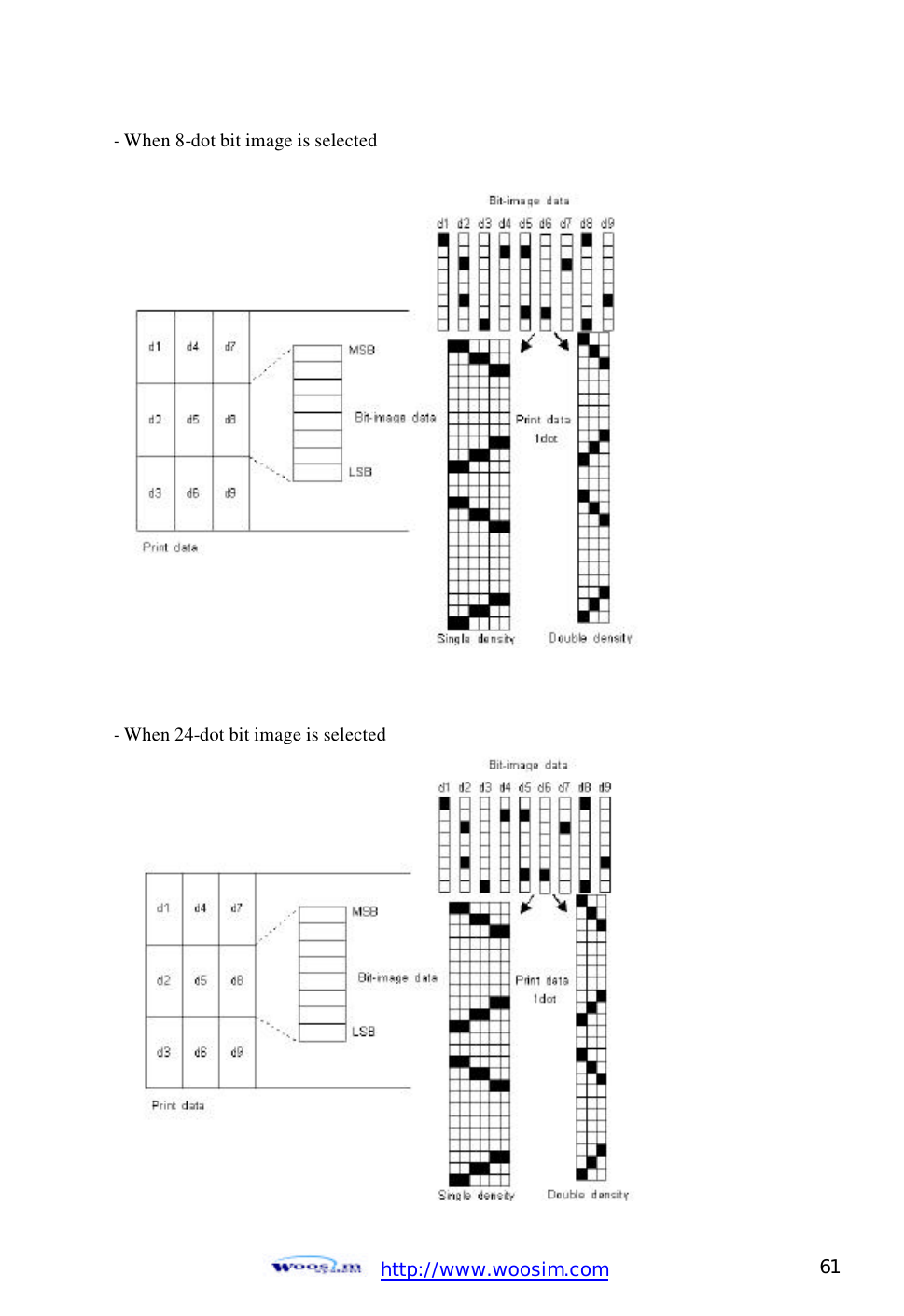
![http://www.woosim.com 59 6.6. Bit-Image Commands The PORTI-W25 supports the following bit-image command. CCoommmmaanndd NNaammee ESC * Select bit image mode ESC X 4 Define user-defined bit image ESC * m nL nH d1 dk [Name] Select bit-image mode. [Format] ASCII ESC * m nL nH d1…dk HEX 1B 2A m nL nH d1… dk Decimal 27 42 m nL nH d1… dk [Range] m = 0,1,32,33 0 ≤ nL ≤ 255 0 ≤ nH ≤ 3 0 ≤ d ≤ 255 [Description] Selects a bit-image mode using m for the number of dots specified by nL and nH, as follows: [Notes] 1) If the values of m is out of the specified range, nL and data following are processed an normal data. 2) The nL and nH indicate the number of dots of the bit image in the horizontal direction. 3) The number of dots is calculated by nL + nH x 256. Vertical direction Horizontal direction m mode Number of Dots Dot density Dot density Number of Data 0 8 dot single 8 60 DPI 90 DPI nL+nHx256 1 8 dot double 8 60 DPI 180 DPI nL+nHx256 32 24 dot single 24 180DPI 90 DPI (nL+nHx256)33 24 dot double 24 180 DPI 180 DPI (nL+nHx256)](https://usermanual.wiki/WOOSIM-SYSTEMS/PORTI-W25/User-Guide-286165-Page-59.png)
![http://www.woosim.com 62 ESC X 4 x y d1…dk [Name] Define user-defined bit-image [Format] ASCII ESC X 4 x y d1… dk HEX 1B 58 34 x y d1… dk Decimal 27 88 52 x y d1… dk [Description] ESC X 4 x y d1 ... d(x ??y) defines a user-defined bit image using x ??8 dots in the horizontal direction and y dots in the vertical direction. - Horizontal direction dots = (x * 8)dots - Vertical direction dots = (y)dots](https://usermanual.wiki/WOOSIM-SYSTEMS/PORTI-W25/User-Guide-286165-Page-62.png)
![http://www.woosim.com 63 [Note] ESC X 4 is supported in Porti_W,S produced after August,2002, but it’s not supported in others yet. [Reference] ESC W, ESC O, FF](https://usermanual.wiki/WOOSIM-SYSTEMS/PORTI-W25/User-Guide-286165-Page-63.png)
![http://www.woosim.com 64 6.7. Status Commands The PORTI-W25 supports the following status transmission command. CCoommmmaanndd NNaammee ESC v Transmit paper sensor status ESC v [Name] Transmit paper sensor status [Format] ASCII ESC v HEX 1B 76 Decimal 27 118 [Description] ESC v transmits the status of a paper sensor as 1byte of data. When the paper roll end sensor detects a paper, printer transmits the NULL(H00) data. When the paper roll end sensor doesn’t detect a paper, printer don’t Transmit anything.](https://usermanual.wiki/WOOSIM-SYSTEMS/PORTI-W25/User-Guide-286165-Page-64.png)
![http://www.woosim.com 65 6.8. Barcode Commands The PORTI-W25 supports the following barcode commands. CCoommmmaanndd NNaammee GS h Set barcode height GS w Set barcode width GS k Print bar code GS H Select printing position of Human Readable Interpretation (HRI) characters GS h n [Name] Set barcode height [Format] ASCII GS h n HEX 1D 68 n Decimal 29 104 n [Range] 0 ≤ n ≤ 255 [Description] GS h n selects the height of a barcode. n specifies the number of dots in the vertical direction. One dot corresponds 1/8mm. The default setting is n = 80. GS w n [Name] Set barcode width [Format] ASCII GS w n HEX 1D 77 n Decimal 29 119 n [Range] n = 0, 3 ≤ n ≤ 5 [Description] GS w n selects the horizontal size of a barcode. The default setting is n = 0.](https://usermanual.wiki/WOOSIM-SYSTEMS/PORTI-W25/User-Guide-286165-Page-65.png)
![http://www.woosim.com 66 ①GS k m d1…dk NUL ②GS k m n d1…dn [Name] Print barcode [Format] ①ASCII GS k m d1…dk NUL HEX 1D 6B m d1…dk 00 Decimal 29 107 m d1…dk 0 ② ASCII GS k m n d1…dn HEX 1D 6B m n d1…dn Decimal 29 107 m n d1…dn [Range] ① 0 ≤ m ≤ 6 (k and d depends on the bar code system used.) ② 0 ≤ m ≤ 6 (n and d depends on the bar code system used.) [Description] GS k m d1…dk NUL selects a barcode system and print the barcode. m specifies a bar code system as follows; ① m Barcode System Number of character Remarks 0 UPC-A 11 ≤ k ≤ 12 48 ≤ d ≤ 57 1 UPC-E 11 ≤ k ≤ 12 48 ≤ d ≤ 57 2 EAN13 11 ≤ k ≤ 13 48 ≤ d ≤ 57 3 EAN8 7 ≤ k ≤ 8 48 ≤ d ≤ 57 4 CODE39 1 ≤ k 48 ≤ d ≤ 57, 65 ≤ d ≤ 90, d = 32, 36, 37, 43, 45, 46,47 5 ITF 1 ≤ k (even number) 48 ≤ d ≤ 57 6 CODABAR 1 ≤ k 48 ≤ d ≤ 57, 65 ≤ d ≤ 68, d = 36, 43, 45, 46, 47, 58](https://usermanual.wiki/WOOSIM-SYSTEMS/PORTI-W25/User-Guide-286165-Page-66.png)
![http://www.woosim.com 67 ② [Notes] 1) This command ends with a NUL code. 2) When the bar code system used is UPC-A or UPC-E, the printer prints the bar code data after receiving 12 bytes bar code data and processes the following data as normal data. 3) When the bar code system used in EAN13, the printer prints the bar code after receiving 13 bytes bar code data and processes the following data as normal data. 4) When the bar code system used in EAN8, the printer prints the bar code after receiving 8 bytes bar code data and processes following data as normal data. 5) The number of data for ITF bar code must be even numbers. When an odd number of data is input, the printer ignores the last received data. 6) n indicates the number of bar code data, and the printer processes n bytes from the next character data as bar code data. 7) If n is outside of the specified range, the printer stops command processing and m Barcode System Number of characters Remarks 65 UPC-A 11 ≤ n ≤ 12 48 ≤ d ≤ 57 66 UPC-E 11 ≤ n ≤ 12 48 ≤ d ≤ 57 67 EAN13 11 ≤ n ≤ 13 48 ≤ d ≤ 57 68 EAN8 7 ≤ n ≤ 8 48 ≤ d ≤ 57 69 CODE39 1 ≤ n ≤ 255 48 ≤ d ≤ 57, 65 ≤ d ≤ 90, d = 32, 36, 37, 43, 45, 46,47 70 ITF 1 ≤ n ≤ 255 (even number) 48 ≤ d ≤ 57 71 CODABAR 1 ≤ n ≤ 255 48 ≤ d ≤ 57, 65 ≤ d ≤ 68, d = 36, 43, 45, 46, 47, 58 72 CODE93 1 ≤ n ≤ 255 0 ≤ d ≤ 127 73 CODE128 2 ≤ n ≤ 255 0 ≤ d ≤ 127](https://usermanual.wiki/WOOSIM-SYSTEMS/PORTI-W25/User-Guide-286165-Page-67.png)
![http://www.woosim.com 68 processes the following data as normal data. 8) Be sure to keep spaces on both right and left sides of a bar code. Spaces are different depending on the types of the bar code. [Reference] GS h, GS w, GS H, ESC L, ESC W, ESC FF GS H n [Name] Turn HRI characters print mode ON/OFF [Format] ASCII GS H n HEX 1D 48 n Decimal 29 72 n [Range] n = 0, 1 [Description] GS H n turns HRI characters print mode on or off. When the LSB(least significant bit) of n is 1, HRI characters print mode is turned on; When it is 0, HRI character print mode is turned off. The default setting is n=0. ESC Z m n k d d1… dn [Name] Print 2D barcode [Format] ASCII ESC Z m n k d d1… dn HEX 1B 5A m n k d d1… dn Decimal 27 90 m n k d d1… dn [Range] 1 ≤ m ≤ 7 0 ≤ n ≤ 8 2 ≤ k ≤ 5 1 ≤ d ≤ 65535 [Description] Print 2D bar code (PDF417 format). m specifies column number of 2D bar code. n specifies security level to restore when bar code image is damaged. k is used for define horizontal and vertical ratio. d is consist of 2 byte. 1st byte is lower number. And 2nd byte is upper number.](https://usermanual.wiki/WOOSIM-SYSTEMS/PORTI-W25/User-Guide-286165-Page-68.png)
![http://www.woosim.com 69 6.9. Macro Function Commands The PORTI-W25 supports the following macro function commands; CCoommmmaanndd NNaammee GS : Start/end macro definition GS ^ Execute macro GS : [Name] Start/End macro definition [Format] ASCII GS : HEX 1D 3A Decimal 29 58 [Description] Starts ends macro definition. [Notes] 1) Macro definition starts when this command is received during normal operation. Macro definition ends when this command is received during macro definition. 2) When GS ^ is received during macro definition, the printer ends macro definition and clears the definition. 3) Macro is not defined when the power is turned on. 4) The defined contents of the macro are not cleared by ESC @. Therefore, ESC @ can be included in the contents of the macro definition. 5) If the printer receives GS : again immediately after previously receiving GS : the printer remains in the macro undefined state. 6) The contents of the macro can be defined up to 2048 bytes. If the macro definition exceed 2048 bytes, excess data is not stored. [Reference] GS ^](https://usermanual.wiki/WOOSIM-SYSTEMS/PORTI-W25/User-Guide-286165-Page-69.png)
![http://www.woosim.com 70 GS ^ r t m [Name] Execute macro. [Format] ASCII GS ^ r t m HEX 1D 5E r t m Decimal 29 94 r t m [Range] 0 <= r <= 255 0 <= t <= 255 m = 0, 1 [Description] Executes a macro. [Notes] 1) r specifies the number of times to execute the macro. 2) t specifies the waiting time for executing the macro. 3) m specifies macro executing mode. When LSB of m = 0 The macro executes r times continuously at the interval specified by t. When LSB of m = 1 After waiting for the period specified by t, the ERROR LED indicators blink and the printer waits for the FEED button to be pressed. After the button is pressed, the printer executes the macro once. The printer repeats the operation r times. 4) The waiting time is t x 100 ms for every macro execution. 5) If this command is received while a macro is being defined, the macro definition is aborted and the definition is cleared. 6) If the macro is not defined or if is 0, nothing is executed. 7) When the macro is executed (m=1), paper always cannot be fed by using the FEED button. [Reference] GS :](https://usermanual.wiki/WOOSIM-SYSTEMS/PORTI-W25/User-Guide-286165-Page-70.png)
![http://www.woosim.com 71 6.10. Miscellaneous function commandsThe PORTI-W25 supports the following miscellaneous function commands; CCoommmmaanndd NNaammee GS P Set horizontal and vertical motion units ESC @ Initialize printer ESC L Select page mode ESC S Select standard mode GS P x y [Name] Set horizontal and vertical motion units. [Format] ASCII GS P x y HEX 1D 50 x y Decimal 29 80 x y [Range] 0 ≤ x ≤ 255, 0 ≤ y ≤ 255 [Description] Sets the horizontal and vertical motion units to approximately 25.4/x mm(1/x inch) and approximately 25.4/y mm(1/y inch), respectively. When x and y are set to 0, the default setting of each value is used. [Notes] 1) The horizontal direction is perpendicular to the paper feed direction and the vertical direction is the paper feed direction. 2) In standard mode, the following commands use x or y, regardless of character rotation (upside-down). Command using x : ESC SP, ESC $, ESC \, GS L, GS W Command using y : ESC 3, ESC J 3) In page mode, the following command use x or y, depending on character orientation; When the print starting position is set to the upper left or lower right of the printing area using ESC T(data is buffered in the direction perpendicular to the paper feed direction); Command using x : ESC SP, ESC $, ESC W, ESC \ Command using y : ESC 3, ESC J, ESC W, GS $, GS \](https://usermanual.wiki/WOOSIM-SYSTEMS/PORTI-W25/User-Guide-286165-Page-71.png)
![http://www.woosim.com 72 When the print starting position is set to the upper right or lower left of the printing area ESC T (data is buffered in the paper feed direction); Command using x : ESC 3, ESC J, ESC W, GS $, GS \ Command using y : ESC SP, ESC $, ESC W, ESC \ 4) The command does not affect the previously specified values. 5) The calculated result from combining this command with others is truncated to the minimum value of the mechanical pitch. [Default] x = 180, y = 360 [Reference] ESC SP, ESC $, ESC 3, ESC J, ESC W, ESC \, GS $, GS L, GS W, GS \ ESC @ [Name] Initialize printer. [Format] ASCII ESC @ HEX 1B 40 Decimal 27 64 [Description] Clears the data in the print buffer and resets the printer mode to the mode that was n effect when the power was turned on. [Notes] 1) The data in the receive buffer is not cleared. 2) The macro definition is not cleared. ESC L [Name] Select page mode [Format] ASCII ESC L HEX 1B 4C Decimal 27 76 [Description] Switches from standard mode to page mode. [Notes] 1) This command is enabled only when processed at the beginning of a line in standard mode. 2) This command has no effect in page mode. 3) After printing by FF is completed or by using ESC S, the printer returns to standard mode.](https://usermanual.wiki/WOOSIM-SYSTEMS/PORTI-W25/User-Guide-286165-Page-72.png)
![http://www.woosim.com 73 4) This command sets the position where data is buffered to the position specified by ESC T within the printing area defined by ESC W. 5) This command switches the settings for the following commands (in which the values can be set independently in standard mode and page mode) to those for page mode; Set right-side character spacing : ESC SP Select default line spacing : ESC 2, ESC 3 6) Only valve settings is possible for the following commands in page mode; these commands are not executed. Select justification : ESC a Turn upside-down printing mode on/off : ESC { Set left margin : GS L Set printable area width : GS W 7) The printer returns to standard mode when power is turned on, the printer is reset, or ESC @ is used. [Reference] FF, CAN, ESC FF, ESC S, ESC T, ESC W, GS $, GS \ ESC S [Name] Select standard mode [Format] ASCII ESC S HEX 1B 53 Decimal 27 83 [Description] Switches from page mode to standard mode. [Note] 1) This command is effective only in page mode. 2) Data buffered in page mode are cleared. 3) This command sets the print position to the beginning of the line. 4) The printing area set by ESC W are initialized. 5) This command switches the settings for the following commands (in which the values can be set independently in standard mode and page mode) to those for standard mode;](https://usermanual.wiki/WOOSIM-SYSTEMS/PORTI-W25/User-Guide-286165-Page-73.png)
![http://www.woosim.com 74 Set right-side character spacing : ESC SP Select default line spacing : ESC 2, ESC 3 6) The following commands are enabled only to set in standard mode. Set printing area in page mode : ESC W Select print direction in page mode : ESC T 7) The following commands are ignored in standard mode. Set absolute vertical print position in page mode : GS $ Set relative vertical print position in page mode : GS \ 8) Standard mode is selected automatically when power is turned on, the printer is reset, or command ESC @ is used. [Reference] FF, ESC FF, ESC L 6.11. Line & box commands The PORTI- W25 supports the following line & box commands; CCoommmmaanndd NNaammee GS i Print line & box in page mode GS i [Name] Print line & box in page mode [Format] ASCII GS i xL xH yL yH n HEX 1D 69 xL xH yL yH n Decimal 29 105 xL xH yL yH n [Description] Print line & box in page mode Horizontal length : xL + xH *256(dot) Vertical length : yL+ yH*256(dot) Line thickness : n (dot) If the horizontal length is 0, it becomes vertical line If the vertical length is 0, it becomes horizontal line [Range] 0 ≤ xL, xH, yL, yH ≤ 255 0 ≤ n ≤ 255](https://usermanual.wiki/WOOSIM-SYSTEMS/PORTI-W25/User-Guide-286165-Page-74.png)