users manual

1
iTrac with SIM100 GPRS Module Manual
I. Introduction……………………………………………..………………………………. 2
Features…………………………………………………… ……… ……………………2
II. Getting Started………………………………………………………………………..… 2
III. Upgrade iTrac with new OS………………………………….….…………………4
IV. GPRS Data Setup and Operation…… ..………………………………………………. 5
V. Command Activation Codes and Data Format ……………………………...………… 5
z Functions and options that can be set remotely by text messages(SMS)! …..…… 5
z
VI. iTrac LED status Indication……………………………………..………………….6
VII. iTrac Connections………………… ………………… ………………………..…..8
VIII. iTrac Main Connector Pinout…………………………………...………………… 8
IX. Technical Specifications (Main Unit)… ……………… ………...………………..……9

2
I. Introduction
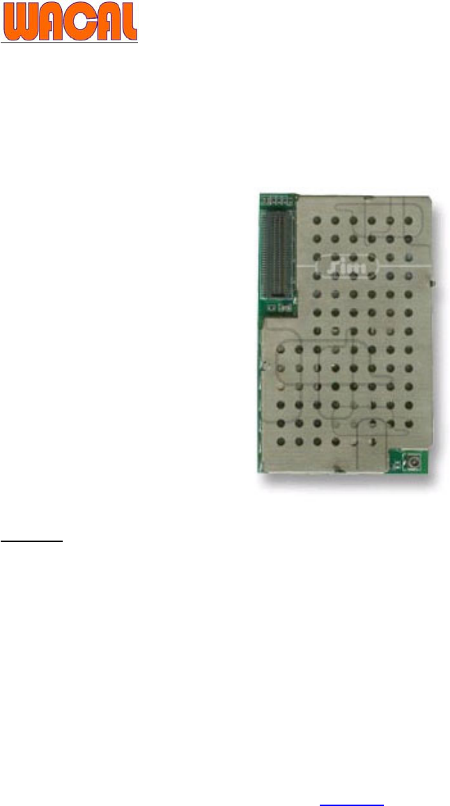
iTrac is designed with GSM and GPRS tracking unit. All options on the iTrac unit can be updated
using GPRS or direct connection with USB data cable, control output by sending an SMS
message or use remote controller.
Features:
SMS, GPRS
Support TCP/IP
Support 16 GPS channels “all in view” tracking
User password management
Battery Backup
Warning alarm on low battery(default <11.5V)
I/O circuit protection
Remote control
II. Getting Started
Warning
FCC regulations state that:
1. The Grantee of a license has the responsibility of assuring that all equipment operated
under that license confirms to the specifications of the license.
2. The RF power output of a radio transmitter shall be no more than that required for
satisfactory technical operation considering the area to be covered and local
conditions.
3. The frequency, deviation, and power of a radio transmitter must be maintained within

3
specified limits. It is recommended, therefore, that these three parameters be checked
before the station is placed in service.
REMEMBER
The efficiency of the equipment depends upon a good installation. Telstar recommends that
adjustments to this equipment be made ONLY by a certified technician.
CAUTION
Changes or modifications not expressly approved by the party responsible for compliance could
void the user's authority to operate the equipment.
The equipment accessories are approved by FCC and only accessories from Telstar Telecom
Inc. are qualified for this equipment applications. Detail information see FCC part 15.27.
IMPORTANT
(a) Only shielded cables, antennas, and special connectors from Telstar Telecom Inc. can be used
in this system. Information detailing any alternative method used to supply the special
accessories shall be must be approved by FCC and included in the application for a grant of
equipment authorization or retained in the verification records, as appropriate. The party
responsible for the equipment shall ensure that these special accessories are provided with
the equipment. The instruction manual for such devices shall include appropriate
instructions on the first page of the text concerned with the installation of the device that
these special accessories must be used with the device. It is the responsibility of the user to
use the needed special accessories supplied with the equipment.
(b) If a device requiring special accessories is installed by or under the supervision of the party
marketing the device, it is the responsibility of that party to install the equipment using the
special accessories. For equipment requiring professional installation, it is not necessary for
the responsible party to market the special accessories with the equipment. However, the
need to use the special accessories must be detailed in the instruction manual, and it is the
responsibility of the installer to provide and to install the required accessories.
(c) Accessory items that can be readily obtained from multiple retail outlets are not considered to
be special accessories and are not required to be marketed with the equipment. The manual
included with the equipment must specify what additional components or accessories are
required to be used in order to ensure compliance with this part, and it is the responsibility of
the user to provide and use those components and accessories.
(d) The resulting system, including any accessories or components marketed with the equipment,
must comply with the regulations.

4
IMPORTANT INFORMATION
(FCC Part 15.105)
This equipment has been tested and found to comply with the limits for a Class B digital
device, pursuant to Part 15 of the FCC Rules. These limits are designed to provide reasonable
protection against harmful interference in a residential installation. This equipment generates,
uses and can radiate radio frequency energy and, if not installed and used in accordance with the
instructions, may cause harmful interference to radio communications. However, there is no
guarantee that interference will not occur in a particular installation. If this equipment does
cause harmful interference to radio or television reception, which can be determined by turning
the equipment off and on, the user is encouraged to try to correct the interference by one or more
of the following measures:
-- Reorient or relocate the receiving antenna.
-- Increase the separation between the equipment and receiver.
-- Connect the equipment into an outlet on a circuit different from that to which the receiver
is connected.
-- Consult the dealer or an experienced radio/TV technician for help.
Start Operation:
1. Plug in the USB data cable in both computer and iTrac. Go to device manager and click
"COM and LPT" to see which comport the USB data is in (example: got comport 8)
2. Plug in the USB smart driver and see which two com port is generated (example got comport
5 & 6)
please change COM5,COM6 and COM8 baud rates to 4800.
A. Double click “Prolific USB-to-Serial Comm Port (COM5)”
B. Select COM Setting icon and change it’s baud rate to 4800 and "flow control (F)" to "Non"
Repeat the step to change COM6 and COM8 baud rate setting
3. Turn on iTrac power, the LED for USB set up would be ON then enter into the software. A
window will appear with red crusor.
4. Go to ITrac+ on the tool bar of the software
Output port 1(pink): OFF Æ deactive ; ON Æ active
N.B. please note that for safety reasons, when send command Output 1(immobiliser) ON the
immobilising effect can only direct activated when ACC is OFF! Or immobilising active after ACC
turned OFF
Output port 2(blue): OFF Æ deactive ; ON Æ active
Remote Controller: Disable Æ remote control disable ; Enable Æ remote control enable
Remote Control With Mobile Phone: Disable Æ can’t control unit use mobile phone

5
Enable Æ can control unit use mobile phone by send text message
(command code) to iTrac.
Arm: OFF Æ disarm ; ON Æ arming.
When arming mode, NO real time data send back to base(stop send data position).
NOTE: At ARM mode when input 1 or input 2 is activated, output 1 will automatically be triggered.
Data Sends through GPRS: Stop Æ unit stop send data use GPRS ; Go Æ Unit send data use GPRS
Data Sends through SMS: Stop Æ unit stop send data use SMS ; Go Æ Unit send data use SMS
Restart: restart iTrac
Get Current Position: request current position, speed and course
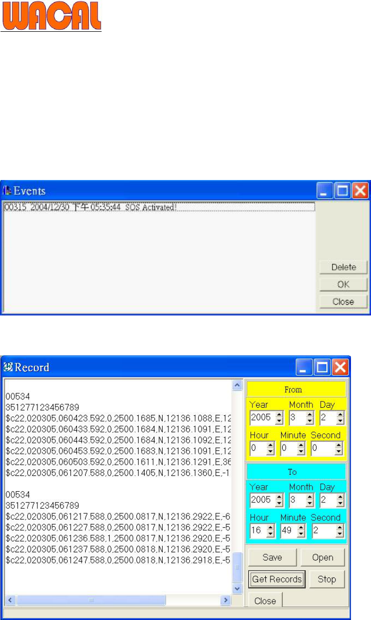
Events
Warning alarm shown in “Events” when one of “SOS, low battery, input 1, input2 have been activated”
Records
Get Records from iTrac memory
III. Upgrade iTrac with new OS

6
For iTrac OS V1.0 or higher allow upgrade it’s OS firmware use USB cable
How to know your current iTrac OS version
1. Enter to “USB SETUP mode”
2. open hyperterminal with 4800 8-N-1
3. enter code C18 and press enter, eTrac will show you its current OS version
Please check the "PC board number"
If the number appears to be "931001D2" please use the "ITrack5a_V12.upd" file to upgrade
if the number appears to be "931001D1" please use the "ITrack5_V12.upd" file to upgrade
you can find it on our ftp site
In order to upgrade the firmware, you have to down load the latest iTrac software V3.201 "SBoxServer050408" or
higher. you can also find the file on our ftp site
Please follow the steps below to upgrade the firmware
1. Extrac and install the file
2. A short cut "SboxServer3.101.exe"will appear on the desktop
3. open the file and get into USB mode (as what you would do when you try to configure iTrac at the start)
4. Go to "Command" on the tool bar
5. Click "update firmware" in the command window
6. Select the appropriate firmware file according to your PC board number and click open
7. Click "Yes" to send the updated firmware to the unit
8. Update should finish in less than 2 minutes
IV. GPRS Data Setup and Operation
It is very important to understand the basic operation of GPRS network and how the data is sent.
We suggest you to check with your GSM service provider for the charges and availability of
GPRS data transfer. Charges for sending data are different in every country in the world.
For sending data we use TCP/IP protocol. This protocol uses complete handshaking (No data
can get lost or corrupted while sending).
It is very cost effective to send data with GPRS as 10,000 bytes of data will only cost about 10
cents, but sending 1 text message (only 160 bytes) will cost about 20 cents (cost depends on
country and GSM service provider). GPRS is more than 124 times cheaper than using SMS
messages!
i. Before you can use GPRS
Before you can use GPRS you need to find out from your GSM provider the following
information:
1. ISP login and password name.
2. APN(Access Point Name)
If GPRS is not available by your GSM provider than enable SMS only.
V. Command Activation Codes and Data Format
When iTrac receives SMS messages it will only accept messages that come from the 1st mobile
phone number preset in call parties.
Note: it needs a space between c1 and x; c2 and x; c3 and x; c5 and x

7
Functions and options that can be set remotely by text messages(SMS)!
iTrac only listens command code that comes from the 1st preset number in Called parties for the
following cases and confirm message will be sent back after one below command codes
c1 x Æ ( x=0 Output 1 OFF
x=1 Output 1 ON)
c2 x Æ ( x=0 Output 2 OFF
x=1 Output 2 ON)
c3 x Æ ( x=0 Remote Controller Disable
x=1 Remote Controller Enable)
c5 x Æ ( x=0 Arm OFF
x=1 Arm ON)
c8 Æ Reset
a confirm message will be sent back to 1st preset number after one of command codes above send
successful to unit.
Ex: c1ok
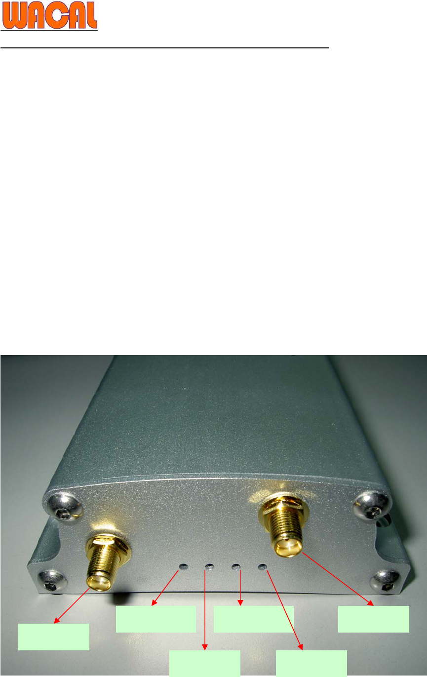
VI. iTrac LED status Indication
GSM LED1 GPS aerial
GSM aerial
GSM LED2
GPS LED USB LED

8
Please Check your iTrac GPS Chipset at PCB:
With FORMAX GPS module
GSM LED1 status Functions
90 ms ON/ 180 ms OFF (quick
flash) No SIM card present / No PIN entered / Network login
in progress
90 ms ON/ 3 sec OFF (slow flash) GSM connected
GPS LED status Functions
90 ms ON/ 90 ms OFF (quick
flash) No GPS satellite signal received
ON GPS ready
GSM LED2 status Functions
ON No SIM card present / No PIN entered / Networl login
in progress
OFF GSM connected and start to use
USB LED status Functions
OFF No USB connected
ON USB connected, enter USB setup*
When the unit is in USB status, GSM is offline.
*To enter USB status: Must connect USB data cable to iTrac before power ON
With NEMERIX GPS module
GSM LED1 status Functions
90 ms ON/ 180 ms OFF (quick
flash) No SIM card present / No PIN entered / Network login
in progress
90 ms ON/ 3 sec OFF (slow flash) GSM connected
GPS LED status Functions
90 ms ON/ 90 ms OFF No GPS satellite signal received
30 ms ON/ 90 ms OFF GPS ready
GSM LED2 status Functions
90 ms ON/ 90 ms OFF GPRS login in progress
OFF GPRS connected and start to use
USB LED status Functions
OFF No USB connected
ON USB connected, enter USB setup*

9
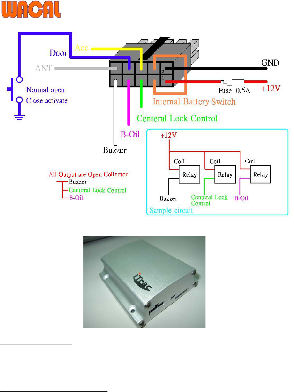
VII. iTrac Connections
Red Æ +12Volt ONLY –input power for the unit must be in the range of +9 to +24 volts for the unit to
operate correctly. A direct connection to the vehicles fuse box is preferable. There is a fuse in this
cable to protect the +12 volt input on the unit.
Black Æ Earth –connected to car chassis ground
Orange Æ Internal Battery Switch
Yellow (input 1) Æ ACC, connect to ground, active when High
Blue(Input 2)Æ Door, connect to ground, active when Low
When input 1 or input 2 is activated, output 1 will automatically be triggered only if ACC is off.
Pink(Output 1)Æ B- Oil, connect through a relay (500mAmp) to fuel pump.
Green(Output 2) Æ Central Lock Control, connect through a relay (500mAmp) to open car doors
White Æ Buzzer
Gray Æ ANT
VIII. iTrac Main Connector Pinout

10
IX. Technical Specifications (Main Unit)
The GPS and GSM modules are integrated inside the tracking unit case.
Physical Characteristics:
Unit size: 95L * 89W * 35H (mm)
Weight: 300 g
Aluminium
Interface: 2 I/Os, 1 Mini USB port, 4 LED lights for GPS,GSM and USB status
Case Environmental Characteristics:
Operational Temperature: -35C to +75C (board temperature)
Storage Temperature –45C to +90C

11
Electrical Characteristics:
GSM: 900/1800 or 850/1800/1900
Input Voltage: + 12V DC
Power Consumption: Standby: 12 Volt – 20 mA ; 12 Volt – 30 mA (Peak)
Transmitting: 12 Volt – 100 mA ; 12 Volt – 130 mA (Peak)
Backup Battery: Rechargeable Li Battery at 1000 mA
Backup Battery life: 6 Hours with GPS and Communication ONLINE -- Depends on battery age, last
charge, approximate only
Memory Backup: Flash Memory 1MB (1000000 * 8 Bits data)
Up to 10000 individual locations can be saved
Two negative outputs (200mA max per output).
Two inputs (active low/high to activate input).
Detects external power loss.
* Power input protected against wrong connection and voltage >24 Volt
* All Inputs are protected against high voltage
GPS Specifications:
Frequency L1, 1575.42 MHz
GPS gain: -152 dbm
Protocol: NMEA0183
Channels 16 Accuracy
Position 25 meters CEP without SA
Hot start <10 sec., average
Warm start <38 sec., average
Cold start <45 sec., average
Remote Controller
Remote controller frequency: 434Mhz
GPS / GSM Antenna Specifications:
GAA11
MGA300 / CH621