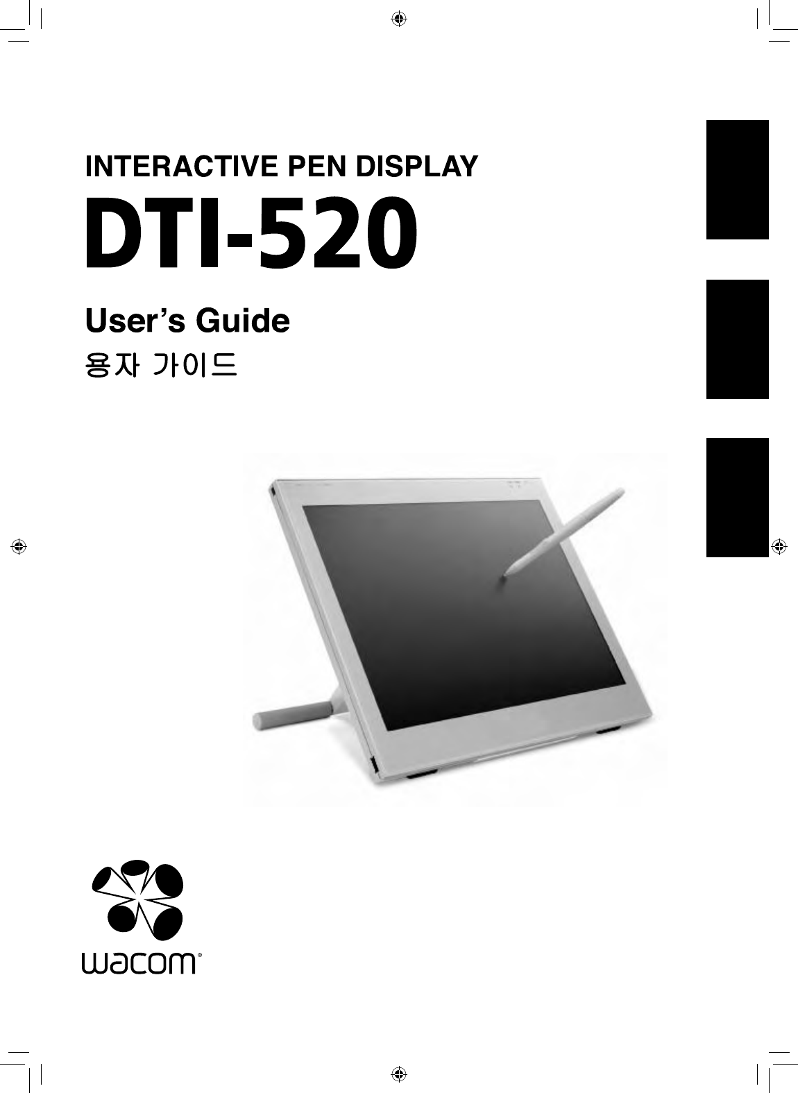
Wacom Dti 520 Users Manual
DTI-520 to the manual 4ec88758-d9af-4763-af5f-973c999f8d04
2015-02-02
: Wacom Wacom-Dti-520-Users-Manual-454136 wacom-dti-520-users-manual-454136 wacom pdf
Open the PDF directly: View PDF ![]() .
.
Page Count: 36
使用手冊
使用手冊
User's Guide
끤녋閻넯麗
DTI-520(A)_1-4.indd 1 2007/11/12 13:49:11
Safety Precautions
■Regarding the power plug and power
adapter.
-Please remove dust from the power
plug regularly. The addition of moisture,
etc. to accumulated dust may lead to
fire.
-Please do not use any power adapters
other than those included with the
product. Ignoring this warning may
result in fire or product failure.
-Please do not damage or forcibly bend
or bundle the power adapter cord. Also,
please do not place heavy objects on it
or expose it to excessive heat. Ignoring
this warning may result in fire, electric
shock or product failure.
-In the unlikely case that the power
adapter should produce smoke or a
strange odor, please disconnect it from
the wall outlet and return it to either the
store where you purchased it or to the
Wacom office in your region for repair
service.
-Please do not connect or disconnect
the power adapter with wet hands.
Ignoring this warning may result in
electric shock or malfunction.
-Please do not open or otherwise
change the power adapter. Ignoring
this warning may result in fire or
electric shock.
prevent this, when in such locations,
always disconnect the product’s USB
connector from your computer and turn off
the switch.
■Do not open the back cover.
Inside this product there are several
high-voltage parts. Persons other than
professional service personnel should
never open the back cover of this product.
Unauthorized opening of the back cover
may lead to fire or electric shock.
■When this product ceases to operate
normally due to being dropped or a
similar cause, remove the power source
cable from the electrical outlet.
Leaving the power cable connected may
result in fire or electric shock.
This product may cause other electronic
devices to malfunction, or other devices
may cause this product to malfunction.
■Turn this product off in places where
the use of electronic equipment is
prohibited.
In airports, hospital intensive care units
and other such places where the use of
electronic equipment is prohibited, this
product may adversely affect the operation
of other electrical devices. In order to
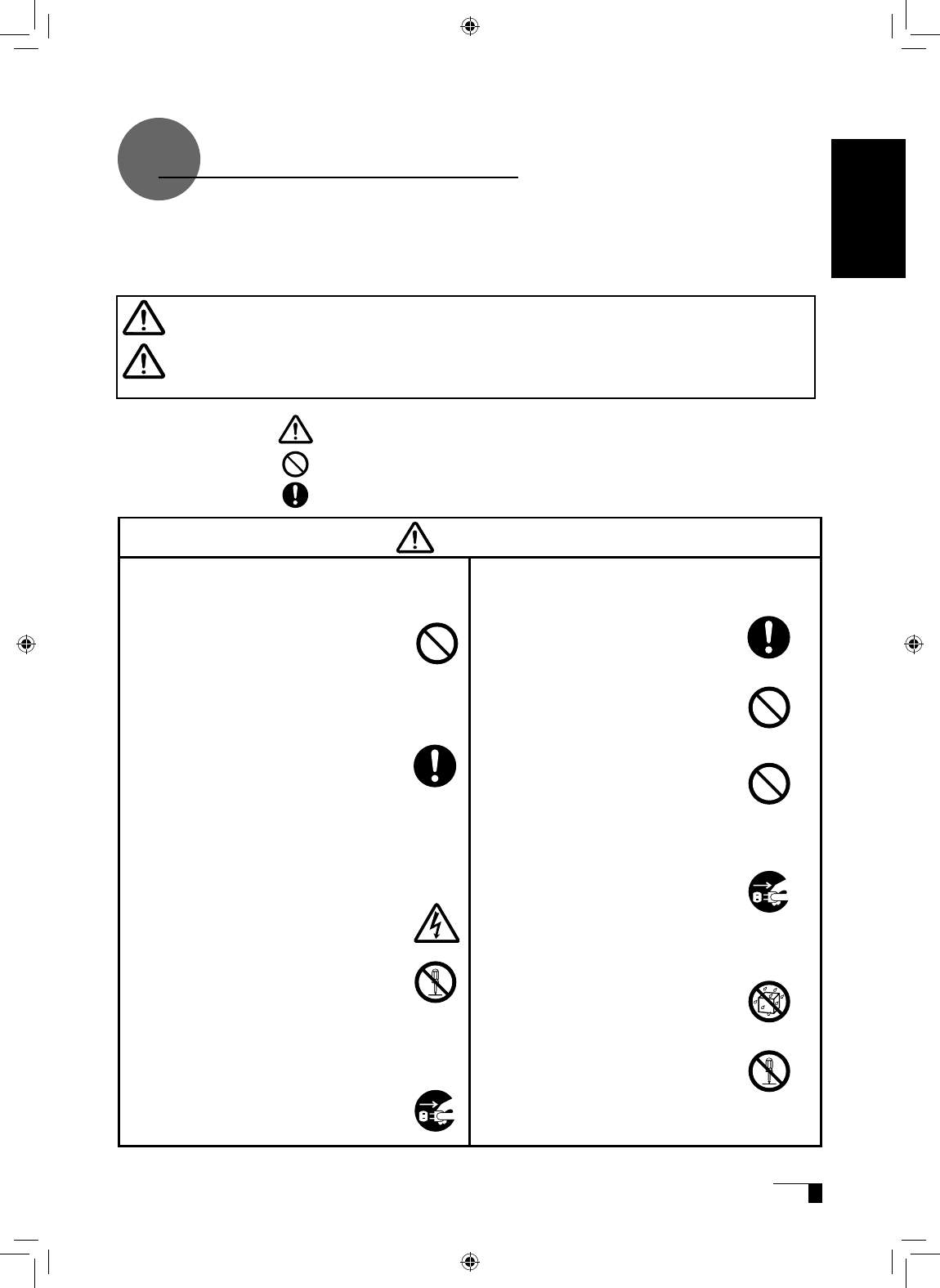
The following symbols appear throughout this user guide in order to ensure safe use of the
DTI-520 (hereafter referred to as “DTI-520,” “the product” or “this product”). Please read these
items carefully and always heed the Warning and Caution items when using your DTI-520.
This symbol indicates an item that, if ignored when handling the product,
could lead to the loss of life or serious injury.
Warning
This symbol indicates an item that, if ignored when handling the product,
could lead to injury or damage to personal property.
Caution
Meanings of Symbols:
Indicates that it is important to be careful when taking the action or actions noted.
Indicates that the action or actions noted are to be avoided.
Indicates it is important to take the action or actions noted.
Warning
■Do not use the product in a facility
control system that requires an
extremely high level of reliability.
User's Guide
UM-0314(A)_EN.indd 1 2007/11/12 16:53:08
of time, disconnect the power adapter
from the electrical outlet.
■Do not use this product in a dusty
environment.
Dust can cause damage to the product.
■Do not block the ventilation holes on
the backside of the product.
Blocking these holes may cause internal
overheating and subsequent damage.
■Do not pick up the product by its stand.
If excessive force is used in handling the
stand, its open and close function may
become damaged. When picking up the
product, always pick it up by the body.
■When connecting the power plug
When plugging the power adapter into an
electrical outlet, also connect a grounded
wire.
■When not using this product for a long
period of time
For safety reasons, when you will not be
using the product for a considerable length
■Do not use organic solvents to clean
this product.
When cleaning the product, never use
such organic solvents as alcohol. Such
solvents may cause discoloration and
deterioration in quality.
■When cleaning this product, always
disconnect the USB connector.
When cleaning the product, always
disconnect the USB connector from the
USB port of the computer. Failure to do so
may result in electric shock.
■While this product is in use, avoid
placing any metal objects on it.
Do not place any metal objects on the
product while you are using it. This may
result in malfunction or product failure.
■Do not touch any liquids that may be
leaking from this product.
The liquid contained in the product is an
irritant. In the unlikely case that such liquid
should leak, never touch it with bare hands.
In case of contact with skin, mouth or eyes,
rinse immediately with running water and
continue rinsing for 15 minutes or longer.
Also consult a physician.
■Do not use excessive force with the cable.
Please do not step on, or place heavy
objects on any of the product’s cables.
Also, do not apply excessive force to the
base of the cable or repeatedly bend and
stretch it, as this may cause it to break or
malfunction.
■Do not place the product in either very
hot or very cold places.
Do not place the product in very hot (35
degrees centigrade or more) or very cold
(5 degrees centigrade or less) locations.
Also, avoid placing it in locations with
severe temperature fluctuations as this
may adversely affect the product and
cause product failure.
■Do not disassemble the
product.
Do not disassemble or modify the
product, as these actions may
lead to fire, excessive generation
of heat, electrical shock or injury.
The guarantee on the product
will become null and void if the
product is ever disassembled.
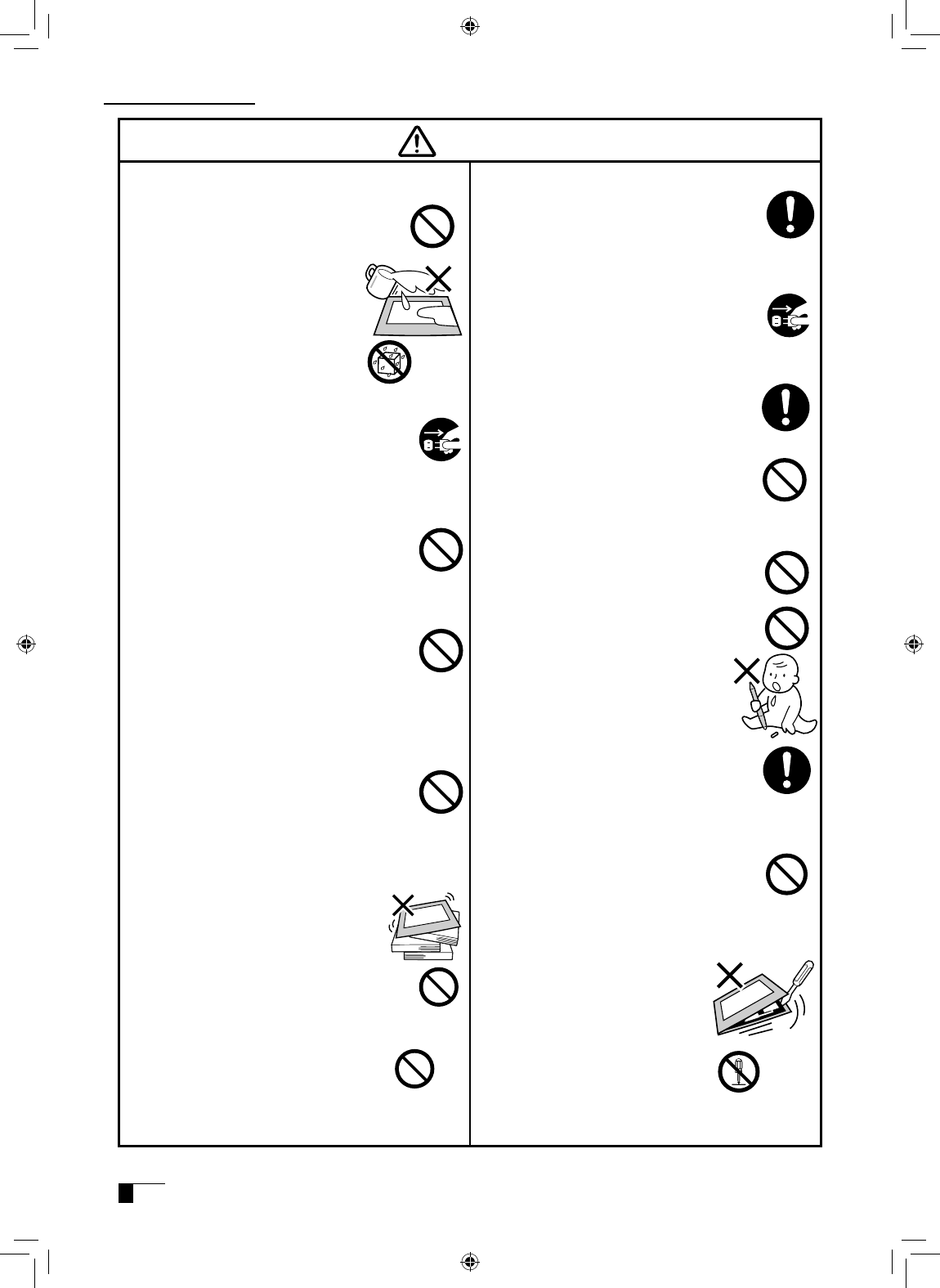
Caution
Safety Precautions
■Do not let the product get wet.
Please do not place containers
such as cups and vases containing
water near the product. Coming in
contact with water or other liquids
may cause product failure.
■Regarding the Pen
-Do not strike hard objects with the
Pen. Doing so may cause damage to
the product.
-Be careful to not allow small children
to put either the pen or the spare nib
into their mouths. There is the danger
that the nib or side switch may be
accidentally swallowed or that the grip
pen may be damaged.
■Do not place the product on
unstable surfaces.
Do not place the product where it is
likely to totter, lean or be exposed
to strong vibrations. Doing so may
lead to the product falling, resulting in
injury and/or product failure.
■Do not place heavy objects
on the product.
Do not put excessive weight, or place
heavy objects on the product. These
actions may cause product failure.
UM-0314(A)_EN.indd 2 2007/11/12 16:53:09
Caution
■Do not connect or disconnect any cable while the product or your
computer is on.
Do not connect or disconnect any cable (including the USB cable) or the power
adapter while your computer or this product is turned on. This may cause damage
to the product or to your computer.
User's Guide
UM-0314(A)_EN.indd 3 2007/11/12 16:53:09
1 Wacom Company, Ltd. holds the copyright to
the auxiliary tablet.
2 The unauthorized duplication or reproduction in
whole or in part of the tablet driver or this user
guide is expressly prohibited.
3 Wacom reserves the right to change the
configurations or specifications of the tablet
driver or the product, as well as the contents of
this user guide, without prior notice.
As a participant in the Energy Star program,
Wacom has determined that this product meets
the standards of the Energy Star program.
Please take the following precautions
to protect the health of your eyes.
●When using the product, make sure that the
room is sufficiently illuminated and be careful
not to get your face too close to the screen.
●Take regular breaks when using the product
over an extended period of time.
Warranty Exclusions
Regarding warranty of the product
Wacom warrants the product, to the original
consumer purchaser, except software, to be free
from defects in materials and workmanship under
normal use and service as long as the product
remains in production, but not less than one (1)
year, from the date of original retail purchase,
as evidenced by a copy of the receipt or online
registration with Wacom within 30 days of purchase.
Regarding Trademarks
●Windows is a trademark of Microsoft
Corporation, registered in the United States
and other countries.
●Macintosh is a trademark of Apple Computer,
Inc., registered in the United States.
●Other product names and related items are
the trademarks or registered trademarks of
each concerned company.
Precautions
Depending on what is being displayed, bright or
dark green, red and blue dots may show up on
a very small portion of the LCD display screen.
These do not indicate product failure or a lack of
quality.
Safety Precautions
●Wacom will not bear any responsibility
for damage caused by fire, earthquake,
accidents caused by third persons, intentional
or accidental abuse by the customer or any
other damage caused by abnormal use of the
product.
●Wacom will not bear any responsibility for
contingent damages (such as loss of business
profits, suspension of operations, alterations
to and disappearance of data, etc.) caused by
use of, or inability to use, this product.
●Wacom will not bear any responsibility for
damage resulting from the use of this product
in a fashion other than as explained in this user
guide.
●Wacom will not bear any responsibility for
damage resulting from malfunctions caused
by using this product in conjunction with
adaptation equipment or other company’s
software.
Regarding this User Guide
This user guide contains instructions regarding
the set up, installation, functions and methods
of use of this product. The product consists of
the LCD monitor and the tablet, which will act
as two distinct pieces of equipment to be used
in conjunction with your computer. First, you will
set up the display device and then you will install
the tablet driver in your computer. You will then
be able to use this product as a built-in display
tablet.
Analog RGB compatible video output is
necessary for the screen display of this
product. For information regarding how to use
video cards, refer to the instruction manual
accompanying the video card.
Please be aware of the following
regarding the LCD display.
UM-0314(A)_EN.indd 4 2007/11/12 16:53:10

Table of Contents
Safety Precautions... ................................................................. 1
Table of Contents ...................................................................... 5
Component Functions ............................................................... 6
Opening the Stand ......................................................................................................7
Using the Penholder ...................................................................................................7
Installing DTI-520 on a Mount Arm .............................................................................8
Accessory Check....................................................................... 9
Connecting DTI-520 ............................................................... 10
Installing the Tablet Driver ...................................................... 12
Windows Setup .........................................................................................................12
Macintosh Setup .......................................................................................................12
Uninstalling the Tablet Driver ....................................................................................12
The DTI-520 Display ................................................................ 13
Switching Display Images .........................................................................................13
The Auto-Adjust Function .........................................................................................13
The DTI-520 Power Saving Function ........................................................................13
Blurring and Protrusion of the Picture from the LCD Panel... ...................................14
On-Screen Display (OSD) Menu ...............................................................................15
Using the OSD Menu ................................................................................................15
Pen ......................................................................................... 18
Basic Operations of the Pen .....................................................................................19
Using the Control Panel .......................................................... 20
Displaying the Control Panel .....................................................................................20
Control Panel Basics .................................................................................................20
Synchronizing the Positions of the Pen Tip and Pointer ...........................................23
Using Multiple Interactive Pen Displays .................................. 24
Supplementary Information ..................................................... 25
Removing Stains .......................................................................................................25
Replacing the Pen Nib ..............................................................................................25
Attaching the Pen Tether ...........................................................................................26
Troubleshooting ...................................................................... 27
Display Troubleshooting ............................................................................................27
Pen Troubleshooting (For Both Windows and Macintosh) ........................................29
General Troubleshooting ...........................................................................................29
Troubleshooting for Windows ...................................................................................30
Troubleshooting for Macintosh .................................................................................30
Specification ........................................................................... 31
Warranty ................................................................................. 32
Obtaining Technical Support ................................................. 34
User's Guide
UM-0314(A)_EN.indd 5 2007/11/12 16:53:10
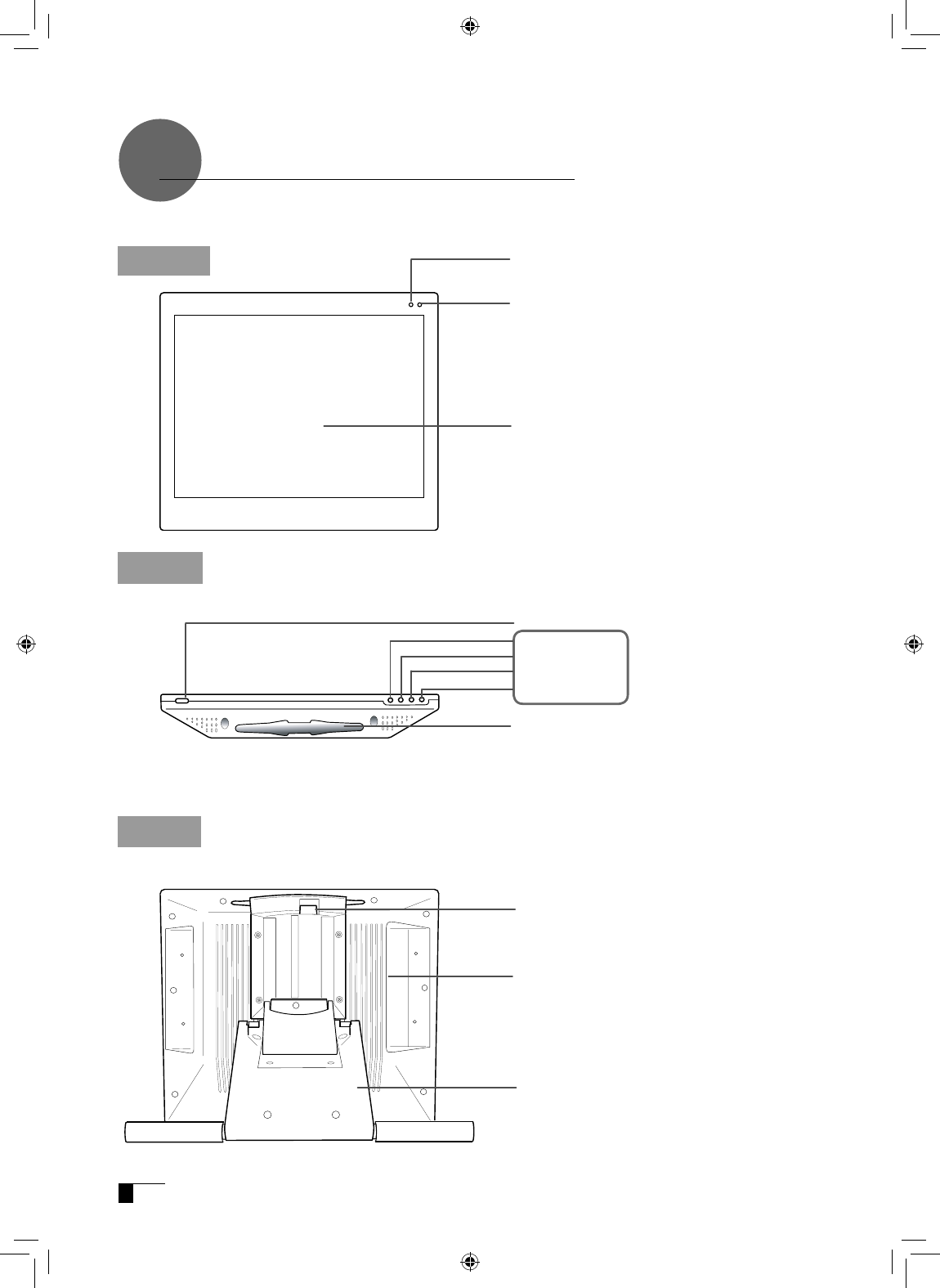
Component Functions
Integrated LCD
Monitor and Tablet
+ Button
- Button
ENTER Button
Menu Button
Stand Adjustment Lever
▶P.7
▶
P.15
Connector
▶P.10-11
Stand
▶
P.7
Top
Power Switch
Pen Rest
Place the pen here while the pen is not in use.
Power LED
Lights blue when power has been supplied the
DTI-520 and the computer and video signals are
present. Glows orange when no video signal is
detected by the DTI-520.
Status LED
When the pen switch is on, this will become blue.
Front
Back
UM-0314(A)_EN.indd 6 2007/11/12 16:53:11
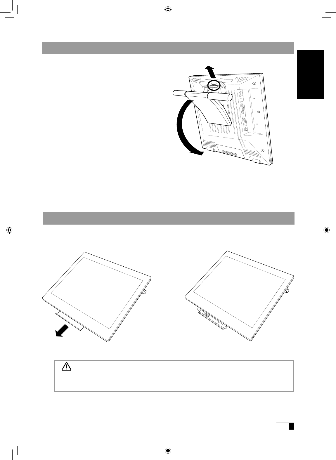
Opening the Stand
1Pull up on the stand adjustment lever.
2Lower the stand carefully.
Using the Penholder
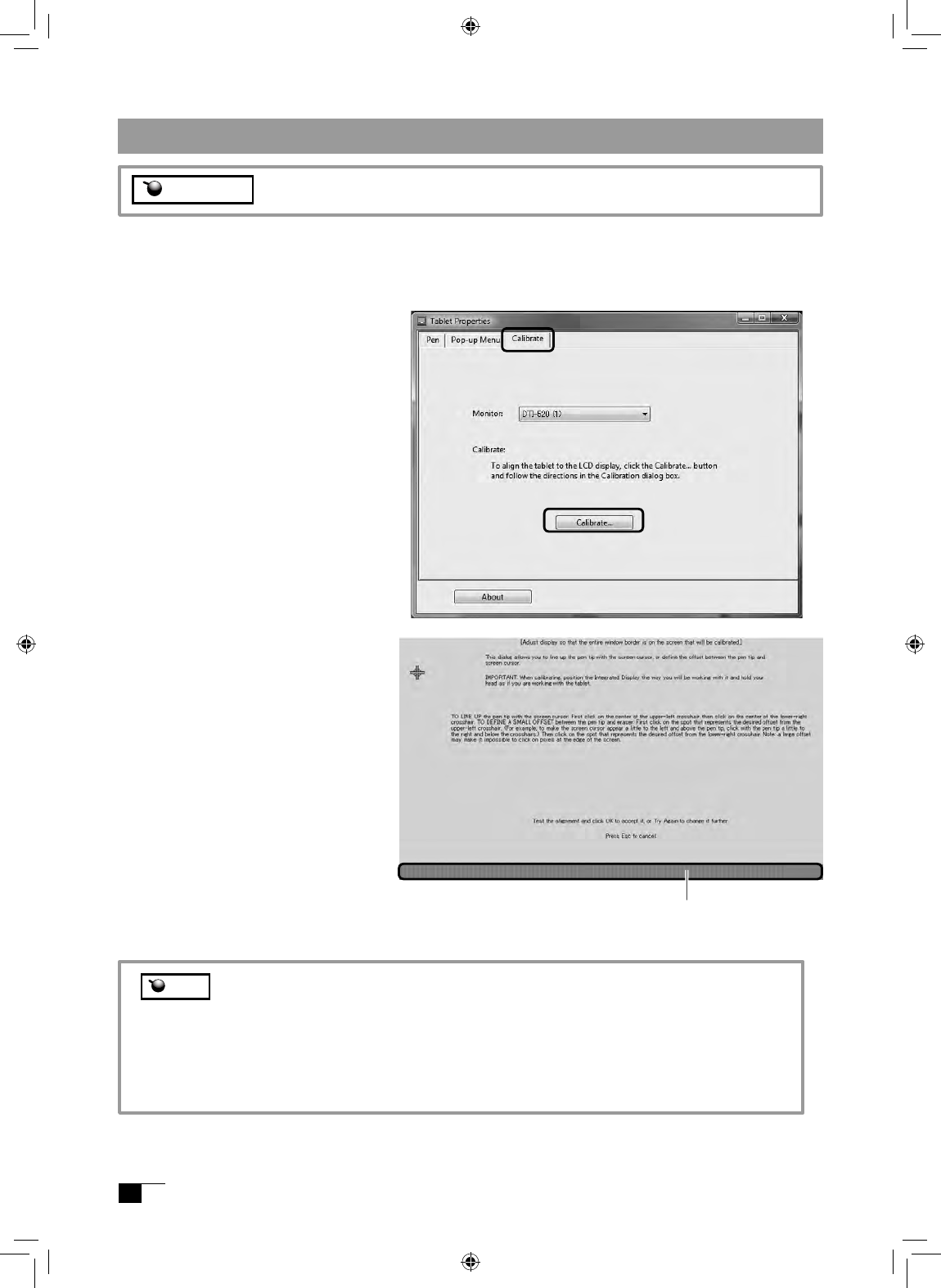
Pull the penholder towards you as shown in the illustration below.
1
2
Caution
Always close the stand and, as shown in the above illustration, lay the tablet on its side
before pulling the penholder out.
User's Guide
UM-0314(A)_EN.indd 7 2007/11/12 16:53:11
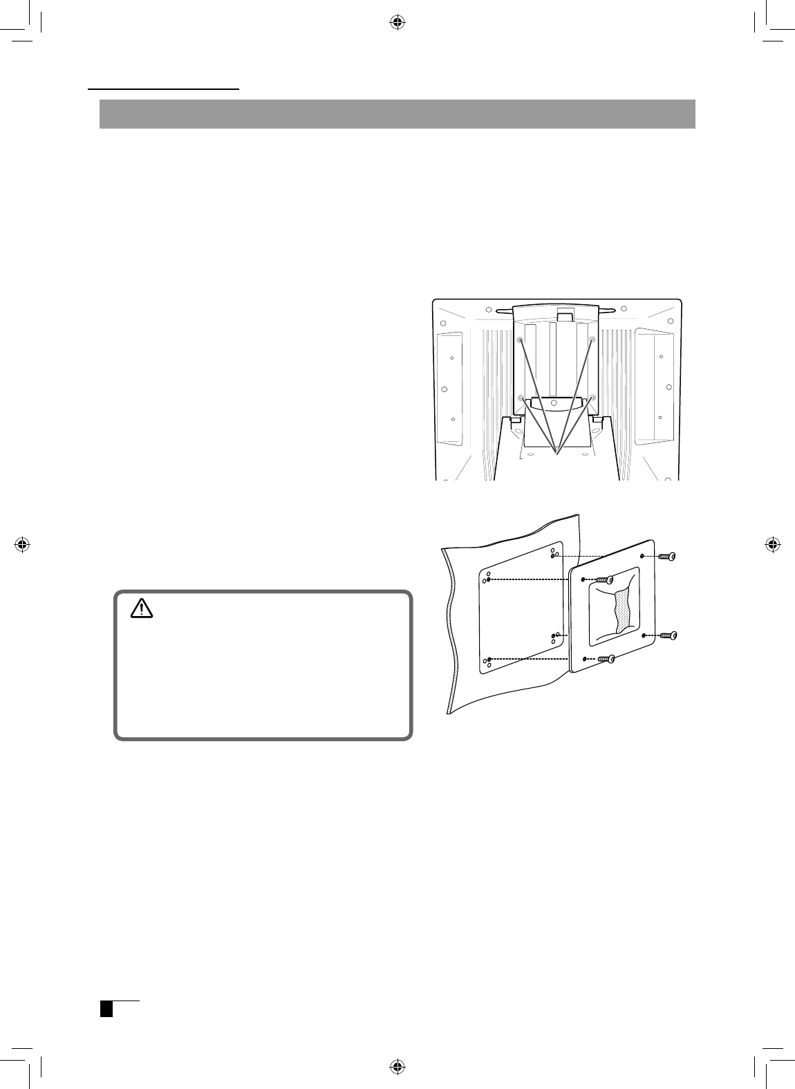
Installing DTI-520 on a Mount Arm
Caution
When installing the unit on a mount arm or
other stand, always follow the directions in
the instruction booklet for the mount arm or
stand, as well as the instructions contained
in this document. Incorrect installation may
result in the product coming loose and falling
and possibly causing product failure.
5Connect the cables and save the screws
that you removed in step 3.
3Remove the four screws that hold the stand
to the unit.
4Using four M4/0.7 mm screws, securely
mount the arm or similar apparatus to the
back of the unit.
2Place the display unit face down on a flat
surface. To prevent harm to the front of
the unit, first spread a cloth or other similar
material on the flat surface.
Unscrew
Component Functions
This product conforms to the Video Electronics Standard Association’s (VESA) Flat Panel
Monitor Physical Mounting Interface Standard (FPMPMI).
This product can be removed from the stand and mounted on such apparatuses as a
VESA-standard mount arm. In order to do this, M4/0.7 mm screws, which are not included
with the product, are needed. Use screws that will, at the time of installation, penetrate the
surface of the product by no more than 15 mm. Use of longer screws may result in damage
to internal parts of the product.
1Make sure that both your computer and the product are turned off and that all cables are
disconnected.
UM-0314(A)_EN.indd 8 2007/11/12 16:53:12
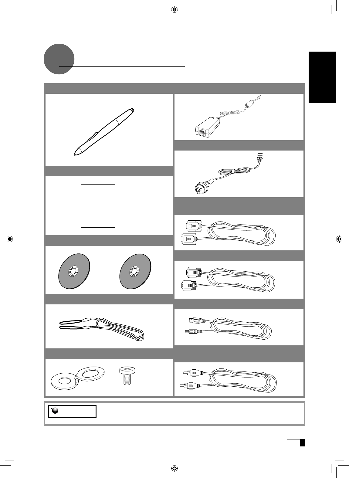
●USB Cable
●Power Adapter
●Power Cable
●Pen
●User Guide (This booklet)
●Serial Cable
*Not included in DTI-520UB model
●Analog RGB Cable
●Composite Video Cable
*Not included in DTI-520UB model
●Pen Tether
User Guide
●
Pen Tether Attachment Fitting / Screw
●
Tablet Driver CD/ Bundled Software CD
Accessory Check
Important Do no throw the box away; it is useful for the storage and transport of the
product.
User's Guide
UM-0314(A)_EN.indd 9 2007/11/12 16:53:13
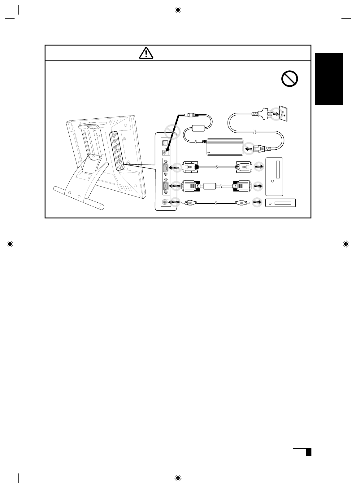
0
1Turn off both your computer and the product.
2Connect the Analog-RGB connector to your computer’s display port.
3Connect the power adapter to the power cable and connect the DC power connector to the
DC power input terminal. Next, plug the power cable into your electrical outlet.
Be sure to also connect a ground wire.
4Turn on the product’s power switch.
The power indicator lamp will light up orange.
5Turn on your computer.
6While looking at the LCD screen, configure the color resolution and size settings.
7Turn off your computer.
When using the tablet with a serial cable connection, the product’s USB hub
function cannot be utilized.
Caution
8Connect the product to your computer using either a USB cable or a serial cable, depending
on which is appropriate for your computer.
For Macintosh, use a USB cable connection.
9Turn on your computer.
10Install the tablet driver (Please refer to “Installing the Tablet Driver” on page 12).
- Do not modify the refresh rate. Setting the rate to a value that exceeds the DTI-520
refresh rate may result in loss of picture.
- The color palette settings and corresponding number of colors displayed are as
follows:
High Color (16 bit) →65,536 colors / True Color (24 bit) → Roughly 16.2 million colors
*The number of colors is limited by the efficiency of your computer and video card.
For details, refer to the user’s manual provided by the manufacturers.
Important
Connecting DTI-520
Please separate the DTI-520 from other tablets or similar devices. Electrical
interference may affect operational quality of the DTI-520.
Caution
UM-0314(A)_EN.indd 10 2007/11/12 16:53:14
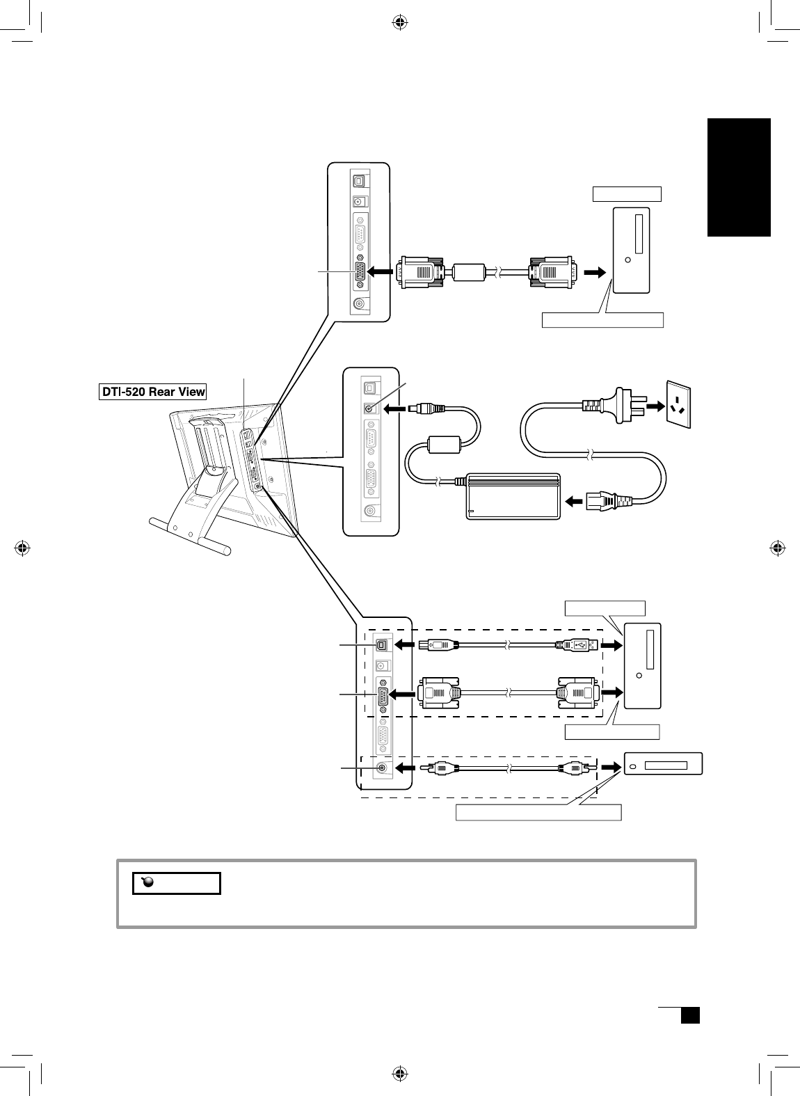
USB connector
ࠪࠕ࡞ࠤࡉ࡞
Connectors Area
Analog RGB cable
Composite video cable
USB cable
Power cable
Power Adapter
DC Power Input Terminal
To analog RGB port
ࠪࠕ࡞ࡐ࠻߳
To USB port
Computer
Outlet
Ground Wire
such as DVD player
Analog RGB
connector
Composite video connector
Composite video connector
Serial connector
Serial cable
To serial port
If necessary, connect them.
Use the connection that is
appropriate for your computer.
Make sure to connect only one
of the cables shown.
(For Macintosh, only a USB
cable connection is possible.)
When using the tablet with a serial cable connection, the product’s USB hub
function cannot be utilized.
Caution
2
3
8
User's Guide
UM-0314(A)_EN.indd 11 2007/11/12 16:53:14
Windows Setup
Before installation, connect the DTI-520 USB cable or serial cable to your computer and turn the unit on.
1First turn on the DTI-520. Then turn your computer on and login, allowing the operating sys-
tem to fully load. The DTI-520 will automatically register as a USB device.
2Insert the DTI-520 tablet driver CD into the CD-ROM drive. The DTI-520 menu should au-
tomatically display. If the menu does not display, double-click on the INSTALL icon (lo-
cated on the CD). Click on the INSTALL PEN TABLET button and follow the prompts
to install the driver software.
Installing the Tablet Driver
Macintosh Setup
1Connect the USB cable to your computer, turn on the product and start up your Macintosh.
2Close any open applications and temporarily turn off any virus-monitoring programs.
3Insert the Tablet Driver CD-ROM into your computer’s CD-ROM drive and open the CD-ROM
and double-click on Install or Install.app.
4Click on Install Wacom Tablet and installation will begin. Thereafter, follow the screen instruc-
tions and continue the installation process.
If during processing, the identity confirmation dialog box displays, input your password *.
5After the tablet driver installation is complete, restart Macintosh.
Uninstalling the Tablet Driver
Hint *After installing OS X, input your password.
Macintosh OS x 10.2 and newer versions include as a standard feature the
Inkwell function. If this function is on, the yellow Inkwell memo pad will appear
after installation of the Tablet Driver. To disable this function, click on Ink from
the Control Panel, click on Settings and remove the checkmark from Allow Me
to Write Anywhere.
Caution
Windows
1Click on the Windows Start button and open the Control Panel. Double click the Programs
and Features icon or the Add and Delete Program (Application) icon.
2
Select Pen Tablet from the list and click the Uninstall or the Modify (Add) and Uninstall or De-
lete button. Follow the instructions in the dialog box to initiate uninstall.
If Windows is restarted, it is deleted.
Macintosh
1
Open the Applications folder and then open the Tablet folder.
2
Start up Remove Tablet and follow the instructions to initiate uninstall.
UM-0314(A)_EN.indd 12 2007/11/12 16:53:14
The DTI-520 Display
* Depending on the specifications and settings of your computer and video
card, when in standby and suspend modes, the power lamp may only light
up orange.
This product is in compliance with VESA and ENERGY STAR power-saving guidelines. When
connected to a Display Power Management (DPMS)-compatible computer and graphics board, the
power savings indicated below are automatically realized during times of non-operation.
Computer
Activity
Horizontal
Synchronizing
Signal
Vertical
Synchronizing
Signal
Picture
Signal
Power
Consumption
Power Lamp
Turned On Yes Yes Yes 23W or less Blue
Stand-by Mode No Yes No Less than 2W Orange/Blue*
Suspend Mode Yes No No Less than 2W Orange/Blue*
Off Mode No No No Less than 1W Orange
The DTI-520 Power Saving Function
Either an image input from the RGB – RGB cable (see P. 11) or an image input from the composite
video cable (see P. 11) will be displayed on the DTI-520. Either of these images can be replaced by
using the following method:
●Switch at the INPUT CONVERSION screen, which can be assessed from the menu screen.( ▶P.17)
●Click on the ENTER button.( ▶P.15)
Switching Display Images
If both the RGB – RGB cable and the composite video cable are connected,
and then you turn the unit on, the image input from the RGB – RGB cable takes
priority and is displayed.
Important
In order to ensure optimal display image quality, this product utilizes the Auto-Adjust function. When
the Auto-Adjust function is operating, it may take a short time before the screen displays properly.
The settings initiated by Auto-Adjust are saved in the display.
If the Auto-Adjust function is operating, the horizontal and vertical positions as
well as the phase and pitch of the display are adjusted automatically when the
display mode is received. The Auto-Adjust function becomes operational when
the horizontal frequency is in the 30-56.5KHz and the vertical frequency is in the
45-75Hz range.(When resolution is 1024 × 768 dot (XGA), vertical frequency is in
the 45-70Hz range)
When the Auto-Adjust function is operating, only the power switch is operational
.
The Auto-Adjust Function
Hint
Caution
Hint
User's Guide
UM-0314(A)_EN.indd 13 2007/11/12 16:53:15
3
Using the OSD controls, open the
OSD Menu and the Pitch icon.
4Adjust the pitch level so the
pattern of fine vertical stripes
display evenly.
5In the OSD Menu, select the
Phase icon.
6
Adjust the phase level so the ad-
jusutment pattern shows clearly.
7After completing these adjust-
ments, press the ENTER and
MENU buttons to exit the OSD
Menu.
8Click on the CANCEL button or
press the ENTER and MENU
buttons to exit the OSD Menu. Adjustment pattern for pitch and phase
Blurring and Protrusion of the Picture from the LCD Panel
Depending on the type of computer and graphics board, the Auto-Adjust function is sometimes not
able to operate at full power, resulting in the picture blurring and protruding from the LCD panel. If
this happens, adjust the pitch and phase. At 1024 x 768-bit, the resolution is optimally adjusted.
Procedure:
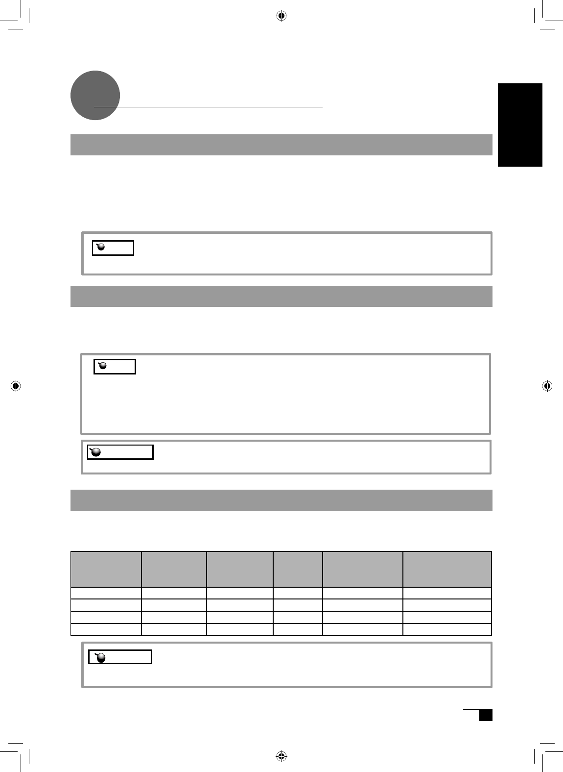
1Open the Tablet Control Panel
(see page 21) and select the
Calibrate tab.
2Click on the Calibrate... button.
An adjustment pattern for pitch
and phase will appear.
1
2
This setting is effective when the product and computer are connected by a
RGB cable.
Hint For Windows 2000, the pitch and phase may be calibrated after the Exit
Windows screen is displayed. If the frequency needs to be calibrated, light
and dark vertical stripes will appear in the dark areas of the screen. If the
tracking needs to be calibrated, light and shade will appear horizontally in the
dark areas of the screen (for 1024 x 768-bit resolution).
This method is recommended in situations where the tablet driver has not
been installed.
Caution
UM-0314(A)_EN.indd 14 2007/11/12 16:53:15
Using the OSD Menu
How to Use the OSD Menu
Example: Adjusting the brightness
1Click on the Menu button to display the Main Menu
Settings screen.
2Click on the + button and the − button and select the items to
be adjusted. When the option you want to adjust is highlighted,
press the ENTER button.
3Use the + and − buttons to adjust numerical values and other
items.
4After making you change, press the ENTER button to save.
5To exit, press the Menu button.
− buttons, + buttons :
You can select an option that can
be activated.After activatng a
selected option, press the + button
to increase a selected item value,
and press the - button to decrease
it.
Menu button :
Opens or closes the OSD
Menu.
ENTER Button
Activates or deactivates the selected OSD
menu option.
Also switches the image input from the RGB
– RGB cable and the image input from the
composite video cable. ▶P.13
On-Screen Display (OSD) Menu Buttons
Adjusting picture quality and setting up the display are accomplished by using on-screen buttons to
establish and change adjustment items and values. Click on the Menu button and the menu screen
appears. Select the items to be adjusted and their desired settings.
The DTI-520 Display
User's Guide
UM-0314(A)_EN.indd 15 2007/11/12 16:53:16
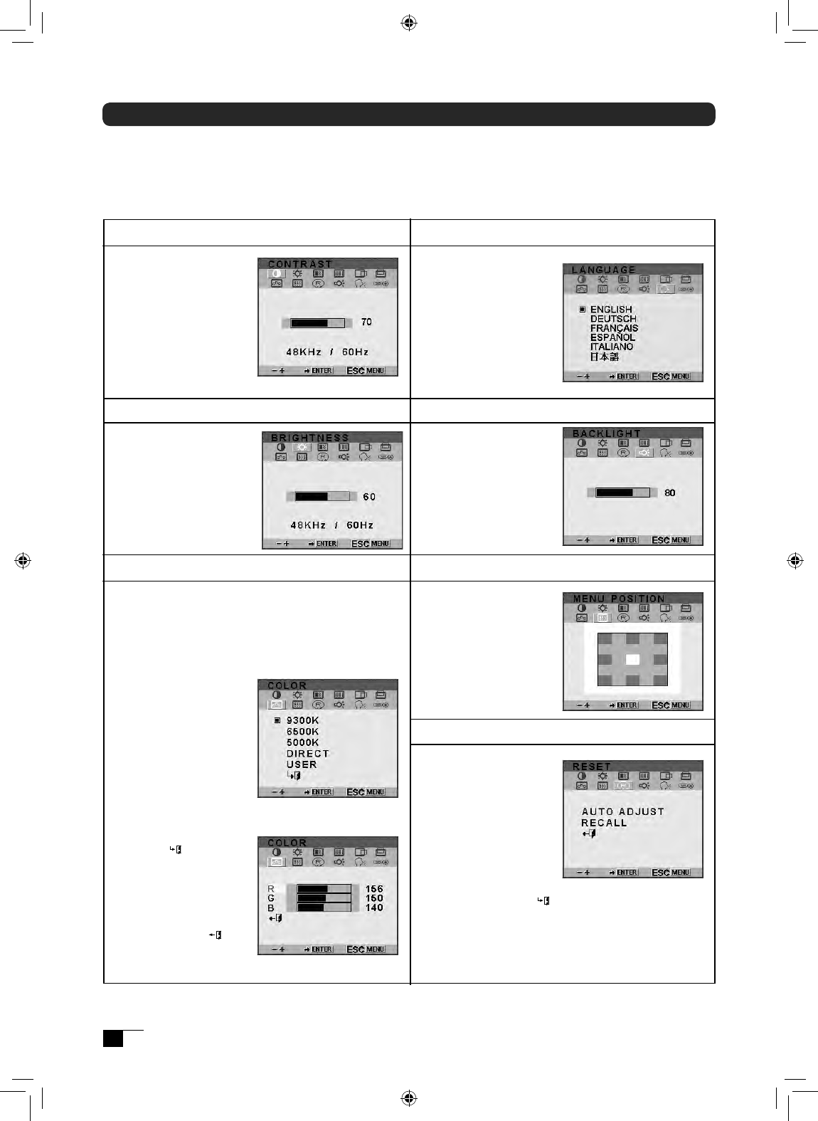
Menu Position
Reset
Brightness
Contrast
Select to increase
or decrease image
contrast.
Caution: Provided
“direct” is selected on
color temperature, it
cannot be changeable.
Types of OSD Menus
Select to increase
or decrease image
brightness.
Caution:
If DIRECT is
selected in the Color
menu, Brightness
cannot be changed.
Select to move the
OSD menu around
the display.
Provides two options:
Use AUTO ADJUST
to reset only the
image parameters.
Use RECALL to reset
all screen options to
the factory default.
Selecting the exit ( )icon exits the Reset
screen without changes.
Color
Backlight
Language
Provides settings for 9300°, 6500°, and 5000°
Kelvin.
Also provides a User option that enables you
to adjust red, blue and green independently.
Selecting DIRECT
displays the received
signal as it is without
any adjustment.
Choose a setting to
work with and press
Enter to activate your
selection. You can
change the user
setting by selecting
the icon ' '.
In the User Adjustment
window, change red,
blue and green to
calibrate color. To exit,
select the icon ' '.
Selects to increase or
decrease the backlight
brightness level.
Select to choose a
language option for
the OSD: English,
Deutsch, Francais,
Espanol, Italiano, or
Japanese.
Some menu screen displays may vary depending on whether a RGB cable or a video cable
is connected. The following screens explained in Common Screens below are the same ones
regardless of the connection method.
●Common Screens
UM-0314(A)_EN.indd 16 2007/11/12 16:53:16
Vertical Center (VGA only)
Horizontal Center (VGA only)
Pitch (VGA only)
Phase (VGA only)
Select to red
uce or
eliminate horizontal
distortion lines.
To automatically
adjust, use the Reset
screen.
Select to reduce or
eliminate vertical distortion
lines.
To automatically adjust,
use the Reset screen.
Select to move the
screen image left or
right.
To automatically
adjust, use the Reset
screen.
Select to move the
screen image up or
down.
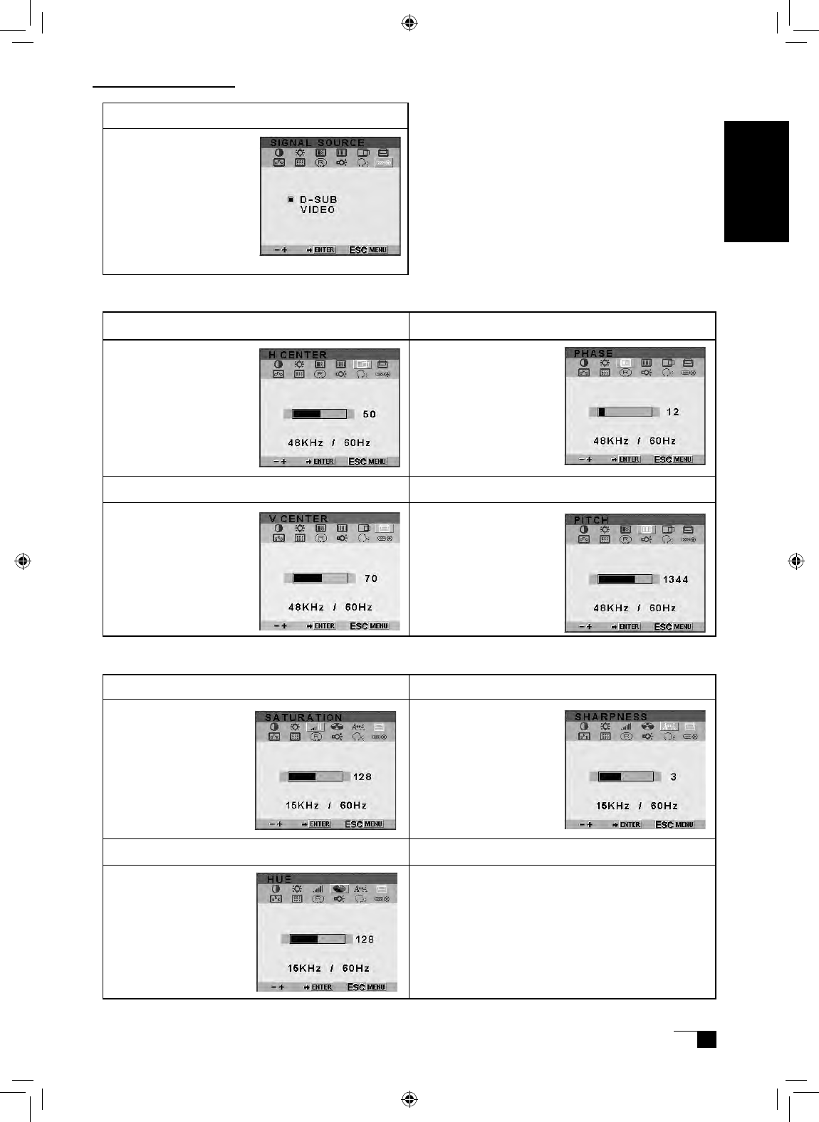
To automatically adjust,
use the Reset screen.
Signal Source
●Screens that Display with a RGB Cable Connection
●Screens that Display with a Video Cable Connection
Saturation Sharpness
Hue
Adjust sharpness of
a image.
Select D-SUB and
the image input from
the RGB – RGB cable
displays.
Select VIDEO and the
image input from the
composite video cable
displays.
Adjust saturation of a
image.
Adjust hue of a
image.
The DTI-520 Display
User's Guide
UM-0314(A)_EN.indd 17 2007/11/12 16:53:17
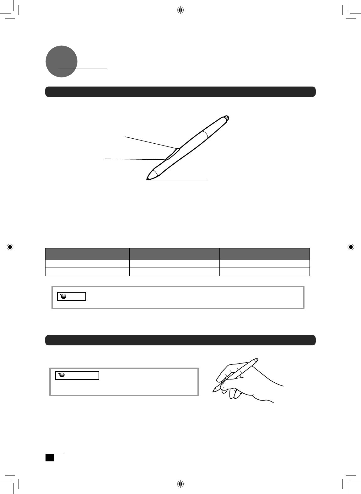
Gripping the Pen
You can hold it just like a pen.
Pen
The Parts of the Pen and Their Functions
With one touch of the second
side switch, functions that have
been previously established
become functional. ▶ P.21-22
Second Side Switch
With one touch of the side
switch, functions that have been
previously established become
functional. ▶ P.21-22
Side Switch
Note See P.20-22 about setting of the side switch and the second side switch.
Caution
Please be careful by mistake not to push a switch.
Pen Tip
• You can change the position of the screen
pointer by moving the tip of the pen.
• By varying the amount of pressure applied,
the boldness of lines and the size of points
can be adjusted.
• If the pen nib shows signs of ware, it can be
replaced. See page 25.
Windows Macintosh
Side Switch Right Button-click Right-click
Second Side Switch Double-click Double-click
Default Switch Function Settings
UM-0314(A)_EN.indd 18 2007/11/12 16:53:17
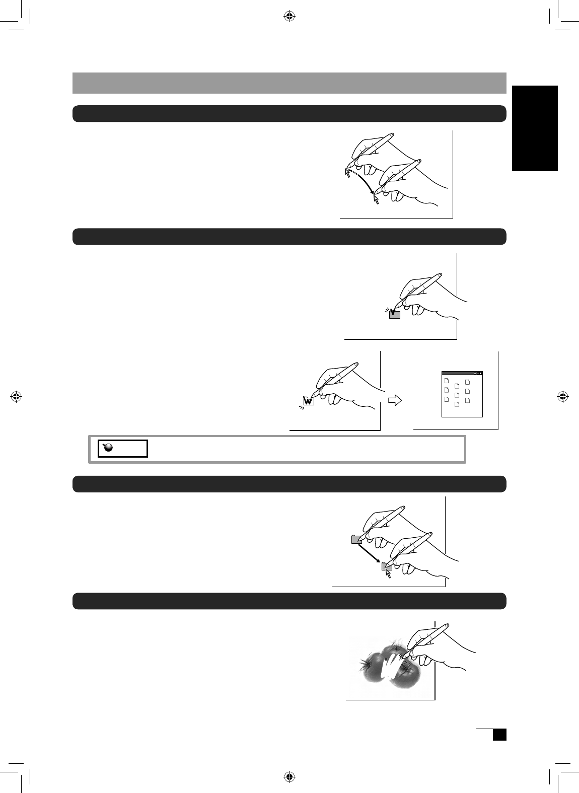
Moving the Pointer
By raising the pen a little above the screen and moving it,
you can move the position of the screen pointer.
Basic Operations of the Pen
Clicking and Double-clicking
Clicking
Tap on the screen lightly once with the tip of the pen to
click.
Note The second side switch is set to double-click as a default setting.
Double-clicking
Tap in the same place twice quickly with the tip
of the pen to double-click.
Dragging
Select an icon or folder and then, while keeping the pen
tip pushed down, move the pen to move the object.
Using the Eraser
By setting the eraser function and then tracing over the
display, pictures and handwritten characters disappear
as if erased by a standard eraser.
User's Guide
UM-0314(A)_EN.indd 19 2007/11/12 16:53:18
0
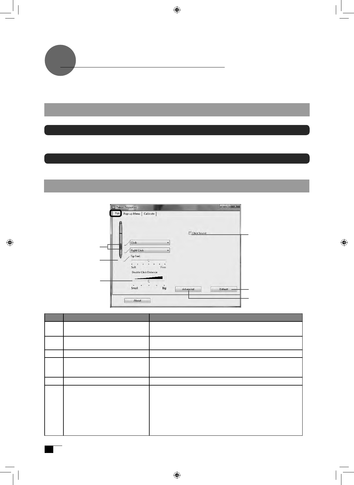
Using the Control Panel
Change the settings for the pen and adjust the pointer and pen tip positions with the control panel.
*When connecting and using multiple tablets, see page 24.
Displaying the Control Panel
Opening the Control Panel in Windows
Click on the Windows Start button, go to All Programs (P) or Programs (P), open Pen Tablet and
select Pen Tablet Properties.
Opening the Control Panel in Macintosh
Open System Settings and then Pen Tablet.
NO Setting Item Description
1The second side switch and
the side switch
Selects the side switch button functions for pens equipped
with a side switch. See page 21-22.
2Tip Feel Customizes the amount of pressure needed to click or draw
with the pen.
3Double Click Distance Adjusts the size of the double-click area. See page 21.
4Click Sound When checked, an audible “click” sound will be heard
whenever a pen click occurs and your computer speakers are
turned on.
5Default Returns the PEN tab settings to their factory defaults.
6Advanced When the Side Switch is set to right click or other click
functions, select one of the following two modes of operation.
・Hover Click: allows you to perform click functions by
pressing the Side Switch when the pen tip is raised slightly
above the active surface.
・Click & Taps: press the Side Switch and then lightly press
the pen tip against the active surface. This is the default
setting for tablet PCs.
1
2
3
5
Control Panel Basics
You select the pen tab.
4
6
UM-0314(A)_EN.indd 20 2007/11/12 16:53:18
Switch and Button Settings
Function Names
Description
Windows Macintosh
Click
Right-Click
Middle-Click
Click
Right-Click
Middle-Click
Performs the same operations as a normal mouse.
4th click(Forward) Simulates a 4th mouse button click, which on Windows systems typically
issues the Forward command in browser applications. Not available on
Macintosh systems.
5th click(Back) Simulates a 5th mouse button click, which typically issues the Forward
command in browser applications. Not available on Macintosh systems
Double-Click Simulates a left mouse button double-click. For easier double-clicking, use
this function instead of tapping twice with your pen.
Click-Lock Simulates holding down the left mouse button. Press the tool button once
to initiate click lock. Press the button again to release click lock. Click lock
is useful for dragging objects or selecting blocks of text.
Pop-up Menu Displays a Pop-up Menu on your screen.
See page 22 for more information.
Erase Works like the eraser on a pencil in graphic applications that support the
Erase function.
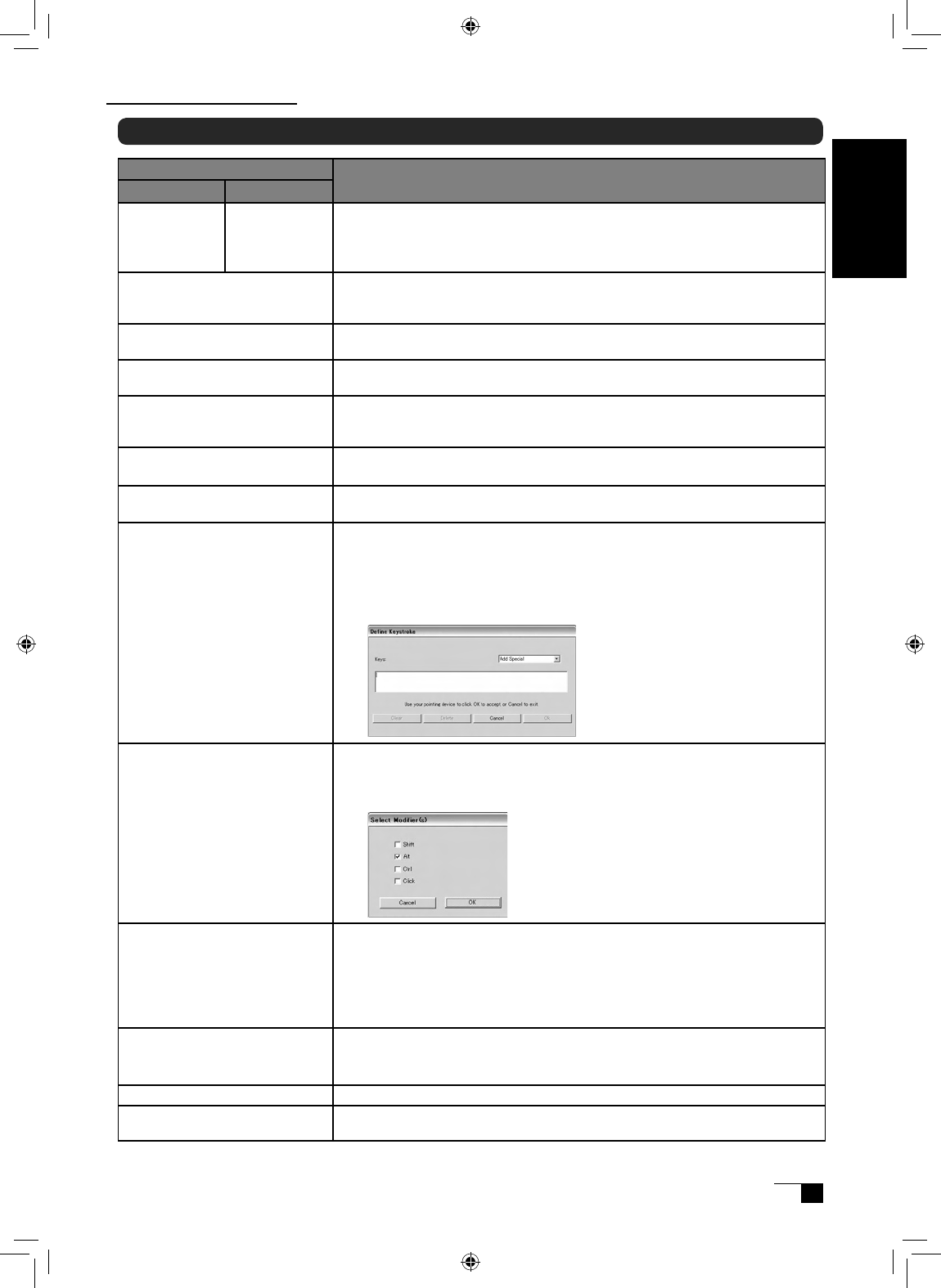
Keystroke Enables you to simulate a series of keystrokes. Selecting this option dis-
plays the define keystroke dialog box, where you can enter a keystroke
or keystroke sequence to play back. Keystroke combinations can include
letters, numbers, function keys (such as F3) and modifier keys (such as
SHIFT, ALT, or CTRL for Windows, or SHIFT, OPTION, COMMAND, and
CONTROL for Macintosh).
MODIFIER Enables you to assign modifier key(s) (such as SHIFT or CTRL). Many ap-
plications use modifier keys to constrain the size or placement of objects.
Selecting this option displays the DEFINE MODIFIER dialog box where
you can assign one or more modifier key functions.
Pan/Scroll Pan/Scroll allows you to move an open file or image within a window. This
function can only be set to the Side Switch.
In an application that does not provide a free-hand tool, scroll speed can
be set to one of 5 speeds. Move the slider to the desired setting.
・Slow: reduces scroll speed
・Fast: increases scroll speed.
Pressure Hold
* Displays only with the use of the Side
Switch or Second Side Switch.
Sets the button so that, when pressed, the pressure is locked at the current
pressure level until the button is released. For example, you can paint with
pressure sensitivity until you reach the bush size that you like.
Mode Toggle Toggles between Pen Mode and Mouse Mode.
Tablet PC Input Panel In Windows Vista and tablet PCs, this function will open the tablet PC input
panel.
Using the Control Panel
User's Guide
UM-0314(A)_EN.indd 21 2007/11/12 16:53:18
Function Names
Description
Windows Macintosh
Journal This function opens Microsoft Journal, an application for Windows Vista
and tablet PC.
Open/Run... Opens an application or file.
This function will open a dialog box. Click Browse to select an application
or file. The selection you make appears in the Application To Run box. Click
"OK" to accept the selection.
Ink Toggle Lets you use your pen to toggle the Ink Anywhere function of Inkwell on
and off. Note that Ink must be turned on for this button function to work.
Application Defined Allows the application to determine the button function. Use this for appli-
cations such as CAD programs that have built-in button support.
Default Settings Click on this button and all settings return to their default settings.
Disabled Disables the button function.
Customizing the Pop-up Menu
Use the POP-UP MENU tab to define the available functions on the Pop-up Menu list.
To display the Pop-up Menu, set a tool button to the POP-UP MENU function. Whenever you press
that button, the Pop-up Menu is displayed. Select from available items in the Pop-up Menu by
clicking on them. To close the Pop-up Menu without making a selection, click outside of the Pop-up
Menu.
NO Setting Item Description
1Button function Select a button function to add to the Pop-up Menu list.
2Remove Removes the selected item from the list.
3Pop-up Items Displays a list of functions that have been added to the
Pop-up Menu. To change the order of an item, drag it
to a new location. Double-click on an item to make edits.
4Pop-up Font and Font Size Sets the FONT and FONT SIZE of the Pop-up Menu.
5Default Returns all tab settings to their default values.
This action will delete all Pop-up Menu items that have
been defined.
1
2
3
4
5
UM-0314(A)_EN.indd 22 2007/11/12 16:53:19
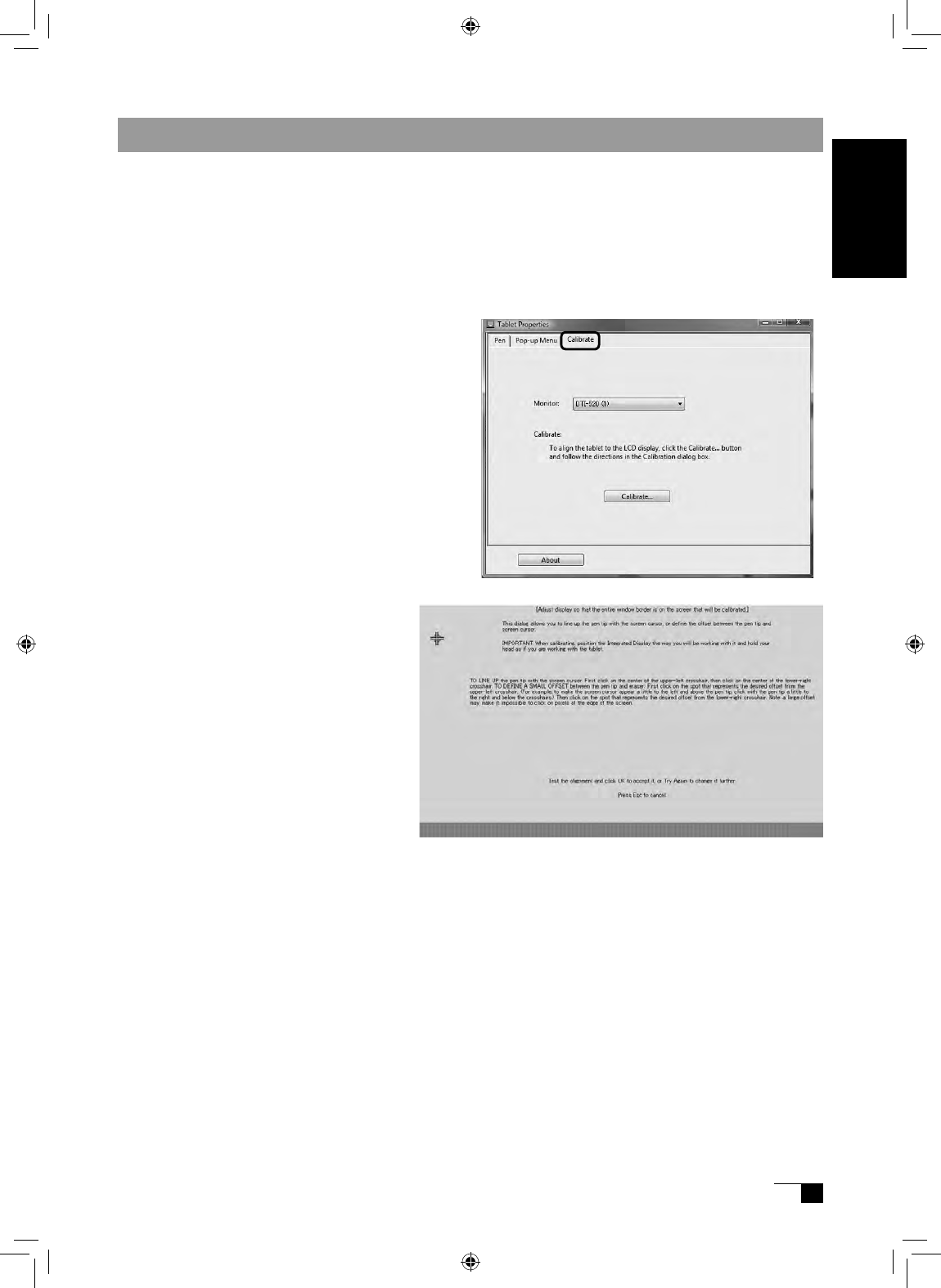
Synchronizing the Positions of the Pen Tip and Pointer
Make the necessary adjustments so that when the pen nib is brought near the LCD screen, the
pointer displays properly in the area where the pen nib is placed (parallactic adjusting).
* When using an analog RGB input type of LCD pen tablet, please refer to “Blurring and Protrusion of the
Picture from the LCD Panel” on P. 14 and make any necessary adjustments to the screen.
* When using multiple tablets, see page 24.
1 Click on Calibrate... and the screen
used for making adjustments will
appear.
2 Click in the middle of the cross mark in
the upper left-hand corner of the screen
while sitting in your normal seating position
with the pen nib and the cross mark will
move to the bottom right-hand side of the
screen.
3 Click again in the middle of the
cro ss mark t hat i s n ow i n t h e
bottom right-hand corner of the
screen while sitting in your normal
seating position and the cross
mark will disappear. The process
of synchronizing positions is now
complete.
Click on the OK button in the lower part
of the screen to close the screen.
User's Guide
UM-0314(A)_EN.indd 23 2007/11/12 16:53:19
Using Multiple Interactive Pen Displays
When multiple interactive pen displays are connected and are to be used, it is necessary to set up the
pen and calibrate for each interactive pen display individually. Please follow the procedures below to
carry this out.
1Bring the pen tip near the display for which the setup is to take place. Verify that the pointer
moves in conjunction with the pen tip.
2Open the control panel. (Please refer to the screenshot accompanying Step 1 of the procedure
described in “Blurring and Protrusion of the Picture from the LCD Panel” on P. 14)
3Open the Calibrate tab and verify that the correct monitor name is displayed in the Monitor field.
●If Another Monitor Name is Displayed in the Monitor Field...
The control panel of a different interactive pen display is being displayed. Press the ESC key on
the keyboard to close the control panel and, beginning with Step 1, repeat the above procedure
to display the correct control panel.
*If the monitor name is changed without displaying the control panel, the tablet will not be set up correctly.
【Important】
When more than one interactive pen tablet is connected, the control panel of the last
tablet to recognize the pen tip is displayed. Even after identifying the pointer, if you
use the pen on another tablet to open its control panel, the pen tip is recognized and
the control panel of this tablet opens. Please refer to the following example.
Example >Setting up Display A when Displays A and B are connected.
1. The pointer is identified by Display A.
2. The control panel of Display A is displayed. →OK
The pen is used on Display B to display the control panel →NOT OK (This carries out the
setup of Display B)
The computer mouse is used on Display B to display the control panel →OK
4Refer to “Blurring and Protrusion of the Picture from the LCD Panel” on P. 14 and carry out calibra-
tions.
To set up the pen, open the PEN tab, refer to “Switch and Button Settings” on P. 21 and carry out the
setup.
5Repeat Steps 1 – 4 to set up another display.
Depending on your PC graphics card or driver, multi-monitor set up may not be
available.
Caution
UM-0314(A)_EN.indd 24 2007/11/12 16:53:19
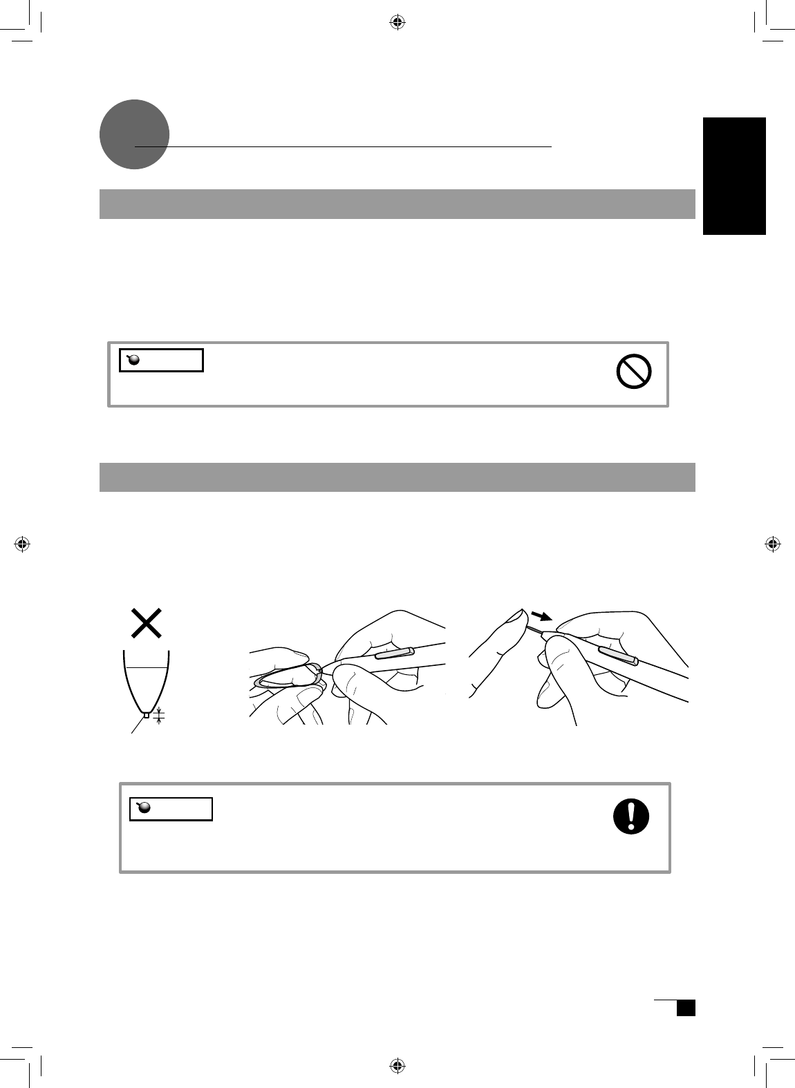
Remove the pen nib Insert a new nib
Please prevent children from placing the grip pen or pen nib
in their mouths. There is the danger that the nib may be pulled
out and swallowed. If the grip pen is placed in the mouth, it
may be damaged.
Supplementary Information
Using a pair of tweezers or a similar
tool, pull the nib out of the pen.
Insert the new nib, firmly pushing it
in until it stops.
Removing Stains
If the product casing or pen becomes soiled, wipe off with a clean, soft cloth.
If this fails to remove the stains, soak a clean, soft cloth with a water-diluted detergent mixture,
wring thoroughly and wipe off.
If the protective covering for the LCD display becomes soiled, wipe with a dry, soft cloth. If the
stain is difficult to remove, try moistening the cloth slightly.
Do not use detergents for cleaning. The use of detergents may
adversely affect the performance of the pen. Also, do not use
organic solvents, as they may cause surface discolouration.
Replacing the Pen Nib
When the pen nib becomes worn down so that it is 1mm or less in length, replace it as shown in the
illustration below. If the pen nib becomes worn down and angular in shape, it can easily damage the
surface of the protective covering of the LCD display.
Pen nib
Less than 1mm
Caution
Caution
User's Guide
UM-0314(A)_EN.indd 25 2007/11/12 16:53:20
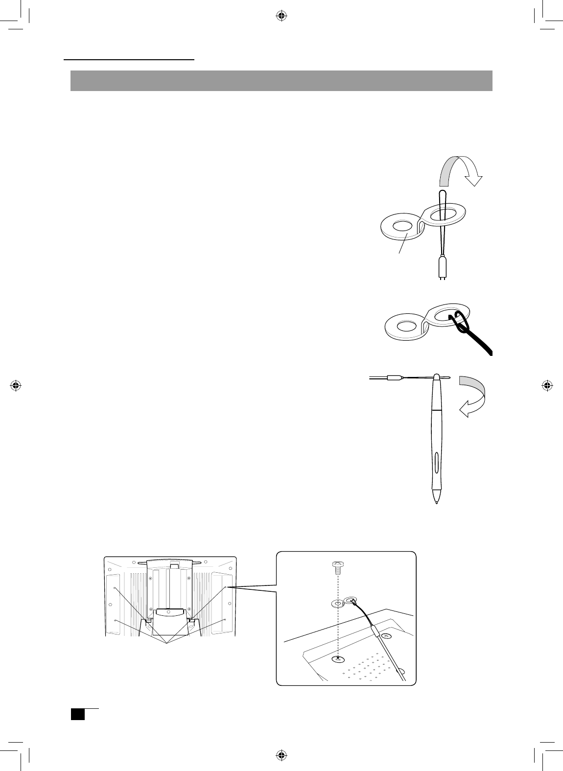
Attaching the Pen Tether
The pen tether may be attached to ensure that the pen is not lost or mislaid.
Procedure:
1Pass the tip of the pen tether through the fitting.
2.Pass the tip through the loop of the opposite end of the pen tether.
3.Pass the opposite tip of the pen tether through the hole at the
top of the pen, and then pass the fitting through the loop.
4.Secure the fitting with the screws provided. The fittings may be installed in any one of the
four holes shown below.
Screw Holes
Installation
Fitting
Supplementary Information
UM-0314(A)_EN.indd 26 2007/11/12 16:53:21
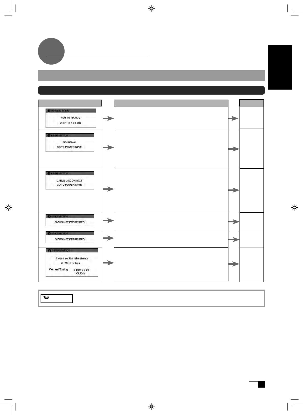
Message
Display Troubleshooting
What to Do
Prior to connecting the product, if you have a monitor
that you have been using, connect it and then adjust
the horizontal frequency to 30–80 kHz and the vertical
frequency to 50 –75 Hz. Connect the product.
- Verify that the video signal cable* is connected.
- Verify that the video signal cable connector pins are not
bent or broken.
• When the computer goes in to power saving mode,
move the mouse or press any keyboard key.
• Verify that the computer graphics board is correctly
installed.
• Verify that the video signal cable is connected.
• Verify that the video signal cable connector pins are not
bent or broken.
• If you are using a cable other than the video signal cable
that was included with the product, this message may
appear prior to the computer going into power-saving
mode. The product is not out of order. Use the cable that
was included to connect the product.
The RGB – RGB cable is not connected.
The composite video cable is not connected.
Set the refresh rate so that it is 70Hz or less.
The refresh rate may be adjusted at the Screen Profile
dialog box for your computer.
Reference
ー
P.10-11
ー
ー
ー
P.10-11
ー
P.9
P.10-11
P.10-11
ー
If One of These Messages Should Appear...
Troubleshooting
* Video signal cable indicates both USB cables (see page 9).
Caution
User's Guide
UM-0314(A)_EN.indd 27 2007/11/12 16:53:21
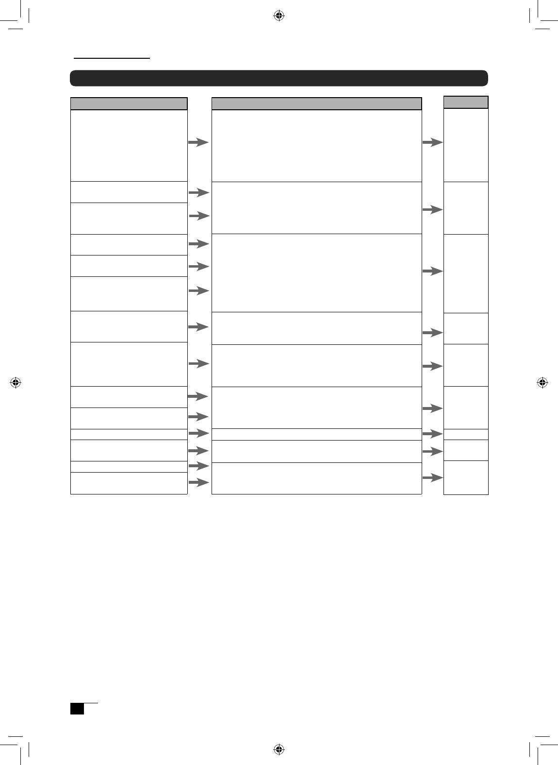
If One of These Conditions Should Appear...
Condition
The power lamp lights up orange or
orange and blue.
The power lamp doesn’t light up
and the screen doesn’t display.
The screen doesn’t display even
when the power switch is turned on.
The picture is distorted
The picture appears wavy
The picture flickers
The picture is not clear
The picture appears doubled or in
triplicate
The picture is out of position
The picture size is incorrect
The picture is dark.
Waves and vertical stripes appear in
the picture.
The picture color is uneven.
The color white does not display as
white.
What to Do
• Verify that the video signal cable is connected.
• Verify that the video signal cable connector pins are not
bent or broken.
• When the computer goes in to power saving mode,
move the mouse or press any keyboard key.
• Verify that the computer graphics board is correctly
installed.
• Verify that the power cable is connected and turn the
power switch on.
•Adjust the pitch and phase.
•Verify that your computer display adapter is compatible
with the product.
•Verify that the graphics mode and frequency for the
input signal are compatible with the product.
•Adjust the computer’s refresh rate (vertical frequency) for
optimal display.
•Adjust the contrast and brightness.
•Adjust the pitch and phase.
•Set your computer’s resolution to SXGA (1280 x 1024).
•Do not add an extension to the video signal cable and
refrain from using the input selector.
•Connect the video signal cable firmly to the connector.
•Adjust the pitch and phase.
•Adjust the horizontal and vertical positioning. Depending
on the input signal and video card, the picture may not
entirely fill the screen.
•Adjust the brightness.
•Adjust the pitch and phase.
•Adjust the color temperature.
Reference
P.10-11
ー
ー
ー
P.10-11
ー
P.15-17
ー
P.31
P.31
P.15-17
P.15-17
ー
ー
ー
P.15-17
P.15-17
P.15-17
P.15-17
P.15-17
Troubleshooting
UM-0314(A)_EN.indd 28 2007/11/12 16:53:21
The Pen and Side Switch do not Operate Correctly (For Both Windows and Macintosh)
Condition
The pen nib produces a click even
when only very lightly coming in
contact with the screen.
The pen does not produce a click
unless excessive pressure is used.
The pen nib produces a click prior to
coming into contact with the screen.
The pen nib and side switch do not
work.
The side switch does not work.
The pen cannot be double-clicked
using the pen nib.
The pressure function cannot be
used.
What to Do
Use the control panel to set the pen nib sensitivity to Firm
setting.
Use the control panel to set the pen nib sensitivity to Soft
setting.
Use the control panel to set the pen nib sensitivity to Firm
setting.
When the status lamp turns blue in response to the pen
nib being moved to close proximity to the screen, either
the pen or the tablet is probably defective.
Please verify that the status lamp turns blue when the
pen nib and side switch are pushed. If the lamp doesn’
t change color, this probably indicates that either the pen
or the tablet is probably defective.
Verify that the side switch setting in the control panel isn’t
set to Not Available. .
If possible, quickly click in the same area.
You can also set the side and second side switches so
that one click is the equivalent of a double-click.
In the control panel, set the double-clicking interval to a
longer setting and set the pen nib sensitivity to a lighter
setting.
Verify that the double-click speed setting is not too fast in
the regular mouse control panel.
Please refer to your software application and the store
where you bought the application to verify whether it
is pressure function-enabled. Some applications have
special settings that must be established before the
pressure function becomes operational.
The tablet driver probably is not installed properly. Try re-
installing it.
Reference
P.20
P.20
P.20
P.6
P.20-22
ー
P.20-22
P.20-22
ー
ー
P.12
Condition
When a replacement computer is
purchased or new software is used,
the tablet cannot be used.
The tablet, which is connected to a
USB hub, doesn’t respond.
What to Do
Installing the newest version of tablet driver may
resolve this problem. The newest tablet driver can be
downloaded from the Wacom homepage.
Some USB hubs cannot recognize tablets. Connect the
tablet directly to the computer’s USB port.
Reference
ー
ー
General Troubleshooting
User's Guide
UM-0314(A)_EN.indd 29 2007/11/12 16:53:22
0
Troubleshooting for Windows
Condition
Even when connected to the USB
port, the pen is inoperable.
When Windows is in DOS full screen
mode, moving the pointer with the
pen becomes impossible.
If the mouse is set for left-handed
use in the regular mouse control
panel, the ability to click with the
pen nib is lost.
What to Do
•Check the connection of the USB connector. If using
a USB hub connection, try connecting directly to the
computer’s USB port.
•When the product model type appears in the Unknown
Device list, select it and click the Delete button, canceling
all settings for it. Next, click the Renew button and,
following the directions in the New Hardware dialog box,
re-install the tablet driver.
•If use of the USB port is advantageous, open the Control
Panel folder and then the System folder. Then open, in
order, the Hardware and Device Manager folders. Next,
check and make sure that USB (Universal Serial Bus)
Controller appears in the list that is displayed. If it isn’
t present, it will be necessary to adjust your computer.
Please consult your computer maker regarding this.
When using a DOS mouse, the pen is inoperable. You
must use another mouse.
Restart Windows.
Reference
P.10-11
ー
ー
ー
ー
Troubleshooting for Macintosh
Condition
Even when connected to the USB
port, the pen is inoperable.
The product always reverts to
mouse mode and the pressure
function cannot be used.
What to Do
-Check the connection of the USB connector. Connect
directly to the computer’s USB port.
-If equipped with a USB card, the system software has
probably not been installed properly.
-If you have any other high-speed, high-power USB
peripherals, connect these and check and see whether
they operate properly or not. If these other units operate
properly, this would seem to indicate that the tablet is
defective.
The tablet driver may not be properly installed. Try
reinstalling it.
Reference
P.10-11
ー
ー
P.12
Troubleshooting
UM-0314(A)_EN.indd 30 2007/11/12 16:53:22
General Specifications
Physical dimensions(W D H): 344 × 300 × 49 mm (excluding stand)
Weight: 4.6kg (including stand)
Main unit input voltage: DC12V
Power consumption: 23 W or less (DC12 V)
Usage temperature and
humidity ranges: 5–35 degrees C, 20–80%RH (conditions where condensation does not form)
Storage temperature and
humidity ranges: -10–60 degrees C, 20–90%RH (conditions where condensation does not form) (at 60
degrees C maximum storage humidity is 38%; at 90% humidity, maximum storage
temperature is 42 degrees)
LCD Display Specifications
Display: a-Si TFT Active Matrix LCD
Screen size: 15 inches
Resolution (75Hz Max.): 1024 × 768 dot (XGA), 800 × 600 dot (SVGA), 640 × 480 dot (VGA)
Pixel pitch: 0.297(W) × 0.297 (H) mm
Display dimensions: 304.1 × 228.1mm
Color depth: 253 level; 16,190,000 colors
Signal inputs: Analog RGB input 0.7 Vp-p, 75Ω, straight polarity
Synchronous inputs: TTL level, 2.2 kΩ, polarity freedom (horizontal / vertical separation or
composite synchronous input)
Digital inputs: DVI 1.0
Synchronous frequency: horizontal: 30 – 56.5 kHz; vertical 45 – 75 Hz .(When resolution
is 1024 × 768 dot (XGA), vertical frequency is in the 45-70Hz range.)
Scanning method: all non-interlace
Plug and Play: DDC2B
* On rare occasions, light and dark dots may appear on a small part of the display screen. This condition does not
indicate product failure.
* Afterimages may remain on the screen after still images have been displayed for a long period of time, but these will
disappear after a short period of time.
Tablet Specifications
Reading method: Electromagnetic induction method
Maximum reading range: 304.1 × 228.1mm
Reading resolution: Maximum 20 lpmm (0.05 mm)
Reading accuracy: +/- 0.5 mm; four corners(25mm wide, 80mm long from each corner of four "L" shaped
area) to be +/- 1.5 mm.
Maximum reading height: 5mm
Data transfer rate: Maximum 100 points per second
Pressure level: 512 levels
Interface: USB, RS-232C
Specification
Grip Pen Specifications (IP-110)
Side switch type Double
Pressure functions: Pen nib switch
Pen nib switch type
/retraction motion:
Non-retractable/0.2 mm or less
Load when pen nib is switched on:
30 g or less
Physical dimensions and weight:
12.5 × 147.5 mm, 10 g
User's Guide
UM-0314(A)_EN.indd 31 2007/11/12 16:53:22

Warranty
(WORLDWIDE, EXCEPT FOR EUROPE, AFRICA AND MIDDLE EAST)
Limited warranty
Wacom warrants the product, to the original consumer purchaser, except for the Software
and consumable items such as the pen nibs, to be free from defects in materials and
workmanship under normal use and service for a period of two (2) years, from the date of
original retail purchase, as evidenced by a copy of the receipt and registration with Wacom
within 30 days of purchase.
The Software is licensed “as is.” Wacom makes no warranty with respect to its quality or
performance.Wacom cannot guarantee you uninterrupted service or the correction of any
errors.
Upon discovery of a defect in the product, except in the Software, within the Warranty Period,
you should contact Wacom Technical Support via telephone, email, or fax to obtain an RMA
(Return Merchandise Authorization) number and instructions for shipping the product to a
service location designated by Wacom. You should send the product, shipping charges
prepaid, to the designated service location, accompanied by the return authorization number,
your name, address and telephone number, proof of purchase date, and a description of
the defect. Wacom will pay for return shipping by United Parcel Service or by an equivalent
service as chosen by Wacom.
Wacom’s sole obligation and entire liability under this warranty shall be, at Wacom’s option,
either the repair or replacement of the defective product or parts thereof of which Wacom is
notified during the Warranty Period;provided, however, that you are responsible for (i) the cost
of transportation of the product to the designated service location and (ii) any loss or damage
to the product resulting from such transportation.
Wacom shall have no responsibility to repair or replace the product if the failure of the product
has resulted from accident, abuse, misuse, negligence, or unauthorized modification or repair, or
if it has been handled or stored other than in accordance with Wacom’s storage instructions.
Any descriptions, drawings, specifications, samples, models, bulletins, or similar material,
used in connection with the sale of the product, shall not be construed as an express
warranty that the product will conform or comply with your requirements.
EXCEPT FOR THE LIMITED WARRANTY DESCRIBED ABOVE, THERE ARE NO OTHER WARRANTIES
MADE BY WACOM ON THIS PRODUCT. NO ORAL OR WRITTEN INFORMATION OR ADVICE
GIVEN BY WACOM, ITS DEALERS, DISTRIBUTORS, AGENTS, OR EMPLOYEES SHALL CREATE A
WARRANTY OR IN ANY WAY INCREASE THE SCOPE OF THIS WARRANTY, AND YOU MAY NOT
RELY ON ANY SUCH INFORMATION OR ADVICE. THIS WARRANTY GIVES YOU SPECIFIC LEGAL
RIGHTS, AND YOU MAY ALSO HAVE OTHER RIGHTS WHICH VARY FROM STATE TO STATE.
WACOM LIMITS THE DURATION OF ANY LEGALLY IMPLIED WARRANTIES INCLUDING IMPLIED
WARRANTIES OF MERCHANTABILITY OR FITNESS FOR A PARTICULAR PURPOSE, TO THE
DURATION OF WACOM’S EXPRESS WARRANTY. SOME STATES DO NOT ALLOW LIMITATIONS
ON HOW LONG AN IMPLIED WARRANTY LASTS, SO THE ABOVE LIMITATION MAY NOT APPLY
TO YOU.
NEITHER WACOM NOR ANYONE ELSE WHO HAS BEEN INVOLVED IN THE CREATION,
PRODUCTION, OR DELIVERY OF THIS PRODUCT SHALL BE LIABLE FOR ANY DIRECT,
CONSEQUENTIAL, OR INCIDENTAL DAMAGES (INCLUDING DAMAGES FOR LOSS OF BUSINESS
PROFITS, BUSINESS INTERRUPTION, LOSS OF BUSINESS INFORMATION AND THE LIKE)
ARISING OUT OF THE USE OF OR INABILITY TO USE SUCH PRODUCT, EVEN IF WACOM HAS
BEEN ADVISED OF THE POSSIBILITY OF SUCH DAMAGES. SOME STATES DO NOT ALLOW THE
EXCLUSION OR LIMITATION OF INCIDENTAL OR CONSEQUENTIAL DAMAGES, SO THE ABOVE
LIMITATION OR EXCLUSION MAY NOT APPLY TO YOU.
UM-0314(A)_EN.indd 32 2007/11/12 16:53:22

In the event that any of the above limitations are held unenforceable, Wacom’s liability for any
damages to you or any party shall not exceed the purchase price you paid, regardless of the
form of any claim.
This Limited Warranty is governed by the laws of the United States of America and the state
of Washington. This Limited Warranty is valid for and only applies to products purchased and
used inside the United States (and its territories or possessions) and Canada.
Warranty service outside of the U.S.A. and Canada
For products purchased or used outside of the United States and Canada, the warranty
period is one (1) year from the date of original retail purchase. Upon discovery of a defect
in the product, except in the Software, within the Warranty Period you should contact your
local dealer or distributor. If an authorized Wacom repair center is not available in your local
country you will be responsible for all transportation costs including duties and taxes to and
from the Wacom repair center. In all other respects the terms of the warranty as set forth
above apply to such sales.
User's Guide
UM-0314(A)_EN.indd 33 2007/11/12 16:53:22

Obtaining Technical Support
If you experience a problem with this product that cannot be solved by referring to this
guide or the manual included with your driver CD, please refer to our online FAQ or
contact our support staff.
Online FAQ: http://www.wacom-asia.com/faq/faq_index.html
Email: http://www.wacom-asia.com/contact/contact_index.html
Phone support is available from 9:00 am - 6:00 pm on weekdays:
Tel: +81-3-5309-1588, Fax: +81-3-5309-1514
(International calling fees differ by region.)
-------------------------------------------------
Support for Hong Kong residents is available from Wacom Hong Kong Ltd.
URL: www.wacom.com.hk
Tel: (852) 2836-8186, Fax: (852) 3519-4833
Email: sales:wacom.com.hk
-------------------------------------------------
Regarding Limited Warranty in the Asia Pacific region (excluding China and Hong Kong)
Wacom Co., Ltd. warrants the product, to the original consumer purchaser, including
the main unit and accessories such as the AC adapter and cables, to be free from
defects in materials and workmanship under normal use and service for a period of one
(1) year, from the date of original retail purchase, as evidenced by a copy of the receipt
(proof of purchase) or if issued, the warranty card from your local reseller or distributor.
Wacom's Limited Warranty Policy for Asia Pacific can be found on the Asia Pacific
website at: www.wacom-asia.com/technical/warranty/img/Limited_Warranty_AP.pdf
Premium Extended Warranty Service is available in Asia Pacific
http://www.wacom-asia.com/technical/warranty/premiumwarranty.html
UM-0314(A)_EN.indd 34 2007/11/12 16:53:23

Wacom Co., Ltd.
Printed in Taiwan
UM-0314(A)
Interactive Pen Display DTI-520 User's Guide
©2007 Wacom Co., Ltd. All rights reserved.
DTI-520(A)_1-4.indd 2 2007/11/12 13:49:11
