Wagner 833 User Manual AIRLESS PAINT SPRAYER Manuals And Guides 1312241L
User Manual: Wagner 833 833 WAGNER AIRLESS PAINT SPRAYER - Manuals and Guides View the owners manual for your WAGNER AIRLESS PAINT SPRAYER #833. Home:Tool Parts:Wagner Parts:Wagner AIRLESS PAINT SPRAYER Manual
Open the PDF directly: View PDF ![]() .
.
Page Count: 20
i
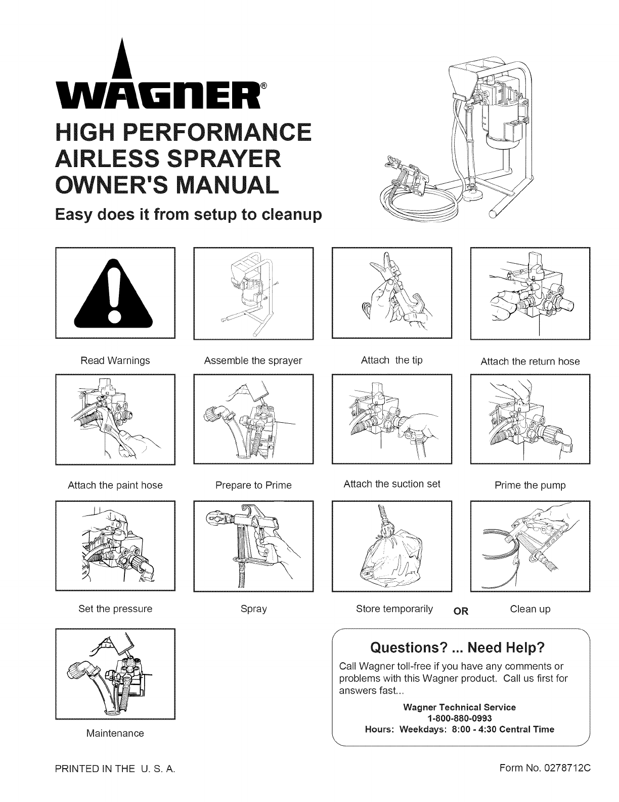
WJ GnE ®
IG PE
AI LE
ER'S
ANCE
PRAYER
A UAL
Easy does it from setup to cleanup
Read Warnings
Attach the paint hose
!
Assemble the sprayer
Prepare to Prime
Set the pressure Spray
Maintenance
Attach the tip Attach the return hose
Attach the suction set Prime the pump
Store temporarily OR Clean up
JQuestions? ... Need Help?
Call Wagner toll-free if you have any comments or
problems with this Wagner product, Call us first for
answers fast,,,
Wagner Technical Service
1-800-880-0993
Hours: Weekdays: 8:00 - 4:30 Central Time
PRINTED IN THE U. S.A. Form No. 0278712C
CONTENTS
COMPONENTS .............................................................. 2
GENERAL DESCRIPTION ............................................. 2
Specifications ........................................................... 2
SAFETY PRECAUTIONS ........................................... 3-4
GROUNDING INSTRUCTIONS ...................................... 5
SETUP ........................................................................ 5-7
Assembling the sprayer ........................................ 5-6
Attaching the tip to the gun ....................................... 6
Attaching the return hose ......................................... 6
Attaching the paint hose ........................................... 7
PRESSURE RELIEF PROCEDURE ............................... 7
PRIMING ..................................................................... 8-9
Preparing to prime .................................................... 8
Attaching the suction set .......................................... 8
Priming the pump ..................................................... 8
SPRAYING ...................................................................... 9
Spraying technique ................................................... 9
Practice ................................................................... 10
If the spray tip becomes clogged ............................ 10
Cleaning the spray gun filter ............................. 10-11
Cleaning the filter during the painting process ....... 11
Cleaning the suction set screen ............................. 11
CLEANUP ............................................................... 12-14
Overnight storage ................................................... 13
Long-term storage ............................................ 12-14
MAINTENANCE ...................................................... 14-15
Removing and cleaning the inlet valves ........... 14-15
Removing and cleaning the outlet valve ................. 15
Tightening the PRIME/SPRAY knob ...................... 15
TROUBLESHOOTING .................................................. 17
PARTS LISTS ......................................................... 18-19
Final Assembly ....................................................... 18
Paint Pump Assembly ............................................ 18
Suction Set Assembly ............................................. 19
G-06 Spray Gun ..................................................... 19
WARRANTY .................................................... back cover
COMPONENTS
The shipping carton contains the following components:
• The stand (unassembled), motor and pump.
o Pail bracket.
Suction set and return tube.
Spray gun and filter.
Spray tip and gasket.
25', 1/4" diameter pressure hose.
The following are located in the literature set with the
registration card:
• Spare Outlet Spring, PIN 0047485
• Spare Tip Seal, PIN 0156713
• Return tube fitting, PIN 0088715
• Operator's manual
© 1995 Wagner Spray Tech
GENERAL DESCRIPTION
This High Performance Airless Sprayer is a precision
power tool used for spraying many types of materials.
Read and follow this instruction manual carefully for
proper operating instructions, maintenance and safety
information.
Specifications
Weight ........................ 27 Ibs. (12 kg )
Capacity ..................... Up to .35 gallon (1-1/4 liters) per
minute.
Power source ............. 1/2 HP electric motor, enclosed,
fan cooled.
Power requirement ..... 15 amp minimum circuit on 115
VAC, 60 Hz current.
Generator ................... 15 amp A/C.
Spraying pressure ......
Safety features ...........
Portability ...................
Capability ...................
Up to 2,600 psi.
Spray gun safety lock and pres-
sure diffuser; built-in tip safety
guard; priming knob for safe
pressure release.
Compact design, light weight for
easy movement.
Sprays a variety of paints, oil
base, latex, primers, stains,
preservatives and other nonabra-
sive materials, including pesti-
cides and liquid fertilizers.
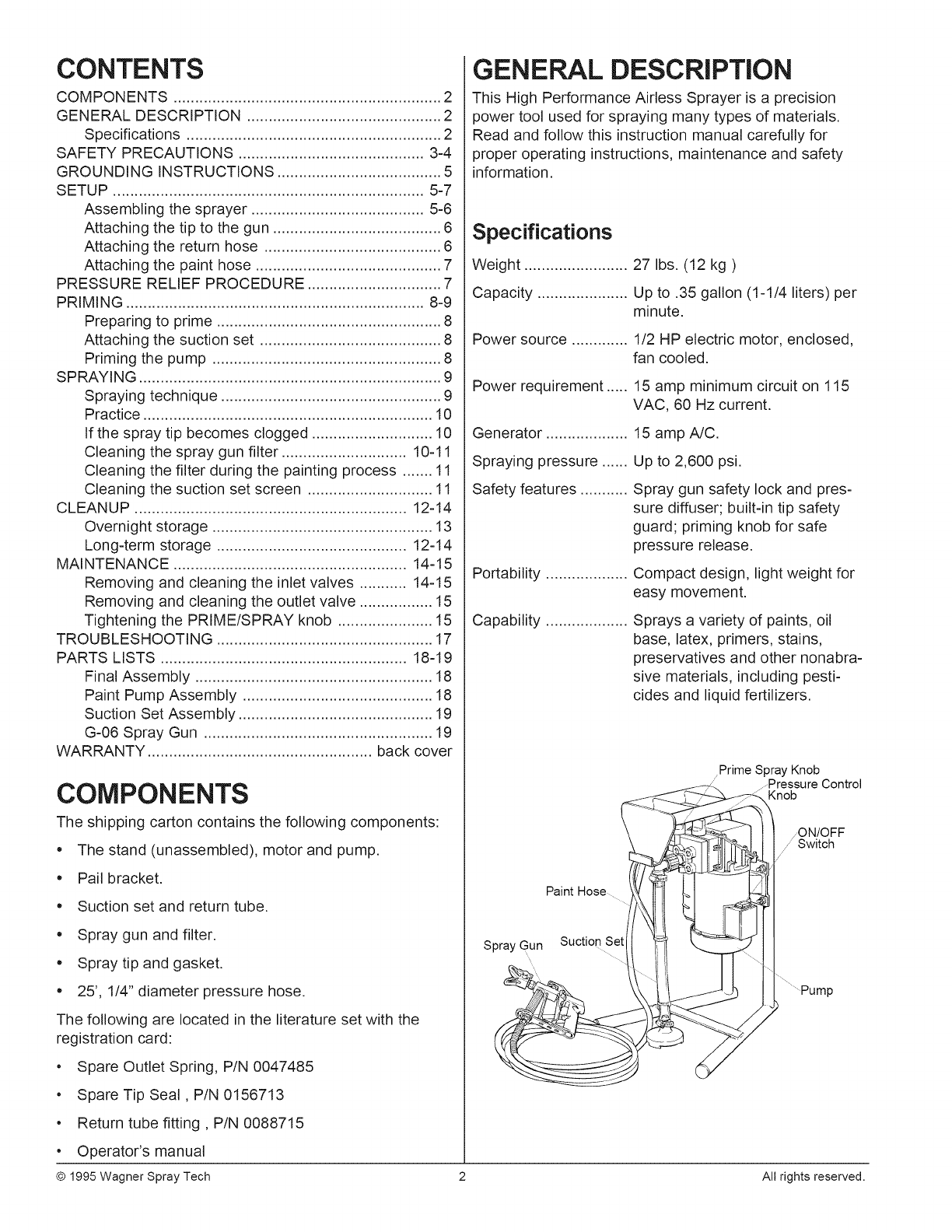
Paint Hose
Spray Gun Suction SI
Prime Spray Knob
....Pressure Control
Knob
ON/OFF
/Switch
.............Pump
2 All rights reserved.
SAFETY PRECAUTIONS
This manual contains information which must be read
and understood before using the equipment. When you
come to an area which has one of the following symbols,
pay particular attention and make certain to heed the
safeguard.
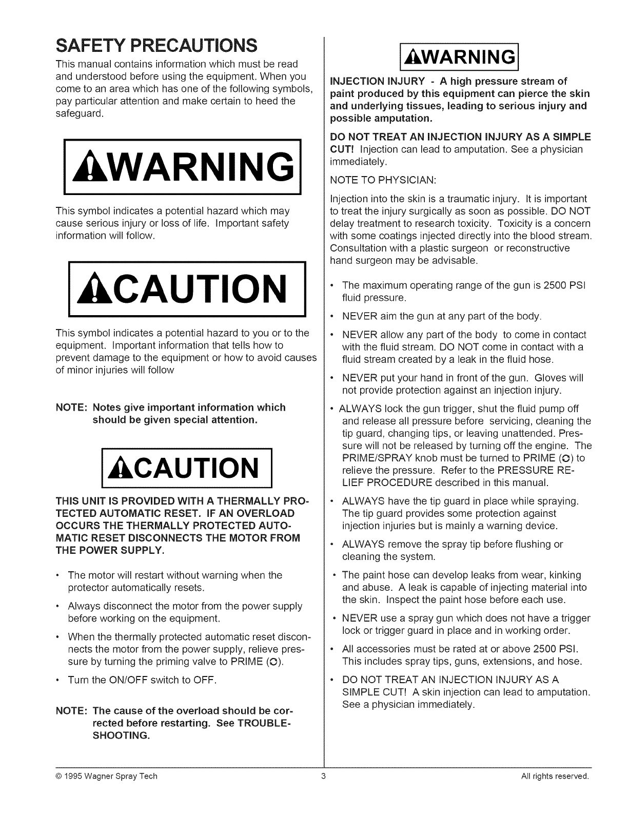
kWARNING
This symbol indicates a potential hazard which may
cause serious injury or loss of life. Important safety
information will follow.
kCAUTION
This symbol indicates a potential hazard to you or to the
equipment. Important information that tells how to
prevent damage to the equipment or how to avoid causes
of minor injuries will follow
NOTE: Notes give important information which
should be given special attention.
I kCAUTION I
THIS UNIT IS PROVIDED WITH A THERMALLY PRO-
TECTED AUTOMATIC RESET. IF AN OVERLOAD
OCCURS THE THERMALLY PROTECTED AUTO=
MATIC RESET DISCONNECTS THE MOTOR FROM
THE POWER SUPPLY.
The motor will restart without warning when the
protector automatically resets.
Always disconnect the motor from the power supply
before working on the equipment.
When the thermally protected automatic reset discon-
nects the motor from the power supply, relieve pres-
sure by turning the priming valve to PRIME (O).
Turn the ON/OFF switch to OFF.
NOTE: The cause of the overload should be cor-
rected before restarting. See TROUBLE-
SHOOTING.
I ILWARNINGI
INJECTION INJURY - A high pressure stream of
paint produced by this equipment can pierce the skin
and underlying tissues, leading to serious injury and
possible amputation.
DO NOT TREAT AN INJECTION INJURY AS ASIMPLE
CUT7 Injection can lead to amputation. See a physician
immediately.
NOTE TO PHYSICIAN:
Injection into the skin is a traumatic injury. It is important
to treat the injury surgically as soon as possible. DO NOT
delay treatment to research toxicity. Toxicity is a concern
with some coatings injected directly into the blood stream.
Consultation with a plastic surgeon or reconstructive
hand surgeon may be advisable.
• The maximum operating range of the gun is 2500 PSI
fluid pressure.
• NEVER aim the gun at any part of the body.
• NEVER allow any part of the body to come in contact
with the fluid stream. DO NOT come in contact with a
fluid stream created by a leak in the fluid hose.
• NEVER put your hand in front of the gun. Gloves will
not provide protection against an injection injury.
• ALWAYS lock the gun trigger, shut the fluid pump off
and release all pressure before servicing, cleaning the
tip guard, changing tips, or leaving unattended. Pres-
sure will not be released by turning off the engine. The
PRIME/SPRAY knob must be turned to PRIME (O) to
relieve the pressure. Refer to the PRESSURE RE-
LIEF PROCEDURE described in this manual.
ALWAYS have the tip guard in place while spraying.
The tip guard provides some protection against
injection injuries but is mainly a warning device.
ALWAYS remove the spray tip before flushing or
cleaning the system.
The paint hose can develop leaks from wear, kinking
and abuse. A leak is capable of injecting material into
the skin. Inspect the paint hose before each use.
NEVER use a spray gun which does not have a trigger
lock or trigger guard in place and in working order.
All accessories must be rated at or above 2500 PSI.
This includes spray tips, guns, extensions, and hose.
DO NOT TREAT AN INJECTION INJURY AS A
SIMPLE CUT! A skin injection can lead to amputation.
See a physician immediately.
© 1995 Wagner Spray Tech 3 All rights reserved.
I kWARNINGI
EXPLOSION OR FIRE - Solvent and paint fumes can
explode or ignite, causing property damage and/or
severe injury.
• Exhaust and fresh air introduction must be provided to
keep the air within the spray area free from accumula-
tion of flammable vapors.
Avoid all ignition sources such as static electricity
sparks, open flames, pilot lights, hot objects, ciga-
rettes, and sparks from connecting and disconnecting
power cords or working light switches.
• Fire extinguishing equipment must be present and in
good working order.
• Keep the pump away from the spray area to avoid
solvent and paint fumes.
High velocity flow of material through equipment may
develop static electricity. The equipment being used,
as well as objects in and around the spray area must
be properly grounded to prevent static discharge and
sparks.
• Use only conductive or grounded high pressure fluid
hoses for airless applications. Be sure that the gun is
grounded properly through hose connections.
Use extreme caution when spraying paints and other
flammable fluids which have a flashpoint below 70° F
(21 ° C). A fluid's flashpoint is the temperature at
which vapors from the fluid could ignite if exposed to a
flame or spark.
• Follow the material and solvent manufacturer's safety
precautions and warnings.
• When flushing equipment use the lowest possible
pressure.
I kWARNINGI
EXPLOSION HAZARD DUE TO INCOMPATIBLE
MATERIALS - May cause property damage or severe
injury.
o
o
o
Do not use bleach.
Do not use halogenated hydrocarbon solvents.
Halogenated hydrocarbon solvents such as methylene
chloride and 1,1,1 - trichloroethane are not compatible
with aluminum and may cause an explosion. If you are
unsure of a material's compatibility with aluminum,
contact your coating's supplier.
I kWARNINGI
HAZARDOUS VAPORS - Paints, solvents, insecti-
cides, and other materials may be harmful if inhaled,
causing severe nausea, fainting, or poisoning.
Use a respirator or mask whenever there is a chance
that vapors may be inhaled. Read all instructions with
the mask to ensure that it will provide the necessary
protection against the inhalation of harmful vapors.
I kWARNINGI
GENERAL -May cause property damage or severe
injury.
Read all instructions and safety precautions before
operating any equipment.
Comply with all appropriate local, state, and national
codes governing ventilation, fire prevention, and
operation.
The United States Government Safety Standards have
been adopted under the Occupational Safety and
Health Act (OSHA). These standards, particularly part
1910 of the General Standards and part 1926 of the
Construction Standards should be consulted.
This high pressure airless pump is designed to be
used with manufacturer authorized parts only. When
using this pump with parts that do not comply with the
minimum specifications and safety devices of the
pump manufacturer, the user assumes all risks and
liabilities.
Before each use, check all hoses for cuts, leaks,
abrasion or bulging of cover, as well as damage or
movement of couplings. If any of these conditions
exist, replace the hose immediately. Never repair a
paint hose. Replace it with another grounded hose.
All hoses, swivels, guns, and accessories used with
this unit must be pressure rated at or above 2500 PSI.
Do not spray on windy days.
I kCAUTION I
Use only a 3-wire extension cord that has a 3-blade
grounding plug and a 3-slot receptacle that will accept
the plug on the product. Make sure your extension cord
is in good condition. When using an extension cord, be
sure to use one heavy enough to carry the current your
product will draw. An undersized cord will cause a drop
in line voltage resulting in loss of power and overheating.
A 14 or 12 gauge cord is recommended.
© 1995 Wagner Spray Tech 4 All rights reserved.
NOTE: Do not use more than 100 feet of extension
cord. If you need to paint further than 100
feet from your power source, use more paint
hose, not more extension cord. Shorter
extension cords will ensure maximum electri-
cal power for proper operation.
GROUNDING iNSTRUCTiONS
This product must be grounded. In the event of an
electrical short circuit, grounding reduces the risk of
electric shock by providing an escape wire for the electric
current. This product is equipped with a cord having a
grounding wire with an appropriate grounding plug. The
plug must be plugged into an outlet that is properly
installed and grounded in accordance with all local codes
and ordinances.
I kWARNINGI
Improper installation of the grounding plug can result
in a risk of electric shock.
If repair or replacement of the cord or plug is necessary,
do not connect the green grounding wire to either flat
blade terminal. The wire with insulation having a green
outer surface with or without yellow stripes is the ground-
ing wire and must be connected to the grounding pin.
Check with a qualified electrician or serviceman if the
grounding instructions are not completely understood, or
if you are in doubt as to whether the product is properly
grounded. Do not modify the plug provided. If the plug
will not fit the outlet, have the proper outlet installed by a
qualified electrician.
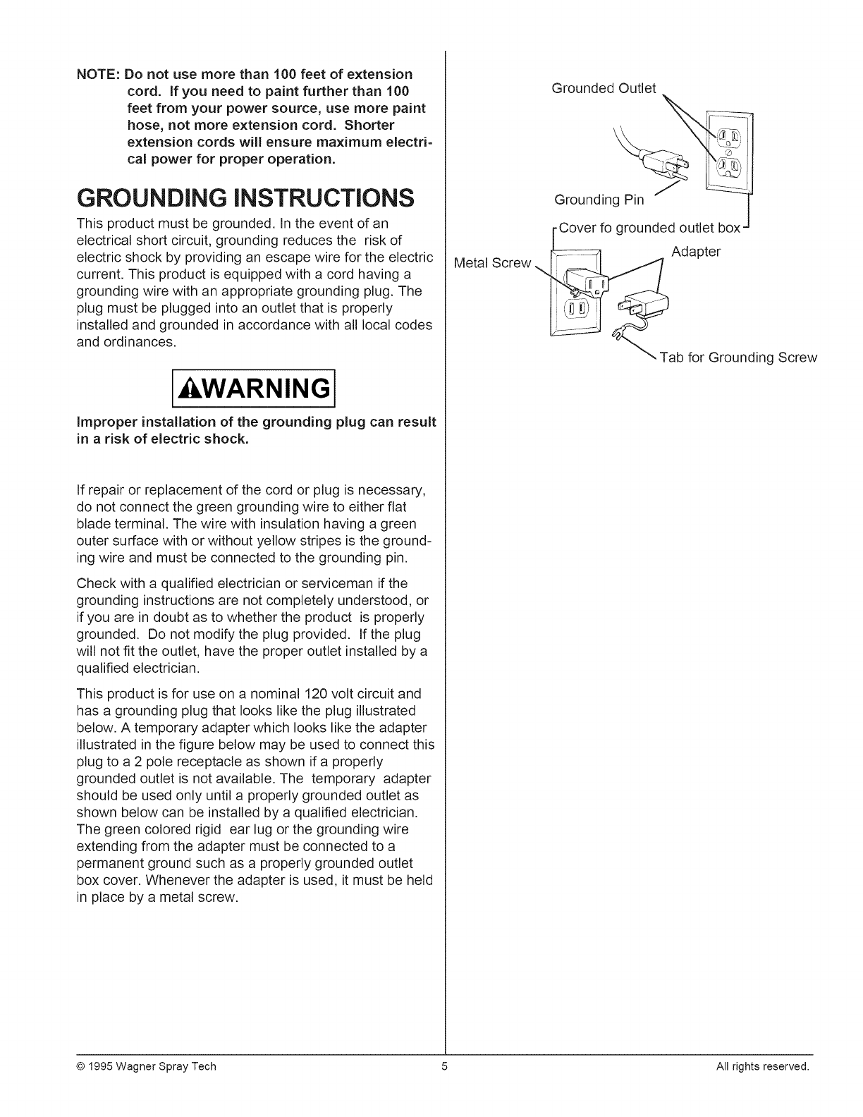
This product is for use on a nominal 120 volt circuit and
has a grounding plug that looks like the plug illustrated
below. A temporary adapter which looks like the adapter
illustrated in the figure below may be used to connect this
plug to a 2 pole receptacle as shown if a properly
grounded outlet is not available. The temporary adapter
should be used only until a properly grounded outlet as
shown below can be installed by a qualified electrician.
The green colored rigid ear lug or the grounding wire
extending from the adapter must be connected to a
permanent ground such as a properly grounded outlet
box cover. Whenever the adapter is used, it must be held
in place by a metal screw.
Metal Screw
Grounded Outlet
Grounding Pin 'j
•Cover fo grounded outlet box
Adapter
_- \Tab for
Grounding Screw
© 1995 Wagner Spray Tech 5 All rights reserved.
SETUP
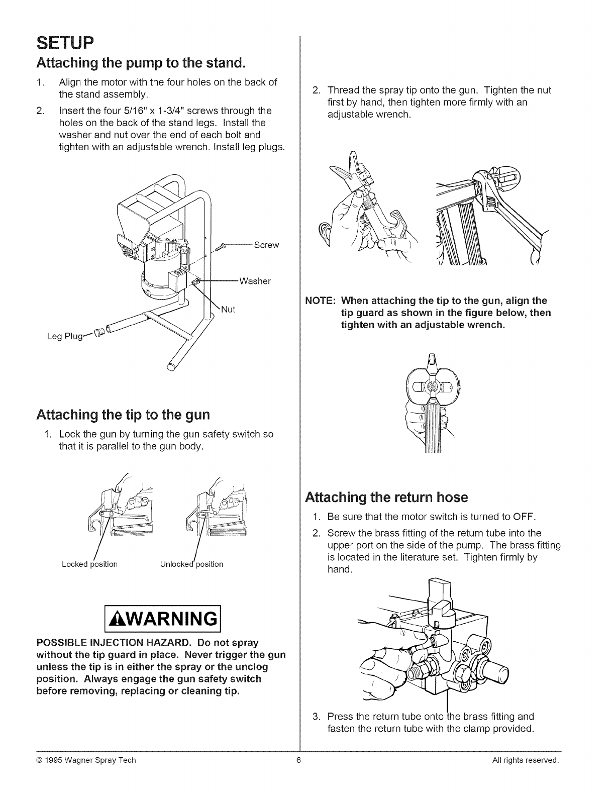
Attaching the pump to the stand.
.
.
Align the motor with the four holes on the back of
the stand assembly.
Insert the four 5/16" x 1-3/4" screws through the
holes on the back of the stand legs. Install the
washer and nut over the end of each bolt and
tighten with an adjustable wrench, Install leg plugs,
Leg PlugI(:_
Attaching the tip to the gun
1. Lock the gun by turning the gun safety switch so
that it is parallel to the gun body,
Locked position Unlocked toosition
I WARNINGI
POSSIBLE INJECTION HAZARD. Do not spray
without the tip guard in place. Never trigger the gun
unless the tip is in either the spray or the unclog
position. Always engage the gun safety switch
before removing, replacing or cleaning tip.
2. Thread the spray tip onto the gun. Tighten the nut
first by hand, then tighten more firmly with an
adjustable wrench.
NOTE: When attaching the tip to the gun, align the
tip guard as shown in the figure below, then
tighten with an adjustable wrench.
Attaching the return hose
1. Be sure that the motor switch is turned to OFF.
2. Screw the brass fitting of the return tube into the
upper port on the side of the pump. The brass fitting
is located in the literature set. Tighten firmly by
hand.
/ ' j
.'-t._ j
3. Press the return tube onto Lhebrass fitting and
fasten the return tube with the clamp provided.
© 1995 Wagner Spray Tech 6 All rights reserved.
s \
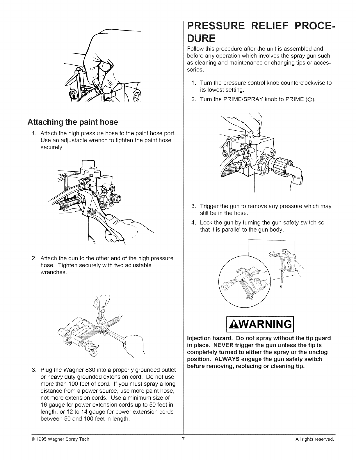
Attaching the paint hose
1. Attach the high pressure hose to the paint hose port.
Use an adjustable wrench to tighten the paint hose
securely.
2. Attach the gun to the other end of the high pressure
hose. Tighten securely with two adjustable
wrenches.
.Plug the Wagner 830 into a properly grounded outlet
or heavy duty grounded extension cord. Do not use
more than 100 feet of cord. If you must spray a long
distance from a power source, use more paint hose,
not more extension cords. Use a minimum size of
16 gauge for power extension cords up to 50 feet in
length, or 12 to 14 gauge for power extension cords
between 50 and 100 feet in length.
PRESSURE RELIEF PROCE-
DURE
Follow this procedure after the unit is assembled and
before any operation which involves the spray gun such
as cleaning and maintenance or changing tips or acces-
sories.
1. Turn the pressure control knob counterclockwise to
its lowest setting.
2. Turn the PRIME/SPRAY knob to PRIME (O).
j
.
.
Trigger the gun to remove any pressure which may
still be in the hose.
Lock the gun by turning the gun safety switch so
that it is parallel to the gun body.
I WARNINGi
Injection hazard. Do not spray without the tip guard
in place. NEVER trigger the gun unless the tip is
completely turned to either the spray or the unclog
position. ALWAYS engage the gun safety switch
before removing, replacing or cleaning tip.
© 1995 Wagner Spray Tech 7 AN rights reserved.
PRiMiNG
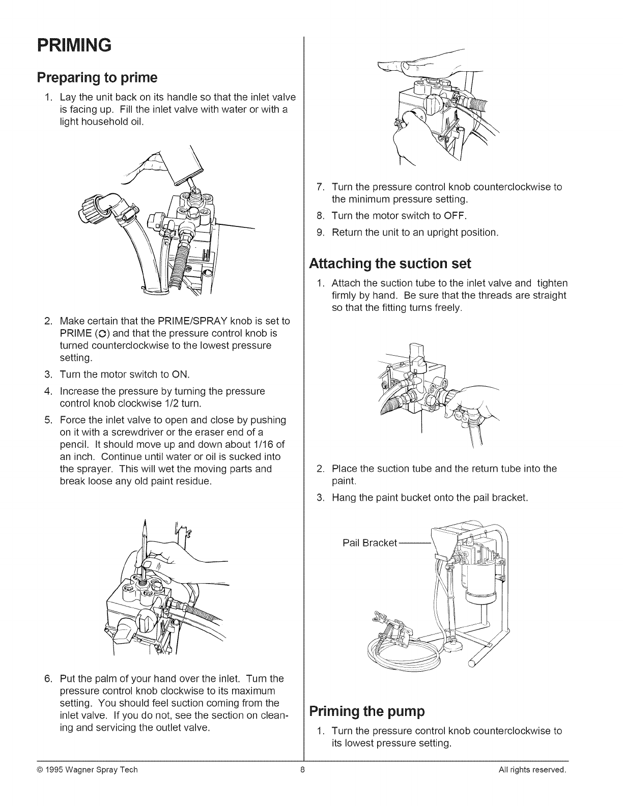
Preparing to prime
1. Lay the unit back on its handle so that the inlet valve
is facing up. Fill the inlet valve with water or with a
light household oil.
.
.
4.
.
Make certain that the PRIME/SPRAY knob is set to
PRIME (O) and that the pressure control knob is
turned counterclockwise to the lowest pressure
setting.
Turn the motor switch to ON.
Increase the pressure by turning the pressure
control knob clockwise 1/2 turn.
Force the inlet valve to open and close by pushing
on it with a screwdriver or the eraser end of a
pencil. It should move up and down about 1/16 of
an inch. Continue until water or oil is sucked into
the sprayer. This will wet the moving parts and
break loose any old paint residue.
.Put the palm of your hand over the inlet. Turn the
pressure control knob clockwise to its maximum
setting. You should feel suction coming from the
inlet valve. If you do not, see the section on clean-
ing and servicing the outlet valve.
.
.
9.
Turn the pressure control knob counterclockwise to
the minimum pressure setting.
Turn the motor switch to OFF.
Return the unit to an upright position.
Attaching the suction set
1. Attach the suction tube to the inlet valve and tighten
firmly by hand. Be sure that the threads are straight
so that the fitting turns freely.
.
.
Place the suction tube and the return tube into the
paint.
Hang the paint bucket onto the pail bracket.
Pail Bracket--
Priming the pump
1. Turn the pressure control knob counterclockwise to
its lowest pressure setting.
© 1995 Wagner Spray Tech 8 All rights reserved.
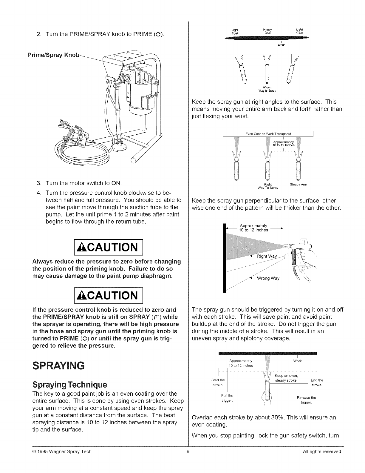
2. Turn the PRIME/SPRAY knob to PRIME (O).
Prime/Spray Knob---___
.
4.
Turn the motor switch to ON.
Turn the pressure control knob clockwise to be-
tween half and full pressure. You should be able to
see the paint move through the suction tube to the
pump. Let the unit prime 1 to 2 minutes after paint
begins to flow through the return tube.
I CAUTION 1
Always reduce the pressure to zero before changing
the position of the priming knob. Failure to do so
may cause damage to the paint pump diaphragm.
I CAUTION 1
If the pressure control knob is reduced to zero and
the PRIME/SPRAY knob is still on SPRAY (if') while
the sprayer is operating, there will be high pressure
in the hose and spray gun until the priming knob is
turned to PRIME (O) or until the spray gun is trig-
gered to relieve the pressure.
SPRAYING
Spraying Technique
The key to a good paint job is an even coating over the
entire surface. This is done by using even strokes. Keep
your arm moving at a constant speed and keep the spray
gun at a constant distance from the surface. The best
spraying distance is 10 to 12 inches between the spray
tip and the surface.
L_jt-I I-,,A_). Lqhl
I
AIii. ;1: "!
i '1
iiI. ._
/i!', ' U
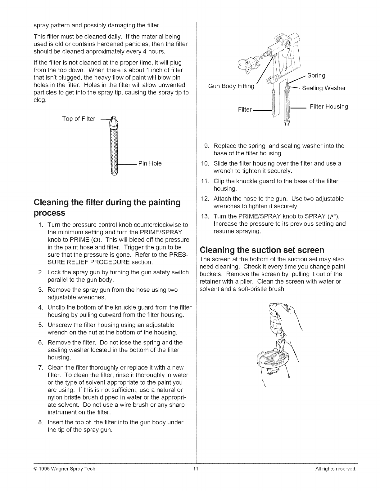
Keep the spray gun at right angles to the surface. This
means moving your entire arm back and forth rather than
just flexing your wrist.
Even Coat on Work Throughout
Right Steady Arm
Way To Spray
Keep the spray gun perpendicular to the surface, other-
wise one end of the pattern will be thicker than the other.
Approximately
10 to 12 Inches
\
_ Wrong Way
The spray gun should be triggered by turning it on and off
with each stroke. This will save paint and avoid paint
buildup at the end of the stroke. Do not trigger the gun
during the middle of a stroke. This will result in an
uneven spray and splotchy coverage.
I I
Approximately Work
10 to 12 inches
p ,
Start the
stroke.
Keep an even, |
steady stroke. / End the
stroke.
Pult the Release the
trigger, trigger.
Overlap each stroke by about 30%. This will ensure an
even coating.
When you stop painting, lock the gun safety switch, turn
© 1995 Wagner Spray Tech 9 All rights reserved.

the pressure control knob counterclockwise to its lowest
setting and set the priming knob to PRIME (©). Turn the
motor switch to OFF and unplug the sprayer.
If you expect to be gone more than 1 hour, follow the
short term clean up procedure described in the
CLEANUP section of this manual.
Practice
.Be sure that the paint hose is free of kinks and clear
of objects with sharp cutting edges.
2. Turn the pressure control knob counterclockwise to
its to its lowest setting.
3. Turn the PRIME/SPRAY knob to SPRAY (F_).
PRIME/SPRAYKNOB
.
.
.
7.
.
Turn the pressure control knob clockwise to its
highest setting. The paint hose should stiffen as
paint begins to flow through it.
Unlock the gun safety switch by turning the switch
so that it is parallel to the handle.
Trigger the spray gun to bleed air out of the hose.
When paint reaches the spray tip, spray a test area
to check the spray pattern.
Use the lowest pressure setting necessary to get a
good spray pattern. If the pressure is set too high,
the spray pattern will be too light. If the pressure is
set too low, tailing will appear or the paint will
spatter out in gobs rather than in a fine spray.
Most latex paints and stains will require very high
pressure, which is why the sprayer is built to deliver
up to 2,500 psi when needed.
Good spray pattern
Paint tailing pattern
If the spray tip becomes clogged
The spray gun is equipped with a reversible tip which
allows you to blow out any particles of old paint or other
contaminants that may obstruct the paint flow through the
tip. If the spray pattern becomes distorted or stops
completely while the gun is triggered on, follow these
steps:
1. Release the trigger and lock the gun by turning the
gun safety switch so that it is parallel to the gun
body.
2. Rotate the reversible tip cylinder arrow 180° so that
the point of the arrow is toward the rear of the gun.
3. Unlock the trigger and squeeze it open, pointing the
gun at a scrap piece of wood or cardboard. This
allows pressure in the paint hose to blow out the
obstruction. When the nozzle is clean, paint will
come out in a straight, high pressure stream.
4. Release the trigger and re-lock it. Figure 4
5. Reverse the tip so the arrow points forward again.
6. Unlock the trigger and resume spraying.
Cleaning the spray gun filter
The spray gun includes a filter to catch particles before
they reach the spray tip. If this filter becomes clogged or
obstructed it will reduce the flow of paint, changing the
© 1995 Wagner Spray Tech 10 All rights reserved.
spray pattern and possibly damaging the filter.
This filter must be cleaned daily. If the material being
used is old or contains hardened particles, then the filter
should be cleaned approximately every 4 hours.
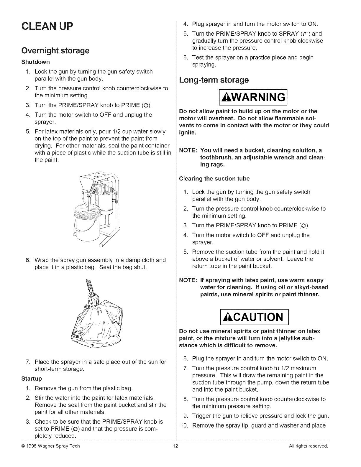
If the filter is not cleaned at the proper time, it will plug
from the top down. When there is about 1 inch of filter
that isn't plugged, the heavy flow of paint will blow pin
holes in the filter. Holes in the filter will allow unwanted
particles to get into the spray tip, causing the spray tip to
clog.
Top of Filter
Pin Hole
Cleaning the filter during the painting
process
.Turn the pressure control knob counterclockwise to
the minimum setting and turn the PRIME/SPRAY
knob to PRIME (O). This will bleed off the pressure
in the paint hose and filter. Trigger the gun to be
sure that the pressure is gone. Refer to the PRES-
SURE RELIEF PROCEDURE section.
2. Lock the spray gun by turning the gun safety switch
parallel to the gun body.
3. Remove the spray gun from the hose using two
adjustable wrenches.
4. Unclip the bottom of the knuckle guard from the filter
housing by pulling outward from the filter housing.
5. Unscrew the filter housing using an adjustable
wrench on the nut at the bottom of the housing.
6. Remove the filter. Do not lose the spring and the
sealing washer located in the bottom of the filter
housing.
7. Clean the filter thoroughly or replace it with a new
filter. To clean the filter, rinse it thoroughly in water
or the type of solvent appropriate to the paint you
are using. If this is not sufficient, use a natural or
nylon bristle brush dipped in water or the appropri-
ate solvent. Do not use a wire brush or any sharp
instrument on the filter.
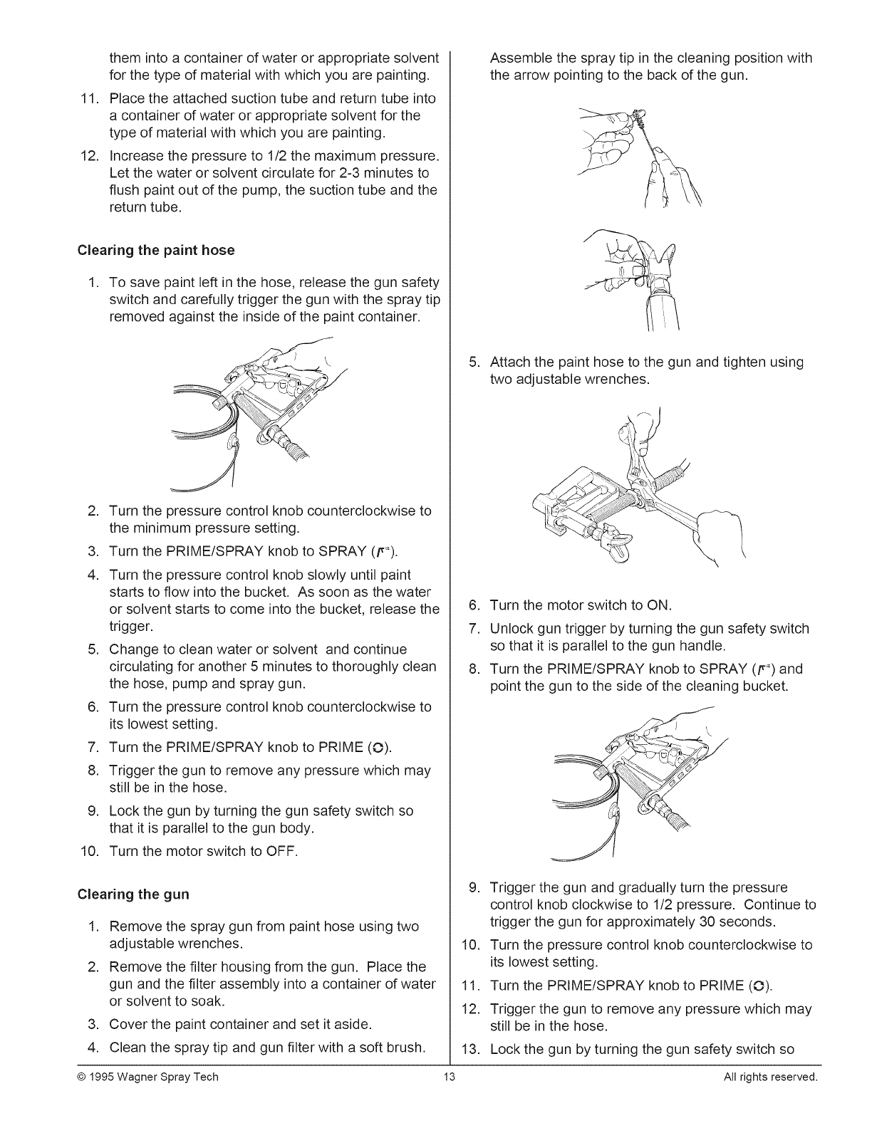
8. Insert the top of the filter into the gun body under
the tip of the spray gun.
Gun Body Fitting Sealing Washer
Filter Filter Housing
9. Replace the spring and sealing washer into the
base of the filter housing.
10. Slide the filter housing over the filter and use a
wrench to tighten it securely.
11. Clip the knuckle guard to the base of the filter
housing.
12. Attach the hose to the gun. Use two adjustable
wrenches to tighten it securely.
13. Turn the PRIME/SPRAY knob to SPRAY (ff_).
Increase the pressure to its previous setting and
resume spraying.
Cleaning the suction set screen
The screen at the bottom of the suction set may also
need cleaning. Check it every time you change paint
buckets. Remove the screen by pulling it out of the
retainer with a plier. Clean the screen with water or
solvent and a soft-bristle brush.
© 1995 Wagner Spray Tech 11 All rights reserved.
CLEAN UP
Overnight storage
Shutdown
1. Lock the gun by turning the gun safety switch
parallel with the gun body.
2. Turn the pressure control knob counterclockwise to
the minimum setting.
3. Turn the PRIME/SPRAY knob to PRIME (O).
4. Turn the motor switch to OFF and unplug the
sprayer.
5. For latex materials only, pour 1/2 cup water slowly
on the top of the paint to prevent the paint from
drying. For other materials, seal the paint container
with a piece of plastic while the suction tube is still in
the paint.
6. Wrap the spray gun assembly in a damp cloth and
place it in a plastic bag. Seal the bag shut.
7. Place the sprayer in a safe place out of the sun for
short-term storage.
Startup
1. Remove the gun from the plastic bag.
2. Stir the water into the paint for latex materials.
Remove the seal from the paint bucket and stir the
paint for all other materials.
3. Check to be sure that the PRIME/SPRAY knob is
set to PRIME (O) and that the pressure is com-
pletely reduced.
© 1995 Wagner Spray Tech
4. Plug sprayer in and turn the motor switch to ON.
5. Turn the PRIME/SPRAY knob to SPRAY (F) and
gradually turn the pressure control knob clockwise
to increase the pressure.
6. Test the sprayer on a practice piece and begin
spraying.
Long-term storage
I, WARNINGI
Do not allow paint to build up on the motor or the
motor will overheat. Do not allow flammable sol-
vents to come in contact with the motor or they could
ignite.
NOTE: You will need a bucket, cleaning solution, a
toothbrush, an adjustable wrench and clean-
ing rags.
Clearing the suction tube
1. Lock the gun by turning the gun safety switch
parallel with the gun body.
2. Turn the pressure control knob counterclockwise to
the minimum setting.
3. Turn the PRIME/SPRAY knob to PRIME (O).
4. Turn the motor switch to OFF and unplug the
sprayer.
5. Remove the suction tube from the paint and hold it
above a bucket of water or solvent. Leave the
return tube in the paint bucket.
NOTE: If spraying with latex paint, use warm soapy
water for cleaning. If using oil or alkyd-based
paints, use mineral spirits or paint thinner.
I CAUTION I
Do not use mineral spirits or paint thinner on latex
paint, or the mixture will turn into a jellylike sub-
stance which is difficult to remove.
,
7.
,
,
10.
Plug the sprayer in and turn the motor switch to ON.
Turn the pressure control knob to 1/2 maximum
pressure. This will draw the remaining paint in the
suction tube through the pump, down the return tube
and into the paint bucket.
Turn the pressure control knob counterclockwise to
the minimum pressure setting.
Trigger the gun to relieve pressure and lock the gun.
Remove the spray tip, guard and washer and place
12 All rights reserved.
11.
12.
them into a container of water or appropriate solvent
for the type of material with which you are painting.
Place the attached suction tube and return tube into
a container of water or appropriate solvent for the
type of material with which you are painting.
Increase the pressure to 1/2 the maximum pressure.
Let the water or solvent circulate for 2-3 minutes to
flush paint out of the pump, the suction tube and the
return tube.
Clearing the paint hose
,
,
,
4.
To save paint left in the hose, release the gun safety
switch and carefully trigger the gun with the spray tip
removed against the inside of the paint container.
Turn the pressure control knob counterclockwise to
the minimum pressure setting.
Turn the PRIME/SPRAY knob to SPRAY (p_).
Turn the pressure control knob slowly until paint
starts to flow into the bucket. As soon as the water
or solvent starts to come into the bucket, release the
trigger.
5. Change to clean water or solvent and continue
circulating for another 5 minutes to thoroughly clean
the hose, pump and spray gun.
6. Turn the pressure control knob counterclockwise to
its lowest setting.
7. Turn the PRIME/SPRAY knob to PRIME (O).
8. Trigger the gun to remove any pressure which may
still be in the hose.
9. Lock the gun by turning the gun safety switch so
that it is parallel to the gun body.
10. Turn the motor switch to OFF.
Clearing the gun
1. Remove the spray gun from paint hose using two
adjustable wrenches.
2. Remove the filter housing from the gun. Place the
gun and the filter assembly into a container of water
or solvent to soak.
3. Cover the paint container and set it aside.
4. Clean the spray tip and gun filter with a soft brush.
,
,
7.
,
Assemble the spray tip in the cleaning position with
the arrow pointing to the back of the gun.
Attach the paint hose to the gun and tighten using
two adjustable wrenches.
Turn the motor switch to ON.
Unlock gun trigger by turning the gun safety switch
so that it is parallel to the gun handle.
Turn the PRIME/SPRAY knob to SPRAY (F _)and
point the gun to the side of the cleaning bucket.
9. Trigger the gun and gradually turn the pressure
control knob clockwise to 1/2 pressure. Continue to
trigger the gun for approximately 30 seconds.
10. Turn the pressure control knob counterclockwise to
its lowest setting.
11. Turn the PRIME/SPRAY knob to PRIME (O).
12. Trigger the gun to remove any pressure which may
still be in the hose.
13.
13
Lock the gun by turning the gun safety switch so
© 1995 Wagner Spray Tech All rights reserved.
that it is parallel to the gun body.
14. Turn the motor switch to OFF.
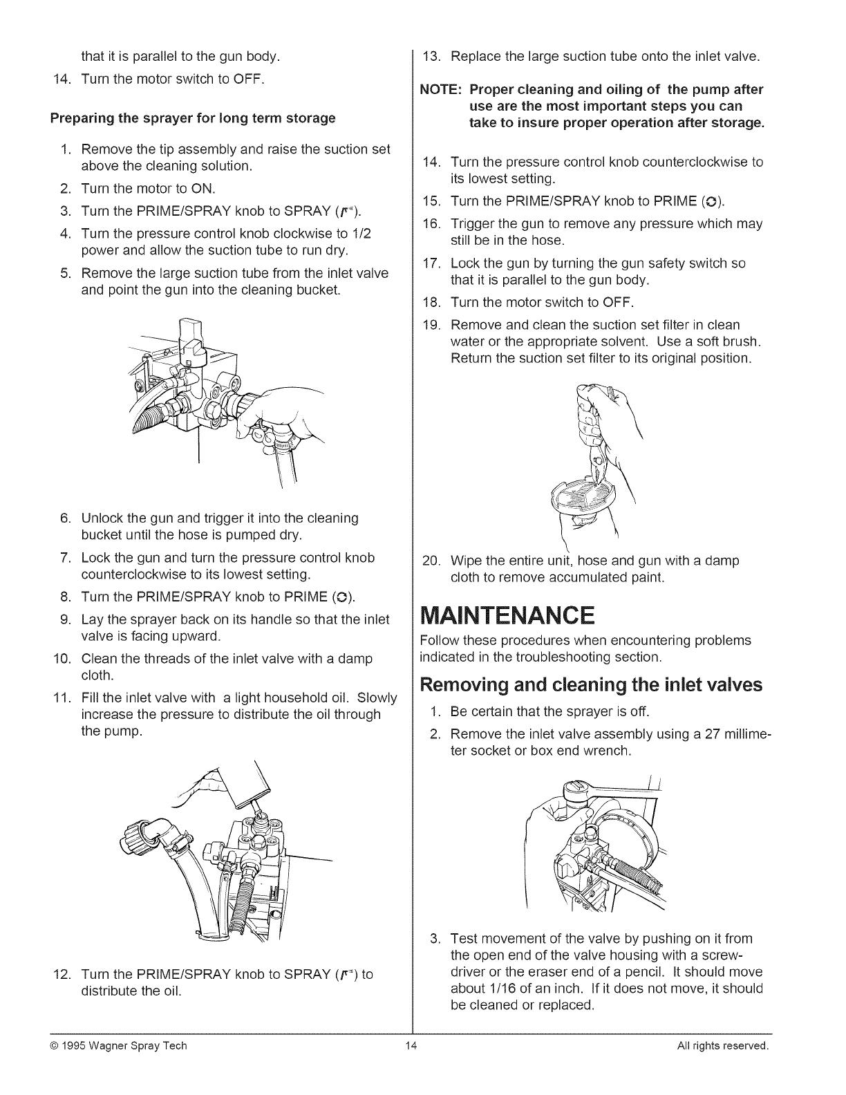
Preparing the sprayer for long term storage
.
.
3.
4.
.
Remove the tip assembly and raise the suction set
above the cleaning solution.
Turn the motor to ON.
Turn the PRIME/SPRAY knob to SPRAY (F_).
Turn the pressure control knob clockwise to 1/2
power and allow the suction tube to run dry.
Remove the large suction tube from the inlet valve
and point the gun into the cleaning bucket.
.Unlock the gun and trigger it into the cleaning
bucket until the hose is pumped dry.
7. Lock the gun and turn the pressure control knob
counterclockwise to its lowest setting.
8. Turn the PRIME/SPRAY knob to PRIME (O).
9. Lay the sprayer back on its handle so that the inlet
valve is facing upward.
10. Clean the threads of the inlet valve with a damp
cloth.
11. Fill the inlet valve with a light household oil. Slowly
increase the pressure to distribute the oil through
the pump.
12. Turn the PRIME/SPRAY knob to SPRAY (p_) to
distribute the oil.
13. Replace the large suction tube onto the inlet valve.
NOTE: Proper cleaning and oiling of the pump after
use are the most important steps you can
take to insure proper operation after storage.
14. Turn the pressure control knob counterclockwise to
its lowest setting.
15. Turn the PRIME/SPRAY knob to PRIME (O).
16. Trigger the gun to remove any pressure which may
still be in the hose.
17.
18.
19.
Lock the gun by turning the gun safety switch so
that it is parallel to the gun body.
Turn the motor switch to OFF.
Remove and clean the suction set filter in clean
water or the appropriate solvent. Use a soft brush.
Return the suction set filter to its original position.
\
20. Wipe the entire unit, hose and gun with a damp
cloth to remove accumulated paint.
MAINTENANCE
Follow these procedures when encountering problems
indicated in the troubleshooting section.
Removing and cleaning the inlet valves
1. Be certain that the sprayer is off.
2. Remove the inlet valve assembly using a 27 millime-
ter socket or box end wrench.
.Test movement of the valve by pushing on it from
the open end of the valve housing with a screw=
driver or the eraser end of a pencil. It should move
about 1/16 of an inch. If it does not move, it should
be cleaned or replaced.
© 1995 Wagner Spray Tech 14 All rights reserved.
NOTE: The inlet valve must be oiled after every job.
This will reduce or eliminate priming prob-
lems the next time the sprayer is used.
,
,
,
Thoroughly clean the valve assembly with water or
the appropriate solvent. Use a small brush.
If you have properly cleaned the valve and water
drips out of the bottom, the valve is worn and needs
to be replaced. A properly seated valve filled with
water and held vertically will not drip.
Install a new or cleaned valve in the pump block and
then fill the valve with light oil or solvent.
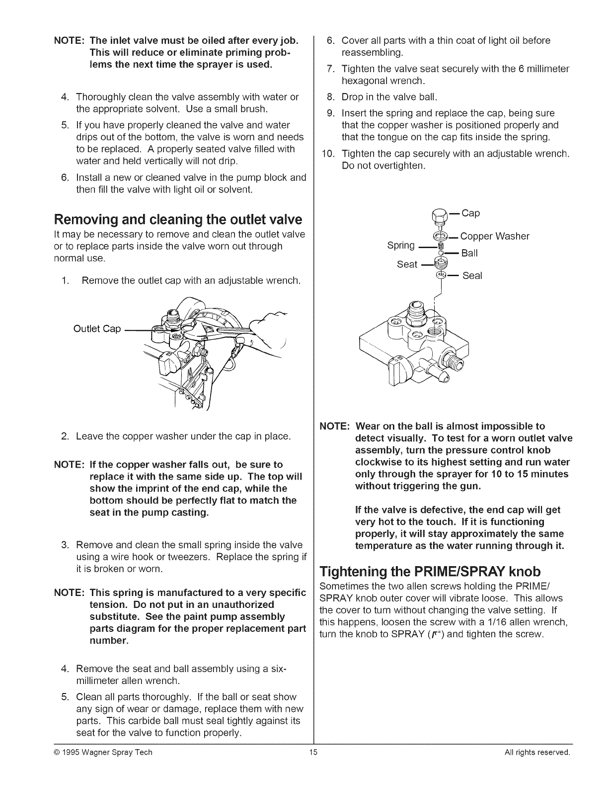
Removing and cleaning the outlet valve
It may be necessary to remove and clean the outlet valve
or to replace parts inside the valve worn out through
normal use.
1. Remove the outlet cap with an adjustable wrench.
Outlet Cap
2. Leave the copper washer under the cap in place.
NOTE: If the copper washer falls out, be sure to
replace it with the same side up. The top will
show the imprint of the end cap, while the
bottom should be perfectly flat to match the
seat in the pump casting.
3. Remove and clean the small spring inside the valve
using a wire hook or tweezers. Replace the spring if
it is broken or worn.
NOTE: This spring is manufactured to a very specific
tension. Do not put in an unauthorized
substitute. See the paint pump assembly
parts diagram for the proper replacement part
number.
,
,
Remove the seat and ball assembly using a six-
millimeter allen wrench.
Clean all parts thoroughly. If the ball or seat show
any sign of wear or damage, replace them with new
parts. This carbide ball must seal tightly against its
seat for the valve to function properly.
6. Cover all parts with a thin coat of light oil before
reassembling.
7. Tighten the valve seat securely with the 6 millimeter
hexagonal wrench.
8. Drop in the valve ball.
9. Insert the spring and replace the cap, being sure
that the copper washer is positioned properly and
that the tongue on the cap fits inside the spring.
10. Tighten the cap securely with an adjustable wrench.
Do not overtighten.
B Cap
_m Copper Washer
Spring _I I Ball
Seat m! _'_
_'_m Seal
NOTE: Wear on the ball is almost impossible to
detect visually. To test for a worn outlet valve
assembly, turn the pressure control knob
clockwise to its highest setting and run water
only through the sprayer for 10 to 15 minutes
without triggering the gun.
If the valve is defective, the end cap will get
very hot to the touch. If it is functioning
properly, it will stay approximately the same
temperature as the water running through it.
Tightening the PRIME/SPRAY knob
Sometimes the two allen screws holding the PRIME/
SPRAY knob outer cover will vibrate loose. This allows
the cover to turn without changing the valve setting. If
this happens, loosen the screw with a 1/16 allen wrench,
turn the knob to SPRAY (F") and tighten the screw.
© 1995 Wagner Spray Tech 15 All rights reserved.

©1995WagnerSprayTech 16 Allrightsreserved.
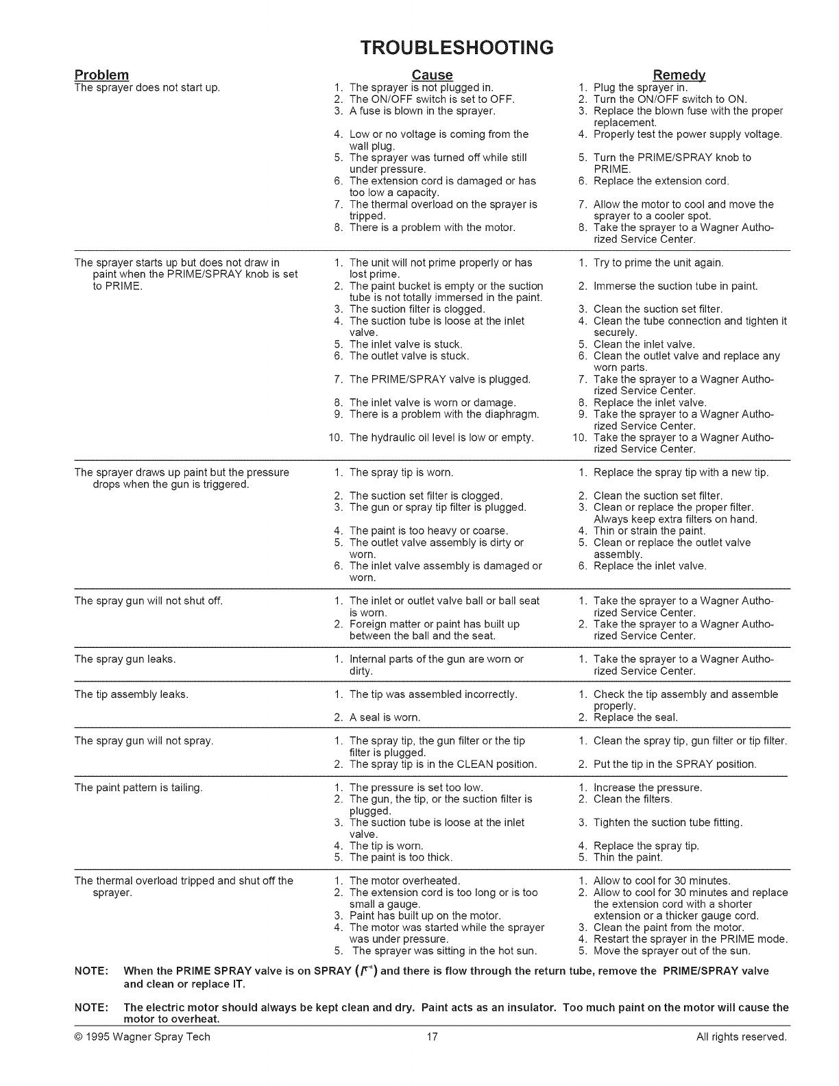
TROUBLESHOOTING
Problem
The sprayer does not start up.
Cause
1. The sprayer is not plugged in. 1.
2. The ON/OFF switch is set to OFF. 2.
3. A fuse is blown in the sprayer. 3.
4. Low or no voltage is coming from the 4.
wall plug.
5. The sprayer was turned offwhile still 5.
under pressure.
6. The extension cord is damaged or has 6.
too low a capacity.
7. The thermal overload on the sprayer is 7.
tripped.
8. There is a problem with the motor. 8.
Remedy
Plug the sprayer in.
Turn the ON/OFF switch to ON.
Replace the blown fuse with the proper
replacement.
Properly test the power supply voltage.
Turn the PRIME/SPRAY knob to
PRIME.
Replace the extension cord.
Allow the motor to cool and move the
sprayer to a cooler spot.
Take the sprayer to a Wagner Autho-
rized Service Center.
The sprayer starts up but does not draw in
paint when the PRIME/SPRAY knob is set
to PRIME.
1. The unit will not prime properly or has 1. Try to prime the unit again.
lost prime.
2. The paint bucket is empty or the suction 2. immerse the suction tube in paint.
tube is not totally immersed in the paint.
3. The suction filter is clogged. 3. Clean the suction set filter.
4. The suction tube is loose at the inlet 4. Clean the tube connection and tighten it
valve, securely.
5. The inlet valve is stuck. 5. Clean the inlet valve.
6. The outlet valve is stuck. 6. Clean the outlet valve and replace any
worn parts.
7. The PRIME/SPRAY valve is plugged. 7. Take the sprayer to aWagner Autho-
rized Service Center.
8. The inlet valve is worn or damage. 8. Replace the inlet valve.
9. There is a problem with the diaphragm. 9. Take the sprayer to aWagner Autho-
rized Service Center.
10. The hydraulic oil level is low or empty. 10. Take the sprayer to a Wagner Autho-
rized Service Center.
The sprayer draws up paint but the pressure
drops when the gun is triggered.
1. The spray tip is worn. 1. Replace the spray tip with a new tip.
2. The suction set filter is clogged. 2. Clean the suction set filter.
3. The gun or spray tip filter is plugged. 3. Clean or replace the proper filter.
Always keep extra filters on hand.
4. The paint is too heavy or coarse. 4. Thin or strain the paint.
5. The outlet valve assembly is dirty or 5. Clean or replace the outlet valve
worn. assembly.
6. The inlet valve assembly is damaged or 6. Replace the inlet valve.
worn.
The spray gun will not shut off. 1. The inlet or outlet valve ball or ball seat 1. Take the sprayer to a Wagner Autho-
is worn. rized Service Center.
2. Foreign matter or paint has built up 2. Take the sprayer to a Wagner Autho-
between the bail and the seat. rized Service Center.
The spray gun leaks. 1. internal parts of the gun are worn or 1. Take the sprayer to a Wagner Autho-
dirty, rized Service Center.
The tip assembly leaks. 1. The tip was assembled incorrectly. 1. Check the tip assembly and assemble
properly.
2. A seal is worn. 2. Replace the seal.
The spray gun will not spray. 1. The spray tip, the gun filter or the tip 1. Clean the spray tip, gun filter or tip filter.
filter is plugged.
2. The spray tip is in the CLEAN position. 2. Put the tip in the SPRAY position.
The paint pattern is tailing. 1. The pressure is set too low. 1. increase the pressure.
2. The gun, the tip, or the suction filter is 2. Clean the filters.
plugged.
3. The suction tube is loose at the inlet 3.
valve.
4. The tip is worn. 4.
5. The paint is too thick. 5.
Tighten the suction tube fitting.
Replace the spray tip.
Thin the paint.
The thermal overload tripped and shut off the
sprayer.
1. The motor overheated.
2. The extension cord is too long or is too
small a gauge.
3. Paint has built up on the motor.
4. The motor was started while the sprayer
was under pressure.
5. The sprayer was sitting in the hot sun.
1. Allow to cool for 30 minutes.
2. Allow to cool for 30 minutes and replace
the extension cord with a shorter
extension or a thicker gauge cord.
3. Clean the paint from the motor.
4. Restart the sprayer in the PRIME mode.
5. Move the sprayer out of the sun.
NOTE: When the PRIME SPRAY valve is on SPRAY (F _) and there is flow through the return tube, remove the PRIME/SPRAY valve
and clean or replace IT,
NOTE: The electric motor should always be kept clean and dry, Paint acts as an insulator, Too much paint on the motor will cause the
motor to overheat,
@ 1995 Wagner Spray Tech 17 All rights reserved.
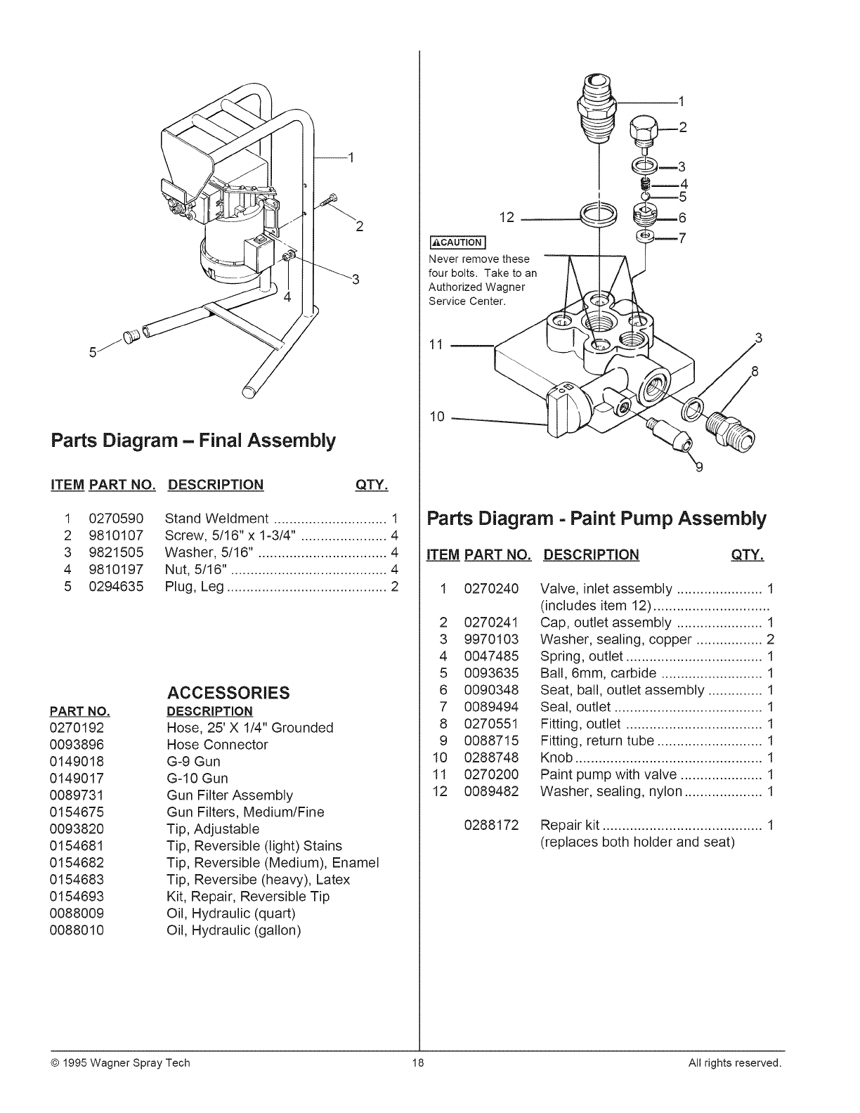
2
Parts Diagram - Final Assembly
iTEM PART NO.
1 0270590
2 9810107
3 9821505
4 9810197
5 0294635
DESCRIPTION QTY.
Stand Weldment ............................. 1
Screw, 5/16"x 1-3/4". ..................... 4
Washer, 5/16". ................................ 4
Nut, 5/16". ....................................... 4
Plug, Leg ......................................... 2
PART NO.
0270192
0093896
0149018
0149017
0089731
0154675
0093820
0154681
0154682
0154683
0154693
0088009
0088010
ACCESSORIES
DESCRIPTION
Hose, 25'X 1/4" Grounded
Hose Connector
G-9 Gun
G-10 Gun
Gun Filter Assembly
Gun Filters, Medium/Fine
Tip, Adjustable
Tip, Reversible (light) Stains
Tip, Reversible (Medium), Enamel
Tip, Reversibe (heavy), Latex
Kit, Repair, Reversible Tip
Oil, Hydraulic (quart)
Oil, Hydraulic (gallon)
12
Never remove these
four bolts. Take to an
Authorized Wagner
Service Center.
10
Parts Diagram -Paint Pump Assembly
ITEM PART NO. DESCRIPTION QTY.
0270240
2 0270241
3 9970103
4 0047485
5 0093635
6 0090348
7 0089494
8 0270551
9 0088715
10 0288748
11 0270200
12 0089482
Valve, inlet assembly ...................... 1
(includes item 12) ..............................
Cap, outlet assembly ...................... 1
Washer, sealing, copper ................. 2
Spring, outlet ................................... 1
Ball, 6mm, carbide .......................... 1
Seat, ball, outlet assembly .............. 1
Seal, outlet ...................................... 1
Fitting, outlet ................................... 1
Fitting, return tube ........................... 1
Knob ................................................ 1
Paint pump with valve ..................... 1
Washer, sealing, nylon .................... 1
0288172 Repair kit ......................................... 1
(replaces both holder and seat)
© 1995 Wagner Spray Tech 18 All rights reserved.
3
5
6B1
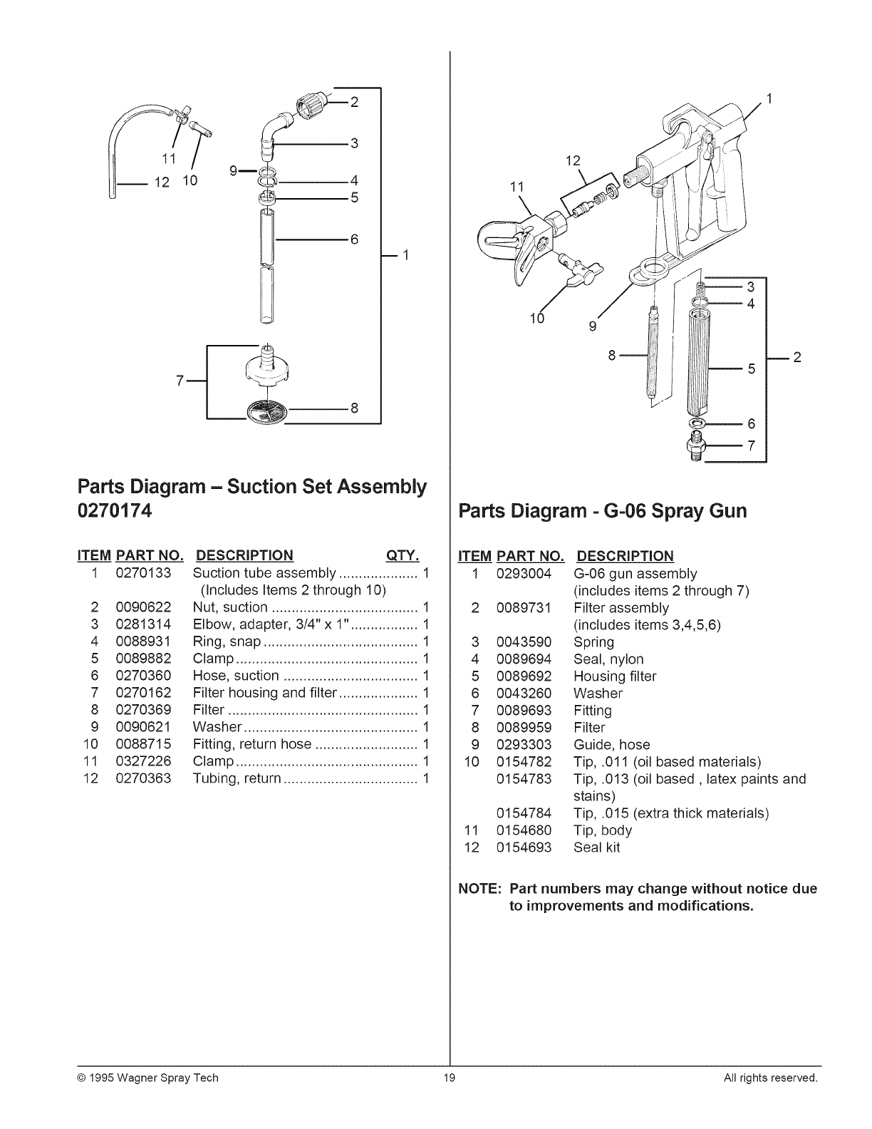
Parts Diagram - Suction Set Assembly
0270174
iTEM PART NO.
1 0270133
2 0090622
3 0281314
4 0088931
5 0089882
6 0270360
7 0270162
8 0270369
9 0090621
10 0088715
11 0327226
12 0270363
DESCRiPTiON QTY.
Suction tube assembly .................... 1
(Includes Items 2 through 10)
Nut, suction ..................................... 1
Elbow, adapter, 3/4" x 1". ................ 1
Ring, snap ....................................... 1
Clamp .............................................. 1
Hose, suction .................................. 1
Filter housing and filter .................... 1
Filter ................................................ 1
Washer ............................................ 1
Fitting, return hose .......................... 1
Clamp .............................................. 1
Tubing, return .................................. 1
12
11
10 9
8m2
Parts Diagram =G=06 Spray Gun
iTEM PART NO. DESCRiPTiON
1 0293004 G-06gun assembly
(includes items 2 through 7)
2 0089731 Filter assembly
(includes items 3,4,5,6)
3 0043590 Spring
4 0089694 Seal, nylon
5 0089692 Housing filter
6 0043260 Washer
7 0089693 Fitting
8 0089959 Filter
9 0293303 Guide, hose
10 0154782 Tip, .011 (oil based materials)
0154783 Tip, .013 (oil based, latex paints and
stains)
0154784 Tip, .015 (extra thick materials)
11 0154680 Tip, body
12 0154693 Seal kit
NOTE: Part numbers may change without notice due
to improvements and modifications.
© 1995 Wagner Spray Tech 19 All rights reserved.
LiMiTED WARRANTY
AIRLESS PAINT SPRAY EQUIPMENT
This product, manufactured by Wagner Spray Tech Corporation (Wagner), is warranted to the original retail purchaser
against defects in material and workmanship for 30 days from date of purchase for professional/rental use ifoperated
in accordance with Wagner's printed recommendations and instructions. This warranty applies for one year from date
of purchase for home use.
This warranty does not cover damage resulting from improper use, accidents, user's negligence or normal wear. This
warranty does not cover any defects or damages caused byservice or repair performed by anyone other than a Wagner
Authorized Service Center. This warranty does not apply to accessories.
ANY IMPLIED WARRANTY OF MERCHANTABILITY OR FITNESS FOR A PARTICULAR PURPOSE IS LIMITED
TO 30 DAYS FOR PROFESSIONAL/RENTAL USE AND ONE YEAR FOR HOME USE FROM DATE OF
PURCHASE.
WAGNER SHALL NOT IN ANY EVENT BE LIABLE FOR ANY INCIDENTAL OR CONSEQUENTIAL DAMAGES
OF ANY KIND, WHETHER FROM BREACH OF THIS WARRANTY OR ANY OTHER REASON.
If any product is defective in material and/or workmanship during the applicable warranty period, return it with proof
of purchase, transportation prepaid to any Wagner Authorized Service Center. (Service Center listing is enclosed with
this product.) Wagner's Authorized Service Center will either repair or replace the product (at Wagner's option) and
return it to you, postage prepaid.
SOME STATES DO NOT ALLOW LIMITATIONS ON HOW LONG AN IMPLIED WARRANTY LASTS OR THE
EXCLUSION OF INCIDENTAL OR CONSEQUENTIAL DAMAGES, SO THE ABOVE LIMITATION AND EXCLUSION
MAY NOT APPLY TO YOU.
THIS WARRANTY GIVES YOU SPECIFIC LEGAL RIGHTS, AND YOU MAY ALSO HAVE OTHER RIGHTS WHICH
VARY FROM STATE TO STATE.
Copyright © 1995 Wagner Spray Tech Corporation. All
rights reserved, including right of reproduction in whole or
in part, in any form. Printed in U.S.A.
A
Wagner Spray Tech Corporation
1770 Fernbrook Lane
Minneapolis, Minnesota 55447
Telephone (612) 553=7000
