Walt Disney Parks and Resorts US XBR-S-R1G1 xBR-S-R1G1 User Manual
Walt Disney Parks and Resorts US., INC. xBR-S-R1G1
User Manual

900-000140 Rev 02 xBR V3x2 Installation and User Guide Page 1 of 12
X
BR
V3
X
2
I
NSTALLATION
AND
U
SER
G
UIDE
900-000140 Rev 02 xBR V3x2 Installation and User Guide Page 2 of 12
Revision History
Rev Date Author Description
01 10/02/2012
Eric Anderson Initial release
02 10/16/2012
Eric Anderson & Andrew
Stack
Logo change
Document Approvers & Sign-Off
Date Approver Role Document Accept/Reject

900-000140 Rev 02 xBR V3x2 Installation and User Guide Page 3 of 12
Table of Contents
1 Introduction ............................................................................................................ 4
1.1 Purpose ............................................................................................................ 4
1.2 Definitions ........................................................................................................ 4
1.3 Overview .......................................................................................................... 4
2 Safety Warnings ...................................................................................................... 5
2.1 Important Safety Instructions ............................................................................. 5
2.2 Explosive Safety Warning ................................................................................... 5
2.3 Lightning Warning ............................................................................................. 5
3 Regulatory Compliance ............................................................................................. 6
3.1 Federal Communications Commission (United States) ............................................ 6
3.2 UL Certification .................................................................................................. 6
4 Specifications .......................................................................................................... 7
4.1 Physical ............................................................................................................ 7
4.2 Connection Ports (per internal module) ................................................................ 8
4.3 RF Frequencies .................................................................................................. 8
4.4 Operating Conditions .......................................................................................... 8
4.5 Power (per internal module) ............................................................................... 8
5 Installation ............................................................................................................. 9
5.1 Trained Installation and Service Personnel Warning ............................................... 9
5.2 Electrostatic Discharge Warning .......................................................................... 9
5.3 Telecom Warning ............................................................................................... 9
5.4 Installation Instructions .................................................................................... 10
6 Connection Guide .................................................................................................. 11
900-000140 Rev 02 xBR V3x2 Installation and User Guide Page 4 of 12
1 Introduction
The Synapse xBR V3x2 xTable Reader is part of a proprietary data acquisition and tracking
system. It provides transmitters and multiple receivers to collect data, which can be then
sent over Ethernet connections to a data collection/concentration object.
1.1 Purpose
This document provides basic installation and user instructions for the Synapse xBR
V3x2 xTable Reader.
1.2 Definitions
Term Definition
PoE Power over Ethernet
PCA Printed circuit assembly
1.3 Overview
The xBR V3x2 consists of 2 individual xBR PCAs mounted in an aluminum enclosure. The
2 PCAs are functionally separate, each having its own antennas, power supply
connection, Ethernet connections, and MAC address. The connections on the unit are
designated A and B to specify to which internal xBR unit they belong. The enclosure is
labeled with the MAC addresses of both the xBR PCAs.

900-000140 Rev 02 xBR V3x2 Installation and User Guide Page 5 of 12
2 Safety Warnings
2.1 Important Safety Instructions
When using this device, basic safety precautions should always be followed to reduce
the risk of fire, electric shock and injury to persons.
Do not use this product near water. For example, do not use:
• near a bathtub
• near a wash bowl
• near a kitchen sink or laundry tub
• in a wet basement
• near a swimming pool
2.2 Explosive Safety Warning
Warning! Do not operate this device near explosive devices, unshielded blasting caps
or in an otherwise explosive environment unless the device has been approved for such
use by qualified personnel.
Warning! Do not disconnect the power or any other cabling in an explosive
environment until such qualified personnel, trained specifically in explosive environment
handling, have determined it is safe to do so.
Warning! Do not touch or move the device when the antennas are transmitting or
receiving.
2.3 Lightning Warning
Warning! Do not connect or disconnect cables or otherwise work with the device
hardware during periods of lightning activity.
Avoid using this product during an electrical storm. There may be a remote risk of
electric shock from lightning.

900-000140 Rev 02 xBR V3x2 Installation and User Guide Page 6 of 12
3 Regulatory Compliance
3.1 Federal Communications Commission (United States)
Regulatory Compliance Information
This device complies with part 15 of the FCC Rules. Operation is subject to the following
two conditions: (1) This device may not cause harmful interference, and (2) this device
must accept any interference received, including interference that may cause undesired
operation.
RF Exposure Statement
The device has been found to be compliant to the requirements set forth in CFR 47
Sections 2.1091 for an uncontrolled environment. The antenna(s) used for this
transmitter must be installed to provide a separation distance of at least 35 cm from all
persons and must not be co-located or operating in conjunction with any other antenna
or transmitter.
Caution
Any changes or modifications not expressly approved by Synapse Product Development
could void the user’s authority to operate this equipment.
3.2 UL Certification
UL permission to list has been applied for, but has not yet been granted.
900-000140 Rev 02 xBR V3x2 Installation and User Guide Page 7 of 12
4 Specifications
The Synapse xBR V3x2 Long Range Reader is manufactured to the following specifications:
4.1 Physical
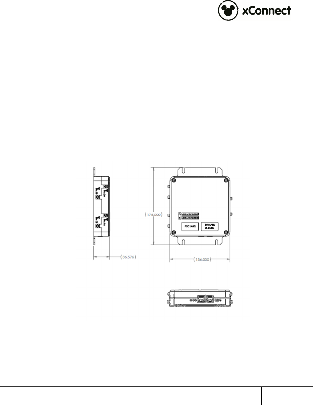
xBR Assembly, PN: 300-001311 (Figure 1)
• Housing Material: Aluminum
• Dimensions:
Length: 176 mm
Width: 136 mm
Height: 36.6 mm
• Unit Weight: 715 g
Figure 1. xBR V3x2 orthographic views (measurements in millimeters)

900-000140 Rev 02 xBR V3x2 Installation and User Guide Page 8 of 12
4.2 Connection Ports (per internal module)
• Ethernet 10/100 RJ-45 (POE): 100m maximum cable length
• Ethernet 10/100 RJ-45: 100m maximum cable length
• 3 SMA Antennal Ports: 1 transmit, 2 receive
• DC Power Jack: 2.5mm ID, 5.5mm OD, center conductor positive
4.3 RF Frequencies
• RX: 2401, 2424, 2450, 2474 MHz
• TX: 2482 MHz
4.4 Operating Conditions
Temperature:
• Operating: 0°C to 40°C (32°F to 104°F)
• Storage: -10°C to 70°C (14°F to 158°F)
• Relative Humidity: 5% to 95% non-condensing
• Altitude: 8,000 ft @28°C (82.4°F)
4.5 Power (per internal module)
Power over Ethernet (IEEE, 802.3af compliant)
PoE 48V DC, 200 mA
DC Barrel Jack: 20-48V DC, 300mA
NOTE: If a power adapter other than one provided by Synapse Product Development is used in
the US or Canada, it should be cULus (NRTL) Listed, with an output rated 20-48Vdc maximum,
minimum 300mA, Marked “LPS” or “Class 2”, output rated SELV, non-energy hazardous, and
suitable for connection to a standard power receptacle in the US and Canada.

900-000140 Rev 02 xBR V3x2 Installation and User Guide Page 9 of 12
5 Installation
5.1 Trained Installation and Service Personnel Warning
Warning! Installation and service of this product is to be performed by trained
installation and service personnel only. Read and follow all warning notices and
instructions marked on the product or included in the documentation. Before installing
the product, read the rest of this document and follow specific product instructions.
When installing, the placement of the device must also satisfy the following installation
requirements:
• If not operating with PoE (Power over Ethernet), connect the unit’s AC adapter
to an AC wall outlet (100-240 VAC) using only the standard power cord/adapter
provided with the product.
• Placement must allow for easily disconnecting the power cord/adapter of the
device from the AC wall outlet.
• Do not cover the device or block the airflow to the device with any other objects.
• Keep the device away from excessive heat and humidity and keep the device
free from vibration and dust.
• Installation must at all times conform to local regulations.
• Connections to Wireless Access Point can be made with either Unshielded
Twisted Pair (UTP) or Shielded Twisted Pair (STP) cabling.
5.2 Electrostatic Discharge Warning
Warning! Wear an anti-static wrist strap or take other suitable measures to prevent
electrostatic discharge when handling this equipment.
5.3 Telecom Warning
Note: This unit is intended for local (intra-building) connections only and is not
designed or evaluated for direct connections to the public telecommunications/cable
distributions systems. Cable and Ethernet connections should be made in accordance to
the National Electrical Code (NEC). For example, one of the following should be true*:
- Cable runs are located in the same building as this unit.
- Cable runs through air between buildings are less than 42m (140ft).
- Cable runs between buildings are directly buried.
- Cable runs between buildings are in underground conduit, where a continuous metallic
cable shield or a continuous metallic conduit containing the cable is bonded to each
building grounding electrode system.
*These options are from the US National Electrical Code, Sections 800.10, 800.12, 800.13, 800.31,
800.32, 800.33, and 800.40.

900-000140 Rev 02 xBR V3x2 Installation and User Guide Page 10 of 12
5.4 Installation Instructions
This device should be securely mounted to a fixed surface using appropriate connection
hardware suitable for the mounting surface. For example, when mounting on drywall,
use wall anchors, toggle bolts, or expansion anchors to provide more secure
attachment points.
Note: This device is not to be installed in air handling spaces (i.e. not plenum rated).
900-000140 Rev 02 xBR V3x2 Installation and User Guide Page 11 of 12
6 Connection Guide
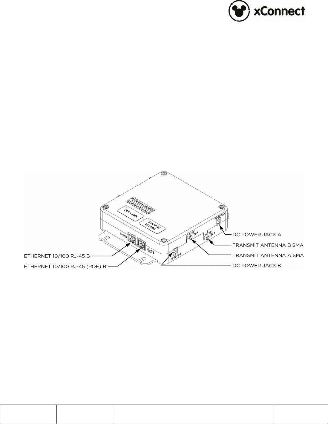
Each module in the xBR V3x2 Long Range Reader has several connection points as shown in
Figure 2 and Figure 3:
Transmit Antenna SMA – This is a female SMA connection for the transmit antenna. The
transmit antenna must be installed at all times when the unit is powered up and
transmitting. Transmitting without the antenna installed may damage the unit.
This antenna must be of an approved or supplied type. Use of an unauthorized antenna is
not allowed.
DC Power Jack – This provides a means of powering the unit if PoE is not available.
Connect only a supplied or an approved power supply.
Figure 2. xBR V3x2 transmit antennas, power jacks, and Ethernet connection points
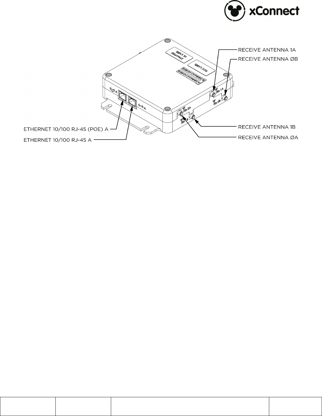
Ethernet 10/100 RJ-45 – This is an RJ-45 jack for an Ethernet connection.
Ethernet 10/100 RJ-45 (PoE) – This is an RJ-45 jack for an Ethernet connection with
optional Power over Ethernet (PoE).
900-000140 Rev 02 xBR V3x2 Installation and User Guide Page 12 of 12
Figure 3. xBR V3x2 receive antennas and Ethernet connection points
Receive Antenna 0 and 1 SMA – These are female SMA connections for the receive
antenna(s).