Walt Disney Parks and Resorts US XTP-R1G1 xTP-R1G1 User Manual xBRC User Interface User Guide
Walt Disney Parks and Resorts US., INC. xTP-R1G1 xBRC User Interface User Guide
User Manual

900-0142
Rev 01
xTP Installation and User Guide
Page 1 of 16
Confidential and Proprietary
XTP INSTALLATION AND USER GUIDE

900-0142
Rev 01
xTP Installation and User Guide
Page 2 of 16
Confidential and Proprietary
Revision History
Rev
Date
Author
Description
01
10/17/2012
Brian Piquette
Initial release
Document Approvers & Sign-Off
Date
Approver
Role
Document Accept/Reject
Patrick Stanko
Project Manager
Brian Piquette
Electrical Engineer
Richard Criado
Product Owner

900-0142
Rev 01
xTP Installation and User Guide
Page 3 of 16
Confidential and Proprietary
Table of Contents
1 Introduction ............................................................................................................ 4
1.1 Purpose ............................................................................................................ 5
1.2 Definitions ........................................................................................................ 5
2 Safety Warnings ...................................................................................................... 6
2.1 Important Safety Instructions ............................................................................. 6
2.2 Explosive Safety Warning ................................................................................... 6
2.3 Lightning Warning ............................................................................................. 6
3 Regulatory Compliance ............................................................................................. 7
3.1 Federal Communications Commission (United States) ............................................ 7
3.2 UL Certification .................................................................................................. 7
4 Specifications .......................................................................................................... 8
4.1 Connection Ports ............................................................................................... 8
4.2 RFID Capabilities ............................................................................................... 8
4.3 Operating Conditions .......................................................................................... 8
4.4 Power .............................................................................................................. 9
4.5 Physical .......................................................................................................... 10
4.5.1 xTPX Module, Available in 4 different color options ......................................... 10
5 Installation ........................................................................................................... 13
5.1 Trained Installation and Service Personnel Warning ............................................. 13
5.2 Electrostatic Discharge Warning ........................................................................ 13
5.3 Telecom Warning ............................................................................................. 13
5.4 Installation Instructions .................................................................................... 14
5.4.1 Generic Stanchion Installation ..................................................................... 14

900-0142
Rev 01
xTP Installation and User Guide
Page 4 of 16
Confidential and Proprietary
1 Introduction
The Synapse xTP Short Range Reader is part of a proprietary data acquisition and tracking
system. It provides an HF RFID reader (TX/RX) to read RFID tag data from proprietary RFID
media. This RFID tag data can be then sent over an Ethernet connection to a data
collection/concentration object. The xTP is designed to be mounted in several known
stanchions which provide the final weather proof enclosure for the product.
The xTP assembly is designed to be mounted in one of several different stanchion designs.
Among the existing stanchion designs are the Park Entry Sphere, multiple themed
stanchions, and several kiosk installations. The diagram below shows the sub-assemblies
that go into the themed stanchion assemblies.

900-0142
Rev 01
xTP Installation and User Guide
Page 5 of 16
Confidential and Proprietary
1.1 Purpose
This document provides basic installation and user instructions for the Synapse xTP
Short Range Reader.
1.2 Definitions
Term
Definition
RFID
Radio Frequency Identification
OTS
Off the shelf
cULus (NRTL)
Canadian & US Underwriters Lab
recognition
(Nationally Recognized Testing Laboratory)

900-0142
Rev 01
xTP Installation and User Guide
Page 6 of 16
Confidential and Proprietary
2 Safety Warnings 2.1 Important Safety Instructions
When using this device, basic safety precautions should always be followed to reduce
the risk of fire, electric shock and injury to persons.
Do not use this product near water. For example, do not use:
near a bath tub
near a wash bowl
near a kitchen sink or laundry tub
in a wet basement
near a swimming pool
2.2 Explosive Safety Warning Warning! Do not operate this device near explosive devices, unshielded blasting caps
or in an otherwise explosive environment unless the device has been approved for such
use by qualified personnel.
Warning! Do not disconnect the power or any other cabling in an explosive
environment until such qualified personnel, trained specifically in explosive environment
handling, have determined it is safe to do so.
2.3 Lightning Warning Warning! Do not connect or disconnect cables or otherwise work with the device
hardware during periods of lightning activity.
Avoid using this product during an electrical storm. There may be a remote risk of
electric shock from lightning.

900-0142
Rev 01
xTP Installation and User Guide
Page 7 of 16
Confidential and Proprietary
3 Regulatory Compliance 3.1 Federal Communications Commission (United States) Regulatory Compliance Information
This device complies with part 15 of the FCC Rules. Operation is subject to the following
two conditions: (1) This device may not cause harmful interference, and (2) this device
must accept any interference received, including interference that may cause undesired
operation.
Caution:
Any changes or modifications not expressly approved by Walt Disney Parks and Resorts
U.S. (WDPR) could void the user’s authority to operate this equipment.
3.2 UL Certification
The xTP has been certified as a UL Recognized Component to the UL 60950-1 standard.
900-0142
Rev 01
xTP Installation and User Guide
Page 8 of 16
Confidential and Proprietary
4 Specifications
The Synapse xTP Short Range Reader is manufactured to the following specifications:
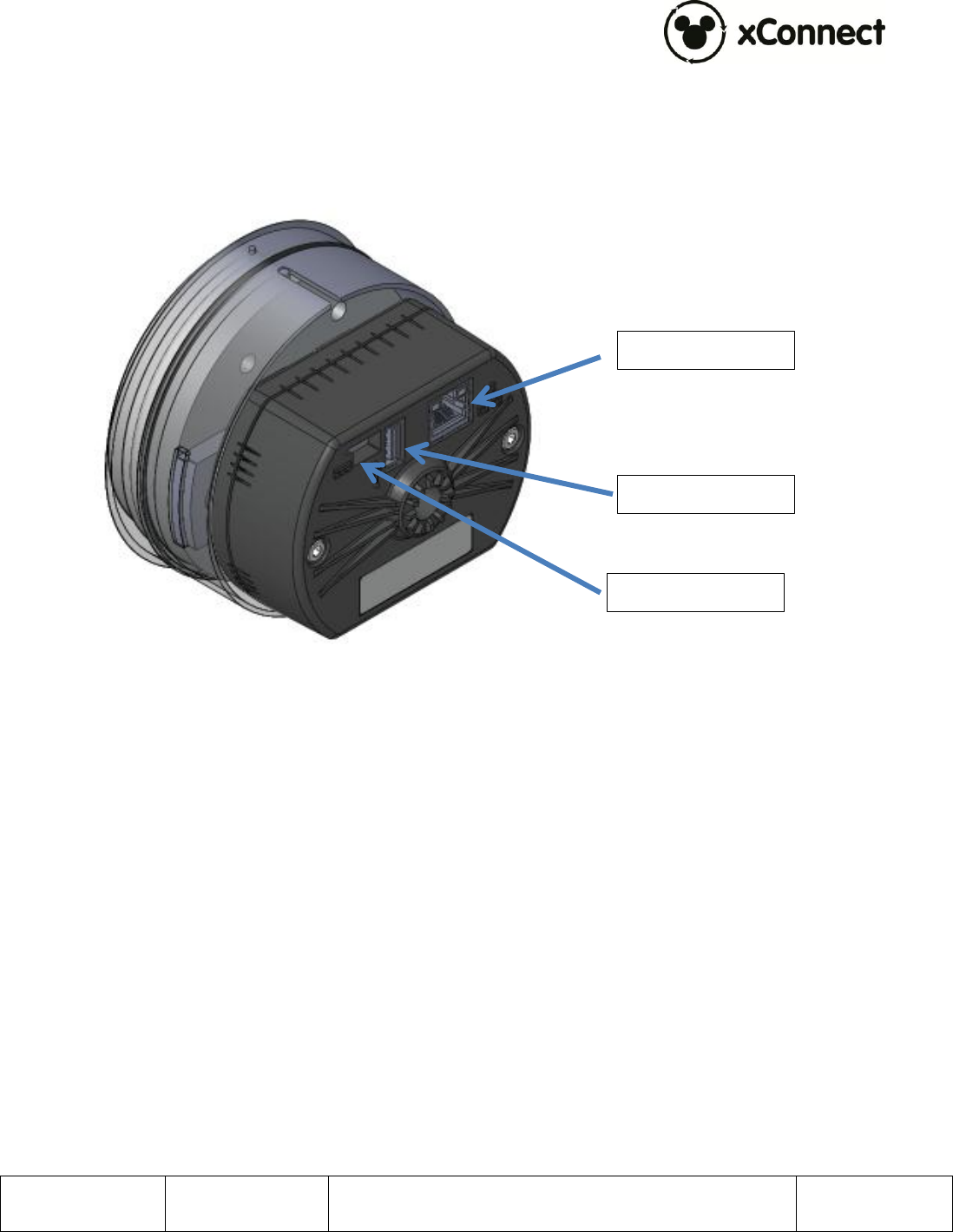
4.1 Connection Ports
Figure 1 – xTP Connections
Ethernet 10/100 RJ-45: 100m Max. cable length
USB-A HS port: USB port for biometric reader peripheral, not intended for OTS
USB peripheral connections.
DC Power Jack: Hirose Part Number RP34L-5R-3PD connector, See Document
604-0016-01 for the mate with connector detail and pinout.
4.2 RFID Capabilities
TX/RX: 13.56 MHz
ISO 14443A, with support for proprietary security protocols
4.3 Operating Conditions
Temperature:
Operating: -10°C to 50°C
Storage: -20°C to 60°C
Operating Relative Humidity: 90% condensing/non-condensing
Ethernet RJ-45
Biometric USB
DC Power Jack

900-0142
Rev 01
xTP Installation and User Guide
Page 9 of 16
Confidential and Proprietary
Altitude: 8,000 ft @28°C (82.4°F)
4.4 Power
DC Input: 24Vdc, 3A max
NOTE: This product must be used with a DC power source that is cULus (NRTL) Listed, with an
output rated 24VDC +/- 20% maximum, minimum 3A , Marked “LPS” or “Class 2”, output rated
SELV, non-energy hazardous and suitable for connection to a standard power receptacle in the
US and Canada.
900-0142
Rev 01
xTP Installation and User Guide
Page 10 of 16
Confidential and Proprietary
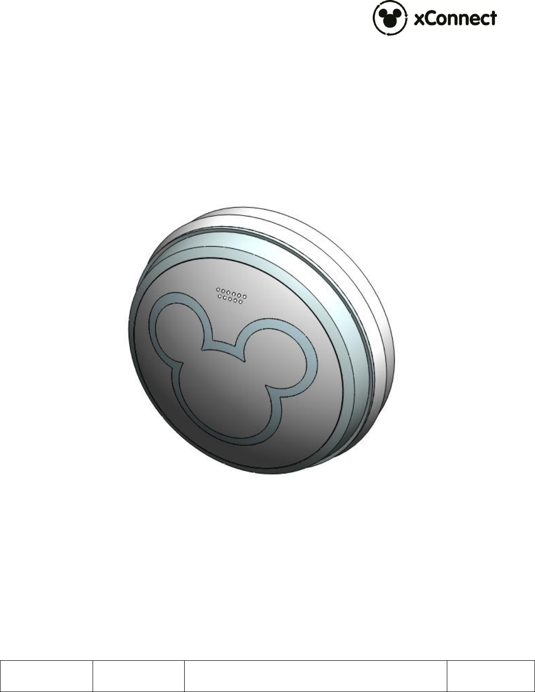
4.5 Physical 4.5.1 xTPX Module, Available in 5 different color options xTPX, PN: 300-001044-xx, 300-001424 (Figure 2)
Plastic face material: Polycarbonate
Dimensions:
Diameter: 99.28mm
Height: 40.96mm
Unit Weight: 360 grams
Figure 2 – xTPX Module
900-0142
Rev 01
xTP Installation and User Guide
Page 11 of 16
Confidential and Proprietary
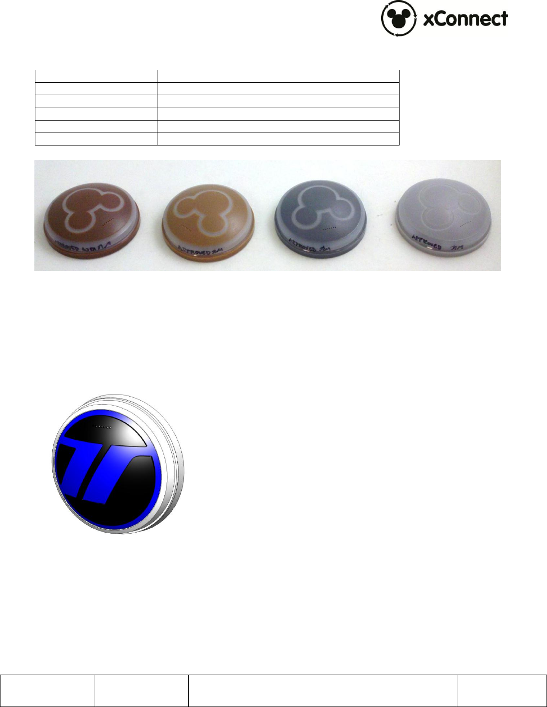
The xTPX is available in 4 different color configurations. The part number details are as
follows:
Part Number
Color Callout
300-001044-01
CWCL 3164M
300-001044-02
Dupont Spectramaster YS146
300-001044-03
Dupont Spectramaster DS 171
300-001044-04
Pantone 464U
300-001424
Test Track Logo Dome
Test Track Logo Dome
DuPont
Spectramaster
YS146
Pantone 464U
Dupont
Spectramaster
DS171
CWCL 3164M

900-0142
Rev 01
xTP Installation and User Guide
Page 13 of 16
Confidential and Proprietary
5 Installation 5.1 Trained Installation and Service Personnel Warning Warning! Installation and service of this product is to be performed by trained
installation and service personnel only. Read and follow all warning notices and
instructions marked on the product or included in the documentation. Before installing
the product, read the rest of this document and follow specific product instructions.
When installing, the placement of the device must also satisfy the following installation
requirements:
Placement must allow for easily disconnecting the power cord/adapter of the
device from the AC wall-outlet.
Keep the device away from excessive heat and humidity and keep the device
free from vibration and dust.
Installation must at all times conform to local regulations.
Network Connections can be made with either Unshielded Twisted Pair (UTP) or
Shielded Twisted Pair (STP) cabling.
5.2 Electrostatic Discharge Warning Warning! Wear an anti-static wrist strap or take other suitable measures to prevent
electrostatic discharge when handling this equipment.
5.3 Telecom Warning
Note: This unit is intended for local (intra-building) connections only and is not
designed or evaluated for direct connections to the public telecommunications/cable
distributions systems. Cable and Ethernet connections should be made in accordance to
the National Electrical Code (NEC). For example, one of the following should be true*:
- Cable runs are located in the same building as this unit.
- Cable runs through air between buildings are less than 42m (140ft).
- Cable runs between buildings are directly buried.
- Cable runs between buildings are in underground conduit, where a continuous metallic
cable shield or a continuous metallic conduit containing the cable is bonded to each
building grounding electrode system.
*These options are from the US National Electrical Code, Sections 800.10, 800.12, 800.13, 800.31, 800.32,
800.33, and 800.40.
900-0142
Rev 01
xTP Installation and User Guide
Page 14 of 16
Confidential and Proprietary
5.4 Installation Instructions
The xTP was designed to be installed in various stanchion/enclosure designs. For detailed
enclosure/stanchion design rules, refer to Document 900-0143, Stanchion Design
Requirements.
5.4.1 Generic Stanchion Installation
The images below show an show the xTP being installed into a stanchion mock up
showing the front face and back wall to demonstrate the steps involved with installation.
An actual stanchion is a full enclosed, sealed enclosure for the xTP.
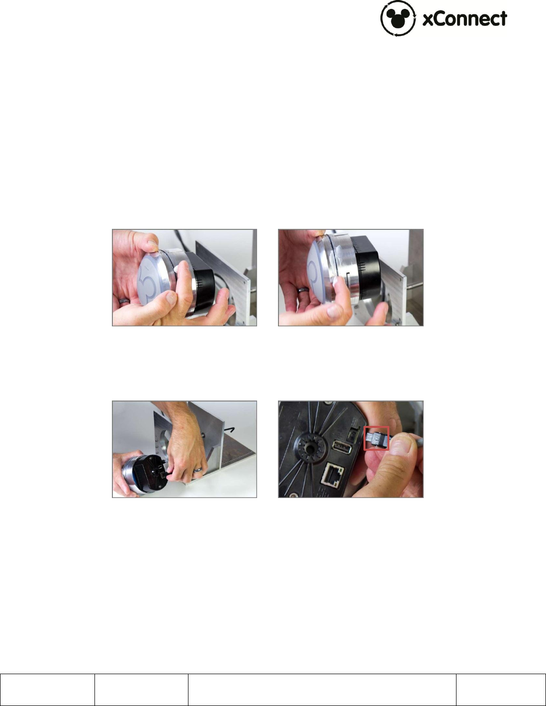
To install the xTP Assembly:
1. Ensure that the Trim Ring O-ring is lubricated with Molykote 55.
Figure 10.5 – Lubricating the Trim Ring
2. Plug in the Ethernet and power lead into the ports at the back of the xTPE. The
arrow on the power lead is facing down.
Figure 10.6 – Plugging in the Ethernet and Power Lead
3. Wait for the Ethernet indicator lights to show connection and activity by blinking.
NOTE: It can take over a minute to connect, once the power is plugged in.

900-0142
Rev 01
xTP Installation and User Guide
Page 15 of 16
Confidential and Proprietary
Figure 10.7 – Ethernet Indicator Lights
4. Orient the Trim Ring pin to the groove in the stanchion (12 o’clock).
Figure 10.8 – Orienting the Trim Ring
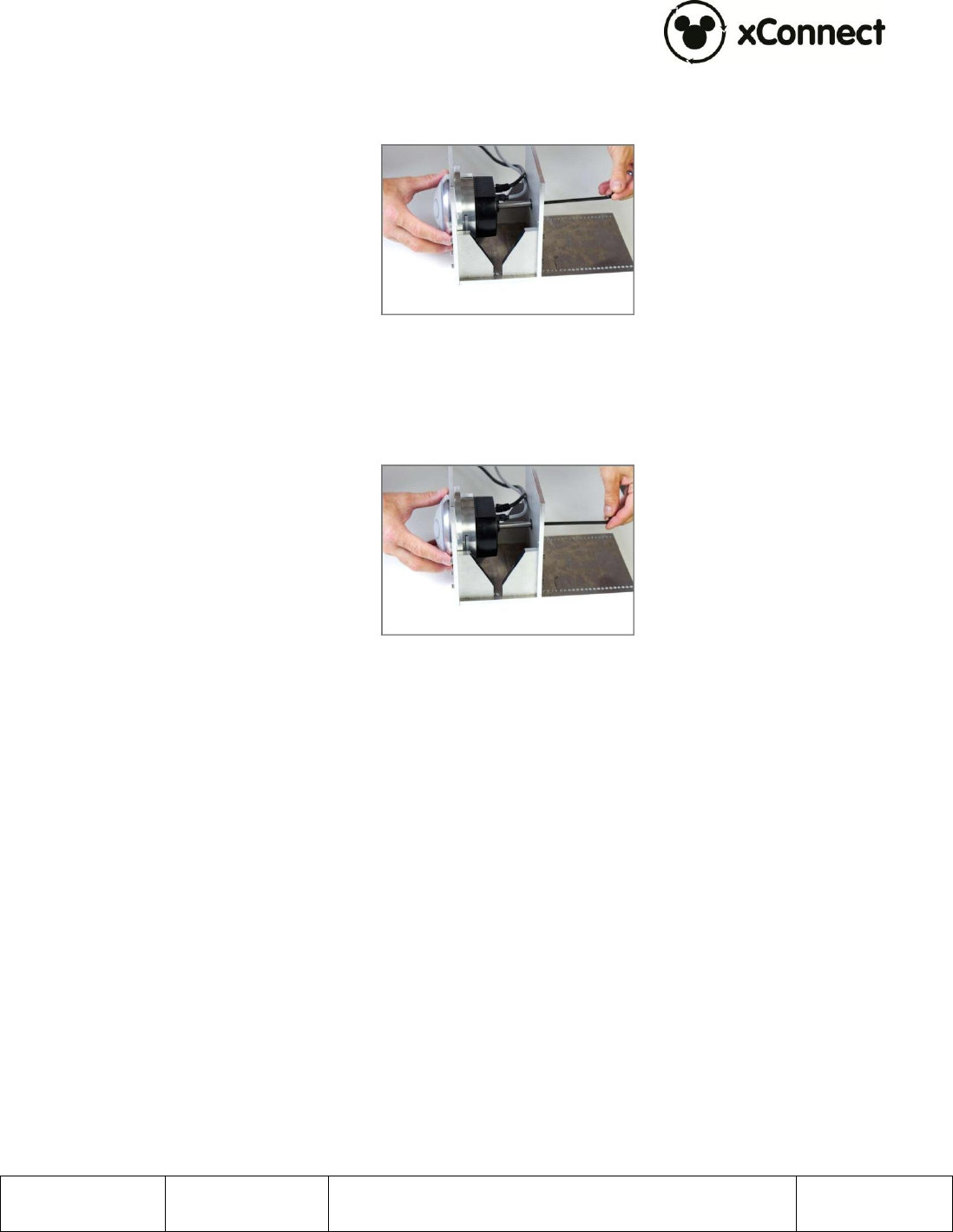
5. Push the xTPA in until you meet some resistance.
Figure 10.9 – Pushing the Subassembly
6. When you meet resistance, the xTPA has contacted the screw at the back of the
stanchion.
Figure 10.10 – Contacting the Screw
900-0142
Rev 01
xTP Installation and User Guide
Page 16 of 16
Confidential and Proprietary
7. Using a 3/16” Hex wrench, turn the screw at the back of the stanchion clockwise
until the Trim Ring flange is flush against the stanchion’s front wall.
Figure 10.11 – Subassembly Against Stanchion Wall
8. Continue to turn the screw until meeting some additional resistance. At this
point, the screw shoulder has bottomed out in the xTPA.
Figure 10.12 – Screw Shoulder Bottoms Out
9. The installation is complete.