Walt Disney Parks and Resorts US XTP-RA-R1G1 xTPra/xTPrs User Manual xBRC User Interface User Guide
Walt Disney Parks and Resorts US., INC. xTPra/xTPrs xBRC User Interface User Guide
User Manual

900-0153
Rev 01
xTPra & xTPrs Installation and User Guide
Page 1 of 17
Confidential and Proprietary
XTPRA & XTPRS INSTALLATION AND
USER GUIDE

900-0153
Rev 01
xTPra & xTPrs Installation and User Guide
Page 2 of 17
Confidential and Proprietary
Revision History
Rev
Date
Author
Description
01
1/10/2013
Brian Piquette
Initial release
Document Approvers & Sign-Off
Date
Approver
Role
Document Accept/Reject
Patrick Stanko
Project Manager
Brian Piquette
Electrical Engineer
Richard Criado
Product Owner

900-0153
Rev 01
xTPra & xTPrs Installation and User Guide
Page 3 of 17
Confidential and Proprietary
Table of Contents
1 Introduction ................................................................................................. 4
1.1 Purpose ................................................................................................. 5
1.2 Definitions.............................................................................................. 5
2 Safety Warnings ........................................................................................... 6
2.1 Important Safety Instructions ..................................................................... 6
2.2 Explosive Safety Warning ........................................................................... 6
2.3 Lightning Warning .................................................................................... 6
3 Regulatory Compliance ................................................................................... 7
3.1 Federal Communications Commission (United States)........................................ 7
3.2 UL Certification........................................................................................ 7
4 Features ..................................................................................................... 8
4.1 Detailed Interface Descriptions .................................................................... 9
4.1.1 Ethernet 10/100 RJ-45 (PoE): ................................................................ 9
4.1.2 RF Antenna Interface ........................................................................... 9
4.1.3 Peripheral Connector ......................................................................... 10
4.1.4 LED Indicators ................................................................................. 10
4.2 RFID Capabilities ................................................................................... 10
4.3 Operating Conditions .............................................................................. 10
4.4 Power ................................................................................................. 11
4.5 Physical ............................................................................................... 12
4.5.1 xTPra, xTPrs .................................................................................... 12
5 Installation ................................................................................................ 13
5.1 Trained Installation and Service Personnel Warning ........................................ 13
5.2 Electrostatic Discharge Warning ................................................................. 13
5.3 Telecom Warning ................................................................................... 13
5.4 Installation Instructions ........................................................................... 14
5.5 xTPrs Wiring ......................................................................................... 15
6 Operation and Configuration .......................................................................... 16
6.1 xTPrs Configuration Options...................................................................... 16
7 Supply Chain Information .............................................................................. 17

900-0153
Rev 01
xTPra & xTPrs Installation and User Guide
Page 4 of 17
Confidential and Proprietary
1 Introduction
The xConnect xTPra Short Range Reader is part of a proprietary data acquisition and
tracking system. It provides an HF RFID reader (TX/RX) to read RFID tag data from
proprietary RFID media. This RFID tag data can be then sent over an Ethernet connection to
a data collection/concentration object. The xTPra is designed to be mounted in harsh
environments.
The xTPrs is a derivative model of the xTPra that adds support for being powered by 24VDC
and interfacing to an external sensor through its peripheral interface connect or.

900-0153
Rev 01
xTPra & xTPrs Installation and User Guide
Page 5 of 17
Confidential and Proprietary
1.1 Purpose
This document provides basic installation and user instructions for the Synapse xTPra
Short Range Reader and the xTPrs Sensor Monitor.
1.2 Definitions
Term
Definition
RFID
Radio Frequency Identification
OTS
Off the shelf
cULus (NRTL)
Canadian & US Underwriters Lab
recognition
(Nationally Recognized Testing Laboratory)

900-0153
Rev 01
xTPra & xTPrs Installation and User Guide
Page 6 of 17
Confidential and Proprietary
2 Safety Warnings
2.1 Important Safety Instructions
When using this device, basic safety precautions should always be followed to reduce
the risk of fire, electric shock and injury to persons.
Do not use this product near water. For example, do not use:
near a bath tub
near a wash bowl
near a kitchen sink or laundry tub
in a wet basement
near a swimming pool
2.2 Explosive Safety Warning
Warning! Do not operate this device near explosive devices, unshielded blasting caps
or in an otherwise explosive environment unless the device has been approved for suc h
use by qualified personnel.
Warning! Do not disconnect the power or any other cabling in an explosive
environment until such qualified personnel, trained specifically in explosive environment
handling, have determined it is safe to do so.
2.3 Lightning Warning
Warning! Do not connect or disconnect cables or otherwise work with the device
hardware during periods of lightning activity.
Avoid using this product during an electrical storm. There may be a remote risk o f
electric shock from lightning.

900-0153
Rev 01
xTPra & xTPrs Installation and User Guide
Page 7 of 17
Confidential and Proprietary
3 Regulatory Compliance
3.1 Federal Communications Commission (United States)
Regulatory Compliance Information
This device complies with part 15 of the FCC Rules. Operation is subject to the following
two conditions: (1) These devices may not cause harmful interference, and (2) these
devices must accept any interference received, including interference that may cause
undesired operation.
Caution:
Any changes or modifications not expressly approved by Walt Disney Parks and Resorts
U.S. (WDPR) could void the user’s authority to operate this equipment. These products
have been certified to be used with the following set of RFID Antennae:
RFID Antenna
Description
Vendor
Part Number
Octogon
Walt Disney Imagineering
WMKPLFMND0201
Circular
Synapse Product Development
600-0286-00
Large Rectangle
Skyetek
18362-900-00003
Small Rectangle
Feig Electronics
1967.00.00
3.2 UL Certification
The xTPra has been certified as a UL Listed Product to the UL 60950-1 standard.
The xTPrs has been certified as a UL Recognized Component to the UL 60950-1
standard.
900-0153
Rev 01
xTPra & xTPrs Installation and User Guide
Page 8 of 17
Confidential and Proprietary
4 Features
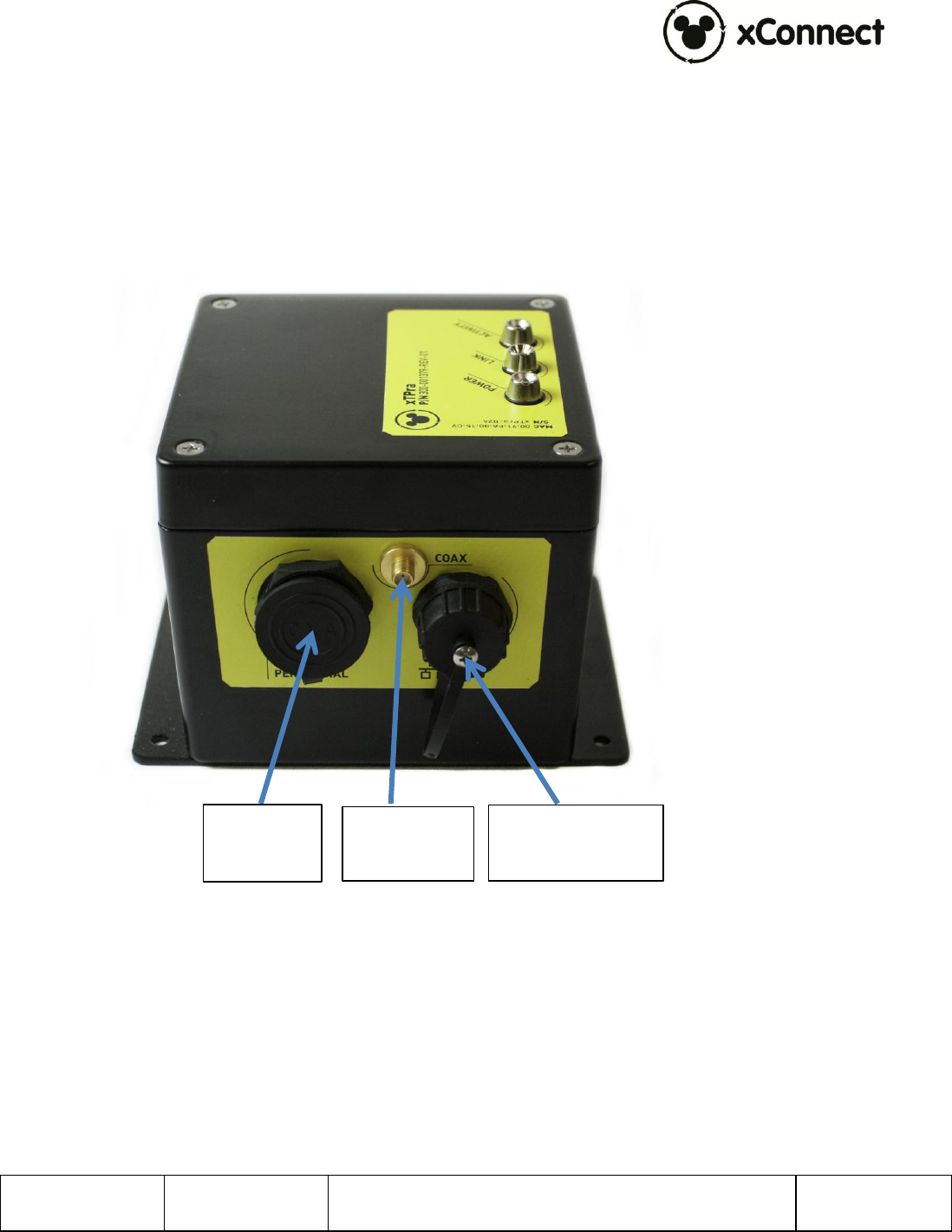
The following two images show the external interfaces to the xTPra/xTPrs. Detailed
descriptions of each follow. The xTPra and xTPrs are identical physically except the xTPrs
has a blue label. The Peripheral Interface on the xTPra is not connected internally.
Figure 1 – xTPra/xTPrs Interfaces, Side View
Ethernet 10/100
RJ-45 (POE)
RF Antenna
Interface
Peripheral
Connector

900-0153
Rev 01
xTPra & xTPrs Installation and User Guide
Page 9 of 17
Confidential and Proprietary
Figure 2 – xTPra/xTPrs Interfaces, Top view
4.1 Detailed Interface Descriptions
4.1.1 Ethernet 10/100 RJ-45 (PoE):
The Ethernet interface is standard 802.3af PoE interface. The external connector is
an IP67 rated connector. This connector is from L-Com, Part number WPRJ-FTCAT5E.
Cable Assemblies in the L-Com TRD5WP and WPRJ series will mate with this
connector of an IP67 rated connection.
With external DC power applied to the xTPrs through the peripheral interface, that
power source will be internally selected over the PoE interface.
4.1.2 RF Antenna Interface
The RF interface provides a 50 SMA connection to an external 13.56MHz antenna.

900-0153
Rev 01
xTPra & xTPrs Installation and User Guide
Page 10 of 17
Confidential and Proprietary
4.1.3 Peripheral Connector
On the xTPrs the peripheral interface connector is available. The Peripheral
Connector on the xTPra model is not connected internally.
The 18 pin Peripheral connector provides the DC input power source for the xTPrs as
well as an opto-coupled input signal.
The pinout of this connector is as follows:
Pin
Function
4
+24VDC Power Input
5
+24VDC Return
10
Optically isolated input,
Current sinking or Current
Sourcing options, 24VDC
max. See “xTPrs
Configuration Options” for
more details.
1-3,6-9, 11-18
All other pins are reserved
for future use. DO NOT
CONNECT.
The part number of the peripheral connector is 14282-18SG-300. This is a
Switchcraft/Conexall part.
Synapse cable Part number 604-0029-00, the xTPrs Sensor Peripheral Cable, can be
ordered and incorporated into an installation for the xTPrs Sensor Input use case.
4.1.4 LED Indicators
There are 3 LED indicators on the top of the xTPra:
o Power: Indicates if the unit is powered by either PoE or the DC input via
the peripheral connector.
o Link, Activity: These two LEDs reflect the state of the Ethernet port.
4.2 RFID Capabilities
TX/RX : 13.56 MHz
ISO 14443A, with support for proprietary security protocols
4.3 Operating Conditions
Temperature:
Operating: -10°C to 50°C

900-0153
Rev 01
xTPra & xTPrs Installation and User Guide
Page 11 of 17
Confidential and Proprietary
Storage: -20°C to 60°C
Operating Relative Humidity: 90% condensing/non-condensing
Altitude: 8,000 ft @28°C (82.4°F)
4.4 Power
The xTPra’s power source is via the PoE capable Ethernet port. This port supports
the IEEE 802.3at-2009 standard.
The xTPra’s rated power consumption is less than 6W.
The xTPrs’ power source is the DC power input through the peripheral connector
interface.
DC Input: 24Vdc, 1A max
NOTE: This product must be used w ith a DC pow er source that is cULus (NRTL) Listed, w ith an
output rated 24VDC +/- 20% maximum, minimum 1A , Marked “LPS” or “Class 2”, output rated
SELV, non-energy hazardous.

900-0153
Rev 01
xTPra & xTPrs Installation and User Guide
Page 12 of 17
Confidential and Proprietary
4.5 Physical
4.5.1 xTPra, xTPrs
xTPra, PN: 300-001379-01
xTPrs, PN: 300-001379-02
Material: Aluminum
Dimensions:
Height: 4.090”
Width: 4.75”
Length: 5.874” (including mounting plate)
Unit Weight: 360 grams
Figure 2 – xTPra Unit

900-0153
Rev 01
xTPra & xTPrs Installation and User Guide
Page 13 of 17
Confidential and Proprietary
5 Installation
5.1 Trained Installation and Service Personnel Warning
Warning! Installation and service of this product is to be performed by trained
installation and service personnel only. Read and follow all warning notices and
instructions marked on the product or included in the documentation. Before installing
the product, read the rest of this document and follow specific product instructions.
When installing, the placement of the device must also satisfy the following installation
requirements:
Placement must allow for easily disconnecting the power cord/adapter of the
device from the AC wall-outlet.
Keep the device away from excessive heat and humidity and keep the devic e
free from vibration and dust.
Installation must at all times conform to local regulations.
Network Connections can be made with either Unshielded Twisted Pair (UTP) or
Shielded Twisted Pair (STP) cabling.
5.2 Electrostatic Discharge Warning
Warning! Wear an anti-static wrist strap or take other suitable measures to prevent
electrostatic discharge when handling this equipment.
5.3 Telecom Warning
Note: This unit is intended for local (intra-building) connections only and is not
designed or evaluated for direct connections to the public telecommunications/cable
distributions systems. Cable and Ethernet connections should be made in accordance to
the National Electrical Code (NEC). For example, one of the following should be true*:
- Cable runs are located in the same building as this unit.
- Cable runs through air between buildings are less than 42m (140ft).
- Cable runs between buildings are directly buried.
- Cable runs between buildings are in underground conduit, where a continuous metallic
cable shield or a continuous metallic conduit containing the cable is bonded to each
building grounding electrode system.
*These options are from the US National Electrical Code, Sections 800.10, 800.12, 800.13, 800.31, 800.32,
800.33, and 800.40.
900-0153
Rev 01
xTPra & xTPrs Installation and User Guide
Page 14 of 17
Confidential and Proprietary
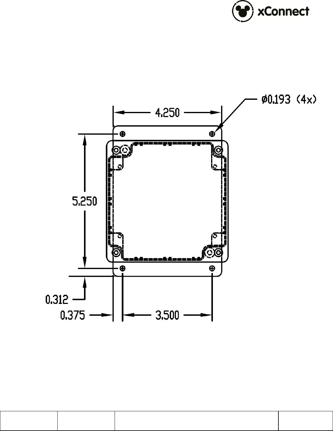
5.4 Installation Instructions
The xTPra/xTPrs can be mounted via the 4 holes in the base plate. The base plate is
0.090” thick. The hole dimensions are shown below.
It is important that this device be mounted in a secure manner. When attaching to a
wall always mount to a wall stud or similar structural component using appropriate
mounting screws.
900-0153
Rev 01
xTPra & xTPrs Installation and User Guide
Page 15 of 17
Confidential and Proprietary
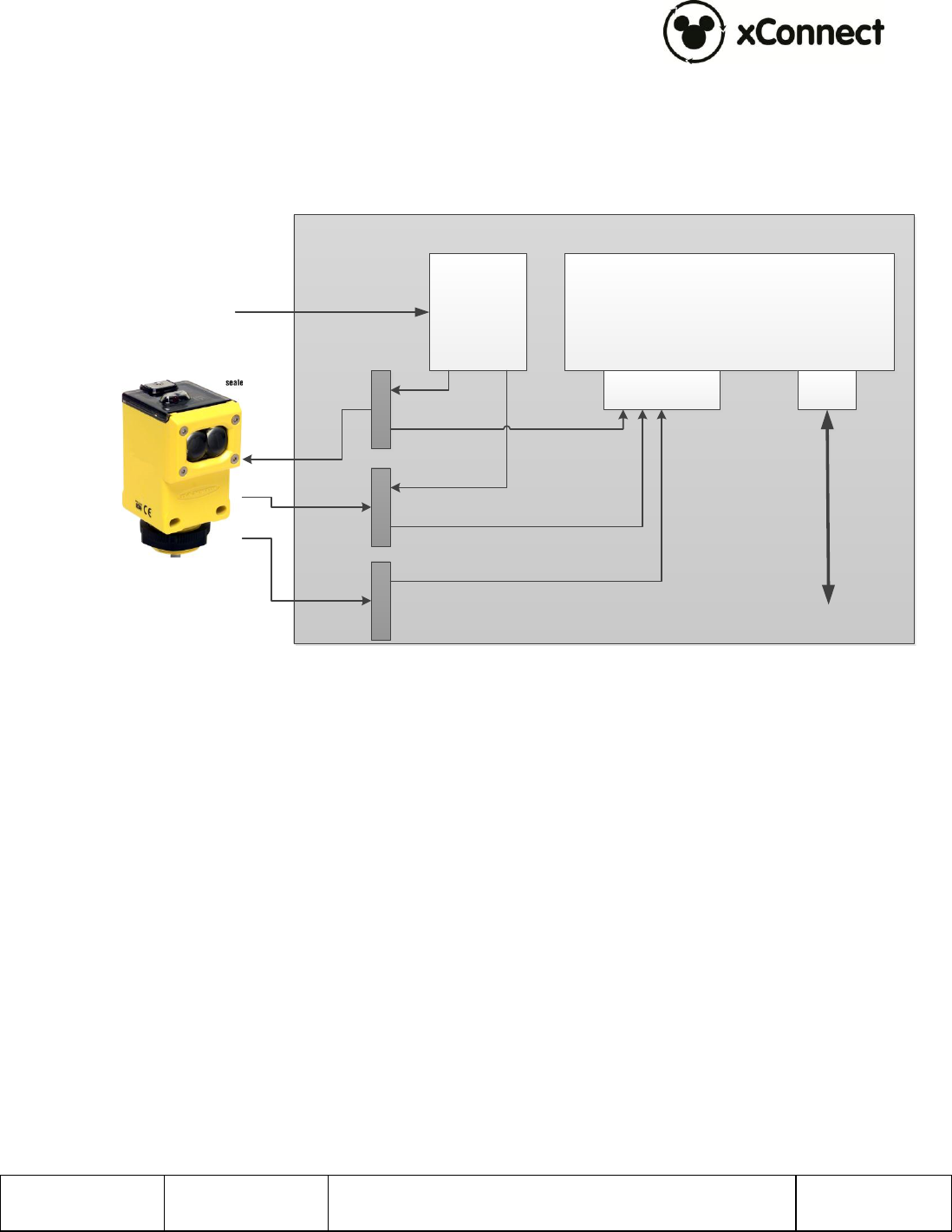
5.5 xTPrs Wiring
The xTPrs is intended to be used with a wide variety of Industry standard discrete
output proximity detectors that provide a Normally Open, PNP or NPN output.
The xTPrs should be connected to the sensor as shown in the diagram below.
xTPrs
RJ45
Peripheral
Connector
24VDC DIN
Rail Supply
+24VDC RTN +24VDCSignal
To Switch
AC
900-0153
Rev 01
xTPra & xTPrs Installation and User Guide
Page 16 of 17
Confidential and Proprietary
6 Operation and Configuration
For more detailed configuration and operational instructions, please refer to document 900-
0060, xBRC User Interface User Guide.
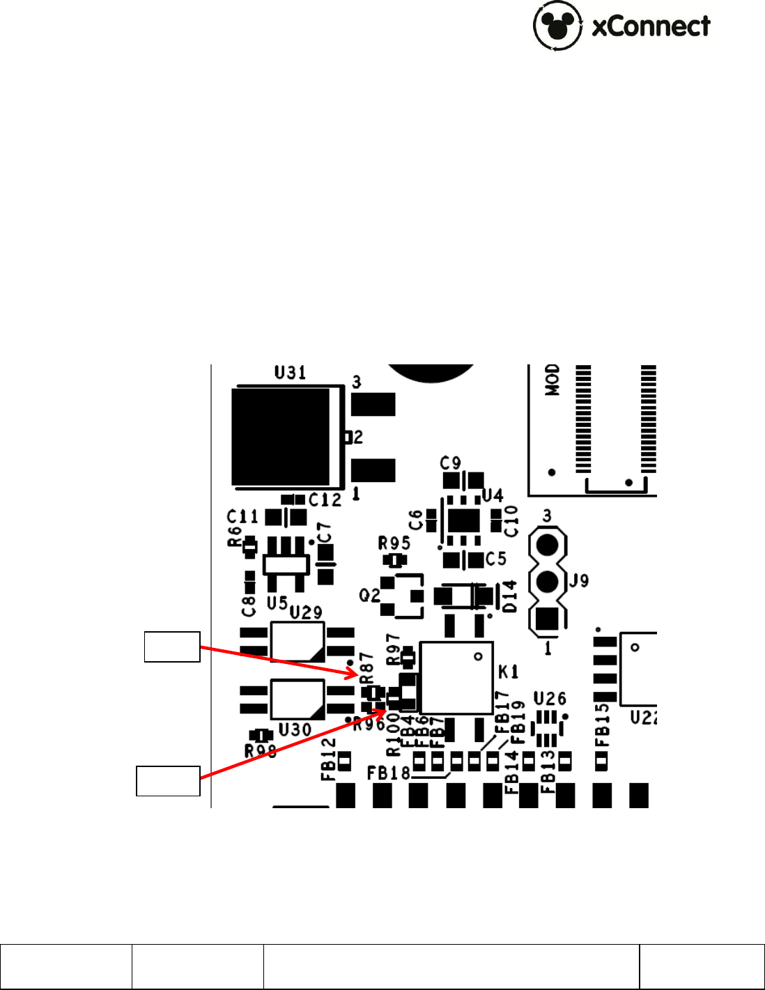
6.1 xTPrs Configuration Options
The default configuration of the xTPrs sensor interface input is current sinking which
supports PNP (current sourcing) type sensors.
This interface can be reconfigured to support NPN (current sinking) type sensors by
modifying a PCB component installation.
To change the configuration to NPN Sensor, remove R100 and install a 0402, zero ohm
resistor at R87.
R87
R100

900-0153
Rev 01
xTPra & xTPrs Installation and User Guide
Page 17 of 17
Confidential and Proprietary
7 Supply Chain Information
This section provides part numbers for xTPra, xTPrs and related components created by
Synapse:
Component
Features and Part Numbers
Vendor
xTPra: 300-001379-01
xTPrs: 300-001379-02
Synapse
Octogon RFID
Antenna
WMKPLFMND0201
Walt Disney
Imagineering
Circular RFID
Antenna
600-0286-00
Synapse Product
Development
Large Rectangle
RFID Reader
18362-900-00003
Skyetek
Small Rectangle
RFID Reader
1967.00.00
Feig Electronics
xTPra Sensor
Peripheral Cable
604-0029-00
Synapse