Wanlida Group CF-8003 Wireless Reversing Camera User Manual Camera 080703
Wanlida Group Co., Ltd. Wireless Reversing Camera Camera 080703
User Manual
1
Your GPS device comes with a wireless reversing Camera. When the rear gear is
engaged, the image from the camera will be displayed on the screen of your GPS device,
aiding you in parking in difficult spots (works if camera is linked to the reversing light).
Included with the reversing camera are the following fitting parts; License Plate Bolts,
Wedge shaped mounting shims. These parts should be sufficient to mount the camera to
most vehicles. However, some vehicles may require additional parts for fitment.
WARNING: This device, as well as all other wireless devices, may be subject to
interference. Interference may be caused by cell phones, Bluetooth headsets, Wi-FI
routers, power lines and other various electrical equipment, etc. Also note that holding
the GPS unit in your hands may also result in interference.
Camera Installation
You may mount the camera using the license plate’s top or bottom mounting bolts or
screws. When mounting the camera you must make sure that it’s field of view is not
obstructed. Depending on the vehicle, you may mount the camera on the top or bottom
of the license plate. You can use the wedge shaped shims to alter the angle of the
camera during fitting, so that the best view is achieved.
1. Loosen the license plate bolts/screws, then remove the rear license plate.
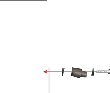
2. Insert each license plate bolt into a supplied wedge, then through the bolt holes of
the camera, then through the remaining wedges and the license plate. (Fig.1)
3. Align with holes on vehicle and temporarily tighten the license plate bolts. The
wedges will angle the camera down.
4. You will need to choose a route for the camera’s power cable through the vehicle’s
body to the reverse light circuit.
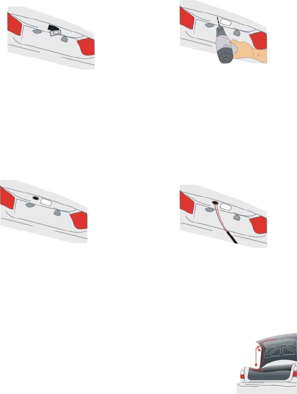
5. Some vehicle’s may have a hole available to pass the wire through, you can use an
existing opening (Fig.2) like where a license plate light is mounted, or drill a hole
close to where the power cable is attached to the camera. (Fig.3) Once you have
chosen where the cable will enter the vehicle’s body, remove the camera. If you
able to use an existing opening, skip the next two steps.
Fig 1
License Plate W
edge
Ca
m
e
r
a
W
edge
Sc
r
e
w
2
6. If you are going to drill a hole, choose a location as close to the camera where the
power cable comes out of it. Before You Drill A Hole You Must Check And See
What Is Behind Where You Are Drilling. If there are any vehicles components,
such as electrical parts or fuel system components behind where you are drilling,
you must take whatever precaution is necessary not to damage them. Remove the
license plate and camera before drilling.
7. After you have drilled a hole, pass the power cable through the wedge into the
vehicle.
8. Next you’ll need to find the vehicle’s reverse lights. Turn the vehicle’s ignition key to
the accessory position, engage the parking brake and put the car in reverse. Look
at the vehicle’s tail lights to see where the reverse lights are located.
To locate the reverse light’s 12V+ wire it will be necessary to gain access to the rear
of the vehicle’s tail light.
For help locating the vehicle’s reverse light circuit contact your vehicle’s
manufacturer for vehicle specific wiring diagrams.
9. Once you have located the reverse light circuit you will have to
route the camera’s power cable to that location. You must
securely fasten the power cable to prevent it from being caught
on any vehicle component such as the trunk hinge (Fig.6).
Never route the cable on the outside of the vehicle.
10. The sockets for most vehicle’s reverse lights have two wires
connected to them. One is positive and one is negative, to determine which is
positive you will need at least a 12V test light available at any auto parts store, or a
multi-meter. Using the test light, attach the negative lead to a spot on the vehicle
that has a chassis ground, with the reverse light on touch the other lead to one of
the wires on the reverse light socket. When you touch one of the wires and the test
light comes on that wire is the positive wire, if the test light doesn’t come on, that
Fig 2 Fig 3
Fig 6
3
wire is the negative wire.
11. After determining which wire is the positive and which is the negative, turn off the
ignition key, then remove the battery’s negative cable.
12. Wire the camera directly to the reverse light circuit by stripping the reverse light
wires then twisting the camera wires to the exposed reverse light wires (ideally
these should then be soldered to form a secure connection). Once connected, wrap
with electrical tape. Do not attempt this if you are not knowledgeable with electrical
installation practices.
13. Next splice the black wire of the camera’s power cable to the reverse light’s
negative (-) wire or ground.
14. Replace the reverse light bulb, then re-install the light socket. Secure all the wires
with cable ties or electrical tape. Re-attach the negative battery cable to the battery.
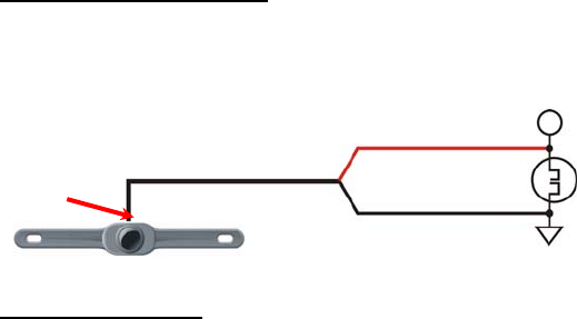
CAMERA Wiring Diagram
The camera is equipped with Reverse Voltage Protection. If the camera does not operate,
please check that the Red wire is connected to positive (+) and the Black wire is
connected to negative (-).
Testing the System
1. Reattach the vehicle’s negative battery cable.
2. Engage the parking brake and turn the ignition key to the ON position. DO NOT
start the vehicle. Put the gear shift into reverse.
3. The camera will start broadcasting, and the GPS unit screen will detect the signal
and enter the Back-up camera mode automatically. The image will be displayed on
the screen and it should match roughly what you see in your rear view mirror. It
might be lower and at a different angle.
4. When you take the gear shift out of reverse the camera will turn OFF, and the GPS
unit screen will turn back.
After testing the unit and you are satisfied with the route you have chosen for the cabling,
you must permanently install it.
RED
BLACK
+12V DC REV LAMP
Reverse Lamp
GRUND
The camera’s antenna extends
down the camera’s cable. Do not
cut the camera’s cable shorter
than 41cm or 12”.

4
Fully tighten the license plate bolts.
Route all wires behind interior panels or under carpeting so they are hidden.
Use cable ties to neatly gather all excess wire.
Note: Keep camera lens and the GPS unit screen clean to ensure optimum picture
quality.
Camera Operation
Once fully fitted into the vehicle the operation of the reversing camera is simple.
Whenever you put the vehicle into reverse, the camera picture will automatically appear
on the GPS unit display.
The optimal viewing angle of this camera is 120 degree horizontally and 140 degree
diagonally. The optimal viewing distance is about 2M.
NOTE: the Camera receiver needs to be fitted to the GPS unit for the camera to work.
(See GPS instruction manual)
Changes or modifications not expressly approved by the party responsible for
compliance could void the user's authority to operate the equipment. This device complies
with Part 15 of the FCC Rules. Operation is subject to the following two conditions:
(1) this device may not cause harmful interference, and
(2) this device must accept any interference received, including interference that
may cause undesired operation.
FCC Radiation Exposure Statement The antennas used for this transmitter must be
installed to provide a separation distance of at least 20 cm from all persons and must not
be collocated or operating in conjunction with any other antenna or transmitter.