Wanlida Group PG74303GCMC Wireless Reversing Camera User Manual PG 74303 071011
Wanlida Group Co., Ltd. Wireless Reversing Camera PG 74303 071011
Users Manual
1
,
POWER SUPPLY:
Connect the supplied adapter to the side of the unit in the slot marked “DC 5V IN”. Plug
the two-prong end of the power cord into an AC outlet or the cigarette lighter socket of
the vehicle. If you have difficulty inserting the plug, turn it over and reinsert it. If the unit
will not be used for a long time, disconnect the plug from the socket.
NOTE:
Before plugging the power cord into an AC outlet or a cigarette lighter socket of vehicle,
make sure that all the connections have been made.
CAUTION: These servicing instructions are for use by qualified service personnel only.
To reduce the risk of electric shock, do not perform any servicing other than that
contained in the operating instructions unless you are qualified to do so.
Refer to service manual for servicing instructions. To reduce the risk of fire or electric
shock, do not expose this apparatus to rain or moisture.
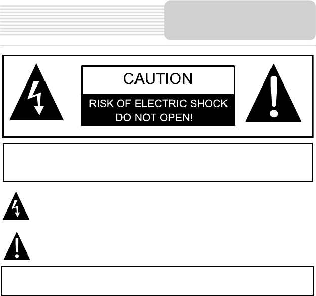
CAUTION: TO REDUCE THE RISK OF ELECTRIC SHOCK, DO NOT
REMOVE COVER (OR BACK). NO USE-SERVICEABLE PARTS
INSIDE. REFER SERVICING TO QUALIFIED SERVICE PERSONNEL.
The lightning flash with arrowhead symbol, within an equilateral triangle, is
intended to alert the user to the presence of uninsulated “dangerous voltage”
within the product’s enclosure that may be of sufficient magnitude to
constitute a risk of electric to persons.
The exclamation point within an equilateral triangle is intended to alert the
user to the presence of important operating and maintenance (servicing)
instructions in the literature accompanying the appliance.
WARNING: TO REDUCE THE RISK OF FIRE OR ELECTRIC SHOCK,
DO NOT EXPOSE THIS APPLIANCE TO RAIN OF MOISTURE.
Important
S
a
f
ety
Instructions

2
NOTES
1) Read these instructions.
2) Keep these instructions.
3) Heed all warnings.
4) Follow all instructions.
5) Do not use this apparatus near water.
6) Clean only with a damp cloth.
7) Do not block any of the ventilation openings. Install in accordance with the
manufacturer's instructions.
8) Do not install near any heat sources such as radiators, heat registers, stoves, or
other apparatus (including amplifiers) that produce heat.
9) Do not defeat the safety purpose of the polarized or grounding-type plug. A
polarized plug has two blades with one wider than the other. A grounding type plug
has two blades and a third grounding prong. The wide blade or the third prong is
provided for your safety. When the provided plug does not fit into your outlet,
consult an electrician for replacement of the obsolete outlet.
10) Protect the power cord from being walked on or pinched particularly at plugs,
convenience receptacles, and the point where they exit from the apparatus.
11) Only use attachments/accessories specified by the manufacturer.
12) Use only with a cart, stand, tripod, bracket, or table specified by the
manufacturer, or sold with the apparatus. When a cart is used, use
caution when moving the cart/apparatus combination to avoid injury from tip-over.
13) Unplug this apparatus during lightning storms or when unused for long periods of
time.
14) Refer all servicing to qualified service personnel. Servicing is required when the
apparatus has been damaged in any way, such as power-supply cord or plug is
damaged, liquid has been spilled or objects have fallen into the apparatus, the
apparatus has been exposed to rain or moisture, does not operate normally, or has
been dropped.
15) Apparatus shall not be exposed to dripping or splashing and no objects filled with
liquids, such as vases, shall be placed on the apparatus.
Important
S
a
f
ety
Instructions

3
Warning
Failure to avoid the following potentially hazardous situations may result in injury or
property damage.
The unit is designed to provide you with route suggestions. It does not reflect road
closures or road conditions, traffic congestion, weather conditions, or other factors that
may affect safety or timing while driving.
Use the unit only as a navigational aid. Do not attempt to use the unit for any purpose
requiring precise measurement of direction, distance, location, or topography. This
product should not be used to determine ground proximity for aircraft navigation.
CAUTION:
Danger of explosion if battery is incorrectly replaced. Replace only with the same or
equivalent type.
The batteries (or batteries installed) shall not be exposed to excessive heat such as
sunshine, fire or the like.
Underwriters Laboratories Inc. (“UL”) has not tested the performance or reliability of the
Global Positioning System (“GPS”) hardware, operating software or other aspects of this
product. UL has only tested for fire, shock or casualty hazards as outlined in UL’s
Standard(s) for Safety [Note-Consider referencing specific UL standard].
UL Certification does not cover the performance or reliability of the GPS hardware and
GPS operating software.
UL MAKES NO REPRESENTATIONS, WARRANTIES OR CERTIFICATIONS
WHATSOEVER REGARDING THE PERFORMANCE OR RELIABILITY OF ANY GPS
RELATED FUNCTIONS OF THIS PRODUCT.
This device complies with part 15 of the FCC Rules. Operation is subject to the following
two conditions:
(1) This device may not cause harmful interference, and
(2) This device must accept any interference received, including interference that may
cause undesired operation.
Changes or modifications not expressly approved by the party
responsible for compliance could void the user's authority to operate the
Important
S
a
f
ety
Instructions
4
equipment.
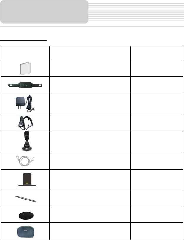
Accessories List
ITEM NAME QTY
Owner’s Manual 2
Back-up Camera 1
AC Adaptor 1
Car Adaptor 1
Mounting Bracket 1
USB Cable 1
Mounting cradle 1
Touch Pen 1
Dashboard mount disk 1
Pouch 1
NOTE
Accessories and their parts numbers are subject to modification without prior notice due
Accessories

5
to improvements.
…………………………………….………..1
……………………………….………..…...4
……………………………….………….....6
……………………………….……….…....8
…………………………….……….….….10
……………………………….……………12
…………………………….………………16
……………………………….……………18
……………………………….…………...20
……………………………….…………...21
……………………………….…………...26
………………………………………….…28
Important Safety Instructions
System Connections
Power Supply Preparation
Troubleshooting
Specifications
Accessories
View of Main Unit
GPS Unit Installation
Contents
Playing Music
Photo Viewer
General Setup
Back-up Camera Installation
6
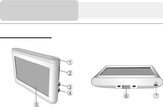
Front and Side panel
1. POWER button
Press the power button for longer time to enter or exit the standby mode.
2. Card Port
Insert the SD card into the port.
3. Headphone Jack
Used to connect headphones for private listening. When the headphones are
connected to this jack, the speaker will be turned off automatically.
4. DC 5V Input Jack
Used to connect to the supplied adapter.
5. LCD Screen
6. Grooves
Used to connect the receiver located in the mount cradle for back-up camera signal
input.
7. USB Port
Used to connect to the USB device.
View of Main Unit
7
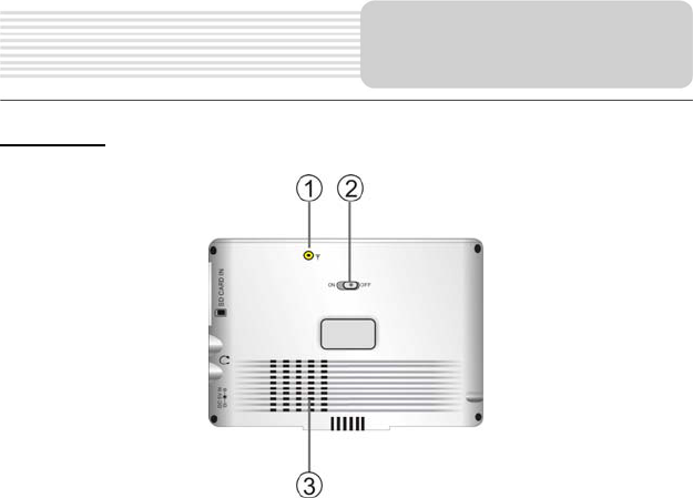
Rear View
1. External GPS Antenna Jack
Connected to the external antenna (optional).
2. ON/OFF Switch
Used to switch power on or off.
3. Speaker
View of Main Unit
8
z Always ensure that the unit and any other external device connected to the unit are
switched off and unplugged from the power supply before you attempt to connect
the unit to any external device.
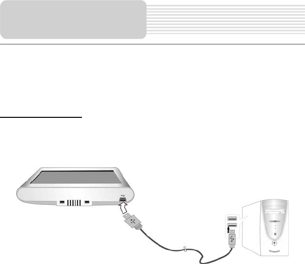
Connecting to PC
The unit is designed with a USB port which allows you to connect the unit to PC for map
updating. See the below figure for details:
System requirements:
-Windows 98SE, ME, 2000 and XP
(Driver required for Windows 98SE)
-DVD Rom Drive (for map upgrade purposes)
-Intel Pentium II 233 Mhz
-64 MB RAM
-50 MB available hard drive space
-Available serial port and/or USB Port
-256-color display adapter and monitor
(16 bit color required)
In the near future map updates will be available for down load from our website. Please
check www.nextar.com periodically for the information on downloads.
System
Connections
9
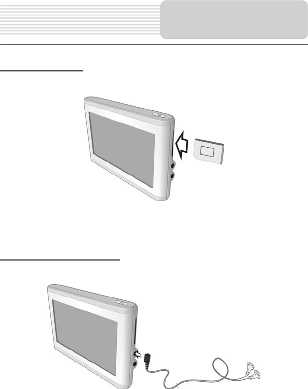
Inserting SD Card
The unit is designed with SD Card jack which allows you to insert the SD card into the
unit as shown below:
To remove the card, gently press the card in with your fingernail. The card unlocks and
protrudes slightly. Then remove the card
Connecting to Earphones
Connect the earphones to the right side of the unit for private listening.
When earphone is connected, the speakers will automatically turn off.
Note: Excessively loud volume could damage your hearing. So turn down the volume
before you connect the earphones, and then raise the volume to comfortable level.
System
Connections
10
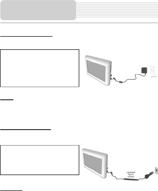
Using the AC Adaptor
The unit is supplied with an AC adaptor for powering it and charging its battery.
Note:
¾ Turn unit's power off before unplugging.
¾ In the case of using the adaptor, the LCD screen will be brighter than with the
rechargeable battery.
Using of Car Adaptor
The unit is supplied with a Car Adaptor for powering it while in a vehicle.
Attention
¾ Place the unit in a proper position for viewing.
¾ Disconnect the unit from the Car Adaptor when starting the vehicle.
Your portable GPS unit comes with a built-in rechargeable battery. Please see details in
the following segment.
Power Supply
Pre
p
aration
Connect the Car Adaptor Power Plug to
the unit’s power jack and plug the other
end to the vehicle’s 5V accessory/
cigarette socket, as shown on the right
figure.
1. Connect AC adaptor to the right
side of the unit in the jack marked
DC 5V IN, as shown on the right.
2. Plug the two-prong end of the
power cord into a grounded
electrical outlet.

11
Working conditions and precautions for the rechargeable battery
¾ Battery should only be used and charged when temperatures are between
32°-100°F.
¾ Maintain well-ventilated conditions around the product to avoid overheating. Don’t
put the product on a bed, sofa or anything that may block ventilation to the product.
¾ When the battery is weak, an indication menu will appear on the LCD screen and
about five minutes later, the player will power OFF automatically.
Charging the Battery Pack
The battery must be charged by using the supplied adaptors.
Power Supply
Pre
p
aration
12
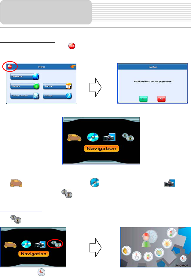
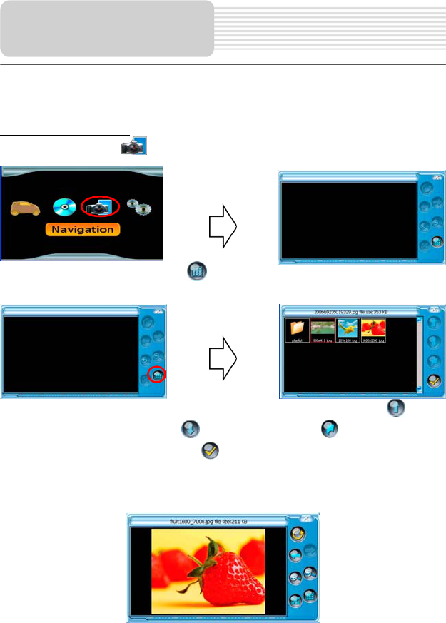
System Main Menu
When in navigation mode, tap button in the Menu screen. A confirmation message
appears asking if you want to exit the program now, as shown below.
In the confirmation screen, tap Yes and the system main menu appears.
In the main menu, there are four items for selecting. Touch the corresponding item to
enter.
Tap to enter navigation mode; tap to enter the MP3 player; tap to
enter the Photo Viewer; tap to enter the settings menu.
Settings Menu
Tap to enter the settings menu, the screen will display as below:
In the menu, tap to return to the main menu.
General Setup
13
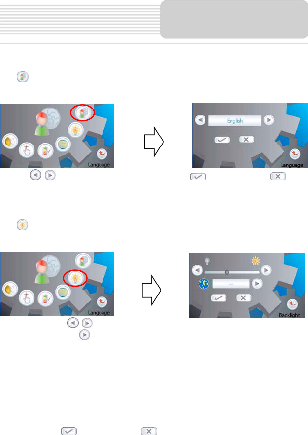
Language
Tap in the settings menu to enter Language settings menu for language selecting,
as shown below:
Tap the buttons to select language. Then tap to confirm or tap to
cancel.
Backlight
Tap in the settings menu to enter Backlight settings menu for backlight adjusting,
as shown below:
Tap the first group buttons to adjust the backlight level.
Tap the second group buttons to adjust the sleep time. There are 6 choices for sleep
time (--/5/10/30/60/120).
--: The system will keep backlight always on and will not enter sleep mode.
5: The system will keep backlight on for 5 minutes and then enter sleep mode.
10: The system will keep backlight on for 10 minutes and then enter sleep mode.
30: The system will keep backlight on for 30 minutes and then enter sleep mode.
60: The system will keep backlight on for 1 hour and then enter sleep mode.
120: The system will keep backlight on for 2 hours and then enter sleep mode.
After setting, tap to confirm or tap to cancel.
General Setup
14
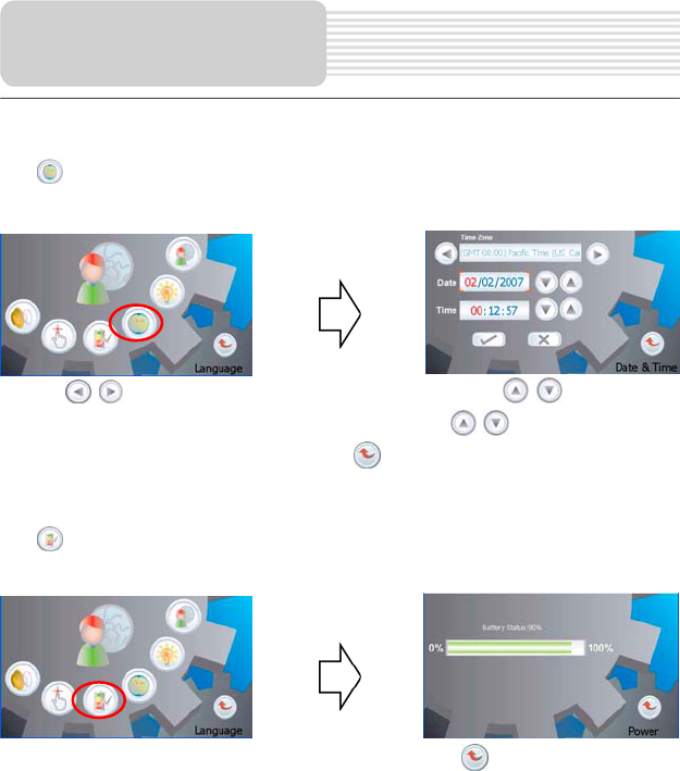
Date & Time
Tap in the settings menu to enter Date & Time settings menu for changing to the
current time zone, as shown below:
Tap the buttons to select the proper Time Zone. Tap the buttons of
Date group to change the corresponding date and tap the buttons of Time
group to change the corresponding time. Tap to return.
Power
Tap in the settings menu to enter Power menu for the current battery status, as
shown below:
The power menu will display the current battery status. Tap to return.
General Setup
15
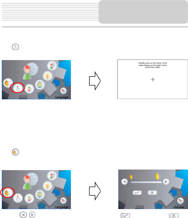
Screen
Tap in the settings menu, the screen will display as below:
This item is used to calibrate the sensitivity of the touch screen. Tap the center of “+” as it
moves around the screen. If you touch the center of “+” every time, it will disappear after
having moved through a cycle (center→top left corner→bottom left corner→bottom right
corner→top right corner). Tap the screen to return to the settings menu.
Note: If “+” doesn’t disappear, you should calibrate again.
Volume
Tap in the settings menu to enter Volume settings menu for volume adjusting, as
shown below:
Tap the buttons to adjust the volume. Then tap to confirm or tap to
cancel.
General Setup

16
The unit is designed with SD card slot. You can insert the SD card with MP3, WMA and
JPEG files. It supports MP3, WMA and JPEG format files playback.
Note: Do not store MP3, WWA and JPEG format files in the Flash storage, for the
flash storage is used to store map data, any attempt to open the Flash storage
may result in the map data missing and lost.
Warning: For your own safety, do not use the earphones when driving.
Take the following steps to play:
Loading MP3, WMA and JPEG format files:
1. Insert the SD card with MP3, WMA and JPEG format files.
2. Turn on the unit.
Playing Music.
In the main menu, tap to enter the playback menu, as shown below:
In the menu, tap the MENU button to enter the MP3 play list menu, as shown below:
Playing Music
17
When you open the play list, the system will look for MP3 files on its SD memory card
and create a play list automatically. If the play list consists of more than one screen, tap
the up arrow for the previous page and the down arrow for the next page.
In the play list, double tap the songs to start playback.
Tap ; when the button changes to orange, the player will repeat all the songs in the
play list.
Tap ; when the button changes to orange, the player will play the songs in the list
randomly.
Tap to return to the MP3 main screen.
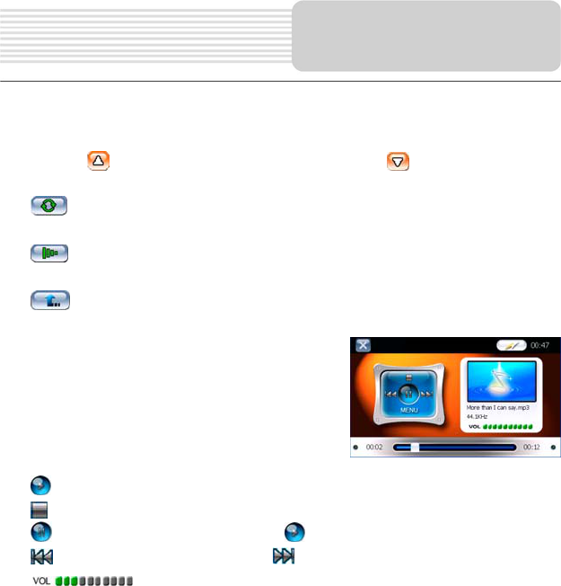
On the playback screen as shown right, the MP3
player has standard playback features:
Tap button to start playing the songs in the play list.
Tap to stop the playback.
Tap to pause the playback, and then tap to resume the playback.
Tap to back to the previous song; tap to skip to the next song.
Use to adjust the volume of the speaker.
Playing Music
18
It lags when reading high-resolution JPEG files in SD Card. We suggest
low-resolution (within 640*480) pictures playback.
Playing JPEG Files
On the main menu, tap to enter the photo viewer main screen, as shown below:
In the Photo Viewer main menu, tap , the pictures stored in the memory card will be
listed on the screen, as shown below:
If the pictures list consists of more than one screen, tap the up arrow for the
previous page and the down arrow for the next page. Tap to return to previous
menu. Tap a picture to select it and tap to confirm your selection.
In the pictures list, double tap a picture to play it on screen, as shown below.
On the playback screen, the Photo Viewer has following playback features:
Photo Viewer

19
Tap to rotate the picture.
Tap to back to previous picture; tap to switch to next picture.
Tap , to zoom the picture in or out.
Tap to play the picture in full-screen mode; double tap the screen again to return to
the Viewer main screen.
Tap to return to the pictures list.
Photo Viewer
20
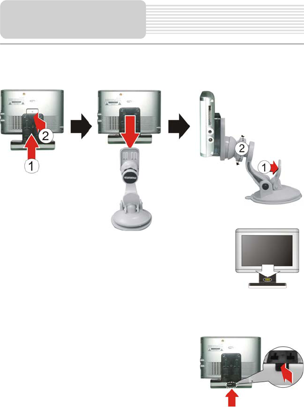
Take the following steps to mount the unit in the vehicle using the supplied mount
accessories (mount bracket, mount cradle, etc.):
1. See Fig. 1. Fix the unit on mount cradle.
There is one wireless receiver in the mount cradle. It can
receive the signal sent by the emitter in the Back-up
Camera and input these signals into the GPS unit by the
combination of the unit and the cradle (see right figure).
2. See Fig. 2. Push the mount cradle and the unit to mount bracket.
3. See Fig. 3. Lift the suction fastener, and place the unit on the desired location, then
press down fastener for immobility. Rotate the knob to adjust the unit to proper
position.
4. If you want to remove the unit, press the tab at
the bottom of the mounting cradle (see right
figure).
Warning:
The device must not be mounted so that it impairs the driver’s view of the road. Please
take extra precaution to ensure the airbags are not obstructed by the device.
GPS Unit
Installation
Fig 1 Fig 2 Fig 3

21
Back-up Camera System Parts
1. Back Up Camera with Video Cable
2. License Plate Bolts
3. Wedge Shaped Mounting Shims
Note: The parts and supplies included with the camera are sufficient for most
installations. However some installations may require other parts and/or supplies to be
purchase separately.
WARNING: This device, as well as all other wireless devices, may be subject to
interference. Interference may be caused by cell phones, Bluetooth headsets, Wi-FI
routers, power lines and other various electrical equipment, etc. And you could not hold
the GPS unit and mount cradle in your hands because this may results in interference
too.
Camera Installation
You may mount the camera using the license plate’s top or bottom mounting bolts or
screws. When mounting the camera you must make sure that it’s field of view is not
obstructed. Depending on the vehicle, you may mount the camera on the top or bottom
of the license plate. To adjust the angle that the camera is mounted to the vehicle use the
supplied wedge shaped shims.
1. Loosen the license plate bolts/screws, then remove the rear license plate.
2. Insert each license plate bolt into a supplied
wedge, then through the bolt holes of the
camera, then through the remaining wedges
and the license plate. (Fig.1)
3. Align with holes on vehicle and temporarily tighten the license plate bolts/screws.
The wedges will angle the camera down.
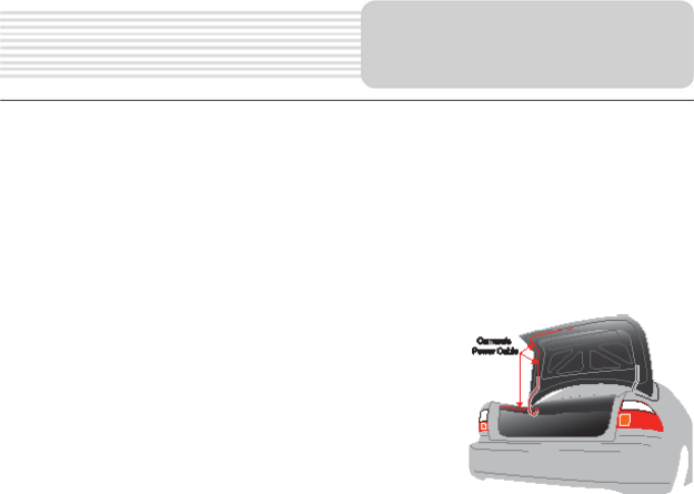
4. You will need to choose a route for the camera’s power cable through the vehicle’s
body to the reverse light circuit.
Fig 1
Back-up Camera
Installation
License Plate W
edge
Ca
m
e
r
a
W
edge
Sc
r
e
w

22
5. Some vehicle’s may have a hole available to pass the wire through, you can use an
existing opening (Fig.2) like where a license plate light is mounted, or drill a hole
close to where the power cable is attached to the camera. (Fig.3) Once you have
chosen where the cable will enter the vehicle’s body, remove the camera. If you
able to use an existing opening, skip the next two steps.
6. If you are going to drill a hole, choose a location as close to the camera where the
power cable comes out of it. BEFORE YOU DRILL A HOLE YOU MUST CHECK
AND SEE WHAT IS BEHIND WHERE YOU ARE DRILLING. If there are any
vehicles components, such as electrical parts or fuel system components behind
where you are drilling, you must take whatever precaution is necessary not to
damage them. Remove the license plate and camera before drilling.
7. After you have drilled a hole, insert the supplied wedge (Fig.4), and then pass the
power cable through the wedge into the vehicle (Fig.5). You must use the wedge to
prevent the metal edge of the hole from cutting the power cable.
Back-up Camera
Installation
Fig 2 Fig 3
Fig 4 Fig 5
23
8. Next you’ll need to find the vehicle’s reverse lights. Turn the vehicle’s ignition key to
the accessory position, engage the parking brake and put the car in reverse. Look
at the vehicle’s tail lights to see where the reverse lights are located.
To locate the reverse light’s 12V+ wire it will be necessary to gain access to the rear
of the vehicle’s tail light.
For help locating the vehicle’s reverse light circuit contact your vehicle’s
manufacturer for vehicle specific wiring diagrams.
9. Once you have located the reverse light circuit you
will have to route the camera’s power cable to that
location. You must securely fasten the power cable
to prevent it from being caught on any vehicle
component such as the trunk hinge (Fig.6). Never
route the cable on the outside of the vehicle.
10. The sockets for most vehicle’s reverse lights have two wires connected to them.
One is positive and one is negative, to determine which is positive you will need at
least a 12V test light available at any auto parts store, or a multi-meter. Using the
test light, attach the negative lead to a spot on the vehicle that has a chassis ground,
with the reverse light on touch the other lead to one of the wires on the reverse light
socket. When you touch one of the wires and the test light comes on that wire is the
positive wire, if the test light doesn’t come on, that wire is the negative wire.
11. After determining which wire is the positive and which is the negative, turn off the
ignition key, then remove the battery’s negative cable.
12. Following the Scotch- LokTM instructions, splice the Red wire using the in-line
Scotch-LokTM wire connectors to the reverse light’s positive (+) wire. Use a set of
slip joint pliers to squeeze the TAP and insure good connection.
13. Next splice the black wire of the camera’s power cable to the reverse light’s
negative (-) wire or ground.
14. Replace the reverse light bulb, then re-install the light socket. Secure all the wires
with cable ties or electrical tape. Re-attach the negative battery cable to the battery.
Back-up Camera
Installation
Fig 6
24
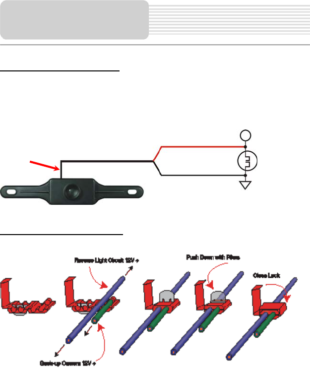
CAMERA Wiring Diagram
The camera is equipped with Reverse Voltage Protection. If the camera does not operate,
please check that the Red wire is connected to positive (+) and the Black wire is
connected to negative (-).
Scotch-LokTM Instructions
You do not need to use the Scotch- LokTM connectors. The camera can be wired directly
to the reverse light circuit by stripping the reverse light wires then twisting the camera
wires to the exposed reverse light wires. Once connected, wrap with electrical tape. Do
not attempt this if you are not knowledgeable with electrical installation practices.
Back-up Camera
Installation
RED
BLACK
+12V DC REV LAMP
Reverse Lamp
GRUND
The camera’s antenna extends
down the camera’s cable. Do not
cut the camera’s cable shorter
than 41cm or 12”.

25
Testing the System
1. Reattach the vehicle’s negative battery cable.
2. Engage the parking brake and turn the ignition key to the ON position. DO NOT
start the vehicle. Put the gear shift into reverse.
3. The camera will start broadcasting, and the GPS unit screen will detect the signal
and enter the Back-up camera mode automatically. The image will be displayed on
the screen and it should match your rear view mirror.
4. When you take the gear shift out of reverse the camera will turn OFF, and the GPS
unit screen will turn back.
After testing the unit and you are satisfied with the route you have chosen for the cabling,
you must permanently install it.
Fully tighten the license plate bolts.
Route all wires behind interior panels or under carpeting so they are hidden.
Use supplied cable ties to neatly gather all excess wire.
Note: Keep camera lens and the GPS unit screen clean to ensure optimum picture
quality.
Operation of the Back-up Camera System
After previous procedure, you can use the Back-up Camera System now.
When driving, put the gear shift into reverse, the GPS unit will detect the signal and
display the image on screen automatically, as shown below.
Note: Keep camera lens and GPS screen clean to ensure optimum picture quality.
Back-up Camera
Installation
26
Take steps described in the tables below to solve simple problems before contacting
customer service.
If you suspect something wrong with the unit, immediately turn the power off and
disconnect the power connector from the unit. Never try to repair the unit yourself
because it is dangerous to do so.
PROBLEM POSSIBLE CAUSE POSSIBLE SOLUTION
There is no
sound. The volume may be turned
down or mute.
Turn up the volume or turn
on the sound output.
Users can’t turn
on the unit.
The adaptor doesn’t connect
well.
Connect the adaptor
correctly.
The built-in rechargeable
battery is weak.
Use the adaptor to supply
power or charge the
battery.
There is too much
dark in the picture. The brightness may be
turned down.
Adjust the brightness of the
LCD.
The unit can’t
receive satellite
signals or can’t
orient.
The unit may be obstructed
by buildings or metal block.
Make sure to use the unit
out of room; if in the
vehicle, you can use the
external GPS antenna to
solve this problem.
Troubleshooting
27
Other possibilities:
Static or other external interference may cause the player function abnormally. In order to
recover normal status, please unplug the power supply cord and then plug it into the
outlet again to reset the player. If the problems still exist, please cut off the power supply
and consult your service center or the qualified technician.
The unit can
receive signals
now but can’t
then; signals
received are not
stable.
The unit may be obstructed
by veil, such as heat
insulation paper.
Remove the veil.
Swing of the unit is too
great.
Avoid great swing of the
unit.
PROBLEM POSSIBLE CAUSE POSSIBLE SOLUTION
System software of the unit
fails to function by change. Turn on the unit again.
Troubleshooting

28
DESIGN AND SPECIFICATIONS ARE SUBJECT TO CHANGE WITHOUT NOTICE
TFT screen size 4.3 inches
Frequency Response 20Hz~20kHz
Audio Signal-to-noise Rate ≥65dB
Audio distortion or noise ≤-20dB (1kHz)
Channel Separation ≥70dB (1kHz)
Dynamic Range ≥80dB (1kHz)
Power AC 100-240V ~ 50/60Hz; DC 5V
Power Consumption < 8W
GPS unit 117mmX80mmX20mm (L*W*D)
Dimensions
Back-up Camera 215mmX36mmX33mm (L*W*D)
Weight About 0.25kg
Specifications