WatchGuard Technologies XP2E6W Internet Firewall User Manual WatchGuard Firebox X Edge User Guide
WatchGuard Technologies, Inc. Internet Firewall WatchGuard Firebox X Edge User Guide
Contents
- 1. Users Manual 1
- 2. Users Manual 2
Users Manual 1
User Guide 219
APPENDIX A Firebox X Edge
e-Series Hardware
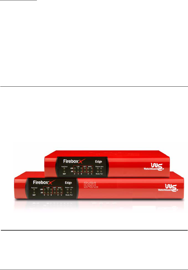
The WatchGuard® Firebox® X Edge e-Series is a firewall for small
organizations and branch offices. The Firebox X Edge e-Series product
line includes:
• Firebox X Edge e-Series
• Firebox X Edge e-Series Wireless
• Firebox X Edge e-Series DSL
Package Contents
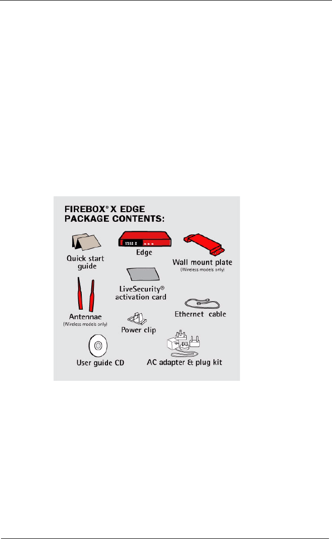
The Firebox® X Edge e-Series package includes:
• Hardware firewall
220 WatchGuard Firebox X Edge
• Firebox X Edge e-Series User Guide on CD-ROM
• Firebox X Edge
e-Series QuickStart Guide
• LiveSecurity® Service activation card
• Hardware warranty card
• AC adapter (12V/1.2A) with international plug kit. (For the
Firebox X Edge DSL models, a larger 12V/2.0A AC adapter is
supplied.)
• Power cable clip, to attach to the cable and connect to the side
of the Edge. This decreases the tension on the power cable.
• One straight-through cable
• Wall mount plate (wireless models only)
• Two antennae (wireless models only)

Specifications
User Guide 221
Specifications
The specifications for the Firebox® X Edge e-Series and the Firebox
X Edge e-Series Wireless are:
The specifications for the Firebox® X Edge e-Series DSL are:
Processor X Scale (ARM)
CPU 266 MHz
Memory: Flash 64 MB
Memory: RAM 128 MB
Ethernet interfaces 6 each 10/100
Serial ports 1 DB9
Power supply 12V/1.2A
Operating temperature 0 - 40 C
Environment Indoor use only
Dimensions for Firebox
X Edge e-Series
Dimensions for Firebox
X Edge e-Series
Wireless, including
antenna
Depth = 6.25 inches
Width = 7.4 inches
Height = 1.25 inches
Depth = 6.25 inches
Width = 10.9 inches
Height = 1.25 inches
Weight of Firebox X Edge
e-Series
Weight of Firebox X Edge
e-Series Wireless
1.9 U.S. pounds
2.0 U.S. pounds
Processor X Scale (ARM)
CPU 266 MHz
Memory: Flash 64 MB
Memory: RAM 128 MB
Ethernet interfaces 5 each 10/100
DSL interface 1 RJ11
Serial ports 1 DB9
Power supply 12V/2.0A
222 WatchGuard Firebox X Edge
Hardware Description
The Firebox® X Edge e-Series has a simple hardware architecture. All
indicator lights are on the front panel and all ports and connectors
are on the rear panel of the device.
Front panel
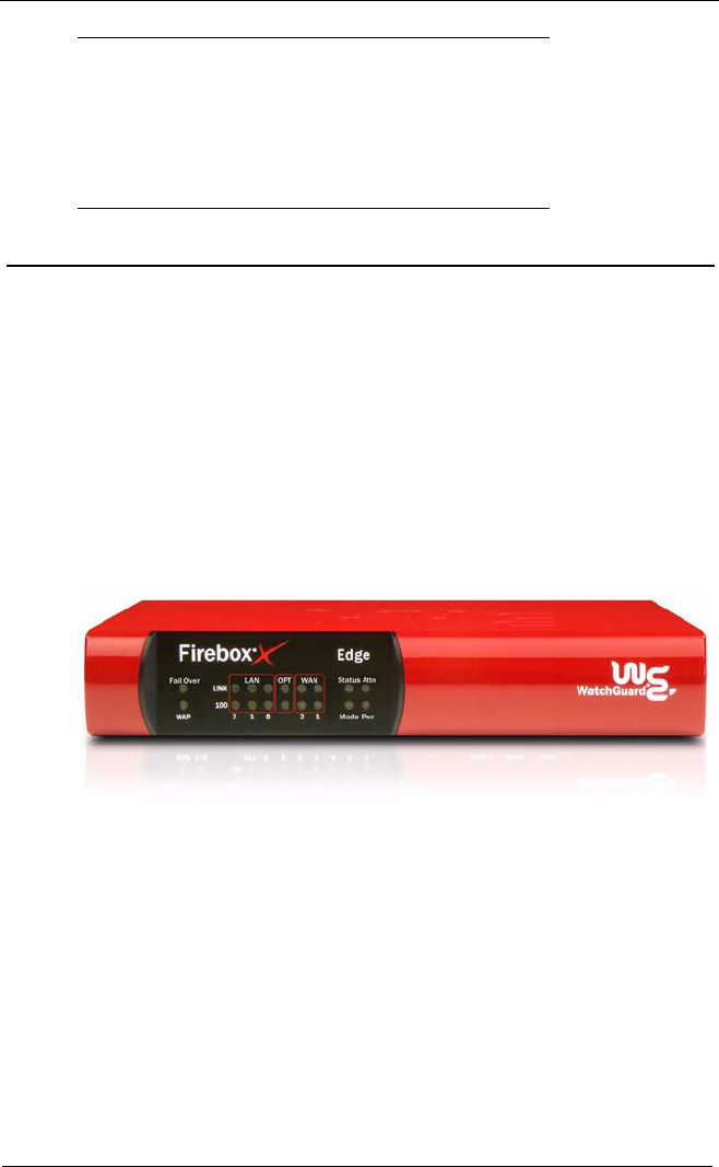
The front panel of the Firebox X Edge has 18 indicator lights to
show the link status. The top indicator light in each link pair comes
on when a link is made and flashes when traffic goes through the
related interface. The bottom indicator light in each pair comes on
when the link speed is 100 Mbps. If the bottom indicator light does
not come on, the link speed is 10 Mbps.
WAN 1, 2
Each WAN indicator shows the physical connection to the
external Ethernet interfaces. The light is yellow when traffic goes
through the related interface.
WAP
The WAP indicator shows that the Firebox X Edge is activated as
a wireless access point. The light is green when traffic goes
through the wireless interface on a Firebox X Edge e-Series
Wireless model.
Operating temperature 0 - 40 C
Environment Indoor use only
Dimensions for Firebox
X Edge e-Series DSL
Depth = 6.25 inches
Width = 10 inches
Height = 1.25 inches
Weight 2.0 U.S. pounds

Hardware Description
User Guide 223
Fail/Over
The Fail/Over indicator shows a WAN failover. The light is green
when there is a WAN failover from WAN1 to WAN2. The light
goes off when the external interface connection goes back to
WAN1.
Link
The link indicator shows a physical connection to a trusted
Ethernet interface. The trusted interfaces have the numbers 0
through 6. The light comes on when traffic goes through the
related interface.
100
When a trusted network interface operates at 100 Mbps, the
related 100 indicator light comes on. When it operates at 10
Mbps, the indicator light does not come on.
Status
The status indicator shows a management connection to the
Firebox X Edge. The light goes on when you use your browser to
connect to the Firebox X Edge configuration pages. The light
goes off a short time after you close your browser.
Mode
The mode indicator shows the status of the external network
connection. The light comes on when the Ethernet cable is
correctly connected to the WAN1 interface. The light is green if
the Firebox X Edge can connect to the external network and
send traffic. The light flashes if the Firebox X Edge cannot
connect to the external network and send traffic.
Attn
The Attn indicator is reserved for future use.
Power
The power indicator shows that the Firebox X Edge is on.
224 WatchGuard Firebox X Edge
Rear view
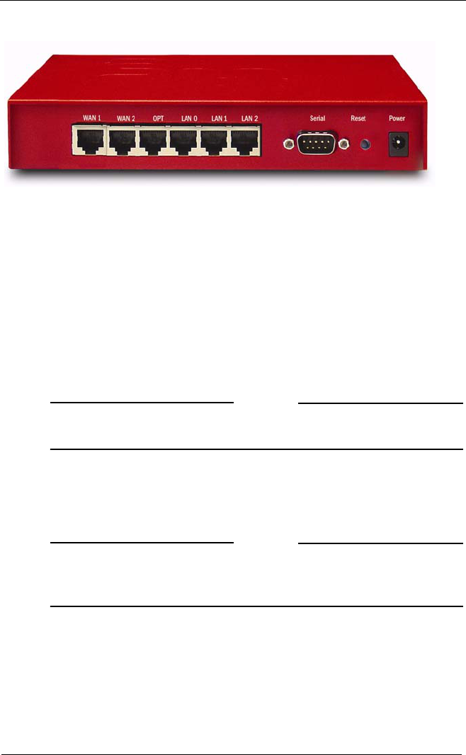
Serial port (DB9)
Use the serial port to connect an external modem to the
Firebox X Edge.
Ethernet interfaces LAN0 through LAN2
The Ethernet interfaces with the marks LAN0 through LAN2 are
for the trusted network.
OPT interface
This Ethernet interface is for the optional network.
WAN interfaces 1 and 2
The WAN1 and WAN2 interfaces are for external networks.
NOTE
If you use a Firebox X Edge e-Series DSL model, WAN1 is your
interface to the DSL connection.
Power input
A 12V/1.2A power supply is included with your Firebox X Edge.
Connect the AC adapter to the Firebox X Edge and to a power
source. The power supply tip is plus (+) polarity.
NOTE
If you use a Firebox X Edge e-Series DSL model, you must use the
12V/2.0A AC adapter that comes with the Firebox X Edge e-Series
DSL.
RESET button
To reset the Firebox X Edge, use the procedure in “Factory
Default Settings” on page 43.
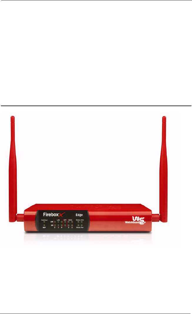
About the Firebox X Edge e-Series Wireless.
User Guide 225
Side panels
Computer lock slot
There is a slot for a computer lock on the two side panels of the
Firebox X Edge.
Antennae (wireless model only)
There are wireless antennae on the two side panels of the Firebox
X Edge e-Series Wireless models.
Wall mounting plate (wireless model only)
The wall mounting plate enables you to put the Firebox X Edge
in a good location to increase the range.
About the Firebox X Edge e-Series Wireless
.
The Firebox X Edge e-Series Wireless conforms to IEEE 802.11g/b
wireless LAN standards. Some key features that have an effect on
performance of an 802.11g/b wireless device include antenna direc-
tional gain, signal attenuation (path loss), and channel data rate.
Antenna directional gain
Antenna directional gain is based on the shape of the radiation pat-
tern around the antenna. The Firebox X Edge e-Series Wireless uses

226 WatchGuard Firebox X Edge
two 5.1 dBi swivel-mount whip antennas. The whip antenna has a
radiation pattern similar to a sphere that is squashed in the center. If
the antenna points up, the gain is largest in the horizontal direction
and less in the vertical direction.
Signal attenuation
Signal attenuation refers to the loss of signal power. It can be
caused by multi-path reflection. Multi-path reflection occurs when
RF signals that come to the receiver must move along more than
one path because of walls and other surfaces between the transmit-
ter and the receiver. It changes based on the phase at which the sig-
nals come, but signal strength can be increased or decreased by as
much as 30dB.
To decrease the effect of multi-path reflection, the Firebox X Edge
Wireless uses two antennas spaced some distance apart. This
decreases signal cancellation and allows the software to find the
best antenna to receive and transmit as conditions change.
Wireless clients usually have one antenna and are more sensitive to
the effects of antenna location. Because of this, the Firebox X Edge
e-Series Wireless can receive signals from a wireless client even if the
client does not receive signals from the Firebox X Edge.
Channel data rate
Channel data rate changes with the modulation type, which changes
based on conditions including noise and the distance between
transmitter and receiver. In general, the available data rates for an
IEEE 802.11g/b device change from 1 Mbps in the worst conditions
to 54 Mbps in the best conditions
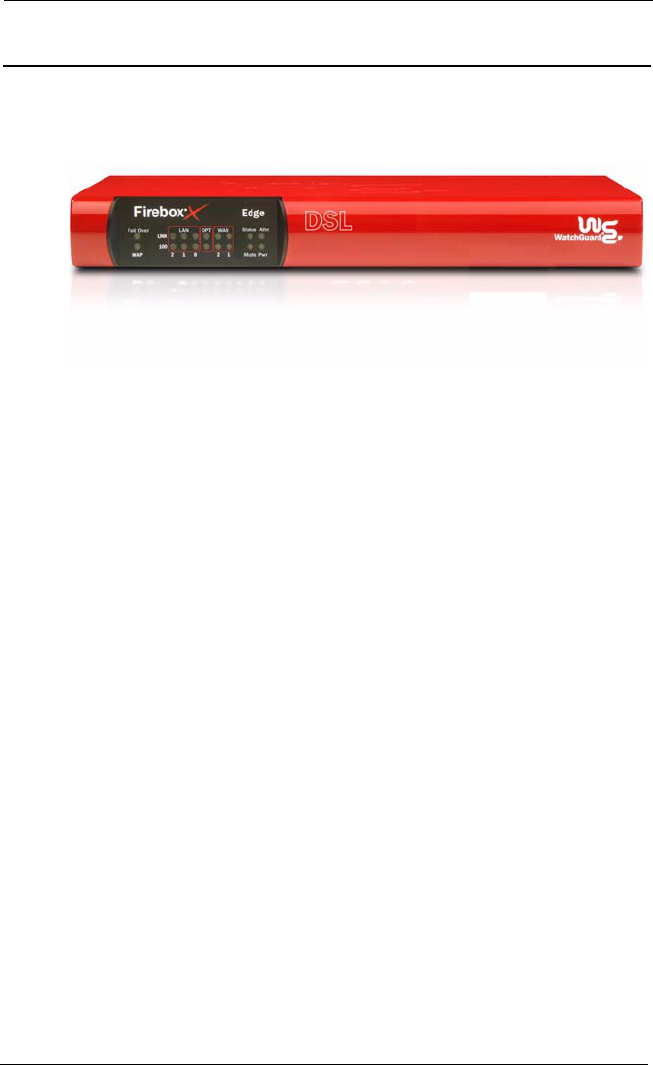
About the Firebox X Edge e-Series DSL
User Guide 227
About the Firebox X Edge e-Series DSL
The Firebox X Edge e-Series DSL connects your network to a high-
speed broadband Internet connection. This model includes an
internal SerComm integrated ADSL modem and one RJ11 port.
You can configure all available DSL properties using the web-based
interface of the Firebox X Edge.
The Firebox X Edge e-Series DSL is supplied in two hardware config-
urations:
Annex A
Annex A supports the public switched telephone network (PSTN)
environment. This configuration is used in the United States and
many other countries.
Annex B
Annex B supports the Integrated Services Digital Network (ISDN)
environment. This configuration is used in some European
countries.

228 WatchGuard Firebox X Edge