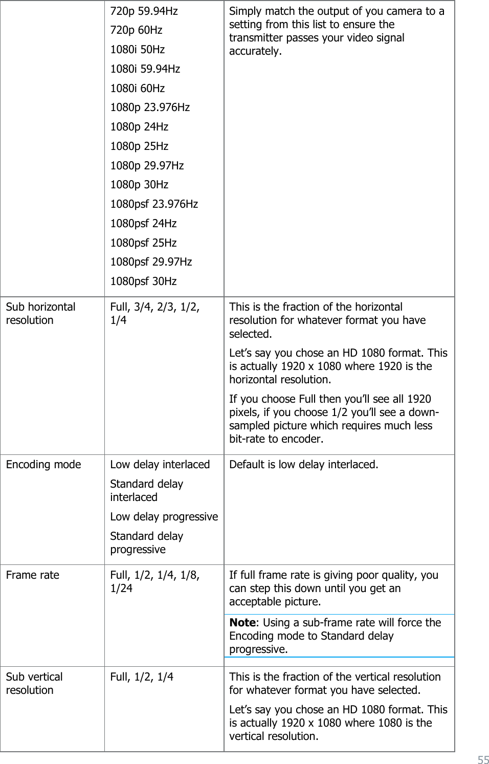
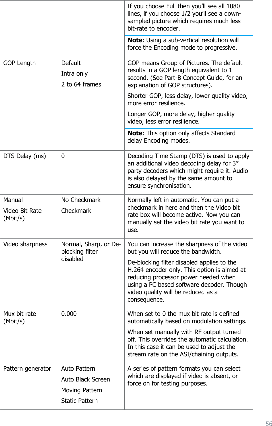
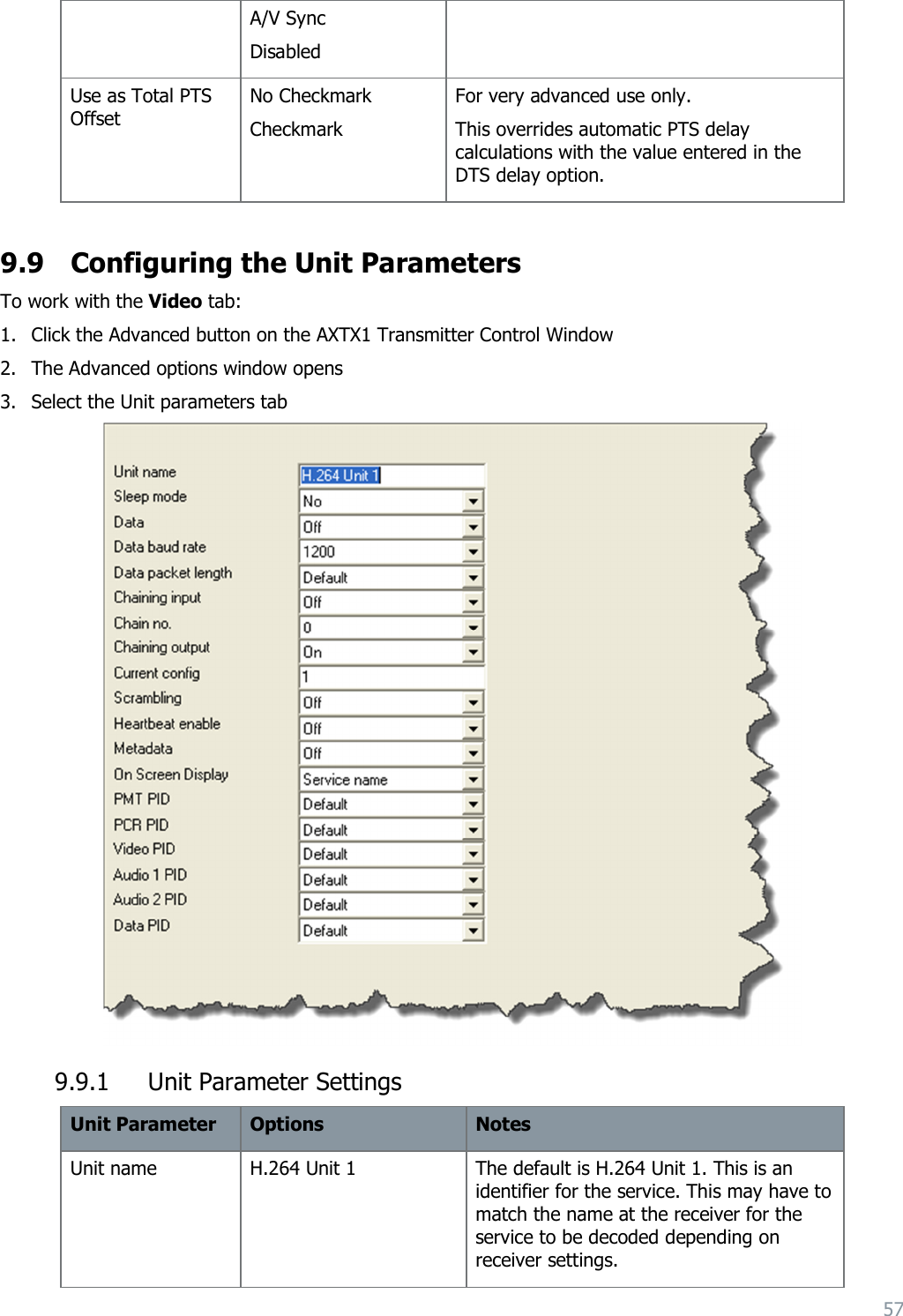
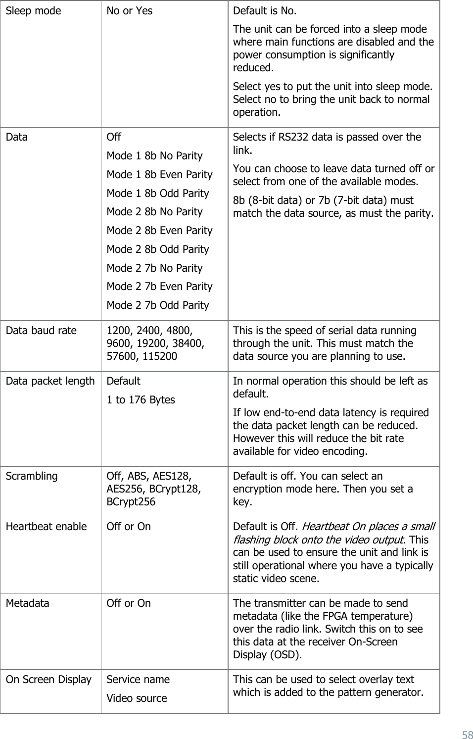
Wave Central AXIS5GTX 5.73 - 5.84GHz RF Microwave Transmitter User Manual Manual Rev4

Wave Central, LLC 5.73 - 5.84GHz RF Microwave Transmitter Manual Rev4

Manual Rev4

1    Axis Series – TX User and Programming Guide                                                         ATXT1                               AXTX1M – Mini                 AXTX1MB – Mini-B     Wave Central LLC 99 Garden Parkway, Suite C., Carlisle, PA 17013 +1 888 736 9283   www.wave-central.com
2   Contents Contents__________________________________________________________ 2 System Descriptions                             4   What are the Axis Series Transmitters?                                          5   Applications                                                            7   Variants and Options                                                      8   Main Connectors                                                          9   Applicable Unit Software                                                     14  Placards and Markings                                                        15    General                                                                 15   Exterior Placards and Marking System (AXTX1)                                      15   Interior Placards and Marking System                                             16   Exterior Color Schemes and Marking System                                        16  Cautions and Warnings                                                           17      Cautions and Warnings                                                                                                           17   Specific Absorption Rates (SAR) FCC Exemption                                                                         18   Health and Safety                                                        18    Panels, Displays, Alarm, Indicator and Controls                                  19        General                                                                19   Panel System – AXTX1xx                                                    19   Alarm System – AXTX1xx                                                    19   Indicator System – AXTX1xx                                                  19   Control Panel System – AXTX1xx                                              20  Connectivity                                                             21  General                                 21   Power - AXTX1                                                          21     Signal - AXTX1                                                             21     Control -  AXTX1                                                          21    Setting up your Transmitter                                                23    General                                                               23   Connecting Antennas                                                     23   Down Converter System                                                   23   Up Converter System                                                     23   Connecting Signals – AXTX1                                                 23   Connecting Power – AXTX1                                                 24   A Look at the Display – AXTA1                                               25   A Look at the TX Control System – AXTX1                                       25     A Look at the Menu Structure – AXTX1                                         27    Basic Operation                                                        29
3   General                                                               29   Starting and Stopping – AXTX1                                                 29   Working with the Control Panel – AXTX1                                           29    Advanced Operation                                                      34    General                                                               34   Encryption                                                             34  Control System                                                          37   General                                                               37   Connecting your PC to your Radio                                             37   Configuring Basic Settings                                                  39   Configuring the Radio                                                     47   Understanding the Unit Information Tab                                         47   Configuring the Modulation Parameters                                         48   Configuring the Audio Parameters                                             52   Configuring the Video Parameters                                             53   Configuration Unit Parameters                                               56  Care and Maintenance                                                    60    General                                                               60   Daily Care and Charging                                                   60   Cleaning                                                              60   Storage                                                               60   Repairs                                                               60  Appendix A-Glossary                                                     61   General                                                               61   Glossary                                                              61
4  1. System Descriptions The subject equipment of this User Guide is identified as follows: Equipment Title Part Number Full Size Camera Back Transmitter AXTX1  Miniature Transmitter AXTX1M Miniature B Transmitter AXTX1MB    Figure 1-1 – AXTX1: Camera Back Transmitter    Figure 1-2a – AXTX1M - Mini Transmitter
5      Figure 1-3b – AXTX1MB: Mini-B Transmitter   1.1 What are the Axis Series Transmitters? The  new  Axis  series  transmitter  comes  in  three  different  packages  designed  to  suit  the  needs  of  many different types of applications.   These transmitters both offer excellent coverage,  low delay  performance and  multiple  format/frame  rate  capabilities  that  enable  users  to  acquire  stunning  images  via  a  wireless connection,  at  extended  non  line  of  sight  ranges.  By  using  2nd  generation  MPEG4  H.264  compression technology,  users  can  now  deploy  2  or  3  cameras  within  the  same  bandwidth  previously  required  by  a single MPEG2 system. All modes of DVB-T modulation are also supported. The increased compression and efficiency of the MPEG4 H.264 encoder offers users additional range with the  added  benefit  of  small  size,  low  latency  and  low  power  consumption.  In  particular,  high  quality  HD transmissions  are  now  possible  using  40%  lower  band  width  requirements  than  those  of  conventional MPEG2 systems need, allowing for HD transmission in a single 8MHz DVB-T channel and also being able to use very robust error correction and modulation settings.   Built with a solid aluminum housing, the ability to  transmit  images  in  a  non-line  of  sight  environment  at  ranges  well  over  a  ½  mile  and  its  low  delay capabilities makes this transmitter a very formidable workhorse to suit almost all your RF needs. The AXTX1 camera back transmitter is a rugged, digital video transmitter, ideal for Sports, ENG News and other  Broadcast  applications  and  the  AXTX1M-Mini  and  AXTX1MB-Mini  B  are  smaller  packaged  version geared towards Digital Cinema and Video Assist applications.  The  AXTX1  camera  back  transmitter  can  have  either  Anton  Bauer  or  Sony  “V”  Mount  battery  plates installed  to  facilitate  easy  mounting  to  most  camera  types.  The  AXTX1M-Mini has  a  Sony  “mini”  battery mount, as well as a threaded mounting hole on the bottom of the unit to attach to a wide range of camera brackets  for  easy  mounting  of  the  AXTX1-Mini  to  many  different  style  cameras.  While  the  Axis  series transmitters can be operated with almost any receiver that supports DVB-T signals, we recommend using it with  the  Wave  Central  AXRX1  receiver.  The AXRX1  receiver  is  available  in  many  different  configurations with options for 2-way, 4-way, 6-way and 8-way diversity.
6   1.2 Features and Benefits It can be very useful to understand how the features of the unit yield tangible benefits to you. This table summarizes these features and, more importantly, the benefits.  Features and Benefits Table Feature Benefit to you Digital COFDM Modulation.  Excellent performance - Resistant to multipath interference, delivers high quality video and audio, even in non-line of sight operation. Low Delay H.264 SD & HD encoding. Robust transmission and minimal latency, switches easily with wired cameras. Compliant DVB-T 6/7/8MHz.  True multi-mode operation - Simple integration with your current equipment. ASI input and output. Allows for different types of applications: RF Transmitter or Portable H.264 Encoder. High Efficiency 100mW RF Amp (Cool Operation) Excellent range in non-line of sight environments like stadiums and arenas. Compact and Power Efficient Transmitters Low power consumption, 10W Two models allow for the type of transmitter just where you need it. Sized right to ensure the success of your operation.  HD-SDI/SDI with embedded audio input HDMI input with embedded audio input video input Easy connections connect to your current cameras. Added flexibility of using HD consumer level HDMI cameras. Choice of different licensed and un-licensed frequency bands. (1.4, 2, 5.8, 6.4, 6.8, 7GHz Available) Choose the frequency that best suits your operations. Select license free bands for some operations. Avoid cluttered parts of the licensed radio spectrum. Sixteen Presets Available You can establish 16 different parameters to include: Preset frequencies, COFDM constellations, video and audio settings, into any of sixteen presets. Configure the transmitter once and then users can select from the front panel. Display Screen and PC GUI  Software Driven - Simple and fast to deploy and operate – Saves you time and minimizes operator error. AXTX1M1 Camera Back Transmitter Suitable for Sports, ENG News and other Broadcast applications
7  AXTX1M Mini about the size of an iPhone Digital Cinema and Video Assist applications AXTX1MB Mini-B Digital Cinema and Video Assist applications 1.3 Applications The Broadcast Transmitter has been designed to operate in multiple roles in many environments. Here are some examples: 1.1 Professional Camera Back Applications – Sports and News We can supply either Anton Bauer or Sony “V” mounting plates that enable the camera back transmitter to be directly connected to professional cameras. The Sony “V” mount, for example enables the transmitter to be mounted directly onto cameras such as the SONY PDW Series Cameras and Thomson 8000 Series.  The transmitter mounts between the camera and the battery.  The camera is powered from the battery, through the AXTX1 transmitter, powering both units.  The AXTX1 is also available with Anton Bauer connectors to directly mount onto Panasonic and Ikegami ENG type cameras.  1.2 Helicopter Integration for Sports, News and Traffic Coverage A variety of installation options can be made much simpler and easier to operate, by using either of the AXTX1 transmitters.  By having ASI in/out connectors, the AXTX1 allows for specific “Heli-Tele” configurations and options. 1. ASI out: Can be used to encode an HDSDI signal from a gimbal mounted camera to ASI, which is then fed to an RF amplifier and directly coupled to an antenna. (Minimal RF loss) 2. ASI in: Can be used in an aerial “re-trans” system.  Signals sent up to a helicopter from ground vehicles and then sent to remote receive sites, miles away. 3. The small lightweight AXTX1-Mini is perfectly suited for these types of applications. 1.2.1 System Integration into Vehicles or Aircraft Users should be aware of the following issues when integrating the equipment into vehicles. 1. For the additional range required in vehicle applications, the use of amplifiers should be considered.  Interconnection between the transmitter and any power amplifier should be kept as short as possible, but where this is not possible, special attention should be taken to use only low loss cables.  2. Long cable runs from the RF output to the antenna should be avoided, for maximum RF output. 3. The antenna should be mounted vertically ideally, and exposed to free space. 4. The equipment should be supplied with a clean supply in the range 7V to 18V and capable of 1.10A maximum at 12VDC.  Care should be taken to avoid direct supply from the vehicle 12V which can be very noisy. Power conversion will be required for 24V vehicles. 5. The video input can be connected across long video cable lengths so remotely mounted cameras should pose no problem. 6. Insure for proper ventilation of equipment, especially RF transmitter and Amplifiers.
8   1.3 Variants and Options 1.3.1 Variants – AXTX1 Camera Back Transmitter, with Camera Paint  There are several major variants of the AXTX1 Camera Back Transmitter:    Operating Frequency Band Model/Part Number AXTX1 CBT 1.990-2.492GHz 100mW AXTX1 - 2G AXTX1 CBT 5.730-5.840GHz 100mW AXTX1 - 5G AXTX1 CBT 6.436-7.120GHz 100mW AXTX1 - 7G  1.3.2 Variants – AXTX1M – Mini TX There are also three variants of the AXTX1M – Mini TX Transmitter: Equipment Title Part Number AXTX1 Mini TX 1.990-2.492GHz 100mW AXTX1M - 2G AXTX1 Mini TX 5.730-5.840GHz 100mW AXTX1M - 5G AXTX1 Mini TX 6.436-7.120GHz 100mW AXTX1M - 7G  1.3.3 Variants – AXTX1MB – Mini-B TX Equipment Title Part Number AXTX1 Mini-B TX 1.990-2.492GHz 100mW AXTX1MB - 2G AXTX1 Mini-B TX 5.730-5.840GHz 100mW AXTX1MB - 5G AXTX1 Mini-B TX 6.436-7.120GHz 100mW AXTX1MB - 7G  1.3.4 Accessory Options Equipment Title Part Number V-Mount Battery Plates (AXTX1 only) TX-VBAT AB Battery Plates (AXTX1 only) TX-ABBAT 1.3.5 Licensing Options Encryption:  AES 128 is available upon request
9  1.4 Main Connectors Here are the unit’s main connectors: 1.4.1 AXTX1 Broadcast Transmitter – Front View  Figure 1-4 AXTX1 Front View Connectors Serial Item 1 SMA Connector for 450MHz Camera Control Antenna. 2 N Connector for AXTX1 Main RF Antenna. 3 Tally Connector. 1 2 4 7 3 5 6
10  4 XLR Connectors (x2) Analog Audio In. 5 LEMO 4 pin female connector for CCU, camera paint system (RS-232) 6 Hirose 6 pin female connector for CCU, camera paint system (RS-422) 7 BNC Connector for HD/SDI Video Input.  1.4.2 AXTX1 Broadcast Transmitter - Bottom View   Figure 1-5 AXTX1 Bottom Connectors  Serial Item 1 Unit’s Internal Fan On/Off Button. (For limited fan off operation) 2 USB Programming Connector to Program TX Unit. 3 LEMO 4Pin Connector for External DC Power for Main Unit. 4 BNC ASI Video Input. 5 BNC ASI Video Output.        1 2 3 4 5
11  1.4.3 AXTX1 Broadcast Transmitter - Top View         Figure 1-4 AXTX1 Top Connectors  Serial Item 1 DC Power NOT USED 2 Type N Connector female, RF Output 3 RF output Indicator 4 SMA female connector for Paint System Antenna           1 2 3 4
12  1.4.4 AXTX1 Broadcast Transmitter – Left Side View     Figure 1-5 AXTX1 Left Side View  Serial Item 1 Transmitter Control Panel and Display 2 Camera Mount Plate 3 Camera/Transmitter Battery Mount Plate 4 Transmitter/Paint Main DC Power Switch        1 3 4 2
13  1.4.5 AXTX1 Broadcast Transmitter – Right Side View   Figure 1-6 AXTX1 Right Side View Serial Item 1 Camera Control Unit (CCU) Panel and Display for Paint 2 Indicator, Paint Data connection with base station 3 HDMI Type A input with embedded audio input and video input        1 2 3
14  1.5 Applicable Unit Software  Each Transmitter has two software elements:  Firmware that runs the device, via board level FPGA’s. (Field Programmable Gate Array)  And Control Application that is run from a Windows based PC, external of the transmitter. 1.5.1 Internal Software Although much of the transmitter is built up of hardware components, many of the sophisticated features are implemented via firmware programmed into the FPGA’s. When you perform a firmware upgrade, a complete firmware installation package is provided which contains all the required upgrade codes. 1.5.2 Control Application For customized operation and unit configurations, connecting to a PC and running the transmitter Control Application will give the user much more global command control of the unit’s settings and parameters. Here is a screen shot of what the Transmitter Control Application looks like:  Figure 1-6 Transmitter Control Application
15  2 . Placards and Markings Which model do I have? What is its Serial Number? The information covering placards, labels, markings, etc., showing the part number, legend and location of each placard, label, or marking required for safety or maintenance significant information. 2.1 General You’ll need to be able to quickly identify equipment types and serial numbers you have and at what frequencies your systems are designed to work. You may need to find the Serial Number during a support call for example. The simplest way is to check the placards and markings on the units and this section shows you how to decode them. The AXTX1 is shown as an example. 2.2 Exterior Placards and Marking System (AXTX1) The system information that includes placards, labels, and markings required for servicing instructions, inspections, cautions, warnings, etc. The outside of each Broadcast Transmitter unit is marked with several placards:  Serial Number Placard  Product Placard  Warranty Void Placard 2.2.1 Serial Number Placard   Figure 2-1 Serial Number Placard AXTX1
16  2.2.2 Product Operating Range and Warranty Void Placard    Figure 2-2 AXTX1 Product and Warranty Void Placard  Serial Item 1 Product code and frequency range, 5.5GHz to 6.0GHz in this example. 2 Warranty Void, if seal is damaged.   2.3 Interior Placards and Marking System The system information covering placards, labels, and markings required for general interior and emergency information, instructions, cautions, warnings, etc. There are no interior placards and markings that will concern the operator of this unit. 2.4 Exterior Color Schemes and Marking System This system information includes specifications and requirements covering exterior color and related markings. 2.4.1 Enclosure Color The main enclosure is anodized in black. 2.4.2 Panel Markings The markings on the Axis Series are in white. 1 2
17  3 . Cautions and Warnings 3.1 Cautions and Warnings Serial Area Note 1 Enclosures Do not remove any factory installed screws or fastenings. Damage to the units may result and void any warranties.  Only authorised, trained personnel should open the product. There are no functions that required the user to gain access to the interior of the product. There are no user serviceable parts inside. 2 Maintenance Other than cleaning, no scheduled maintenance is required to ensure proper function of the unit. 3 Environment The equipment should not be used in hazardous or corrosive atmospheres. Users are reminded of the necessity of complying with restrictions regarding the use of radio devices in fuel depots, chemical plants and locations where explosives are stored and/or used. 4 Power Supply Ensure that the power supply arrangements are adequate to meet the stated requirements of each product. Observe all electrical safety precautions. 5 Electro Static Discharge (ESD) Precautions  ESD guidelines must be followed for this electrostatic sensitive device. 6 Lightning Strike There is a risk of lightning strike to antennas. The equipment should not be assembled in an area at the time of lightning activity. Antennas should be adequately protected from lightning strikes. 7 Working at Height Observe caution when locating the device at height, for example on a mast. Ensure the unit is well secured to prevent it falling and injuring personnel. 8 Risk of Eye Injury Care should be taken to avoid eye contact with the antennas.  9 Cables Connecting cables should not be positioned where they are likely to become damaged or were they may present a trip hazard. 10 Thermal Control System Any powered device will always produce heat as a by-product of its operation. If you operate this device in an enclosed space you must ensure it has adequate airflow to keep it cool. Also, if worn close to the body, care must be taken to protect the operator from excessive temperatures.
18  Serial Area Note 11 RF Emission System When using this device please ensure a distance of 20cm is maintained between your device and your body while the device is transmitting. 12 Aircraft Safety Use of this equipment on board aircraft is strictly forbidden. Use of radio transmitter equipment in an aircraft can endanger navigation and other systems.  3.2 Specific Absorption Rates (SAR) FCC Exemption  This device is excluded from SAR testing since the separation distance is more than 20cm per KDB 447498
19  4 . Panels, Displays, Controls, Indicators and Alarms  4.1 General You’ll need to be able to find all the interface connections and controls on the unit. You’ll also need to be able to identify and interpret any alarms or indicators. This section will help you identify all these features. Each Axis-Series Broadcast Transmitter has several panels which contain all the interface connections for the units and the controls and indicators. There is an operational control panel on one panel of the unit. The next section describes the transmitter control panel for the all Axis Series Broadcast Transmitters.  4.2 Panel System – AXTX1  The AXTX1 has two significant display panels:   Transmitter Control Panel   CCU, Camera Control Unit, Paint for AXTX1 only. 4.3 Alarm System – AXTX1 Series The right LED indicator is an alarm indicator.  4.4 Indicator System – AXTX1 Series User information is displayed on the display screen or on the Control application. Two LED’s are located above the TX indicator panel screen. The GREEN LED indicates, control panel is communicating with the main board. The right LED indicator illuminates RED for an alarm, as indicated below.   Figure 2-3 AXTX1-Series TX Control Panel     TX
20  4.5 Control Panel System – AXTX1 Series Transmitters           Cancel/Back                              Joystick/Confirm  Figure 2-3a AXTX1-Series TX Control Panel  The control panel located on the right panel has two push buttons. Here’s what they do: 4.5.1 Joystick/Confirm Button (2) Button Does this… Joystick/Confirm Button Move the joystick for UP, DOWN, LEFT and RIGHT. Press the joystick for ENTER.  4.5.2 Cancel/Back Button (3) Button Does this… Cancel/Back Button Press to cancel action or go back one level. TX
21  5 . Connectivity What are all the connectivity options? 5.1 General You’ll need a means of interconnecting equipment in the communication system for the purpose of transporting energy and /or communication signals. This section will help you identify all these wires, waveguides, glass-fibers, connecting elements, etc. The Broadcast Transmitter provides connectivity for  Power  Signal (such as video, audio and data)  Control (using your PC) The next section describes the connectivity options for the AXTX1 Broadcast Transmitter... 5.2 Power – AXTX1  Connecting systems designed mainly for transporting electric power to the communication system equipment. This includes connecting elements, wires, fuses, over-voltage protection and breakers. 5.2.1 DC Power The AXTX1 does not have any batteries on board. The unit accepts 6-17VDC through the power interface on the bottom panel (reverse polarity protected). This is a LEMO 4-pin female connector, marked DC IN. 5.2.2 AC Power You can purchase an optional AC Adapter to power the AXTX1. 5.3 Signal – AXTX1  Describes connecting systems designed mainly for transporting the communication signals. This could be video, audio, data (RS232 or RS485) and IP. 5.3.1 Video The unit accepts video signals through the Video interface on the front panel. This is a BNC female connectors marked HD/SDI. This cable has another BNC plug where you can connect your video source. Alternatively the HDMI interface on the right hand side panel can be used. This is a HDMI Type A female recessed connector, adjacent to the Paint Data LED indicator. 5.3.1.1 ASI In and ASI Out There are two BNC connectors mounted on the bottom, marked ASI IN and ASI OUT 5.3.2 Audio The unit accepts audio signals through the two XLR female connectors on the front panel. These two connectors are marked Audio 1 and Audio 2. Alternatively embedded digital audio can be extracted from HD/SDI or HDMI sources.
22  5.3.3 Data The unit  accepts  Camera  data  signals through  the DATA  and PAINT interface  on  the  front  panel.  The DATA is a LEMO 4-pin female connector; RS-232. The PAINT is a Hirose 6 female connector; RS-422 Your supplied Data cable assembly fits in here. A specific cable must be for the camera that will be control. Supported cameras are Sony, Grass Valley LDX, Ikegami, Panasonic and Hitachi. 5.3.4 IP The AXTX1 does not carry IP signals. 5.4 Control – AXTX1  Describes connecting systems designed mainly for controlling and configuring the radio units. The AXTX1 uses Serial Control Data (over USB) to communicate with a Personal Computer for programming. The unit accepts Control signals through the USB connector on the bottom panel.  Your supplied Control cable assembly fits in here. This cable has a USB 4-pin plug where you can connect your Personal Computer. 5.4.1 IP Control The AXTX1 does not use IP control. 5.4.2 Paint This unit accepts paint/data from the camera remote paint system via the built-in wireless receiver system through the Data and PAINT interface connectors on the front panel. This is a LEMO 4 pin female for RS-232 data connector This is a Hirose 6 pin female for RS-422 data connector
23  6 . Setting up your Transmitter 6.1 General These guidelines will help you install and set up your system. As a general rule we connect in order:  Antennas  Signals  Power 6.2 Connecting Antennas Each AXTX1 unit requires one antenna. The antenna must be fitted before the unit is placed into RF mode.  6.2.1 Assembling the Antenna System AXTX1 units normally use simple Omni-antennas and do not require any rigging. Naturally, it is possible to use a variety of antenna types for specialist applications.  6.2.2 Attaching the Antenna You’ll need an AXTX1 and one antenna. An ANT2-200250, 2dBI flexi N-Type mount antenna 2.00 to 2.50GHz would be a typical example for an S-Band variant. 1. Connect the antenna to the N-Type N connector on the top panel of the transmitter unit. 2. Do not over tighten the antenna – hand tight only! CAUTION: Antennas should be connected directly to the unit. If you have to use cables between the antennas and the AXTX1 (in a mobile application for example), keep them short and use very high quality cable. Note: There are many types of antenna that can be fitted to the AXTX1 unit. Your antennas may look different from those in this guide. 6.2.3 Antenna Polarization COFDM links are very robust and are tolerant to changes in antenna position, however, it is important to try and keep the antennas in the same plane if possible. The antennas used with the COFDM links are normally linearly polarized. 6.3 Down Converter System There are no down converters used with transmitters. 6.4 Up converter System The Up converter board is inside the enclosure of the transmitter and has no user serviceable parts. There are no operational controls on the board. 6.5 Connecting Signals – AXTX1 6.5.1 Connecting Video Signals For a composite or SDI input you’ll need a Video source, AXTX1 and a CA0006 Video cable assembly.
24  1. Connect one BNC 2-way plug to the HD/SDI connector of the AXTX1. 2. Connect the other BNC 2-way plug to the video source. 3. Switch on the Video source. 4. Ensure the radio in configured to accept HD or SDI video.  For a HDMI input you’ll need a Video source, AXTX1 and a HDMI cable suitable for the video source with a Type A plug at the other end.  1. Connect one HDMI Type A plug to the HDMI In connector of the right side of the AXTX1. 2. Connect the other HDMI plug to the video source. 3. Switch on the Video source. 4. Ensure the radio is configured to accept HDMI video. 6.5.2 Connecting Audio Signals 1.  Connect the analog audio source to the XLR audio 1 and/or audio 2 inputs. 2.  Ensure the radio is configured to send Analog audio (Audio is set to embedded source by default).  For embedded audio input you’ll need a digital Video input setup as above and a Video source which embeds audio.  1. Connect Video signals as described above. 2. Configure the video source to provide embedded audio. 3. Ensure the radio is configured to send Embedded audio. 6.5.3 Connecting Camera DATA and PAINT signals Depending upon camera being used, either the LEMO 4-pin (RS-232) labelled DATA or the Hirose 6-pin (RS-422) labelled PAINT would be used.  1. Connect the DB-9 cable from the RCP-TX-IDU 2. Connect the D-Type 9-way plug to the camera control unit to the corresponding DATA or PAINT connectors depending upon camera being used. 3. Switch on the Camera CCU data source. 6.6 Connecting Power – AXTX1  The AXTX1 requires 12VDC. The unit can be powered from DC by using suitable batteries or a vehicle power source. Take care that the vehicle supply is within limits for this unit. Aircraft for example, normally use 28VDC supplies. CAUTION: When using a 12VDC supply ensure the polarity is correct. The red banana plug should be connected to the positive terminal. The Black banana plug should be connected to negative terminal. 6.6.1 Connecting DC Power You’ll need a 12VDC power source.    1. Connect the LEMO 4-pin plug to the DC IN connector of the bottom of the AXTX1.
25  2. The other of the LEMO cable has a male XRL 4 pin plug that attaches to 12VDC power supply capable of at least 2 Amps 6.6.2 Connecting AC Power You’ll require a 12VDC Power Supply (optional) Adapter for 120VAC input and an AXTX1.   1. Connect the LEMO 4-pin female connector to the DC IN connector on the AXTX1. The other of the LEMO cable has a male XRL 4 pin plug that attaches to the optional 120VAC Adapter. 2. Connect the IEC AC 3-way female plug to the IEC AC 3-pin male socket on the AC Adapter. 3. Connect the IEC AC plug to your local AC supply and switch on. 4. On the display screen, you’ll see the text illuminate. 6.7 A Look at the Display – AXTX1  The AXTX1 is equipped with a display screen on the right panel. You can control what is displayed on this screen using the Control Panel buttons described earlier.  Figure 6-1 AXTX1 Display Screen and Control Buttons  6.8 A Look at the TX Control System – AXTX1           Cancel/Back                              Joystick/Confirm Figure 6-2 AXTX1-Series TX Control Panel  TX TX
26     The control panel located on the right panel has two push buttons. Here’s what they do: 6.8.1 Joystick/Confirm Button (2) Button Does this… Joystick/Confirm Button Move the joystick for UP, DOWN, LEFT and RIGHT. Press the joystick for ENTER. 6.8.2 Cancel/Back Button (3) Button Does this… Cancel/Back Button Press to cancel action or go back one level.
27  6.9 A Look at the Menu Structure – AXTX1  6.9.1 Display Screen, Menu Structure
28  6.9.2 Display Screen, Menu Functions Menu Sub-Menu Function Unit Status N/A Encoder/modulator board status. Unit Control RF RF output related settings and preset range modes. DVB-T Modulation options relevant to DVB-T mode. Video In Video input interface settings. Video Enc Video encoder options. Audio 1 Audio encoder 1 settings. Options not starting with “Aud 1” are shared for both encoders. Audio 2 Audio encoder 1 settings. Options not starting with “Aud 2" are shared for both encoders. ASI ASI IO and advanced chaining setup. Scram Scrambling options and keys. Data Data channel settings. Service Service names and manual PID setup. Config Config number and restore default option. Local Settings N/A Display screen settings and status.
29  7 . Basic Operation 7.1 General This chapter covers normal day to day operations of a fully configured AXTX1 system. Once installed and configured the AXTX1 is easy to operate. These guidelines will help you perform basic operations on your Broadcast Transmitter. Note: If you are working with a new system or you need to change any of the configurations, look at the Advanced Operation and Control System chapters later in this guide. 7.2 Starting and Stopping – AXTX1  AXTX1 units don’t have power switches – you simply apply power to them and they will start up. 7.2.1 Powering Up – AXTX1  You’ll need a fully configured AXTX1.  1. Switch on the AXTX1 using the procedure 7-6 above. 2. On the display screen, you’ll see the text illuminate. 7.2.2 Powering Up – AXTX1  You’ll need a fully configured AXTX1.  1. Supply power to the AXTX1 using the procedure 7-7 above. 2. Power is now immediately available to the camera. 3. Switch the toggle switch to ON to power the transmitter. 4. On the display screen, you’ll see the text illuminate. 7.2.3 Shutting Down – AXTX1  It can be important to shut down a system gracefully. This ensures that all processes are terminated correctly and not data or settings are lost. 1. Ensure the unit is not in sleep mode. 2. Switch to On/Off switch to OFF 3. On the display screen, you’ll see the text go out. 4. Disconnect the power cable from the AXTX1. 5. The system is shut down safely.   7.3 Working with the Control Panel – AXTX1  The broadcast transmitter has a control panel to enable you to change modes, configurations and to control the RF setting. 7.3.1 Selecting the Root Menu 1. Power on the AXTX1  2. Let the unit initialize
30  3. You’ll see the frequency and the Root menu on the display screen:  Figure 7-1 Selecting the Root Menu  7.3.2 Selecting a Configuration You’ll need a powered AXTX1 set at the root menu as in 8-3-1 above. 1. Push up/down on the Joystick button to select a new configuration number 2.  Your new configuration appears highlighted. 3. Push the Joystick / Confirm button to select the new configuration 4. The highlight disappears and your new configuration number is displayed. Note: Changing a configuration turns off the RF output to prevent accidental transmission and potential interference. The RF output must manually be re-enabled once the user is confident that the correct configuration has been selected.   Figure 7-2 Selecting a Configuration  7.3.3 Selecting RF on or off  You’ll need a powered AXTX1 set at the root menu as in 8-3-1 above. 1. Push the Joystick / Confirm button for two seconds. 2. The RF caption will toggle to on.
31  3. Push the Joystick / Confirm button for two seconds to turn the RF off  Figure 7-3 Selecting RF on or off 7.3.4 Using the Unit Status Menu You’ll need a powered AXTX1 set at the root menu as in 8-3-1 above. 1. Push Cancel / Back button  2. You’ll see the frequency and the Unit Status: menu on the display screen 3. Push the Joystick/Confirm button to enter the Unit Status menu 4. You’ll see Vid Lock, which is the first item in the Unit Status menu 5. Use the Joystick/Confirm button up/down arrows to scroll through the menu items.  Figure 7-4 Using the Unit Status Menu Unit Status indicators are: Menu Sub-Menu Typical Value Notes Unit Status Vid Lock No or Yes
32   Vid Rate 8.522Mbps   ASI Lock No or Yes   S/W Ver 1.4   Serial e03a095e   Battery 12.0V May show Reply Error on Units where battery monitoring are not available.   FPGA Ver 00023140   FPGA Temp 50C Expect running internal temperature of 50-75°C depending on environment.  Note: Don’t worry if you accidentally press the Joystick/Confirm button when you are moving about the Unit Status menu. It really just shows you the current settings and will not allow you to change them. 7.3.5 Using the Unit Control Menu You’ll need a powered AXTX1 set at the root menu as in 8-3-1 above. 1. Push Cancel / Back button  2. You’ll see the frequency and the Unit Status: menu on the display screen 3. Use the Joystick/Confirm button down arrow to scroll down to Unit Control 4. Push the Joystick/Confirm button to enter the Unit Control menu 5. You’ll see RF, which is the first item in the Unit Control menu 6. Use the Joystick/Confirm button to move up and down the Unit Control menu 7. When you find a Config you want to change, press the Joystick/Confirm button to select that Config for editing. 8. Use the Joystick/Confirm button to move up and down the possible settings 9. Press the Joystick/Confirm button to save the new setting 10. Press the Joystick/Confirm button again to confirm the new setting 11. When done, press the Cancel/Back button to return to the top menu  Here are some of the settings you can configure from the menu just for the RF sub menu. For a full list, take a look at the menu at 7-9-1.  Menu Sub-Menu Sub-Sub-Menu Typical Value Unit Control RF Freq 2031.50MHz   RF Out On   B/W 8MHz   TX Mode Off
33    RF Power 100mW   RF Atten 0.00dB 7.3.6 Using the Local Settings Menu You’ll need a powered AXTX1 set at the root menu as in 8-3-1 above. 1. Push Cancel / Back button  2. You’ll see the frequency and the Unit Status: menu on the display screen 3. Use the Joystick/Confirm button down arrow to scroll down to Local Settings 4. Push the Joystick/Confirm button to enter the Local Settings menu 5. You’ll see Serial, which is the first item in the Local Settings menu 6. Use the Joystick/Confirm button to move up and down the Local Settings menu 7. When you find a Config you want to change, press the Joystick/Confirm button to select that Config for editing. 8. Use the Joystick/Confirm button to move up and down the possible settings 9. Press the Joystick/Confirm button to save the new setting 10. Press the Joystick/Confirm button again to confirm the new setting 11. When done, press the Cancel/Back button to return to the top menu  For a full list of the settings you can configure from the Local Settings menu, take a look at the menu at 7-9-1.  7.3.7 Using the Control Panel Button Lock Feature You’ll need a powered AXTX1. 1. Hold Joystick/Confirm button then press Cancel / Back button for about 8 sec 2. The Control Panel buttons will lock 3. A key appears on the Display screen to show that the panel is locked 4. Press and hold again to unlock the Control Panel    Note: You must press the Joystick/Confirm button just before the Cancel / Back button to avoid menu interaction. Note: You can lock or unlock the Control Panel from anywhere in the menu structure.
34  8 . Advanced Operation 8.1 General These guidelines will help you perform advanced operations on your radio. 8.2 Encryption Your material is a valuable asset to your organization and naturally you don’t want others intercepting your radio signal. To do this, all that they need is a radio receiver that operates in the same mode and on the same frequency you are using to transmit. 8.2.1 Encryption System If the AES scrambling option has been purchased for the Axis system in use, then it is possible to encrypt the link. Both Bcrypt128 and BCrypt256 are license-controlled features. You’ll need to encrypt the traffic leaving the transmitter and set up the receiver for decrypt. 8.2.2 Switching on the Transmitter Encryption Here’s how you set up Encryption on the device: 1. Connect your radio to your PC and run the control application (see Ch10, Control System) 2. In the Scrambling combo box click the drop-down arrow and select an encryption type. (AES128 for example). 3. Click the Encryption button (yellow key icon). 4. The Write encryption key dialog box will open 5. In the Key type combo box click the drop-down arrow and select the key type you want to write. (Should match the key type you chose in step 1). 6. In the AES128 key text box, type the encryption key you want to use. 7. Click the OK button.
35   Figure 8-1 Switching on Transmitter Encryption 8.2.3 Number of Encryption Key Characters Required In our example above we used AES128 encryption. This needed a key of 32 characters. If we had chosen AES256 it would need a 64 character key which we spread over two fields like this:  Figure 8-2 Write Encryption Key Dialog for AES256 key Type Key Type Number of Characters Needed ABS 8 AES128 32 AES256 64 (32 in each field)
36  Note: AES128 uses the same key entered as AES256 (lower). Therefore, setting one will overwrite the other. In the same way, Bcrypt uses the same keys as AES. ABS is entirely separate.
37  9 . Control System 9.1  General To get the most from your radio system you must customize the programming for your operations and area. Use the Transmitter Control Application to navigate to the system setting you want to customize.  CAUTION: Before you start programming your radio make sure the batteries are fresh and fully charged. If the radio loses power while you program it, its memory might be corrupted which will require you to reset defaults. All information programmed in the radio might be lost. It is recommended the use an AC adapter to power your radio.  The control system provides equipment that controls the communication system, to keep it functioning in proper and stable order. It enables you to change many of the settings of the radio like frequency or bandwidth. The control system may be in the form of a Control Application that runs on your PC connected to the device using Serial communications. The AXTX1 uses this system. Alternatively, it may be in the form of Control Pages that are viewed on your PC browser when connected to the device using IP communications. 9.2 Connecting your PC to your Radio The AXTX1 has a Control Application which enables you to perform many configuration tasks quickly and easily. This section tells you how to connect your PC to the transmitter and then configure the unit using this Control Application. 9.2.1 Installing the Control Application Install Control Application system onto your Personal Computer (PC). It comes as a simple exe file which you just place on your desktop or other convenient location on your PC. It does not need to write anything to your registry. Remember, the AXTX1 is very simple to operate using its control panel after it has been fully configured using the Control Application. 9.2.2 Serial Connection between Radio and PC You’ll need a fully powered AXTX1, USB Cable and a personal computer running the Control Application. 1. Connect the USB cable into the USB connector (bottom of AXTX1). 2. Connect to other end of the USB cable to your PC.   9.2.3 Starting the Control Application 1. Power up the radio. 2. Double-click the Solo4 transmitter control icon on the PC 3. The PC and Transmitter negotiate a serial connection (this may take several seconds) 4. The AXTX1 Transmitter Control window opens
38  9.2.4 Logging in to the Control Application You do not require a login to access the AXTX1 with the Control Application. 9.2.5 A Look at the Main Window Every Windows based application must have a main window as its entry point function. For the transmitter Control Application, this is the AXTX1 transmitter control window:   Figure 9-1 Transmitter Control, Main Window      Serial Item 1 Serial Port drop-down 2 Connect Button 3 Polling Status 4 Connection Status 5 Configuration Buttons 6 Advanced Options
39  7 Configuration Set Buttons 8 Connection Status Indicator 9 RF Output Indicator 10 Video Lock Indicator 11 Encryption Button 12 Refresh Button 13 Apply Button 14 Basic Setup Pane 15 Presets (16 on this version) 16 RS232/IP radio Buttons 17 Toolbar 9.3  Configuring Basic Settings When you start-up the Control Application for the first time you’ll need to set up a couple of things to suit how you want to work with the software. 9.3.1 Serial Port Configuration This combo box shows the COM port that the application has used to connect to the device. In this example, the application is using the personal computer’s COM 31 port. You can force the application to use a particular serial port by clicking the Drop-down arrow and selecting a different COM port from the list. 9.3.2 Using the Connect Button Normally, the control application immediately negotiates a connection to the device. You can force a reconnect by pressing the Connect button. 9.3.3 Understanding Polling Status Polling is when the application interrogates the radio device to gather data about its current state. Normally, the polling is disabled which means you need to press the Refresh Button to update the window after each change. 9.3.4 Enabling Polling You can enable polling like this: 1. From the Options menu select Enable Polling (CTRL+P) 9.3.5 Configuring Polling You can configure polling like this:  From the Options menu select Polling Options 2. On the Polling List tab put checkmarks against items you want to poll
40  3. Click the OK button 4. Click the Miscellaneous tab 5. In the Polling Interval Text box type a polling interval in milliseconds 6. Click the OK button 9.3.6 Understanding Connection Status This will show the green Connected caption when the application is connected to the unit. You’ll see the red Not Connected caption if the application and unit are disconnected.  Not Connected Check the cable connection between the PC and the device. Check the communications port is set up correctly  Connected This is what you want to see. It means your Control Application is communicating successfully with the device. 9.3.7 Using the Configuration Buttons The Configuration Buttons are used for saving or loading a single configuration using a text file. When you have put some effort into setting up a configuration tab just the way you want it (like Config 1 for example) you’ll want to save it. Naturally, the moment you click the Apply button the configuration is saved into the device but what if one of your colleagues changes this at some later date? 9.3.8 Saving a Configuration 1. Set up the Basic Setup Pane just the way you want it. 2.  Keep the selected configuration highlighted. 3. Click the Save Config to file button.
41    4. The Select a file to save to dialog box will open. 5. Type a name for the config in the File name: text box. (Keep the .cfg extension). 6. Click the Save button. 9.3.9 Loading a Configuration 1. Click the Load Config from file button 2. The Select a file to load from dialog box will open 3. Select the Config file you want to load. 4. Click the Open button. 5. Wait for several seconds, and your Config will load.
42    9.3.10 Opening the Advanced Options Window 1. Click the Advanced button. Note:  I’ll tell you all about the advanced options in a later section. 9.3.11 Using the Configuration Set Buttons Used for saving or loading all sixteen configurations from a text file. When you have put some effort into setting up all your configuration tabs (Config 1 to Config 16) you’ll want to save them in one quick action. Here’s how you do that: 9.3.12 Saving a Configuration Set 1. Set up all the Config tabs just the way you want them. 2. Click the Save Config Set button. 3. The Select a file to save to dialog box will open. 4. Type a name for the Config in the File name: text box. (Keep the .cfg extension). 5. Click the Save button. 6. The Please wait while the Configs are read and saved… message box opens 7. Then the Config Set saved alert box opens 8. Click the OK button 9.3.13 Loading a Configuration Set 1. Click the Load Config Set button. 2. The Open dialog box will open. 3. Select the Config file you want to load.
43  4. Click the Open button. 5. The Please wait while the configs are read and sent… message box opens. 6. The Config Set loaded alert box opens. 7. Click the OK button. 9.3.14 Understanding the Connection Status Indicator Connection Status Indicator shows… Means… Steady Green Aspect  Control application and device are successfully connected. Steady Red Aspect  Control application and device are not connected.      9.3.15 Understanding the RF Output Indicator RF Output Indicator shows… Means… Steady Green Aspect  The unit is emitting RF energy.
44  Steady Red Aspect  The unit is not emitting RF energy. 9.3.16 Understanding the Video Lock Indicator Video Lock Indicator shows… Means… Steady Green Aspect  The unit has a locked video signal. Steady Red Aspect  The unit has no video lock. 9.3.17 Using the Apply Button   Each time you change any parameter on the Control Application it is very important to click the Apply button and wait for a moment for the changes to be sent to the device. Many times people change a parameter and then wonder why the device has not changed behaviour. Always click the Apply button. 9.3.18 Using the Refresh Button   If the Polling is enabled then the Control Application will check with the device every few seconds so it can update the Transmitter Control Window with the latest configuration changes. Sometimes, you may choose to leave polling off. To update the Window in this case you’ll need to click the Refresh Button to see the latest changes.
45  9.3.19 Basic Setup Pane - Quick Setup There are several basic setup fields that enable you to do a quick setup of the unit without getting into fine details. (We’ll meet those later). There are the six basic things to setup: Basic Setting What you can do… Output frequency (MHz) Type in the frequency that you want this device to use in megahertz (MHz). If you type in a frequency which is out of range, the unit will automatically round to the highest or lowest frequency which actually is available. The transmitter frequency can be set in step sizes of 125kHz. Bandwidth mode In this combo box the drop-down arrow enables you to choose between DVB-T modes. Note: To select 6MHz or 7MHz DVB-T modes the user must first click the Advanced button to enter the Advanced setting page. Video Input You can select the type of camera you want to connect to the transmitter. Note: If you select an HD Video Input a second drop-down box will open to the right where you should select the resolution and scan frequency. Audio Encoder 1 and 2 In this combo box the drop-down arrow enables you to select the audio source. By default, audio encoder 1 is set to Embedded and audio encoder 2 is Off. You can select: Off, Embedded or Analogue The audio settings are optimised based on the bit rate of the selected transmit mode. Scrambling If the encryption option has been purchased it is possible to encrypt the link. In this combo box the drop-down arrow enables you to choose between various encryption modes. (See Note-(1)).  Note-(1): Some encryption modes are licensed features. If you are not licensed for these modes you’ll be able to select them from the drop-down list but when you click the Apply button the combo box will drop back to off automatically.  9.3.20 Understanding Presets There are sixteen presets available to you. You can set up just one of them if you want but it can be very useful to have all sixteen populated. Try having different frequencies and range settings available.
46  Then, when you just have the simple two button panel available to you on the device, you’ll have maximum flexibility with settings. 9.3.21 Understanding the Toolbar    Serial Toolbar Button Toolbar Button 1 Engineering Opens the Engineering options window. There are no operational controls here. The page is only used for engineering setups and is described in Part-C, Installation Guide. 2 Enable Polling Makes the control application automatically refresh the data presented to you every few seconds. This button toggles between polling being on or off. 3 Edit Polling Options Opens the Polling options window where you can set what will be polled (On the polling list tab) and how often it will be polled (On the Miscellaneous tab). 4 Write Encryption Key Pressing the Encryption button opens the Write encryption key window which enables you to input a key that you want to use for this device. 5 Write Licence Code Opens the licence code file window which enables you to insert a new licence into your device. The licence enables activation of extra features. 6 Restore Defaults Clicking this button sets all of the fields back to a factory default condition.
47  9.4  Configuring the Radio Many of the configuration tasks are best achieved by using the Advanced Window. This is the Secondary window of the Control Application. This is where you can perform all the advanced setup. 9.4.1 Opening the Advanced Options Window To see the Advanced Options window: 1. Click the Advanced button on the AXTX1 Transmitter Control Window 2. The Advanced options window opens 3. Select the tab you want to work with 4. Change the parameters to give you the performance you require 5. Click the Apply button.  Figure 9-2 Advanced Options Window    9.5  Understanding the Unit Information Tab To work with the Unit Information tab: 1. Click the Advanced button on the AXTX1 Transmitter Control Window 2. The Advanced options window opens
48  3. Select the Information tab  The unit information fields are all greyed out. There is nothing for the operator to enter here; they are simply status results being sent back from the unit for your information.  Unit Parameter Sample Entries Notes Video locked No or Yes Tells you if the unit has successfully locked to the incoming bit stream. Software version 1.4c1 The version of software currently running on the device. FPGA version 23140 The version of the Field Programmable Gate Array used in the unit. Serial number e03a095e The Electronic Serial Number of the unit. The licence file is specially configured to only work with a device that has a matching Electronic Serial Number. This means the licence can only be used with the actual hardware device for which it is intended. Licence mask 000001df A hexadecimal mask which represents the licence codes. Chaining Not active The current chaining status. FPGA core temp 50 The temperature of the FPGA in degrees Celsius. FPGA core voltage 1.0 The core voltage in the main processing chip on the board. FPGA aux voltage 2.5 The auxiliary voltage in the main processing chip on the board. This is the intermediate voltage between the I/O voltage and the Core Voltage. Battery Voltage 12 The main battery voltage (if present, only available on AXTX1).
49  9.6  Configuring the Modulation Tab To work with the Modulation tab: 1. Click the Advanced button on the AXTX1 Transmitter Control Window 2. The Advanced options window opens 3. Select the Modulation tab  The modulation tab can best be divided into three sections:  Radio Settings  DVB-T Settings  Power Settings  9.6.1 Radio Settings (1) Unit Parameter Options Notes Output frequency (MHz) L, S C and X Bands The frequency in Megahertz (MHz) that you want to use for this preset. If you try to input a frequency that is out of range, the radio will tune the lowest available frequency automatically. Modulation bandwidth 6, 7 & 8MHz      DVB-T bandwidths (normally broadcast)
50    Modulation output Off or On Switches the RF modulation on & off (same as the RF button on the unit)  Note: When you use the Basic Setup parameters on the Transmitter Control window, what you’re actually doing is pre-setting these parameters above. 9.6.2 Radio Settings Table  The RF effect of preset transmit modes differ depending on a couple of other settings. With a SD video input source selected, modes have the following effect.  Mode Radio Setting… Data rate Sensitivity Short range DVB-T, FEC3/4, Guard 1/32, 16QAM  18.2Mbps  Medium range DVB-T, FEC1/2, Guard 1/32, 16QAM 12.1Mbps  Long range DVB-T, FEC3/4, Guard 1/32, QPSK 9.1Mbps  Ultra long range DVB-T, FEC1/2, Guard 1/32, QPSK 6.0Mbps  Extra-long range 1 2.5MHz, FEC2/3, Guard 1/16, 16QAM 4.8Mbps -94dBm  9.6.3 DVB-T Settings (2) On the AXTX1 Transmitter Control window in the Bandwidth mode combo box, it is possible to select DVBT mode. This uses a wider Bandwidth of 6, 7 or 8MHz. When selected, this next set of DVBT parameters now become important. (They are ignored when we are working in narrowband or Ultra narrowband). DVB-T stands for Digital video broadcasting, terrestrial. It’s the same standard that’s used if your digital TV at home gets its signal from a conventional antenna.  Unit Parameter Options Notes DBVT FEC rate 1/2, 2/3, 3/4, 5/6 and 7/8 Default is 1/2. The forward error correction (FEC) rate which is being applied to the DVBT mode in use. Think ‘data bits/all bits’ 1/2 means 1 bit out of 2 bits is data and therefore 1 bit is used for error correction. Little user data means less picture quality, but
51  more error correction means a more robust signal and therefore more range. 7/8 means 7 bits out of 8 bits are data and therefore 1 bit is used for error correction. More user data means better picture quality, but less error correction means less robust signal and therefore less range. DVBT guard interval 1/32, 1/16, 1/8 and 1/4 Default is 1/32. The guard interval which is being applied to the DVBT mode in use. The guard interval is a deliberate extension of the RF symbol period to give immunity to reflections. 1/32, short extension, deals with fast reflections, more data, less range. 1/4, long extension, deals with slower reflections, less data, more range. DVBT modulation QPSK, 16QAM and 64QAM The COFDM constellation in use. QPSK-less user data, more robust, more range. 16QAM-more user data, less robust, less range. (link performance reduced by 5db) 64QAM-max user data, least robust, least range. DVBT spectrum inversion Normal or Inverted Default is Normal. You would only use inverted if you were using a non-compliant down converter that inverted the COFDM spectrum. DVBT 4KHz offset None, +4KHz or -4KHz.  A legacy feature to overcome extremely narrow band interference. Enables the whole DVBT frequency to be shifted a very small amount to counter this problem. Network Name Unit1 is the default value. Can be anything. This name simply differentiates one digital service from another. 9.6.4 Power Settings (3) These settings enable you to configure some preset radio settings and control the power output. This can be useful for a quick radio setup and also for attenuating a radio quickly for use with a power amplifier for example. Unit Parameter Options Notes Preset transmit mode None Selected, Short range, Medium range, Long range, Ultra long range,  This simply populates the Radio Settings section of the  advanced options window with preset values (See Note-(1))
52  Extra-long range 1 Extra-long range 2 Output power Low or High Presets: 10, 50, 100mW How much RF power you want the transmitter to emit. Output attenuation high (dB) 0 is default If you have selected High Output power above then the attenuation here will apply. Output attenuation low (dB) 32.00 is default If you have selected Low Output power above then the attenuation here will apply. Output attenuation preset (dB) 0.00 If you have selected a preset (10, 50, 100, 200 or 500) output power above then the attenuation here will apply.  9.7 Configuring the Audio Parameters To work with the Audio tab: 1. Click the Advanced button on the AXTX1 Transmitter Control Window 2. The Advanced options window opens 3. Select the Audio tab  9.7.1 Audio Settings Sometimes, you’ll only want to use video on your link. In this case, you’ll want to switch audio off completely. This set of controls enables you to make decisions about the audio you plan to send over the radio link. Note: When you click Restore Defaults, Encoder 1 is set back to Embedded and Encoder 2 is set back to off. This is the default condition. Note: There are two encoders which work identically. Unit Parameter Options Notes Audio encoder Off You can select one of many modes to suit
53  MPEG L1 48kHz stereo MPEG L1 48kHz mono MPEG L2 48kHz stereo MPEG L2 48kHz mono operational and bandwidth requirements. As you select each of these audio modes and apply them, take a look at the Video bitrates parameter and watch it change. The higher the audio quality used the less the video bandwidth available. Audio source Digital Embedded Analogue You can select analog or digital for the audio input of the device. If you are an analog video input only analog audio will be available. MPEG Audio rate (MPEG L1) 64, 96, 128, 160, 192, 224, 256, 288, 320, 352, 384, 416 and 448kbits/s This is the MPEG audio encoding bit-rate. Generally the higher the number the better the quality. MPEG Audio rate (MPEG L2) 48, 56, 64, 80, 96, 112, 128, 160, 192, 224, 256, 320 and 384kbits/s This is the MPEG audio encoding bit-rate. Generally the higher the number the better the quality. Note: Bit-rates 224, 256, 320 and 384kbit/s are only available in stereo mode. Audio input level 0db, 12db, 24db, 36db, 48db, 60dB, 72dB, 84dB, 96dB, 108dB and 120dB Used to set the audio gain applied to the audio input signal. 0db is no gain which is the default setting. If you have low level audio sources you may want to apply more gain.     9.8 Configuring the Video Parameters To work with the Video tab: 1. Click the Advanced button on the AXTX1 Transmitter Control Window 2. The Advanced options window opens 3. Select the Video tab
54     9.8.1 Video Settings Unit Parameter Options Notes Video input Off  Comp PAL Comp NTSC Comp NTSC no pedestal Comp PAL S-Video Comp NTSC S-Video Comp NTSC S-Video no pedestal SDI PAL  SDI NTSC HDMI PAL HDMI NTSC HD-SDI HD-HDMI You can select the video to be off or any available setting to suit the camera source you have. MPEG mode MPEG4 AVC H.264 or MPEG4 ASP Select between MPEG4 modes. HD input format 720p 50Hz HD Cameras are able to produce a variety of different output formats.
55  720p 59.94Hz 720p 60Hz 1080i 50Hz 1080i 59.94Hz 1080i 60Hz 1080p 23.976Hz 1080p 24Hz 1080p 25Hz 1080p 29.97Hz 1080p 30Hz 1080psf 23.976Hz 1080psf 24Hz 1080psf 25Hz 1080psf 29.97Hz 1080psf 30Hz Simply match the output of you camera to a setting from this list to ensure the transmitter passes your video signal accurately. Sub horizontal resolution Full, 3/4, 2/3, 1/2, 1/4 This is the fraction of the horizontal resolution for whatever format you have selected. Let’s say you chose an HD 1080 format. This is actually 1920 x 1080 where 1920 is the horizontal resolution. If you choose Full then you’ll see all 1920 pixels, if you choose 1/2 you’ll see a down-sampled picture which requires much less bit-rate to encoder. Encoding mode Low delay interlaced Standard delay interlaced Low delay progressive Standard delay progressive Default is low delay interlaced.  Frame rate Full, 1/2, 1/4, 1/8, 1/24 If full frame rate is giving poor quality, you can step this down until you get an acceptable picture.  Note: Using a sub-frame rate will force the Encoding mode to Standard delay progressive. Sub vertical resolution Full, 1/2, 1/4 This is the fraction of the vertical resolution for whatever format you have selected. Let’s say you chose an HD 1080 format. This is actually 1920 x 1080 where 1080 is the vertical resolution.
56  If you choose Full then you’ll see all 1080 lines, if you choose 1/2 you’ll see a down-sampled picture which requires much less bit-rate to encoder. Note: Using a sub-vertical resolution will force the Encoding mode to progressive. GOP Length Default Intra only 2 to 64 frames GOP means Group of Pictures. The default results in a GOP length equivalent to 1 second. (See Part-B Concept Guide, for an explanation of GOP structures).  Shorter GOP, less delay, lower quality video, more error resilience. Longer GOP, more delay, higher quality video, less error resilience.  Note: This option only affects Standard delay Encoding modes. DTS Delay (ms) 0 Decoding Time Stamp (DTS) is used to apply an additional video decoding delay for 3rd party decoders which might require it. Audio is also delayed by the same amount to ensure synchronisation. Manual Video Bit Rate (Mbit/s) No Checkmark Checkmark Normally left in automatic. You can put a checkmark in here and then the Video bit rate box will become active. Now you can manually set the video bit rate you want to use. Video sharpness Normal, Sharp, or De-blocking filter disabled You can increase the sharpness of the video but you will reduce the bandwidth.  De-blocking filter disabled applies to the H.264 encoder only. This option is aimed at reducing processor power needed when using a PC based software decoder. Though video quality will be reduced as a consequence. Mux bit rate (Mbit/s) 0.000 When set to 0 the mux bit rate is defined automatically based on modulation settings. When set manually with RF output turned off. This overrides the automatic calculation. In this case it can be used to adjust the stream rate on the ASI/chaining outputs. Pattern generator Auto Pattern Auto Black Screen Moving Pattern Static Pattern A series of pattern formats you can select which are displayed if video is absent, or force on for testing purposes.
57  A/V Sync Disabled Use as Total PTS Offset No Checkmark Checkmark For very advanced use only.  This overrides automatic PTS delay calculations with the value entered in the DTS delay option.  9.9  Configuring the Unit Parameters To work with the Video tab: 1. Click the Advanced button on the AXTX1 Transmitter Control Window 2. The Advanced options window opens 3. Select the Unit parameters tab  9.9.1 Unit Parameter Settings Unit Parameter Options Notes Unit name H.264 Unit 1 The default is H.264 Unit 1. This is an identifier for the service. This may have to match the name at the receiver for the service to be decoded depending on receiver settings.
58  Sleep mode No or Yes Default is No. The unit can be forced into a sleep mode where main functions are disabled and the power consumption is significantly reduced. Select yes to put the unit into sleep mode. Select no to bring the unit back to normal operation. Data Off Mode 1 8b No Parity Mode 1 8b Even Parity Mode 1 8b Odd Parity Mode 2 8b No Parity Mode 2 8b Even Parity Mode 2 8b Odd Parity Mode 2 7b No Parity Mode 2 7b Even Parity Mode 2 7b Odd Parity Selects if RS232 data is passed over the link. You can choose to leave data turned off or select from one of the available modes. 8b (8-bit data) or 7b (7-bit data) must match the data source, as must the parity. Data baud rate 1200, 2400, 4800, 9600, 19200, 38400, 57600, 115200 This is the speed of serial data running through the unit. This must match the data source you are planning to use. Data packet length Default 1 to 176 Bytes In normal operation this should be left as default.  If low end-to-end data latency is required the data packet length can be reduced. However this will reduce the bit rate available for video encoding. Scrambling Off, ABS, AES128, AES256, BCrypt128, BCrypt256 Default is off. You can select an encryption mode here. Then you set a key. Heartbeat enable Off or On Default is Off. Heartbeat On places a small flashing block onto the video output. This can be used to ensure the unit and link is still operational where you have a typically static video scene. Metadata Off or On The transmitter can be made to send metadata (like the FPGA temperature) over the radio link. Switch this on to see this data at the receiver On-Screen Display (OSD). On Screen Display Service name Video source This can be used to select overlay text which is added to the pattern generator.
59  Off PMT PID Default or 0x0001 to 0x1FFE Each table or elementary stream in a transport stream is identified by a 13-bit packet ID (PID). A demultiplexer extracts elementary streams from the transport stream in part by looking for packets identified by the same PID. In most applications, Time-division multiplexing will be used to decide how often a particular PID appears in the transport stream. Program Map Tables (PMTs) contain information about programs. For each program, there is one PMT. PCR PID Default or 0x0001 to 0x1FFE To enable a decoder to present synchronized content, such as audio tracks matching the associated video, at least once each 100 ms a Program Clock Reference, or PCR is transmitted in the adaptation field of an MPEG-2 transport stream packet. Video PID Default or 0x0001 to 0x1FFE Each table or elementary stream in a transport stream is identified by a 13-bit packet ID (PID). Audio 1 PID Default or 0x0001 to 0x1FFE Each table or elementary stream in a transport stream is identified by a 13-bit packet ID (PID). Audio 2 PID Default or 0x0001 to 0x1FFE Each table or elementary stream in a transport stream is identified by a 13-bit packet ID (PID). Data PID Default or 0x0001 to 0x1FFE Each table or elementary stream in a transport stream is identified by a 13-bit packet ID (PID).
60  10 Care and Maintenance 10.1 General  Do not subject the radio to physical abuse, excessive shock or vibration  Do not drop, jar or throw the radio  Do not carry the radio by the antenna  Avoid exposure to excessive moisture or liquids  Do not submerse the radio unless it is designed to be submersible  Do not expose the radio to corrosives, solvents, cleaners or mineral spirits  Avoid exposure to excessive cold and heat  Avoid prolonged exposure to direct sunlight  Do not place or leave radios on surfaces that are unstable  Always turn the radio off before installing optional accessories  Only use accessories intended for the specific make and model of your radio, especially batteries, chargers and power adapters 10.2 Daily Care and Charging  Use approved batteries, chargers and adapters designed specifically for your make and model radio  Do not attempt to charge a wet radio or battery pack  Do not charge the radio or battery pack near anything flammable  Stabilize the battery pack to room temperature (72 degrees F) before charging  Do not charge radios and/or battery packs on wet or unstable surfaces  Do not leave radios and/or batteries in chargers for excessive periods 10.3 Cleaning  Turn off the radio and remove batteries (if applicable) before maintenance  Use a clean, soft, damp cloth to clean the radio. A microfiber cloth is recommended  Do not use alcohol or cleaning solutions to clean the radio  Do not immerse the radio in water to clean it  If the radio becomes wet, immediately dry it with a microfiber or other lint-free cloth. 10.4 Storage  Turn off the radio and remove batteries before storage  Store radios and battery packs in a cool, dry area at room temperature (72 degrees F).  Do not store radios and/or batteries in active chargers 10.5 Repairs Do not attempt any repair. The radio contains no user serviceable parts. Contact the Customer Service Centre or take it to a qualified repair technician.
61  11 Appendix A-Glossary 11.1 General The glossary contains some abbreviations and terms you’ll need to know. 11.2 Glossary A Means… AC Alternating Current. Current that is continually changing in magnitude and periodically in direction from a zero reference level. AES In cryptography, the Advanced Encryption Standard (AES) is an encryption standard adopted by the U.S. government. The standard comprises three block ciphers, AES-128, AES-192 and AES-256, adopted from a larger collection originally published as Rijndael. Each AES cipher has a 128-bit block size, with key sizes of 128, 192 and 256 bits, respectively. Amplification The process of increasing the strength (current, voltage or power) of a signal. Amplitude The level of an audio or other signal in voltage or current. The magnitude of variation in a changing quantity from its zero value. Amplitude Modulation Modulation in which the amplitude of the carrier wave is varied above and below its normal value in accordance with the intelligence of the signal being transmitted. Also called AM. Analogue Analogue transmission is a transmission method of conveying voice, data, image, signal or video information using a continuous signal which varies in amplitude, phase, or some other property in proportion to that of a variable. Antenna An antenna (or aerial) is a transducer designed to radiate or receiver electromagnetic energy (generally RF). Antenna Bandwidth The frequency range over which a given antenna will accept signals. Antenna Gain The effectiveness of a directional antenna as compared to a standard non-directional antenna. It is usually expressed as the ratio in decibels of standard antenna input power to directional antenna input power that will produce the same field strength in the desired direction. For a receiving antenna, the ratio of signal power values produced at the receiver input terminals is used. The more directional an antenna is the higher is its gain. Attenuation Power loss resulting from conductor resistance and dielectric loss within the insulating material used to separate the conductors.
62  A Means… ASI Asynchronous Serial Interface. A streaming data interface which often carries an MPEG Transport Stream. An ASI signal can carry one or multiple SD, HD or audio programs that are already compressed, not like an uncompressed SD-SDI (270Mbs) or HD-SDI (1.45Gbs). An ASI signal can carry varying amounts of data but is always padded to run at a fixed line rate of 270 Mb/s.  B Means… BNC Bayonet Neill-Concelman – A very common type of RF connector used for terminating coaxial cable. Bandwidth The width of a band of frequencies used for a particular purpose.  C Means… COFDM Coded Orthogonal Frequency Division Multiplexing is a frequency-division multiplexing (FDM) scheme utilized as a digital multi-carrier modulation method. A large number of closely-spaced orthogonal sub-carriers are used to carry data.    D Means… Digital A digital signal is a discontinuous signal that changes from one state to another in discrete steps. Decibel The standard unit used to express transmission gain or loss and relative power levels. Also written as dB Decoder Processor in a video receiver that converts digital video data  to analogue signals for replay on analogue monitors; or in certain cases a software decoder, a program that decodes digital data for replay on the PC (decompression etc.). Demodulate To recover the information originally impressed on the radio wave. E Means… Electromagnetic field The field of force that an electrical current produces around the conductor through which it flows. Electromagnetic Waves A wave propagating as a periodic disturbance of the electric and magnetic fields and having frequency in the electromagnetic spectrum; the means by which energy is transmitted from one place to another. Encoder A processor in a video transmitter which converts analog video
63  from a camera to digital data.  F Means… FEC Forward Error Correction is a system of error control for data transmission, whereby the sender adds redundant data to its messages, also known as an error-correction code. This allows the receiver to detect and correct errors (within some bound) without the need to ask the sender for additional data. The advantage of forward error correction is that a back-channel is not required, or that retransmission of data can often be avoided, at the cost of higher bandwidth requirements on average. FEC is therefore applied in situations where retransmissions are relatively costly or impossible. Firmware Software which is installed directly on a device is intended specifically for that device and is used to control it. FOV Field of View - The field of view (also field of vision) is the angular extent of the observable world that is seen at any given moment. Fading A periodic decrease in received signal strength Frequency The rate at which a process repeats itself. In radio communications, frequency is expressed in cycles per second. Signals also have a property called wavelength, which is inversely proportional to the frequency. Frequency Modulation The process of varying the frequency of a carrier wave, usually with an audio frequency, in order to convey intelligence. Also called FM.  G Means… GHz Gigahertz - One gigahertz is equal to 1,000 megahertz (MHz) or 1,000,000,000 Hz. Gain The increase in signal strength that is produced by an amplifier.   H Means… Hertz One cycle per second.   I Means… IP Address Internet Protocol Address – A unique numeric ID for a device within a network.
64  IR Infra-Red - Infrared (IR) radiation is electromagnetic radiation whose wavelength is longer than that of visible light. Impedance The total opposition offered by a circuit or component to the flow of alternating current.  L Means… LOS and NLOS Line-of-sight propagation refers to electro-magnetic radiation including light emissions travelling in a straight line. The rays or waves are diffracted, refracted, reflected, or absorbed by atmosphere and obstructions with material and generally cannot travel over the horizon or behind obstacles. NLOS is Non Line-of-sight. Load A device that consumes electrical power. Lux The lux (symbol: lx) is the SI unit of IL luminance and luminous remittance. It is used in photometry as a measure of the apparent intensity of light hitting or passing through a surface.  M Means… MHz Megahertz is equal to 1,000,000 Hz mW Milliwatt - The milliwatt (symbol: mW) is equal to one thousandth (10–3) of a watt.  N Means… nm A nanometer; symbol nm, is a unit of length in the metric system, equal to one billionth of a meter (i.e., 10-9 m or one millionth of a millimetre). Noise Random pulses of electromagnetic energy generated by lightening or electrical equipment.  O Means… Omni directional antenna An antenna whose radiation pattern shows equal radiation in all horizontal directions. Oscillation A periodic, repetitive motion or set of values (voltage, current, velocity).  P Means… PIR Passive Infra-Red sensor (PIR sensor) is an electronic device that measures infrared (IR) light radiating from objects in its field of view.
65  PTZ Pan, Tilt and Zoom – PTZ is a common way of referring to controllable cameras. Propagation A phenomenon by which any wave moves from one point to another; the travel of electromagnetic waves through space or along a transmission line.  R Means… RX Receiver, an electronic device that changes a radio signal from a transmitter into useful information. Radiate To transmit RF energy. Radio Frequency Any frequency of electrical energy capable of propagation into space (usually above 20kHz). Also called RF.  S Means… SNR Signal to Noise Ratio is an electrical engineering measurement defined as the ratio of a signal power to the noise power corrupting the signal. Signal-to-noise ratio compares the level of a desired signal (such as music) to the level of background noise. The higher the ratio, the less obtrusive the background noise is. Signal In electronics, a signal is an electric current or electromagnetic field used to convey data from one place to another. The simplest form of signal is a direct current (DC) that is switched on and off; this is the principle by which the early telegraph worked. More complex signals consist of an alternating-current (AC) or electromagnetic carrier that contains one or more data streams.  T Means… TX A transmitter is an electronic device which, usually with the aid of an antenna, propagates an electromagnetic signal such as radio, television, or other telecommunications. TNC The TNC (threaded Neill-Concelman) connector is a threaded version of the BNC connector. The connector has a 50 Ω impedance and operates best in the 0–11 GHz frequency spectrum.  U Means… USB Universal Serial Bus  V Means…
66  VHF Very High Frequency – 30 MHz to 300 MHz V Volt Viterbi The process of decoding forward error correction in the decoder.  W Means… Watt The watt (symbol: W) is a derived unit of power in the International System of Units (SI). It measures rate of energy conversion. One watt is equivalent to 1 joule (J) of energy per second. Waveform Signal shape Waveguide A specially form hollow metal tube, usually rectangular in shape in cross section, used to connect a High Power amplifier to the antenna.           DOCUMENT DISCLAIMER  SPECIFICATIONS ARE SUBJECT TO CHANGE WITHOUT NOICE. WAVE CENTERAL LLC, IS NOT LIABLE FOR DAMAGES TO THIS OR ASSOCIATED EQUIPMENT CAUSED BY ANY ERRORS OR OMMISSIONS CONTAINED HEREIN.  IF YOU HAVE QUESTIONS REGARDING THIS MANUAL CONTACT:       Wave Central LLC 99 Garden Parkway, Suite C., Carlisle, PA 17013 +1 888 736 9283   www.wave-central.com

Navigation menu