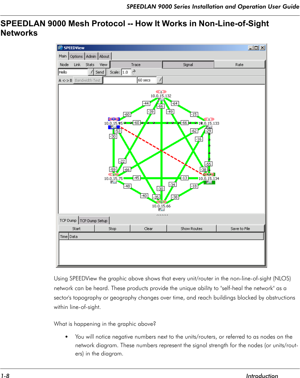
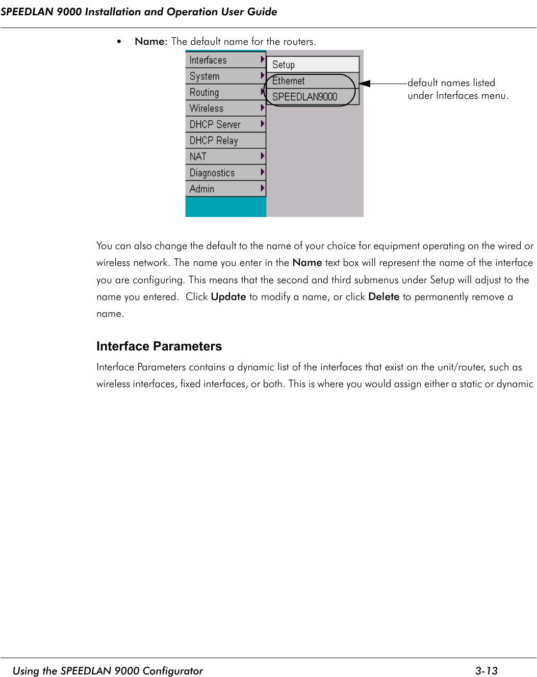
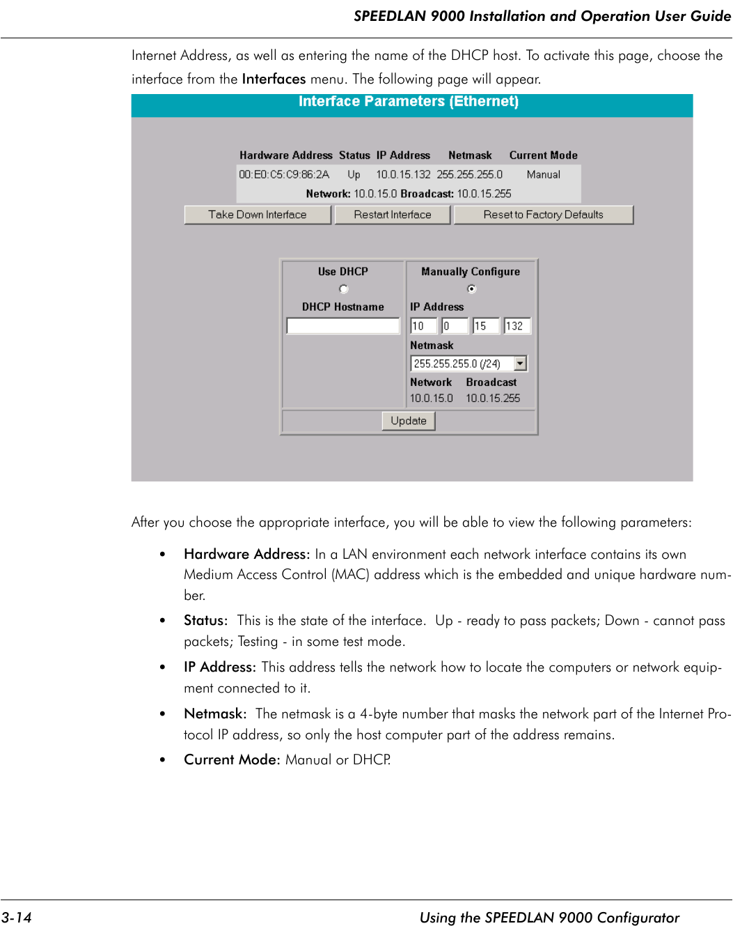
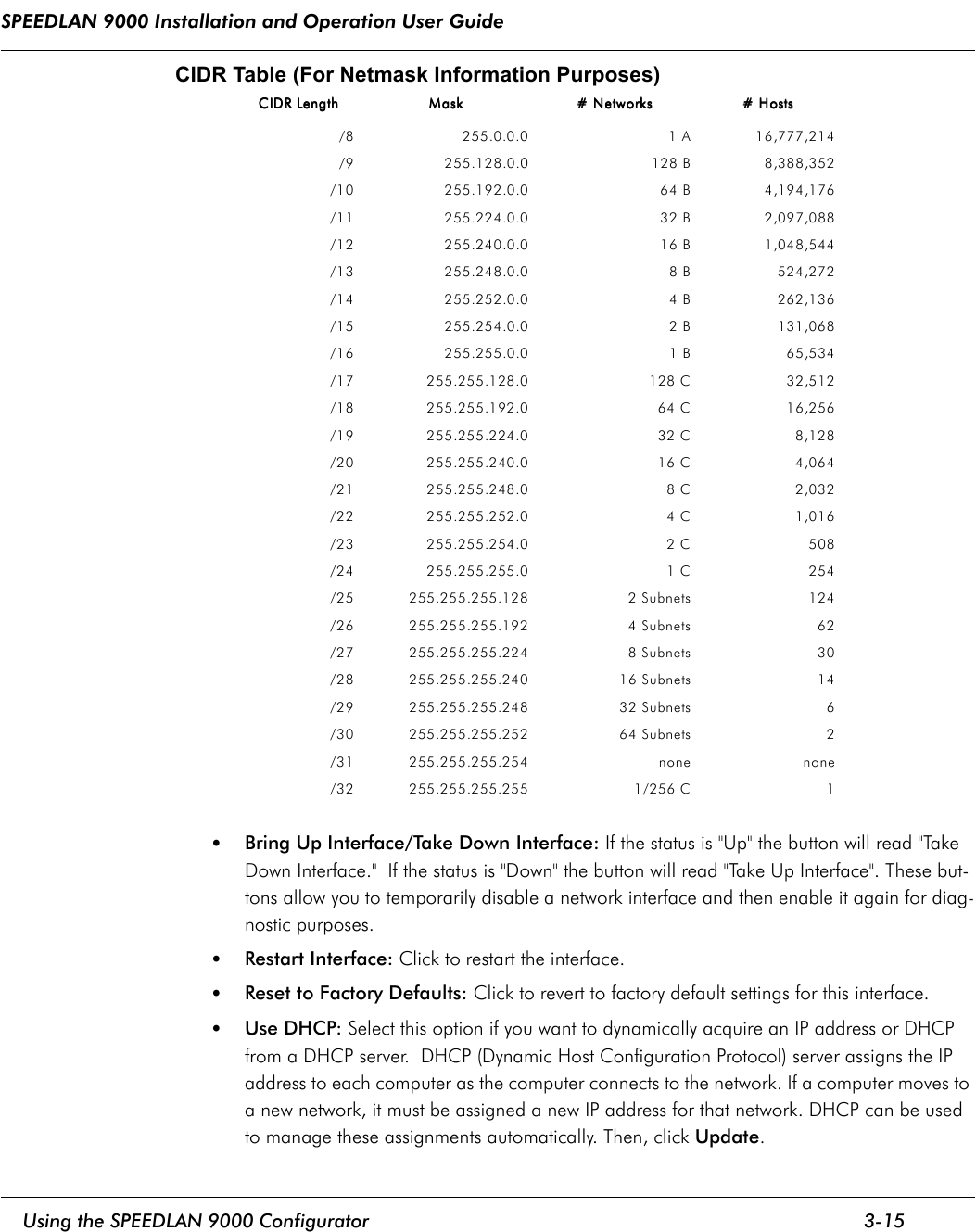
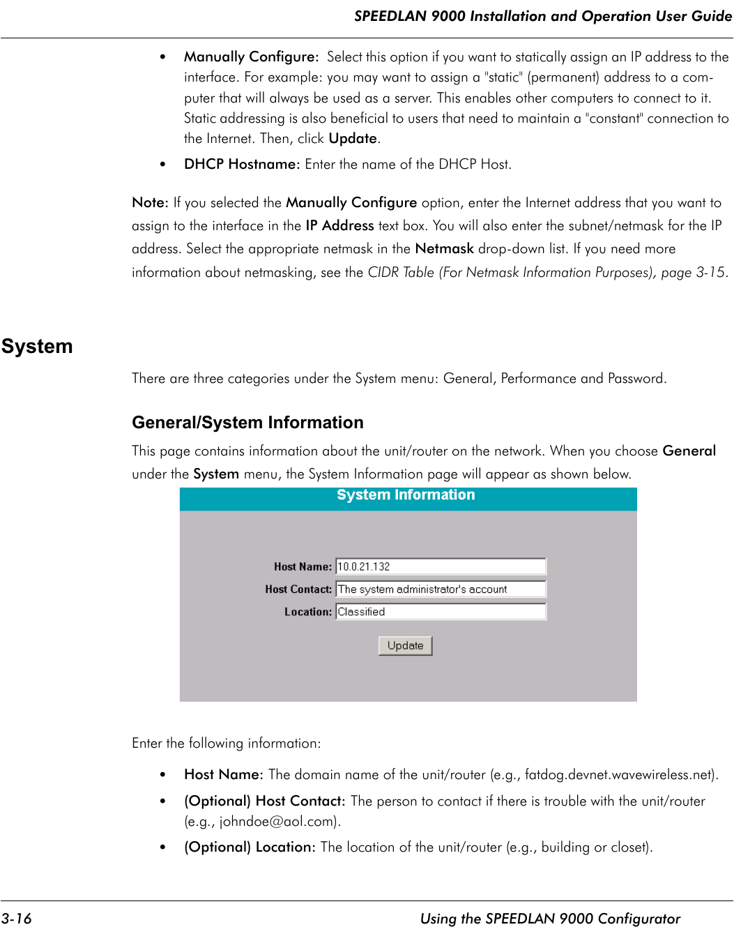
Wave Wireless Networking SL9102 Spread Spectrum Transmitter User Manual allPH900manual
Wave Wireless Networking Spread Spectrum Transmitter allPH900manual
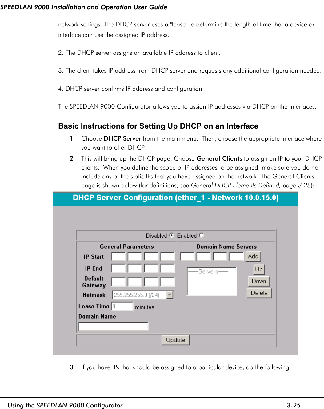
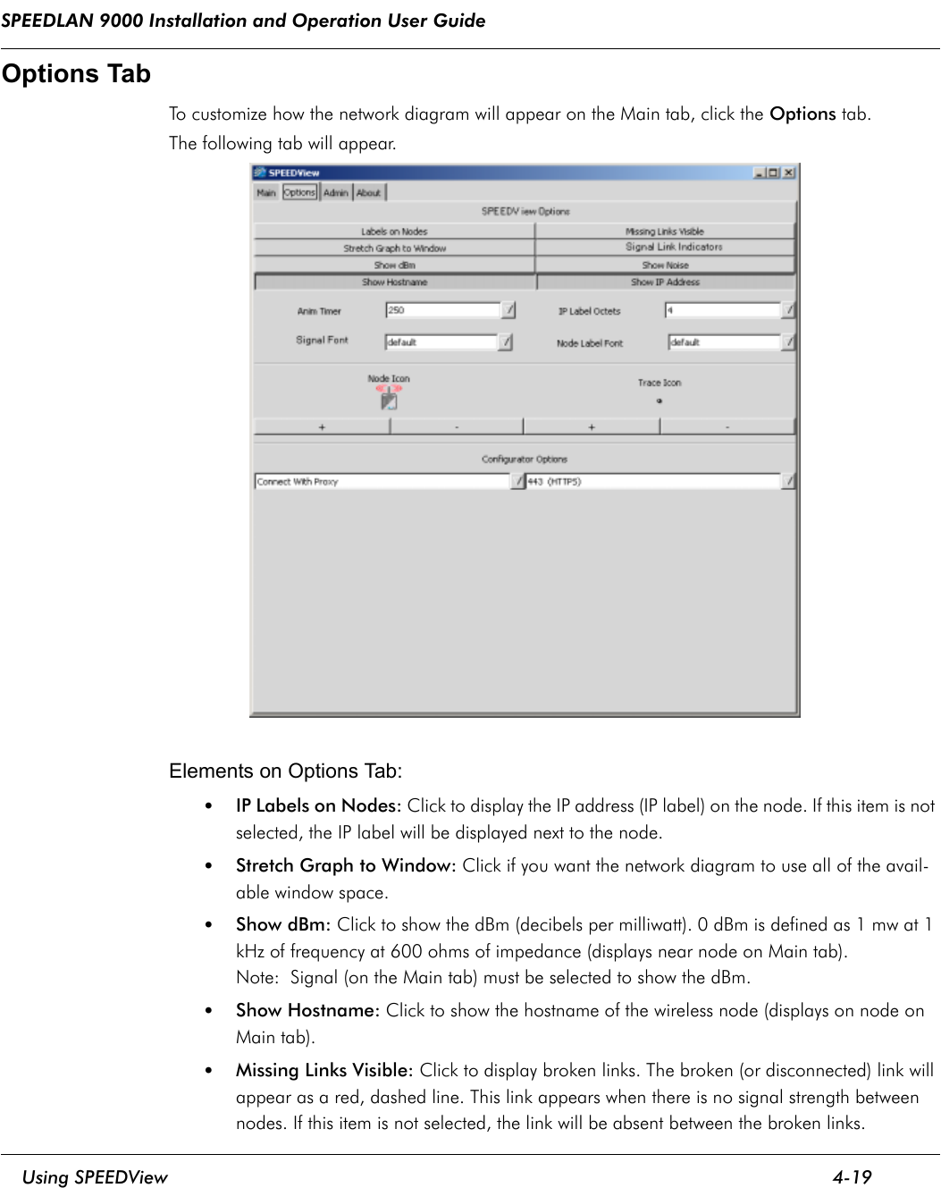
UserManual.wiki
>
Wave Wireless Networking
>
SL9102 User Manual
users manual
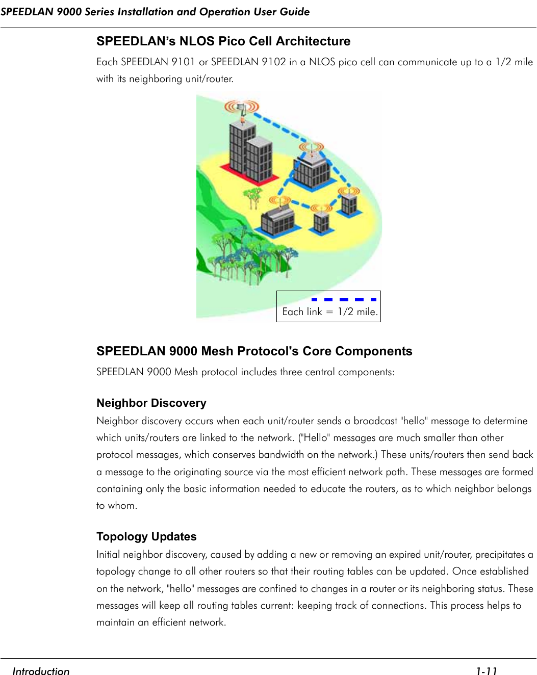
Navigation menu
Upload a User Manual
Namespaces
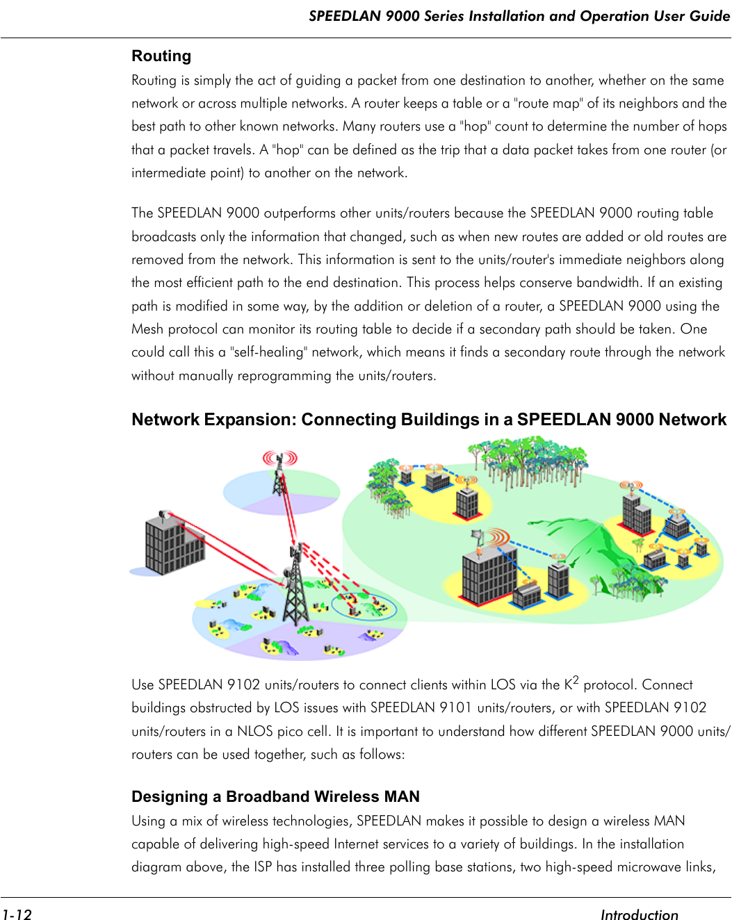
Wiki Guide
HTML
PDF
Info
Views
User Manual
Discussion / Help
Navigation