Wave Wireless 915B Wireless Modem Module User Manual
Wave Wireless Corporation Wireless Modem Module
UserManual.wiki
>
Wave Wireless
>
915B User Manual
User manual
Navigation menu
Upload a User Manual
Namespaces
Wiki Guide
HTML
PDF
Info
Views
User Manual
Discussion / Help
Navigation
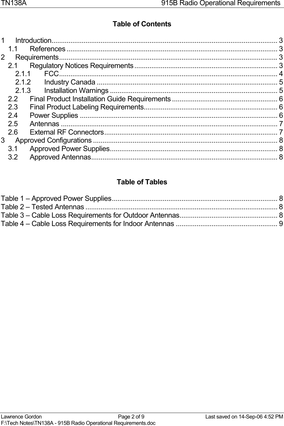
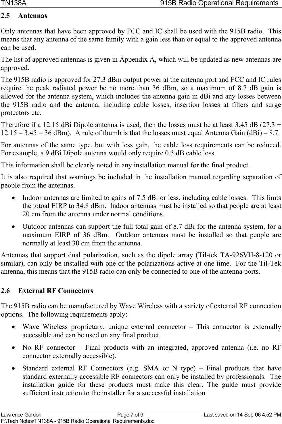
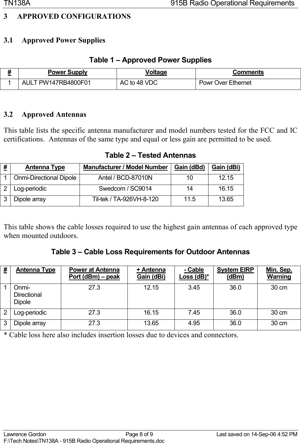
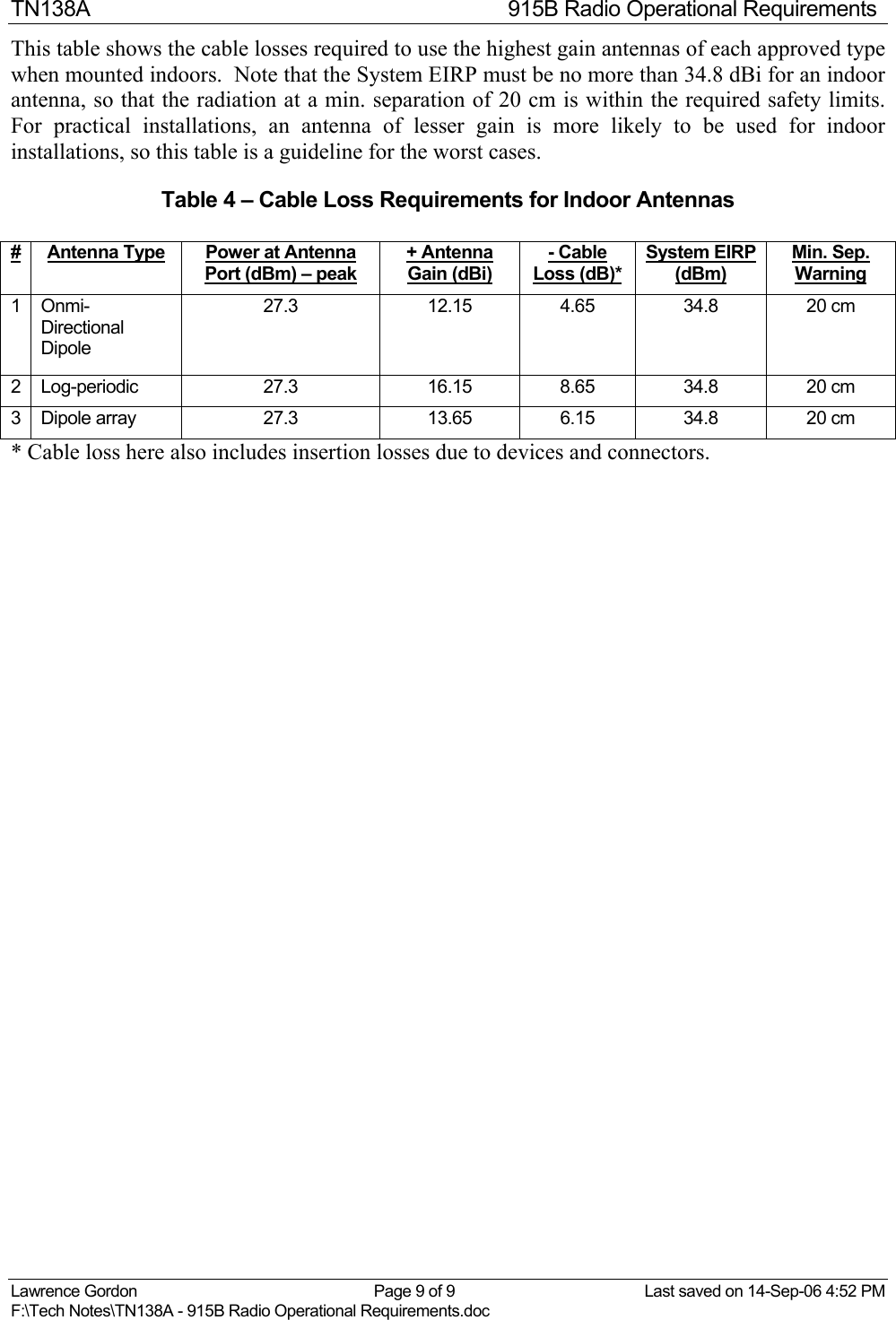
![TN138A 915B Radio Operational Requirements Lawrence Gordon Page 6 of 9 Last saved on 14-Sep-06 4:52 PM F:\Tech Notes\TN138A - 915B Radio Operational Requirements.doc 2.2 Final Product Installation Guide Requirements The regulatory notices in sections 2.1.1, 2.1.2, and 2.1.3 must be included in the installation guide for the final product edited as appropriate (e.g. use final product name rather than 915B Radio). As well, the final product installation guide must provide NO instructions on how to remove the 915B radio from the product. The following notices should be included to make this clear: This product contains no user-serviceable parts. Opening this product will void any warranty. 2.3 Final Product Labeling Requirements The final product must have a permanent label that contains the following text: “Contains FCC ID: KIN-915B” and “Contains IC: 4309B-915B”. If the label has room, then the statement “This device complies with Part 15 of FCC rules” plus the text from the Interference Environment sub-section of 2.1.1 should be included. The following picture shows the Wave Wireless standard label that is recommended for all products containing the 915B radio, edited as appropriate. CCU3100IAB0CCU3100IAB0A612624321PRODUCT:VERSION:Contains FCC ID: KIN-915BMade in Canada / Fabrique au CanadaThis device complies with Part 15 of the FCC rules.Operation is subject to the following conditions:1) This device may not cause harmful interferance and2) This device must accept any interference received, including interference that may cause undesired operation.WWW.WAVEWIRELESS.COMCOMMUNICATIONS INC.CCU3100IAB0A612624321CUSContains IC: 4309B-915B 2.4 Power Supplies The 915B radio is approved by FCC and IC using specific AC/DC converters. The currently approved converter is the AULT PW147RB4800F01 AC to 48 VDC Power over Ethernet power supply. The use of any other AC power supply requires testing to ensure it complies with FCC and IC rules on Conducted Limits on AC lines (e.g. [Part 15] 15.207). If the 915B radio is powered by a supply other than the AC lines (e.g. vehicle power) then no testing is required.](https://usermanual.wiki/Wave-Wireless/915B/User-Guide-708426-Page-6.png)