Wave Wireless AIRLINKPRO User Manual AirPro Manual 64
Wave Wireless Corporation AirPro Manual 64
UserManual.wiki
>
Wave Wireless
>
AIRLINKPRO User Manual
AirPro Manual 64
Navigation menu
Upload a User Manual
Namespaces
Wiki Guide
HTML
PDF
Info
Views
User Manual
Discussion / Help
Navigation
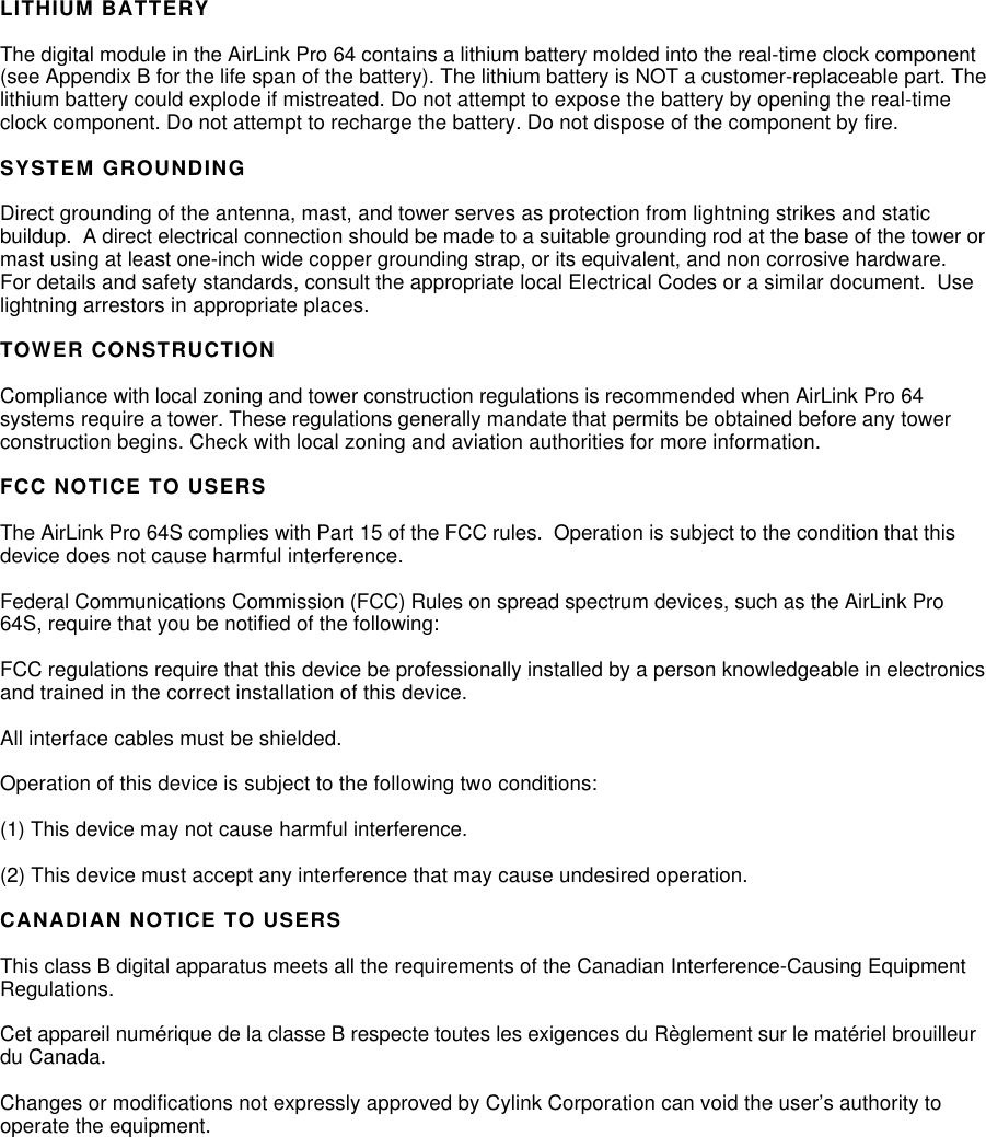

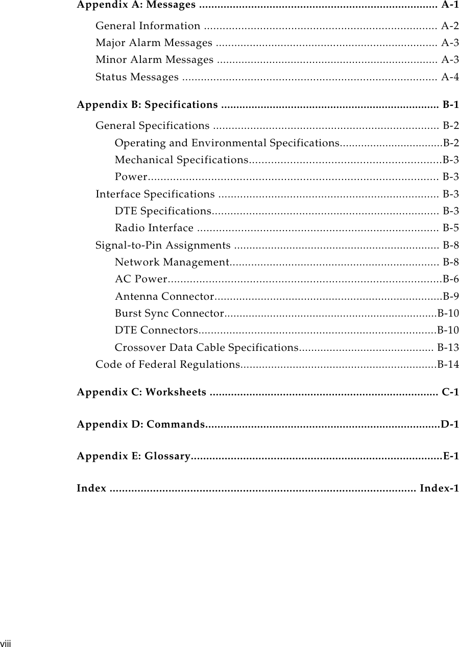

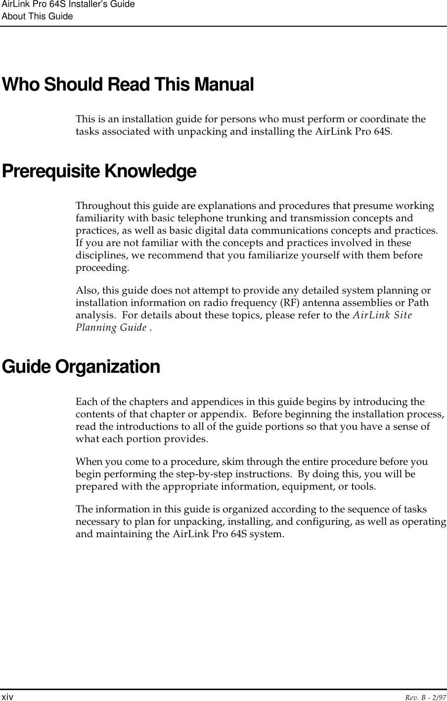
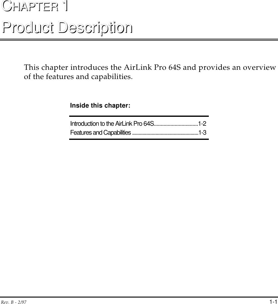
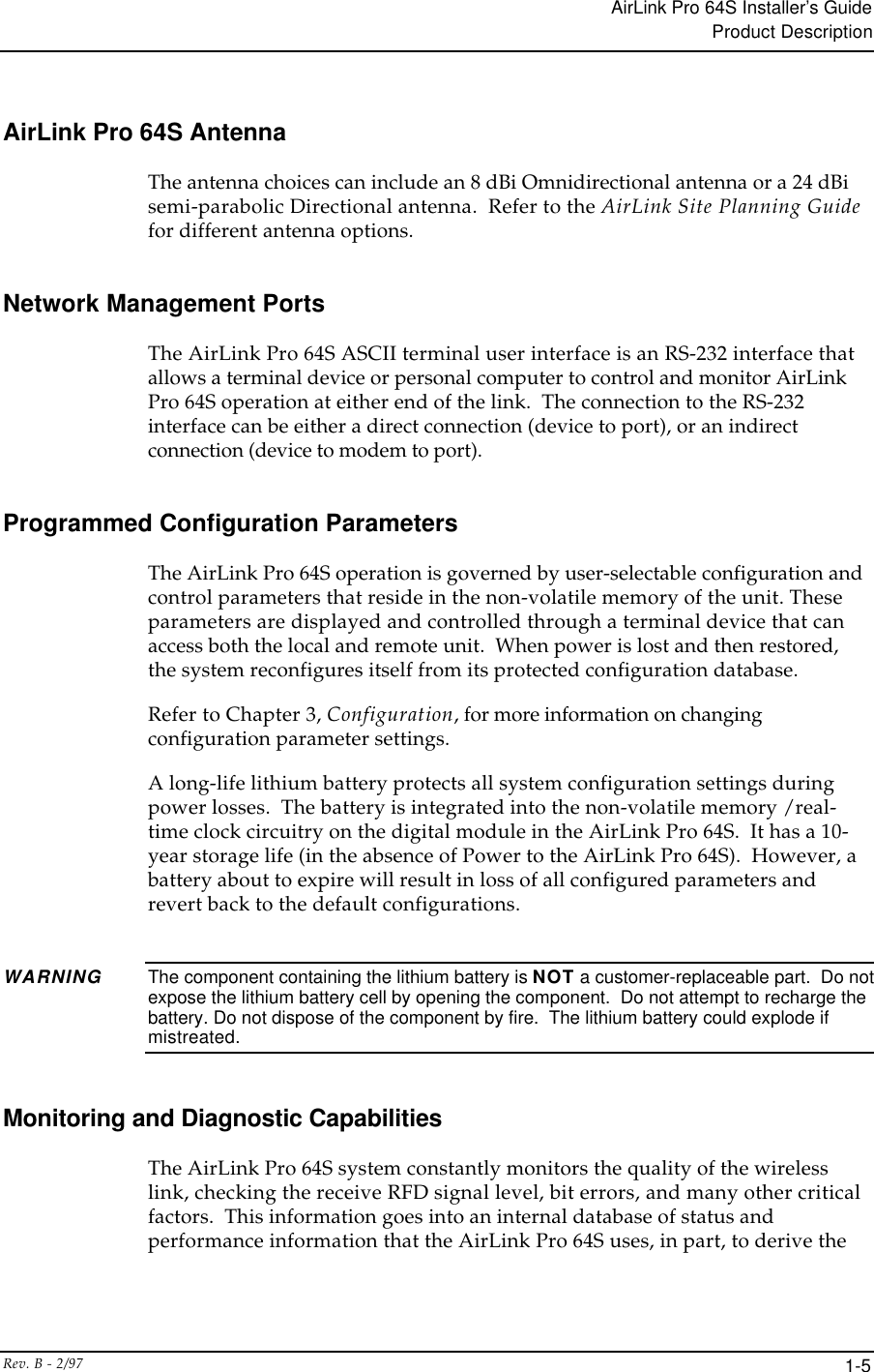
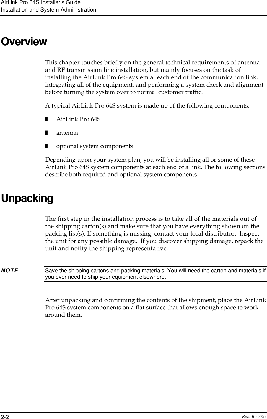
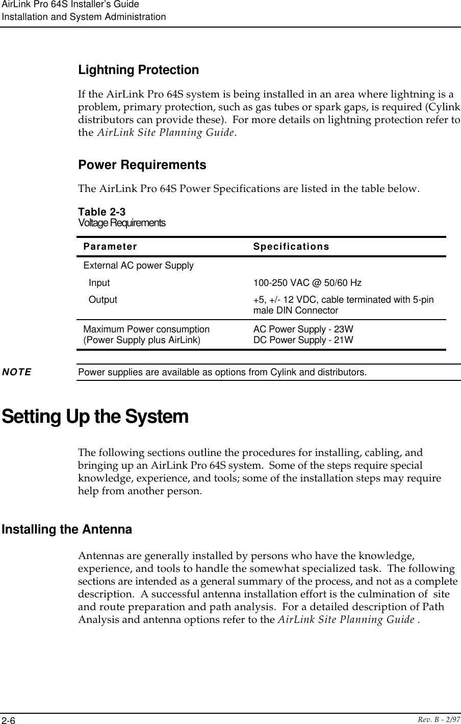
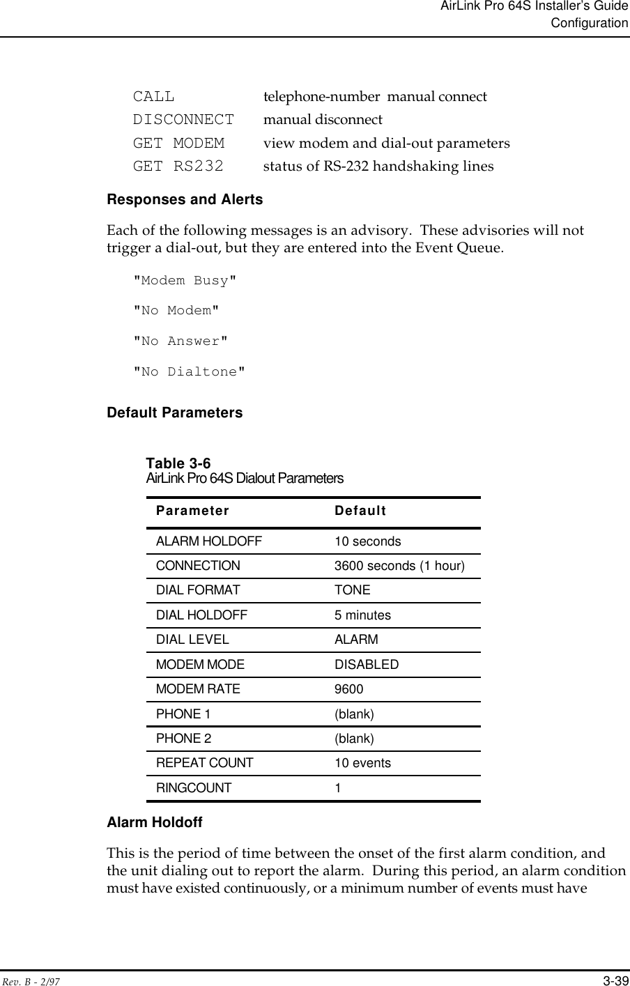
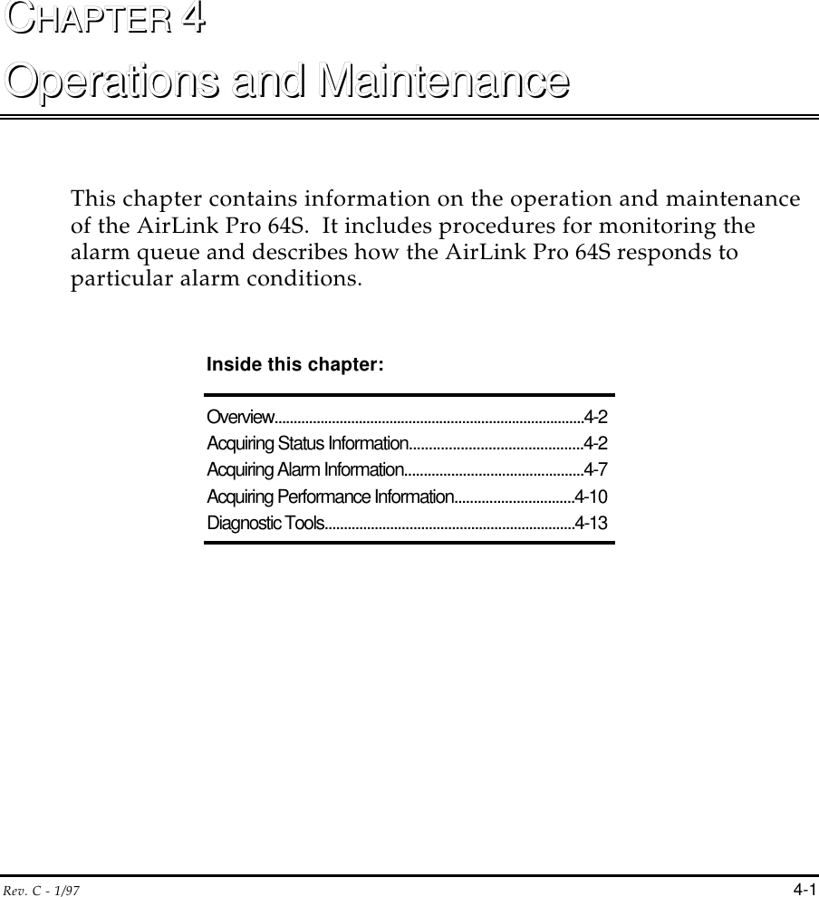
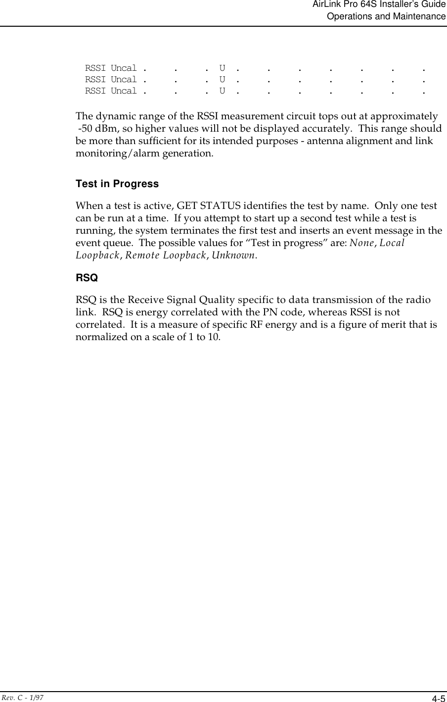
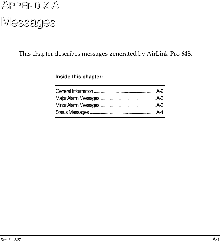
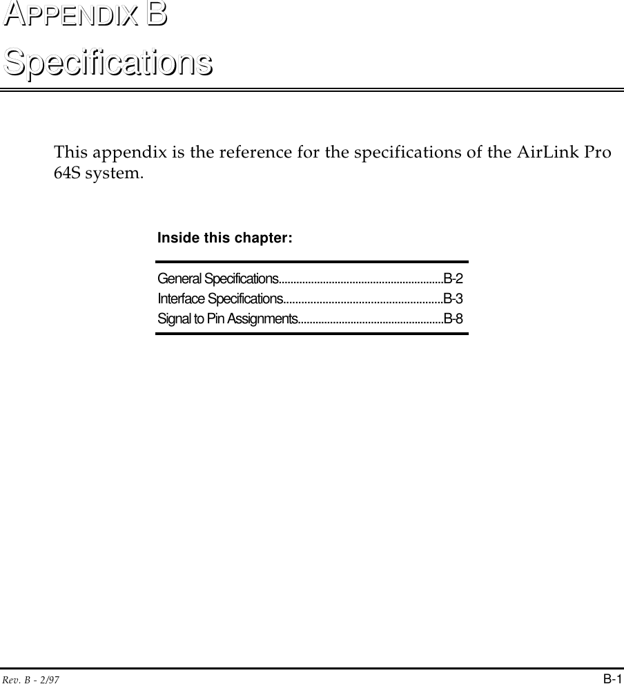
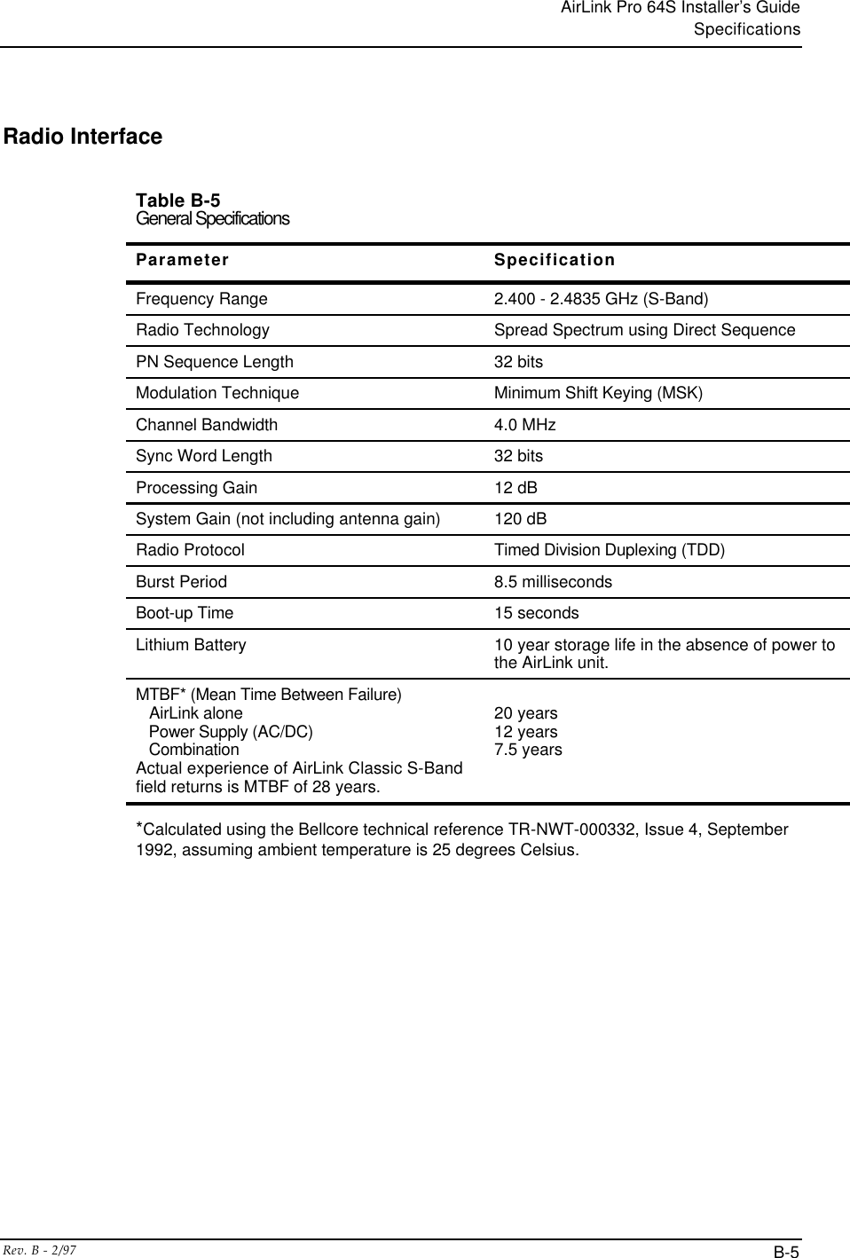
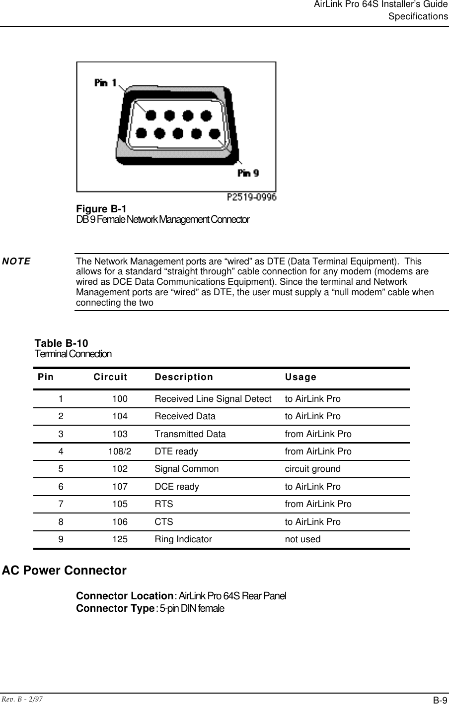
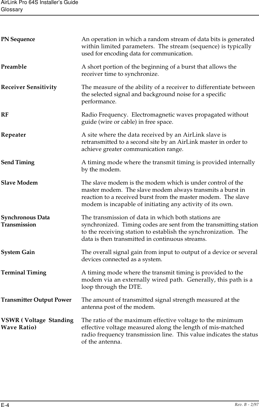
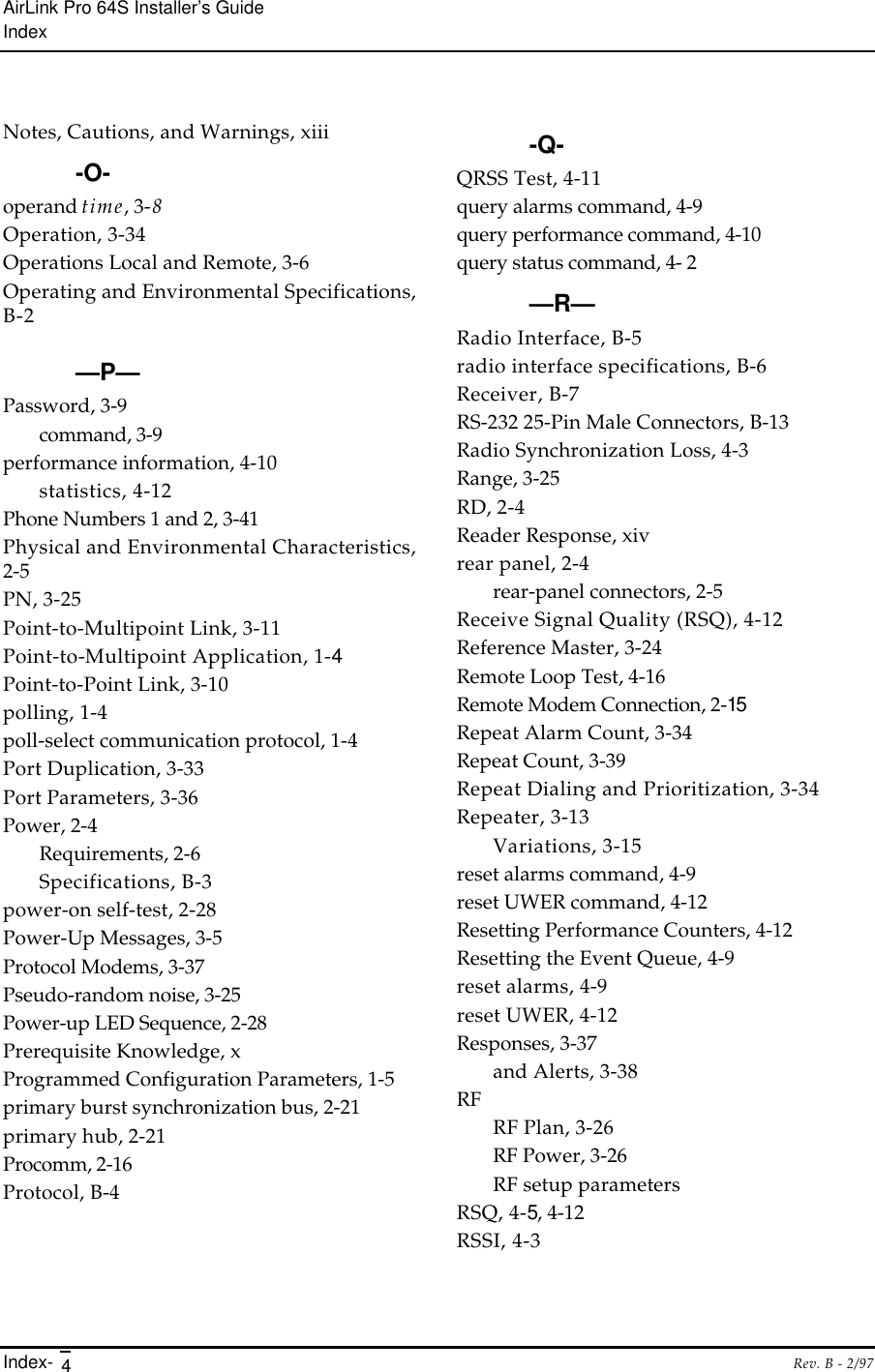
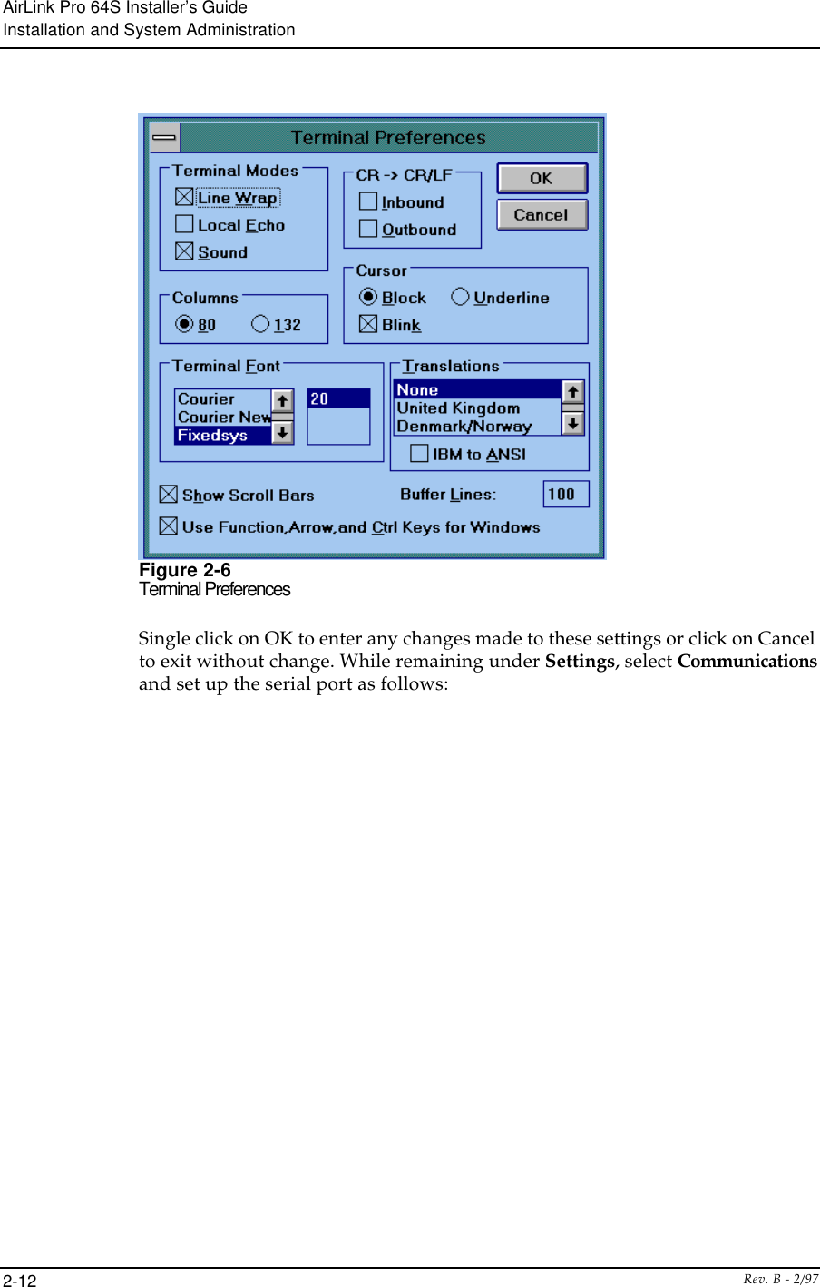
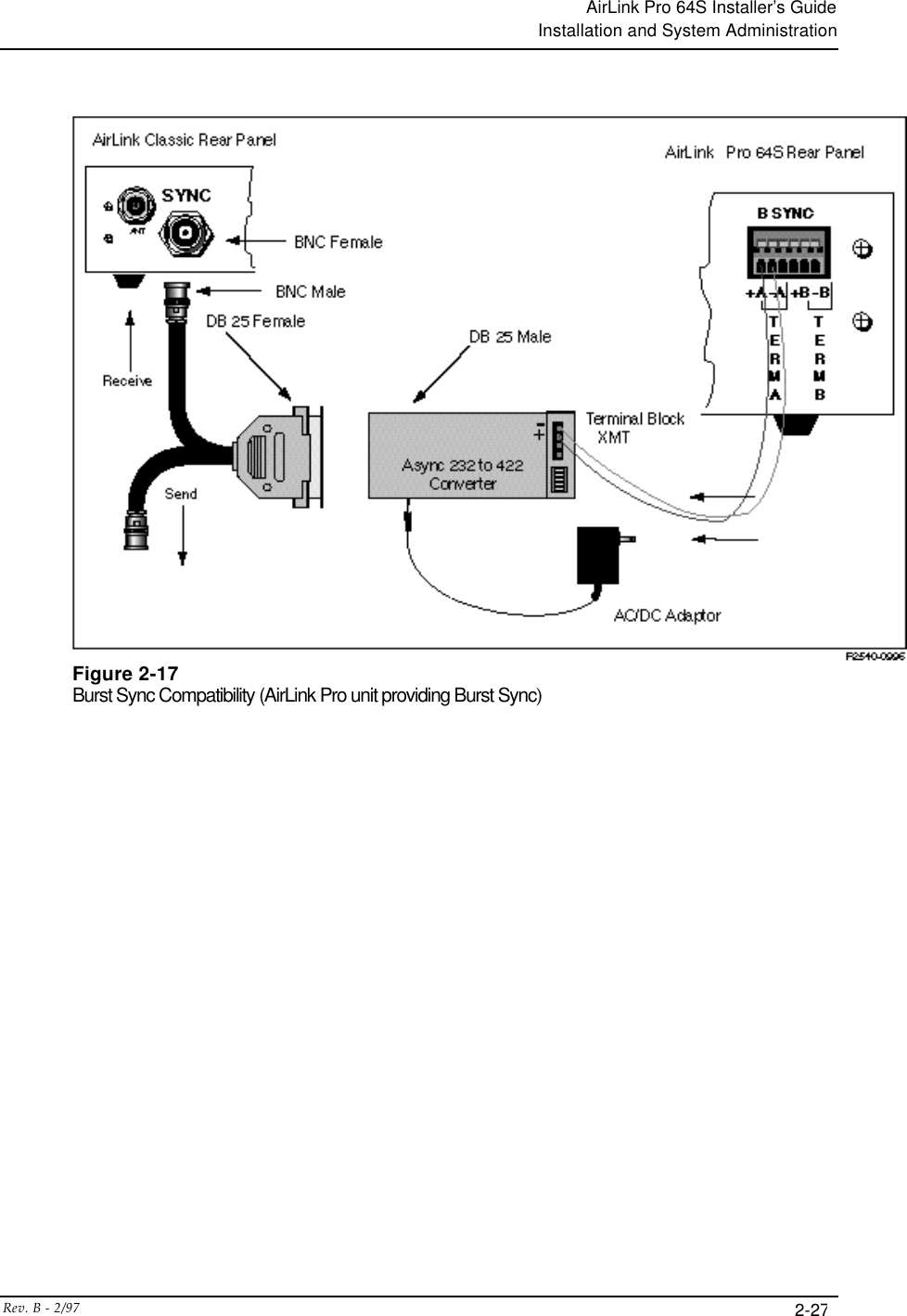
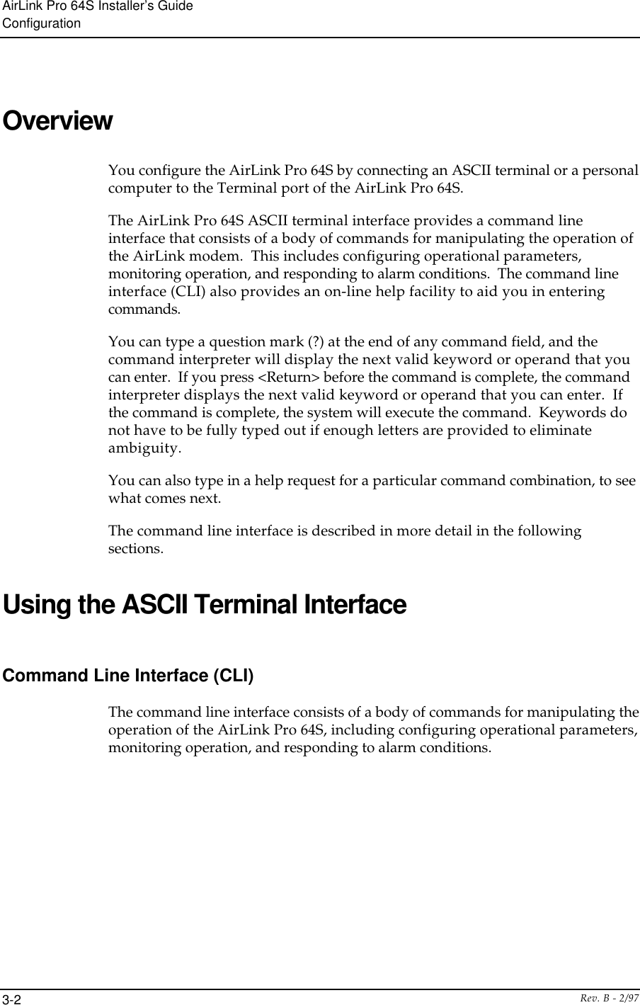
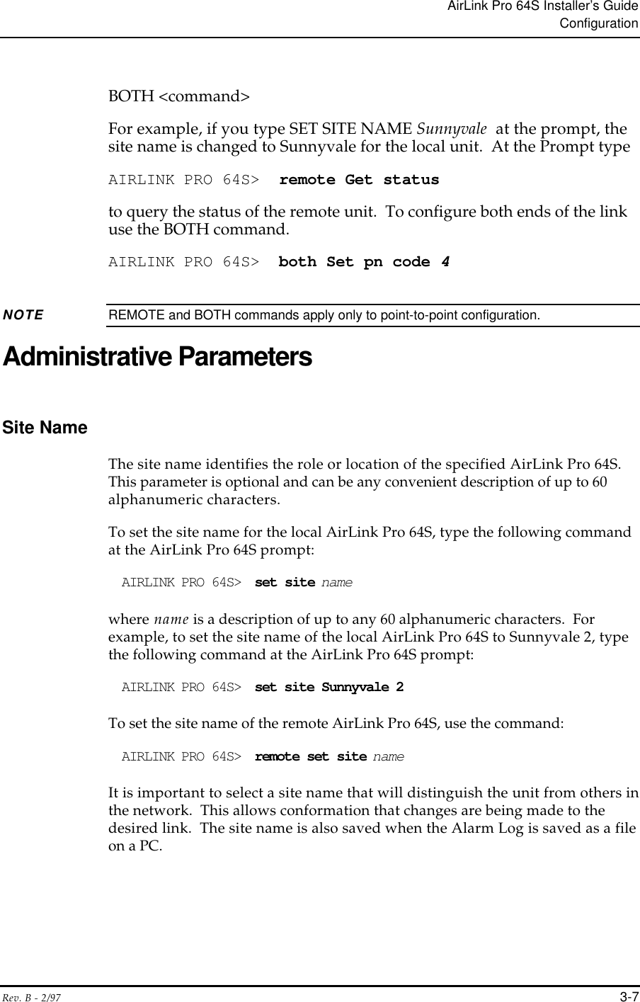
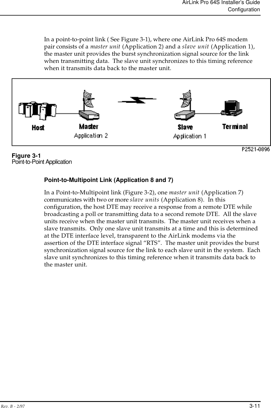
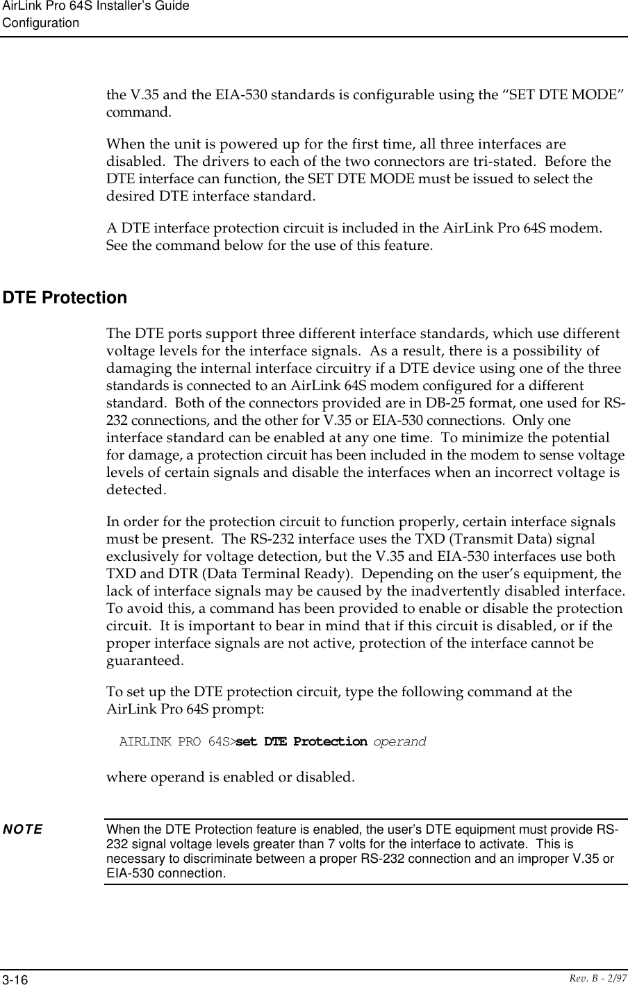
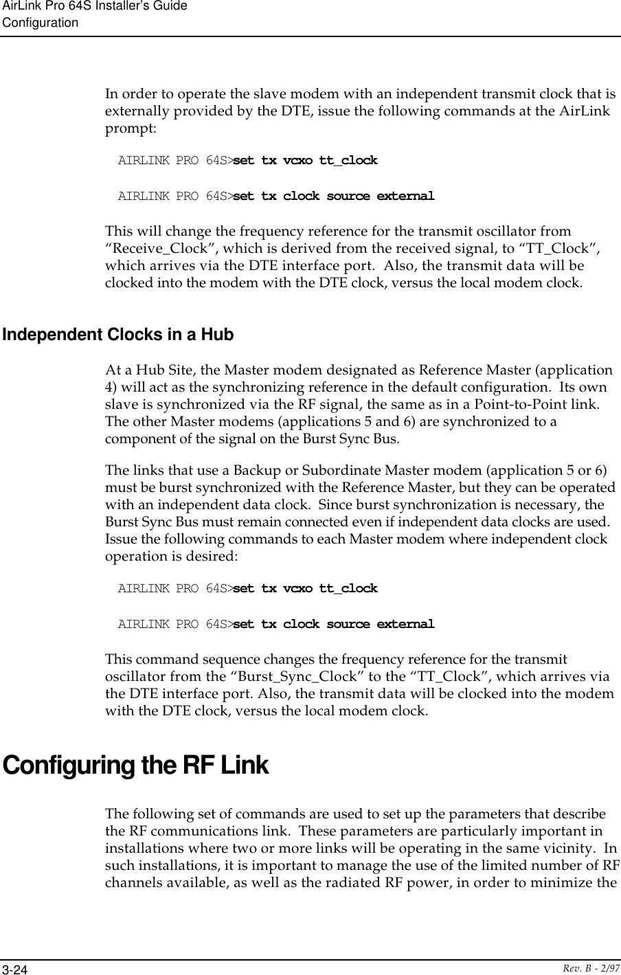
![AirLink Pro 64S Installer’s GuideInstallation and System AdministrationRev. B - 2/97 2-11Pressing <Break> at the terminal puts the AirLink Pro 64S terminal interfacesoftware in “hunt” mode, where it looks for carriage return (<Return>)characters from the attached terminal. If the terminal is set for 19200, 9600,4800, 2400, or 1200 bps, the terminal interface software learns the operatingbaud rate by starting at 19200 bps and dropping to the next lower speed in thesequence for each press of the <RETURN> key until it recognizes a <Return>character. When the software detects a <Return> character, it displays theAirLink Pro command-line prompt:AIRLINK PRO 64S>NOTE Lap top computers do not support the break function.Pressing <Break> puts the terminal interface software back into hunt mode. Ifthe prompt does not appear, press <Break>once, then press <Return>repeatedly at one second intervals until the AirLink Pro 64S prompt appears. Ifthe prompt doesn’t appear after pressing <Return> six times, press <Break>and try again.Terminal Setup Requirements (for personel computers with Windows™)A personal or laptop computer can be used as a dummy terminal to configure,status, and acquire information from the AirLink Pro 64S radio. The serialcommunication port (com1 or com2) of the computer must be connected to either ofthe two Network Management Ports on the rear panel of the unit. There areother communication software packages like Procomm™ that can be used toemulate a dummy terminal. The instructions given below are a guide to usingthe Microsoft Windows terminal emulation software.Using the mouse buttons double click on the ACCESSORIES icon under theProgram Manager of Windows. Double click on the TERMINAL icon. Pull downthe menu under Settings near the top of the screen, and single click on TerminalEmulation. Select DEC VT-100 [ANSI] (see Figure 2-4 ) then single click on OK.Figure 2-5Terminal EmulationNow go back to settings and single click on Terminal Preferences, and set up theterminal parameter as follows:](https://usermanual.wiki/Wave-Wireless/AIRLINKPRO/User-Guide-29583-Page-34.png)
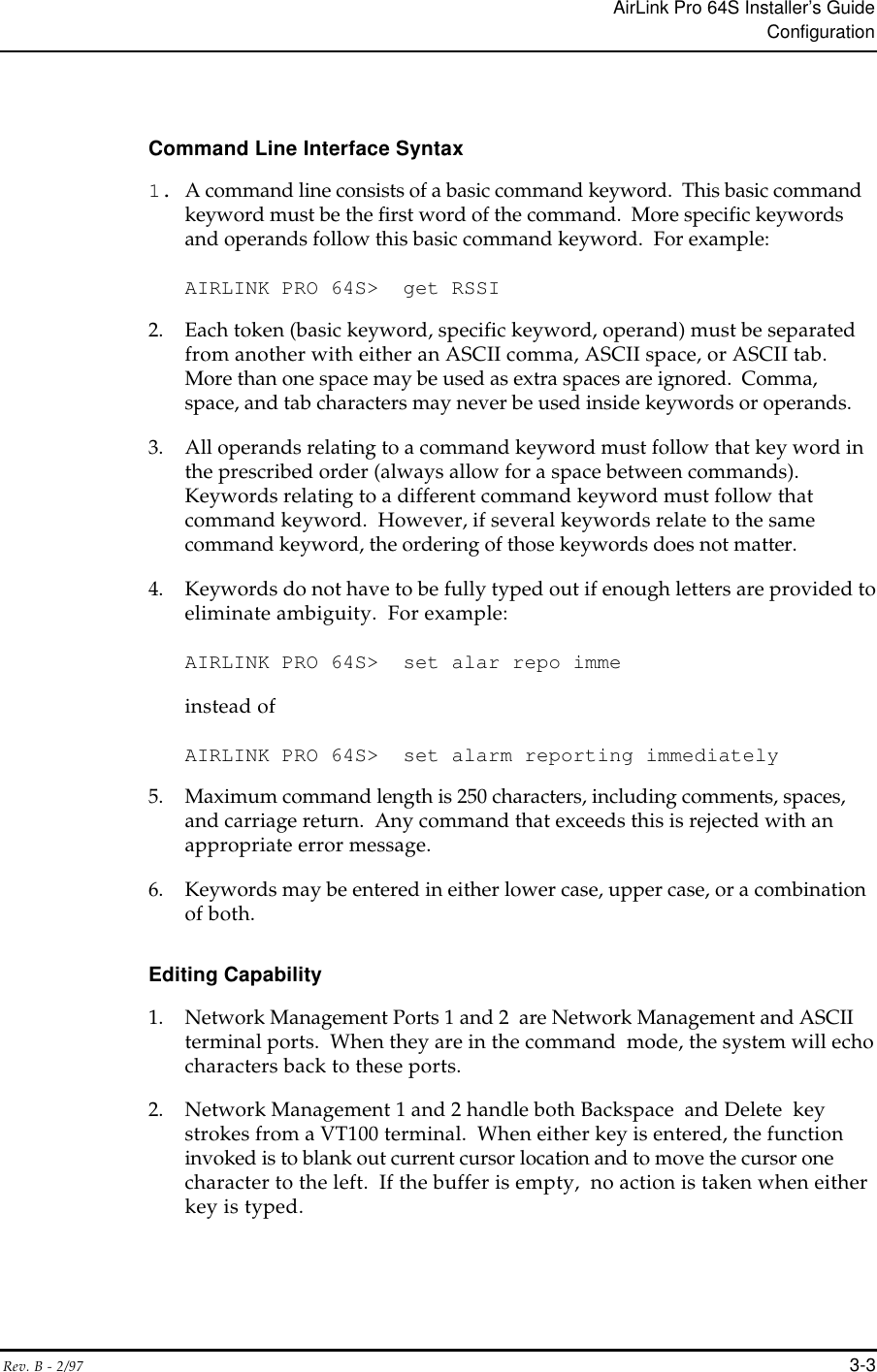
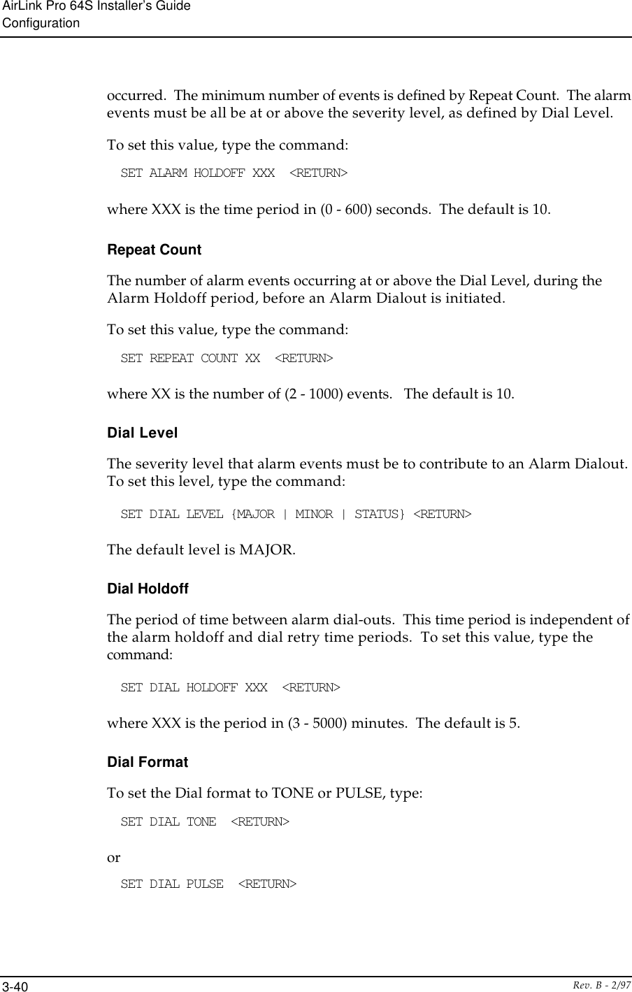
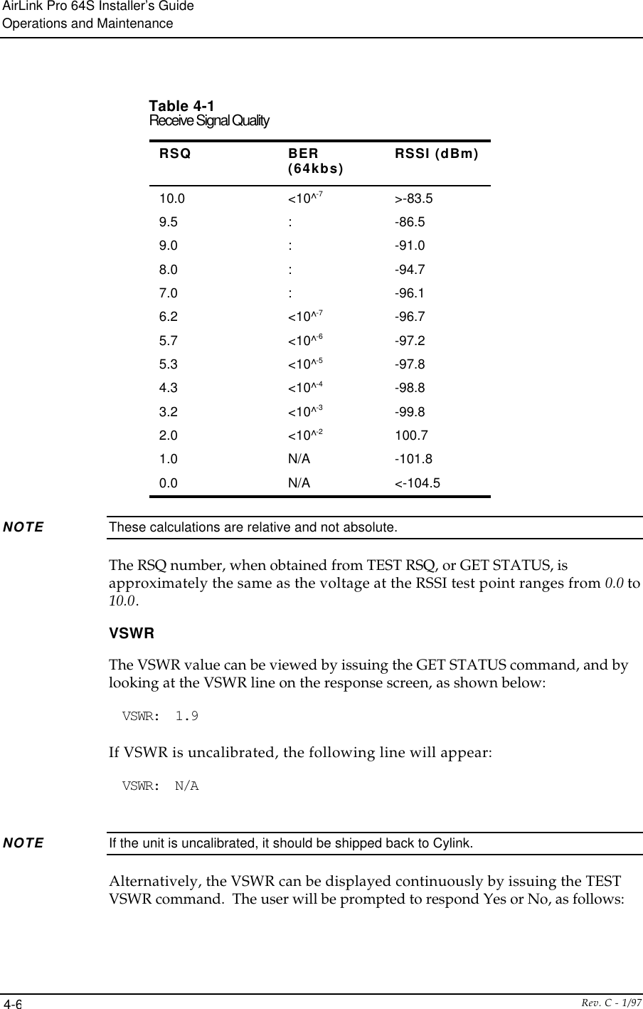
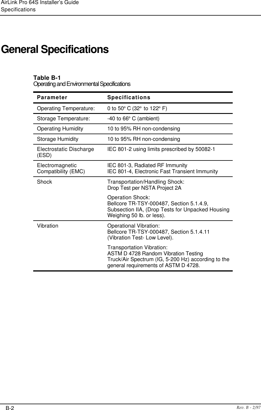
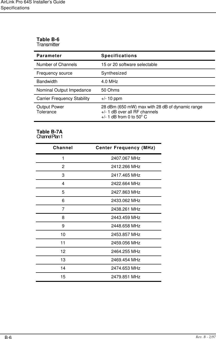
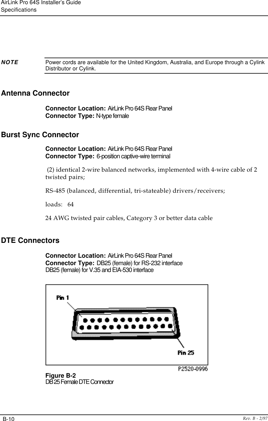
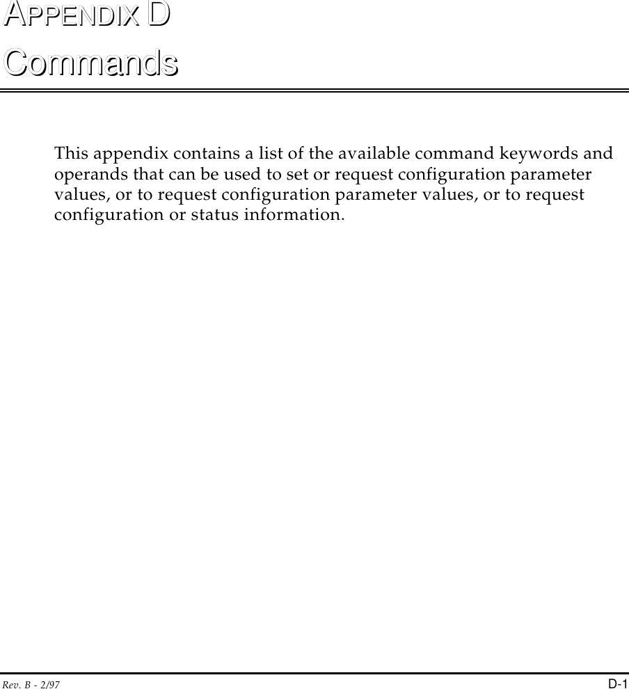
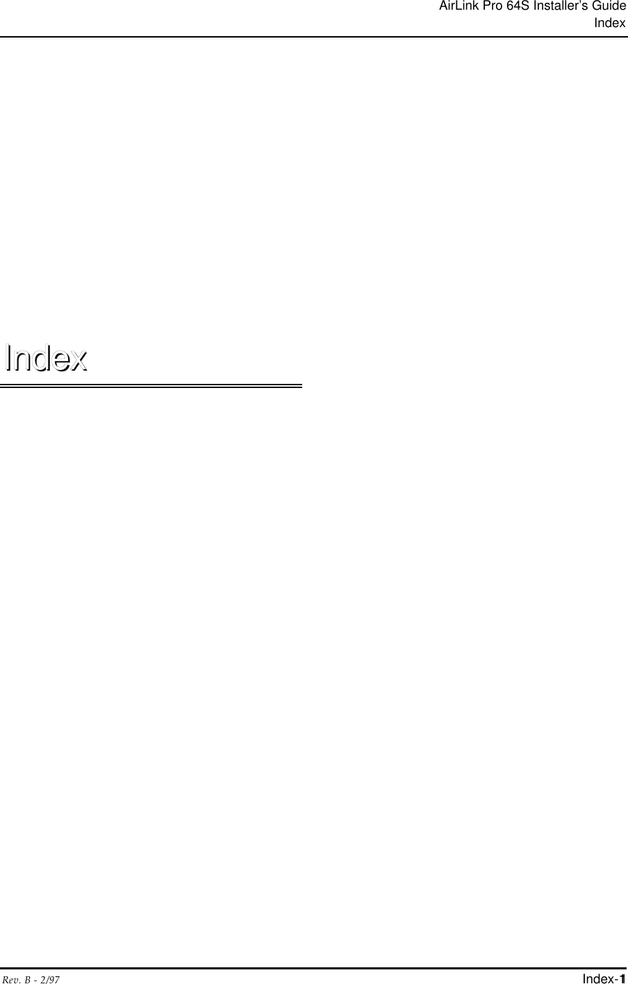
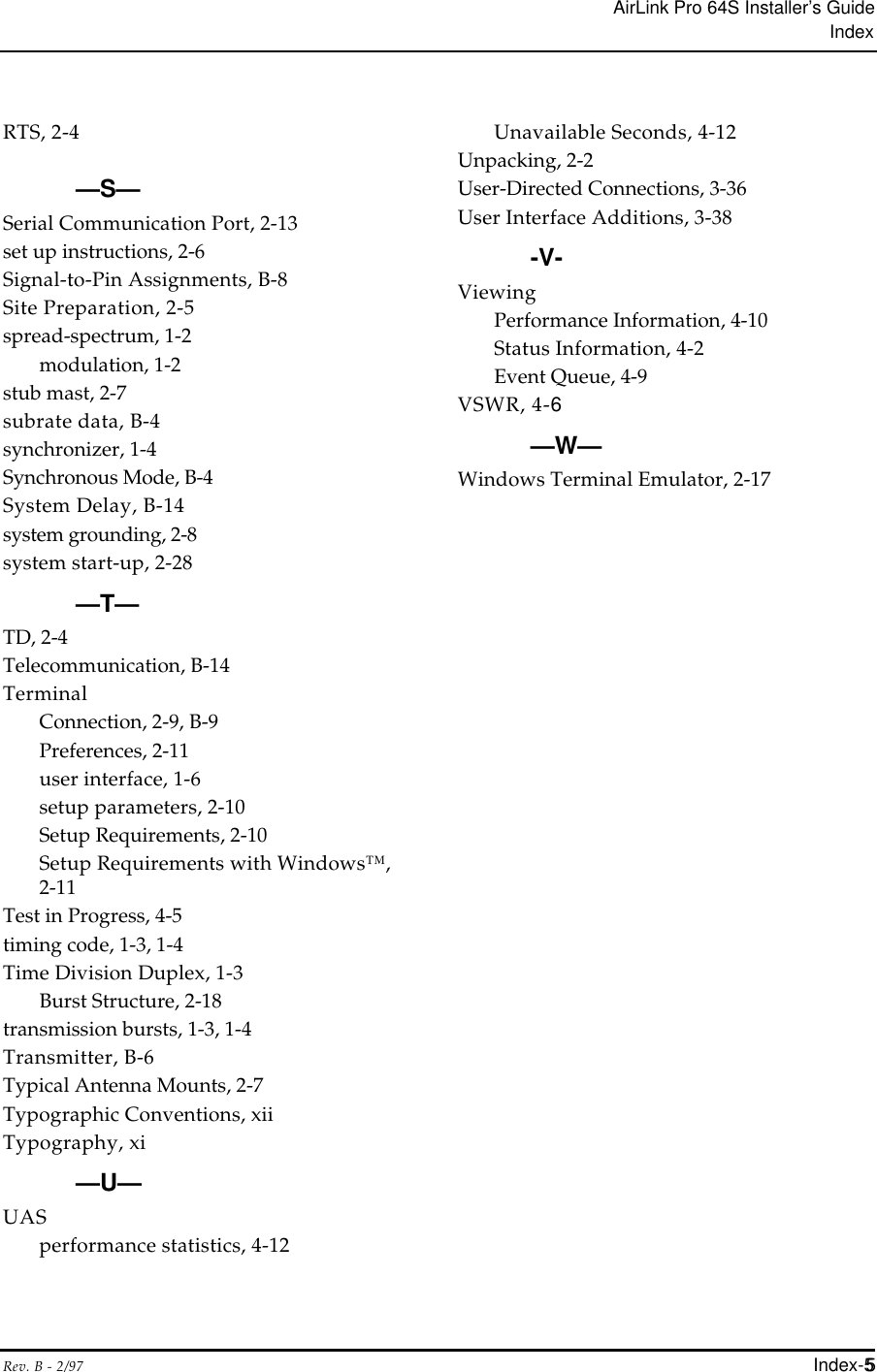
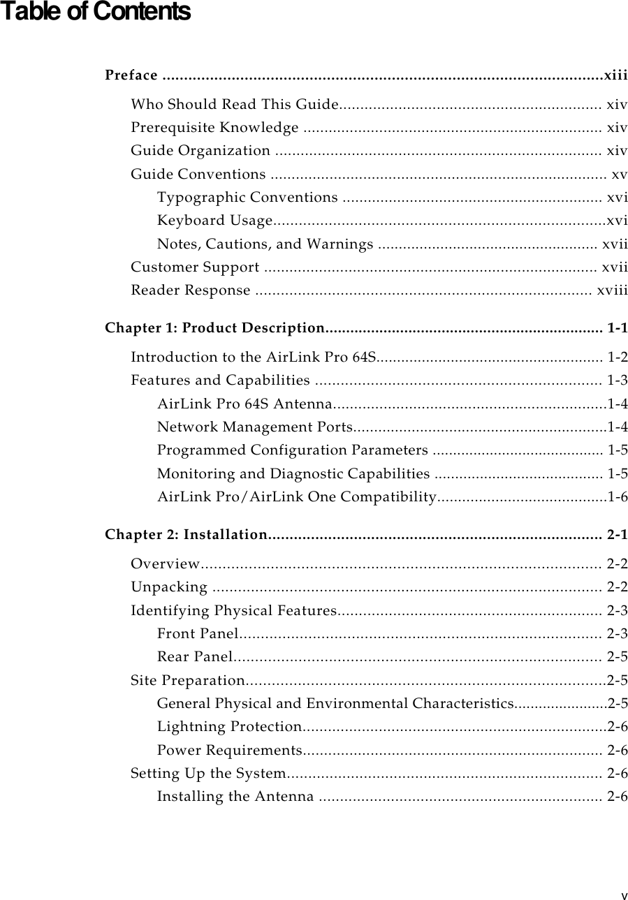
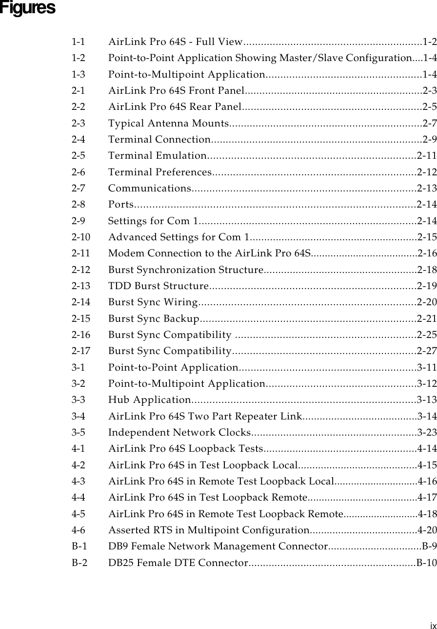
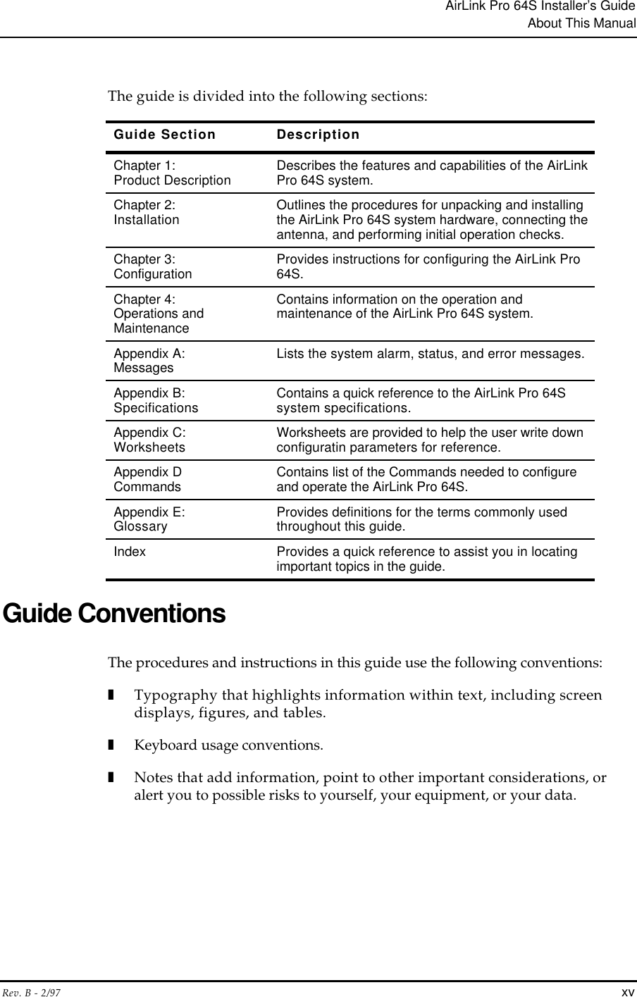
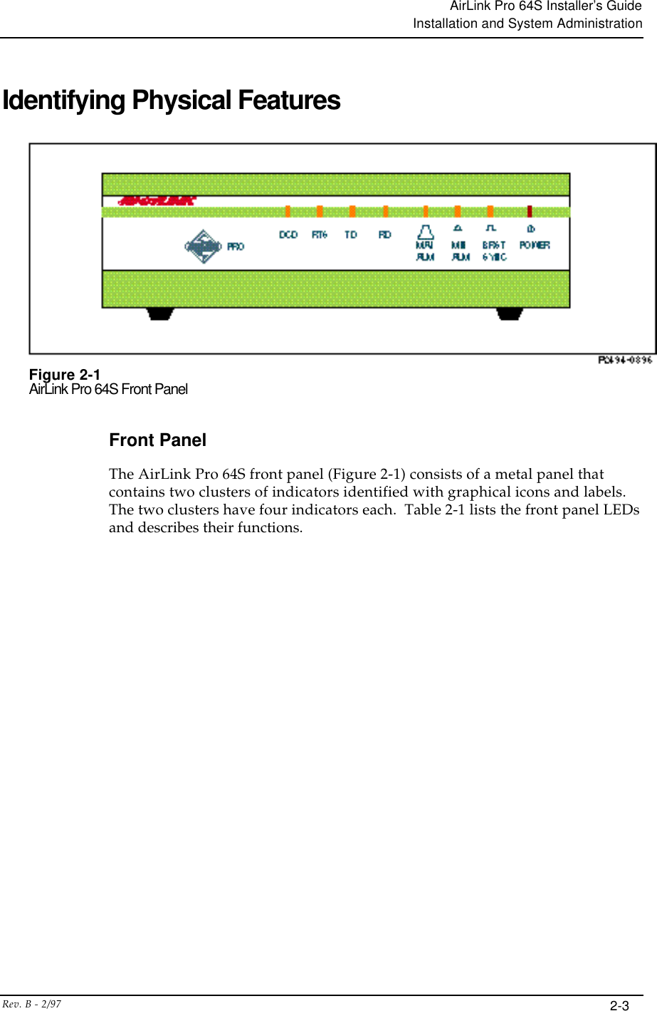
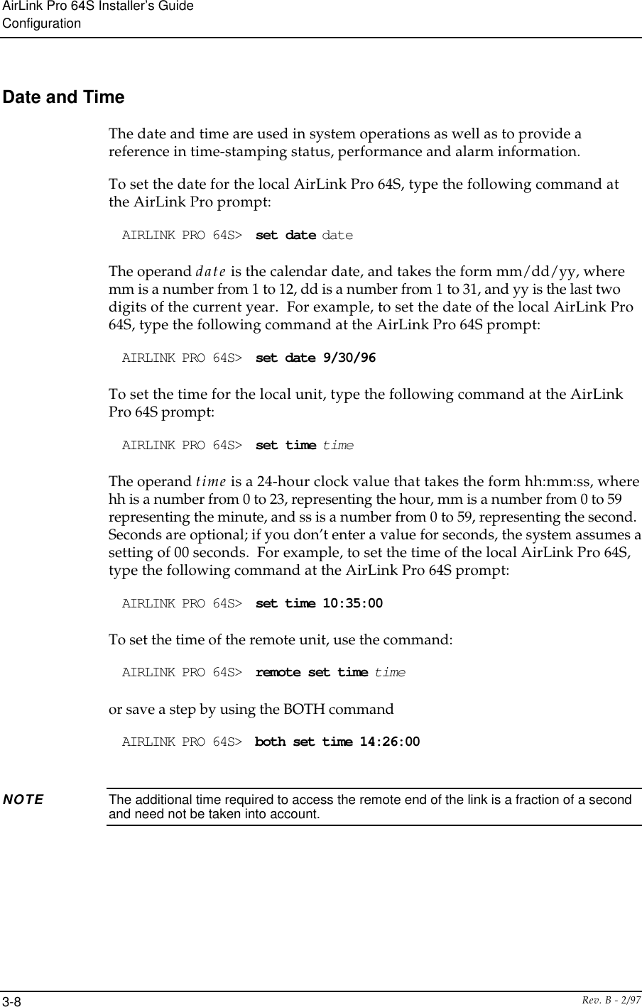
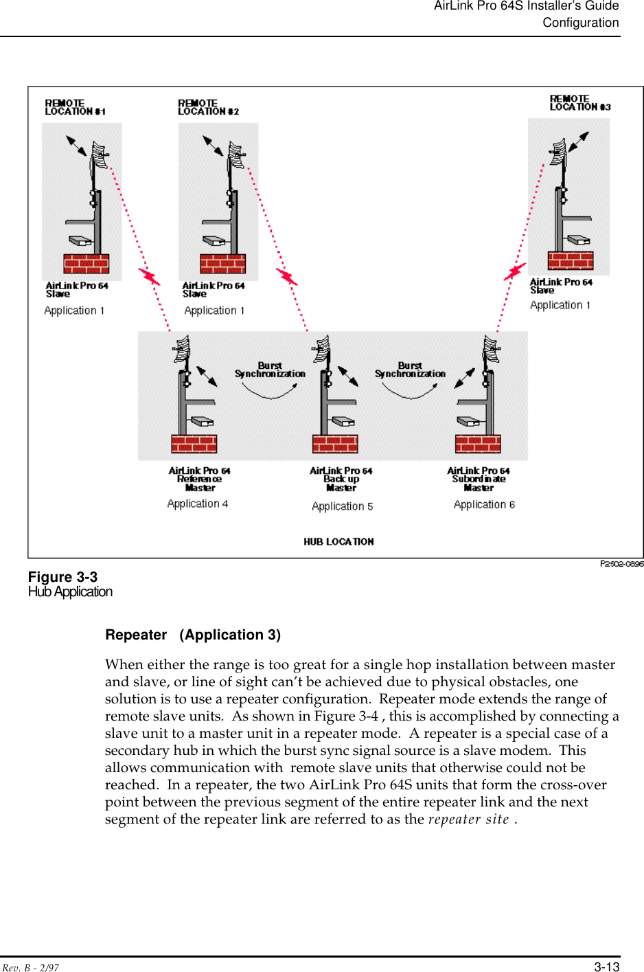
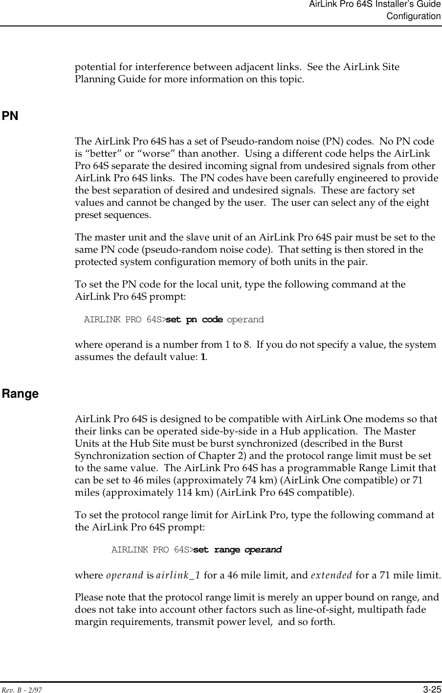
![AirLink Pro 64S Installer’s GuideConfigurationRev. B - 2/973-43. When the escape key <Esc> is struck during the typing of a command line,all characters typed are deleted, and the system is then ready to acceptanother command.4. When <Control> R is pressed, at the prompt, the previously issuedcommand is displayed. This command can be edited by backspacing todelete characters from the end, and/or by augmenting the command withadditional characters. This is particularly helpful when the user types anincomplete command; all the user needs to type is the remaining word(s).5. A limited help facility is available for the command mode. In commandline, the user may type a question mark ( ? ) at a position where a keywordshould be entered. The Controller displays the available keywords alongwith their explanation. When the user types a question mark at a positionwhere an operand should be entered, the Controller displays the availableoperands and their input range (for instance, 1 to 30, or Yes, No) along withthe explanation of the operands. After printing the help text, theController reprints the command that the user typed without the questionmark and gets ready for the user to type the next operand.6. The same help facility described above is provided when the user enters acarriage return instead of a question mark before the end of a command.There is a difference in response between the termination with a carriagereturn and termination with a question mark. When a question mark isentered, the system always prints the help text for the next token. When acarriage return is entered, the help text is displayed only if the command isnot properly terminated. Otherwise, the system treats it as a completecommand and continues with execution.Command and Operand Description Syntax1. A description syntax is used to show operand ranges and keyword choices.This syntax is used for description purposes only and not for the commanditself.2. [ x1 | x2 | ... | xn] indicates that one of the elements in the set may beselected.3. “ - “ ( a hyphen) indicates a range of numbers explicitly put into thecommand.Command Keyword ListCommand keywords and operands can be used to set or requestconfiguration parameter values, or status information. For keywordslonger than four letters, only the first four letters of each keyword arenecessary and case is not checked (all strings are converted to uppercase). White space characters are required between keywords but the](https://usermanual.wiki/Wave-Wireless/AIRLINKPRO/User-Guide-29583-Page-60.png)
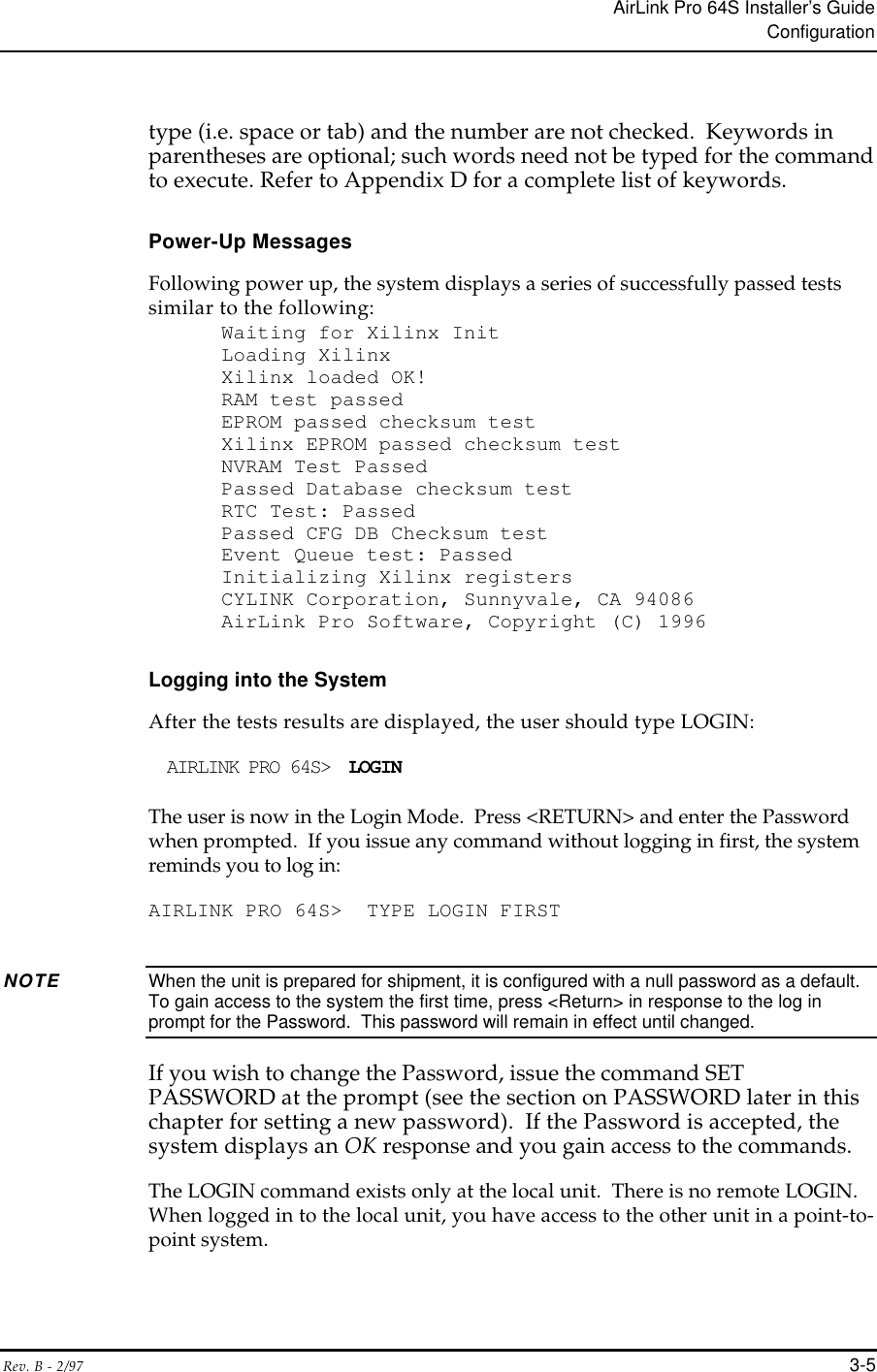
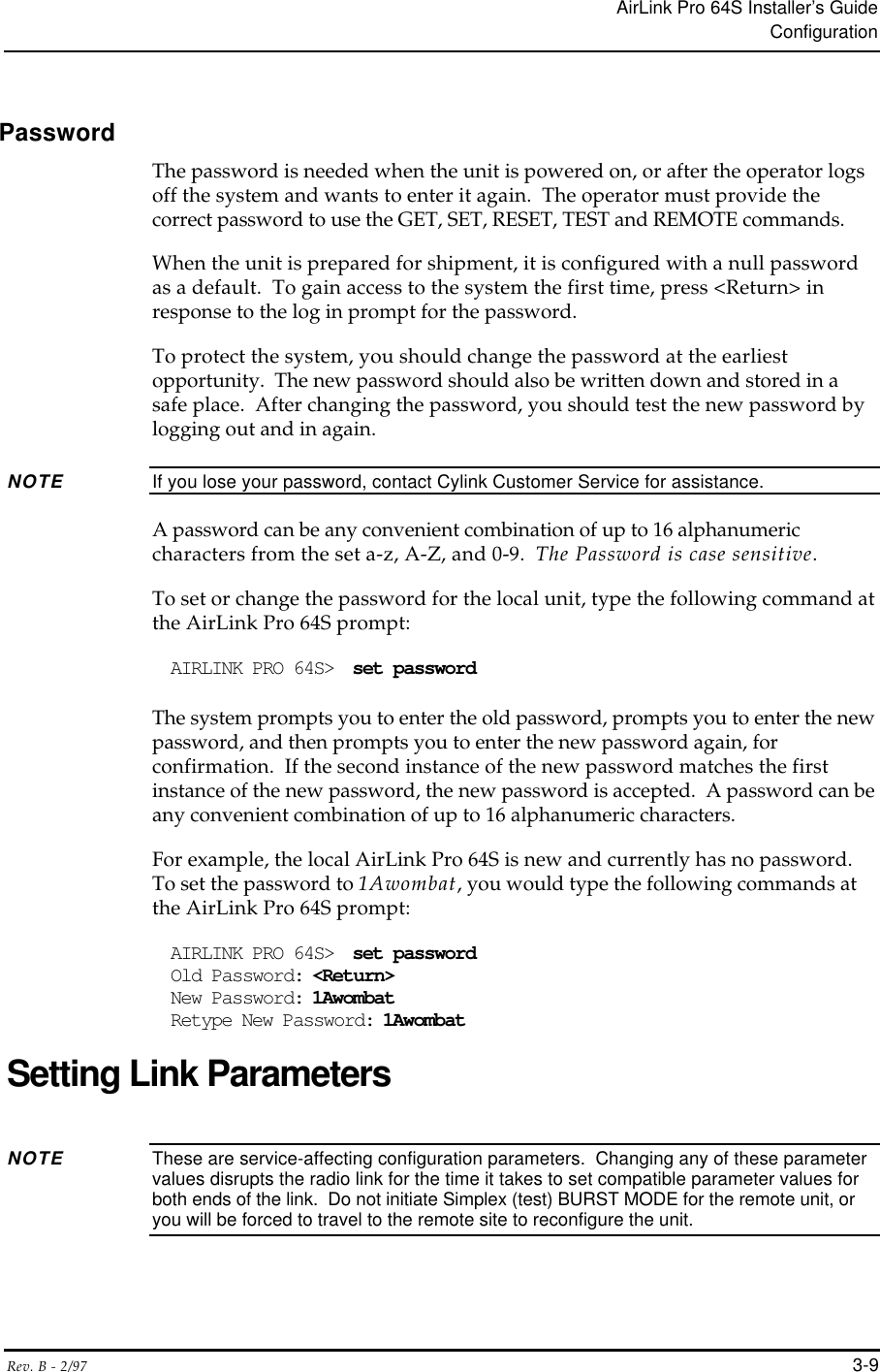
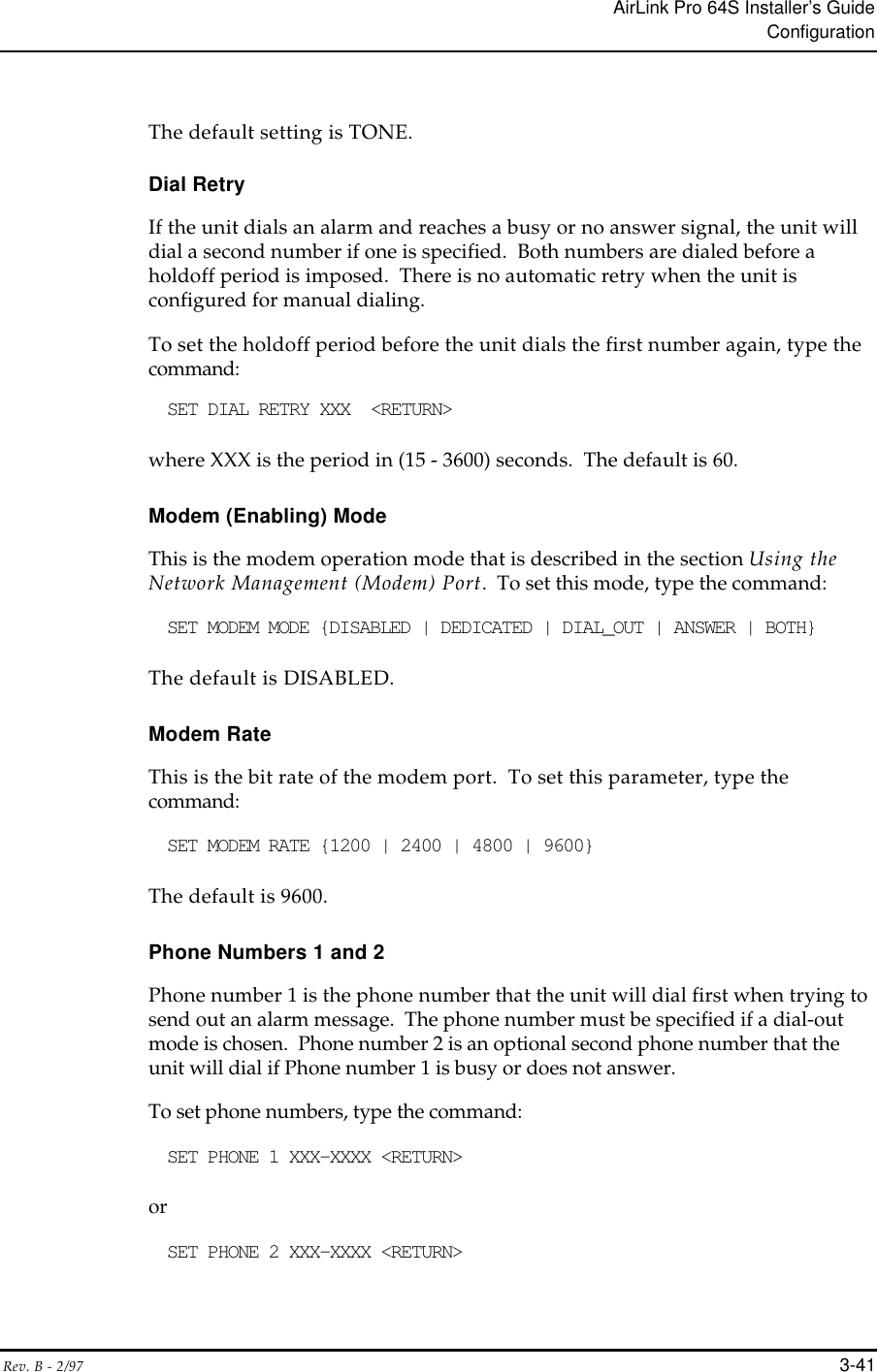
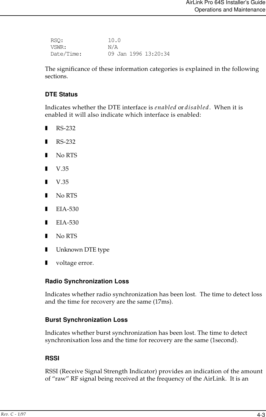
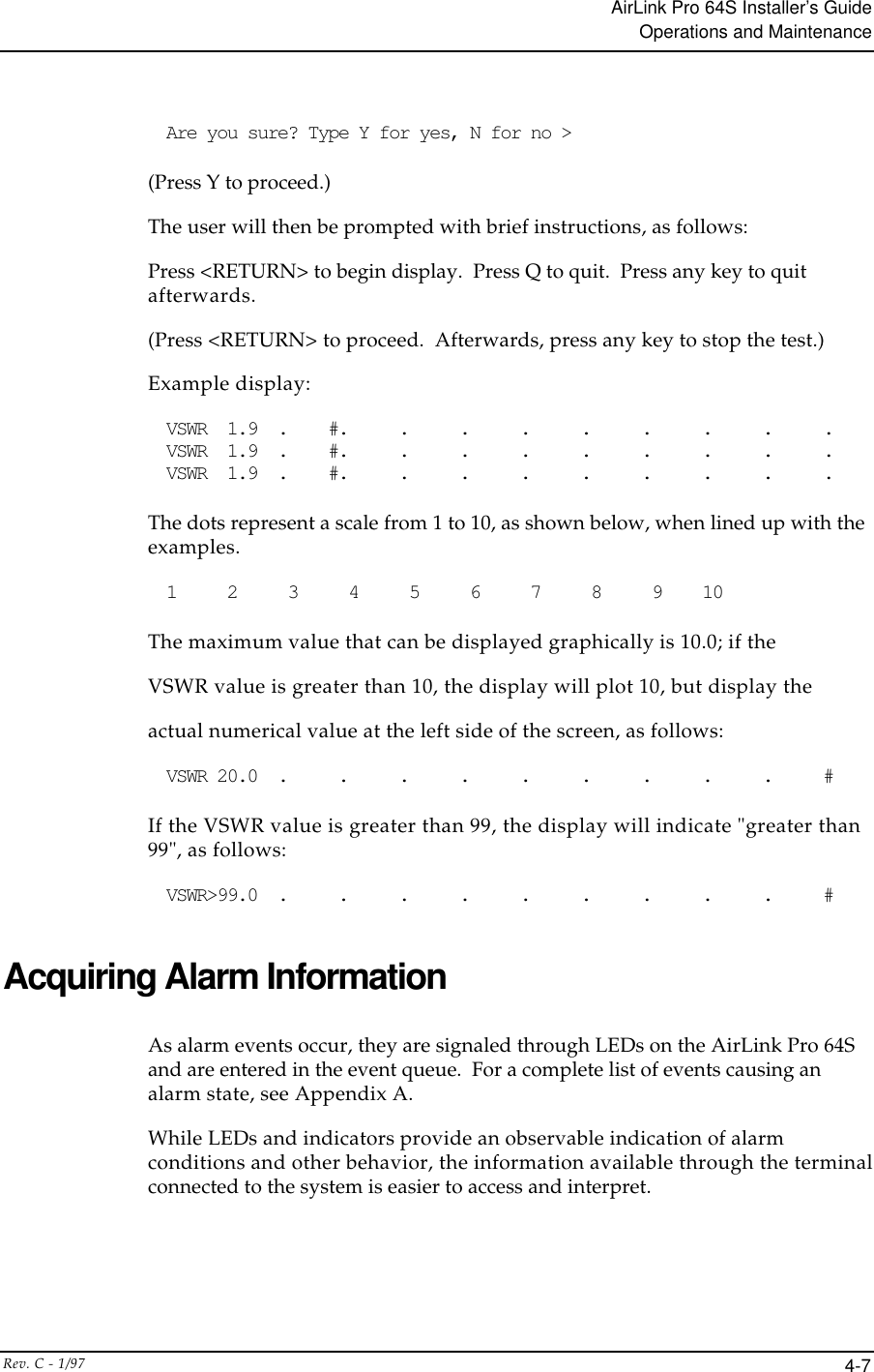
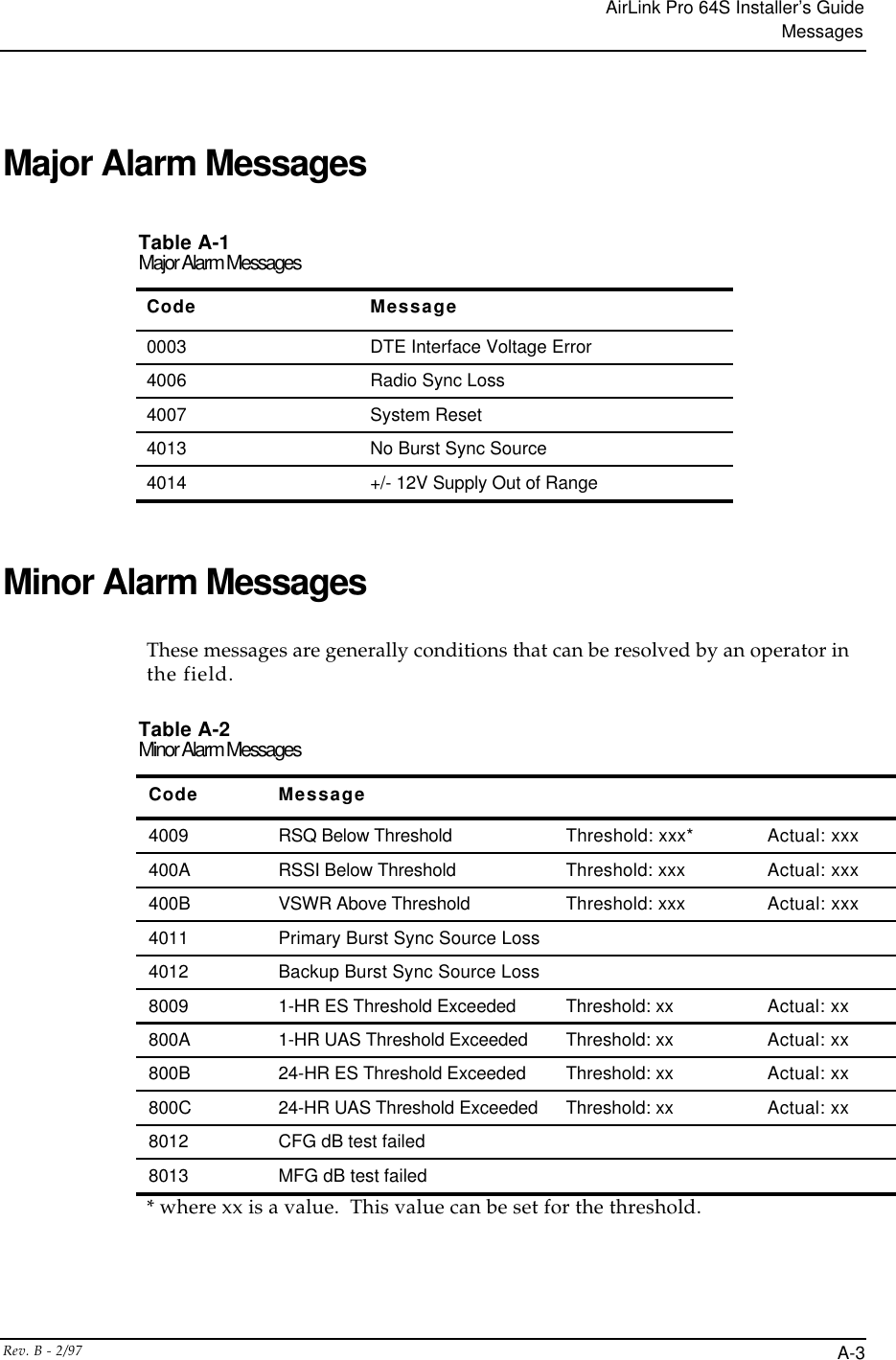
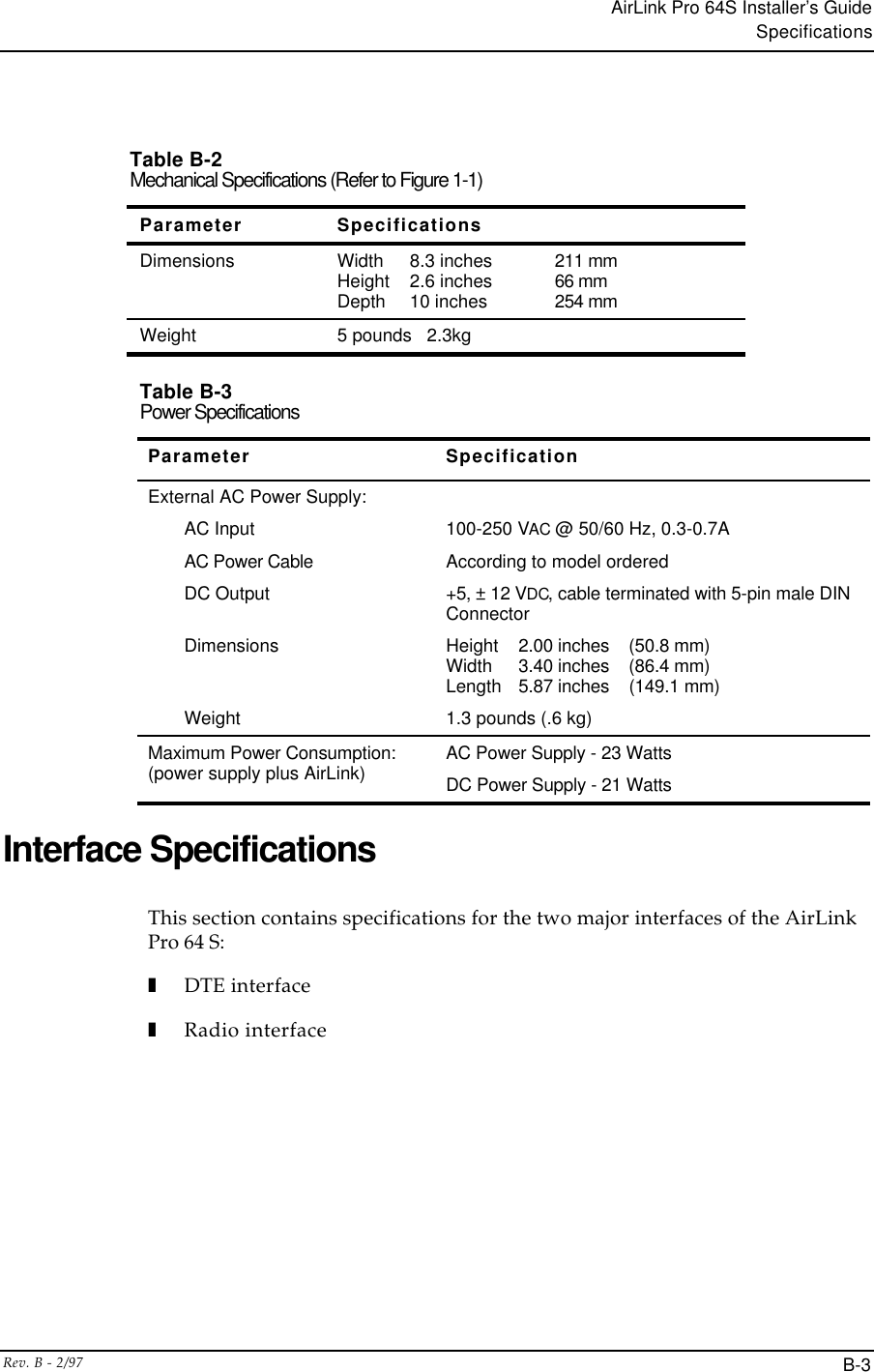
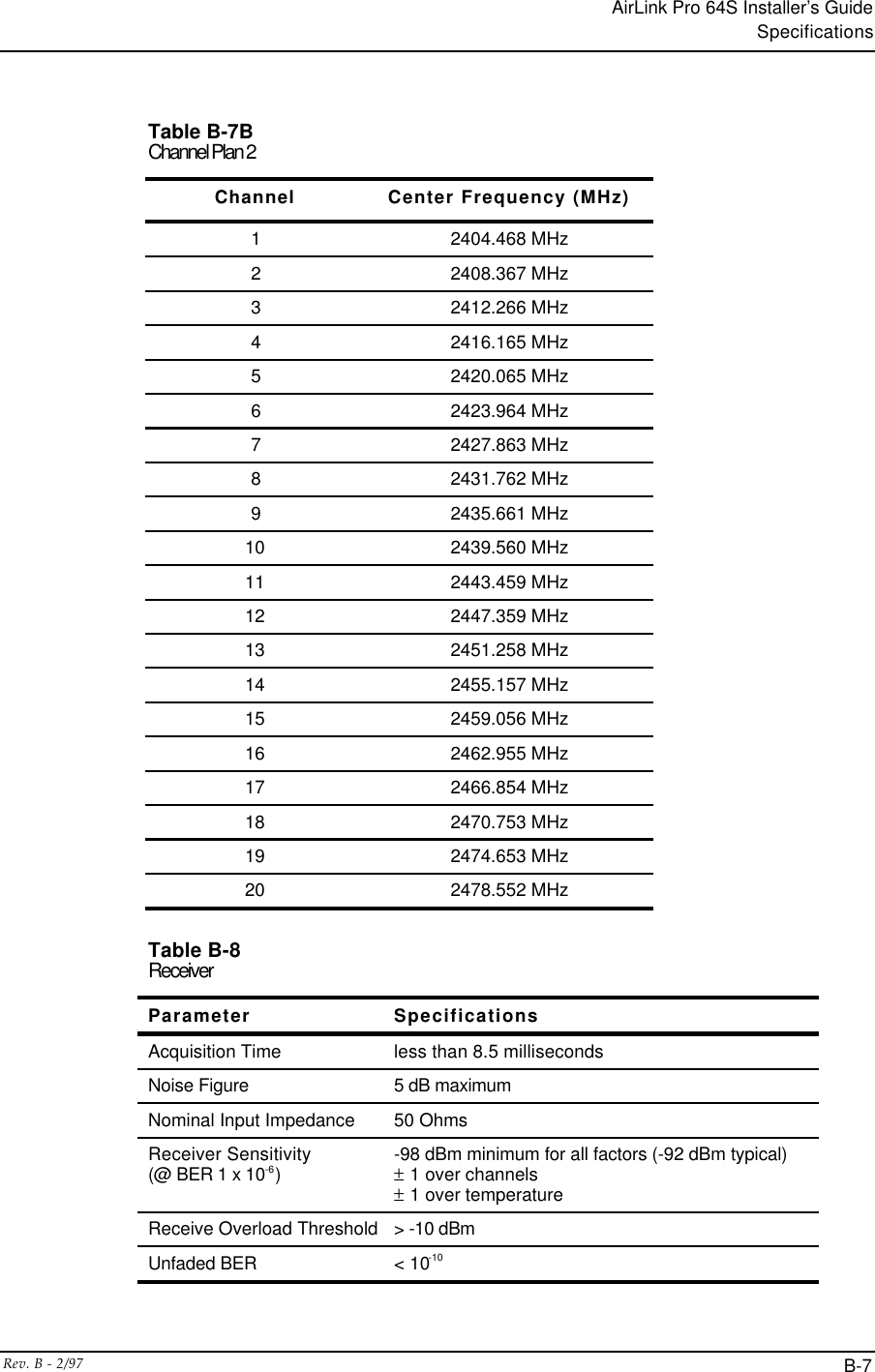
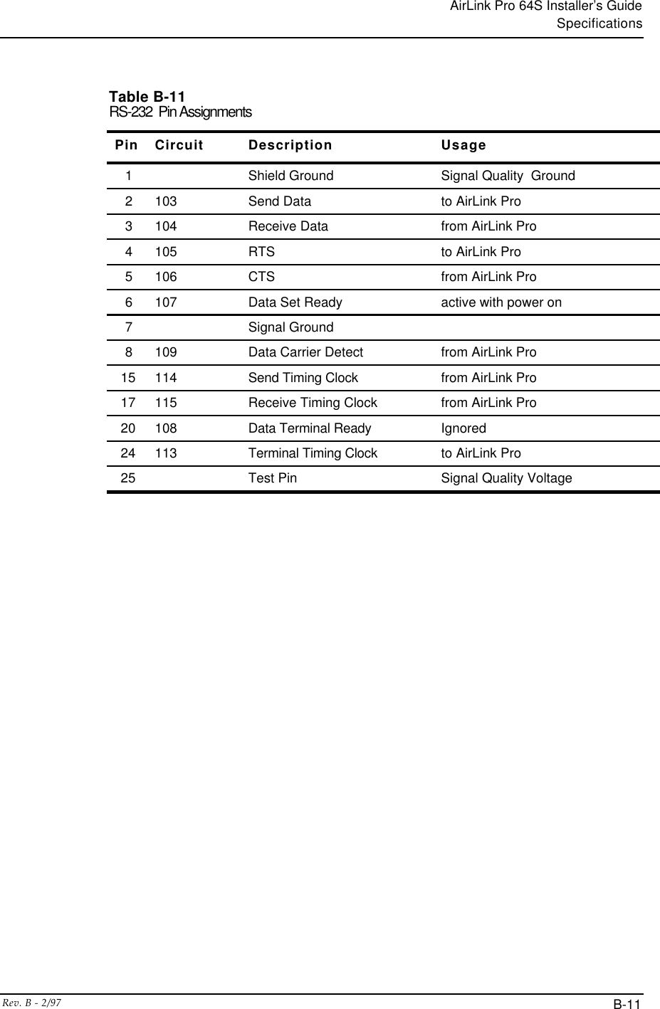
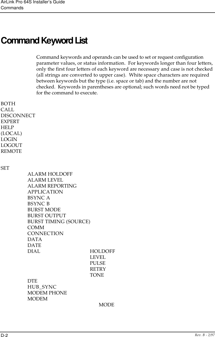
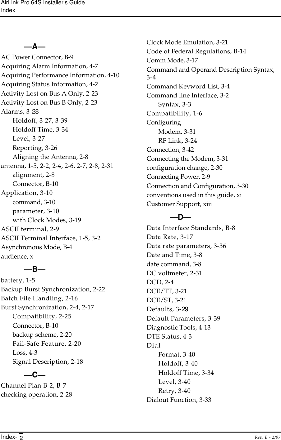
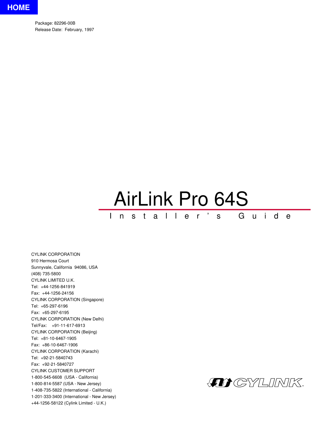
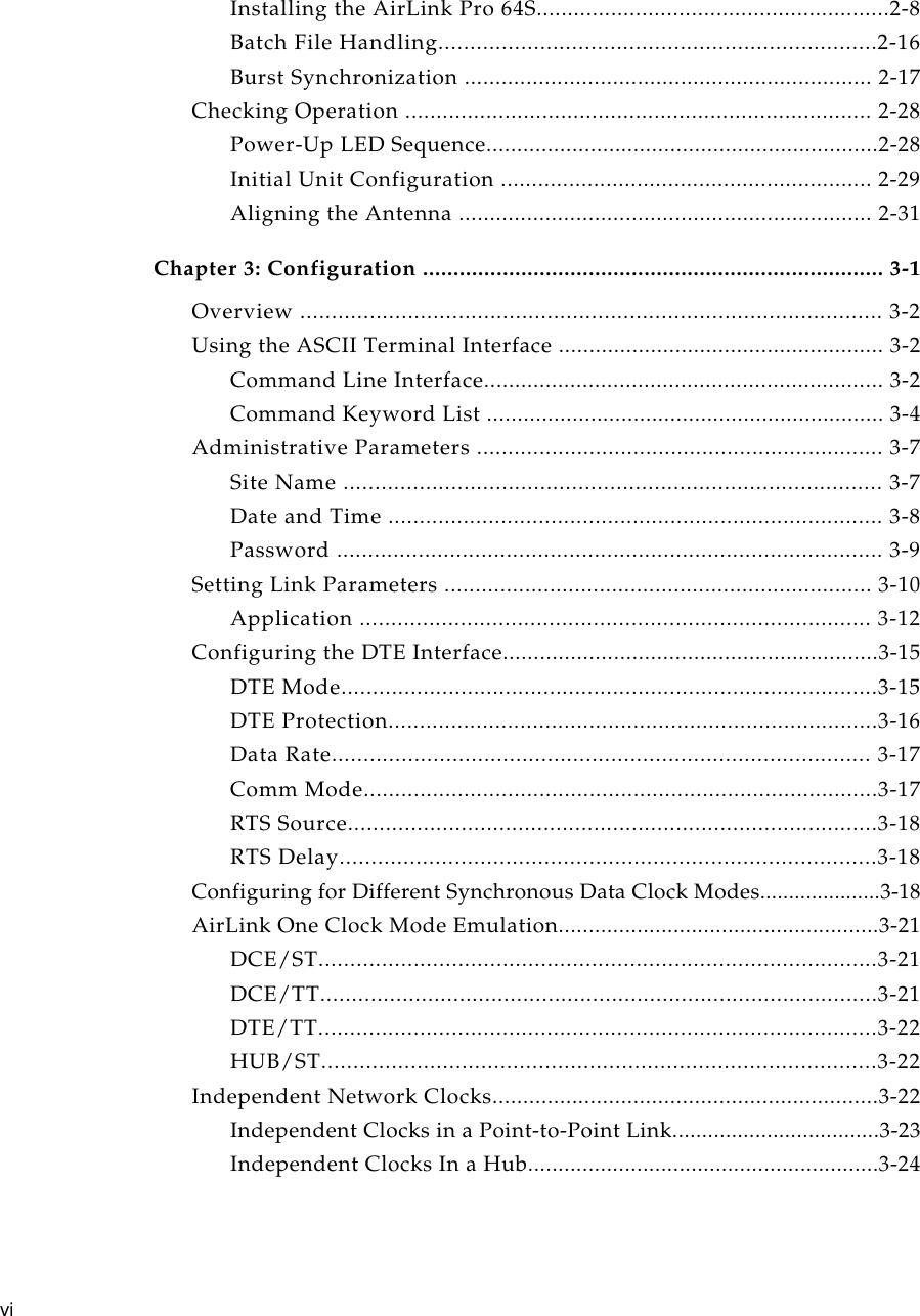
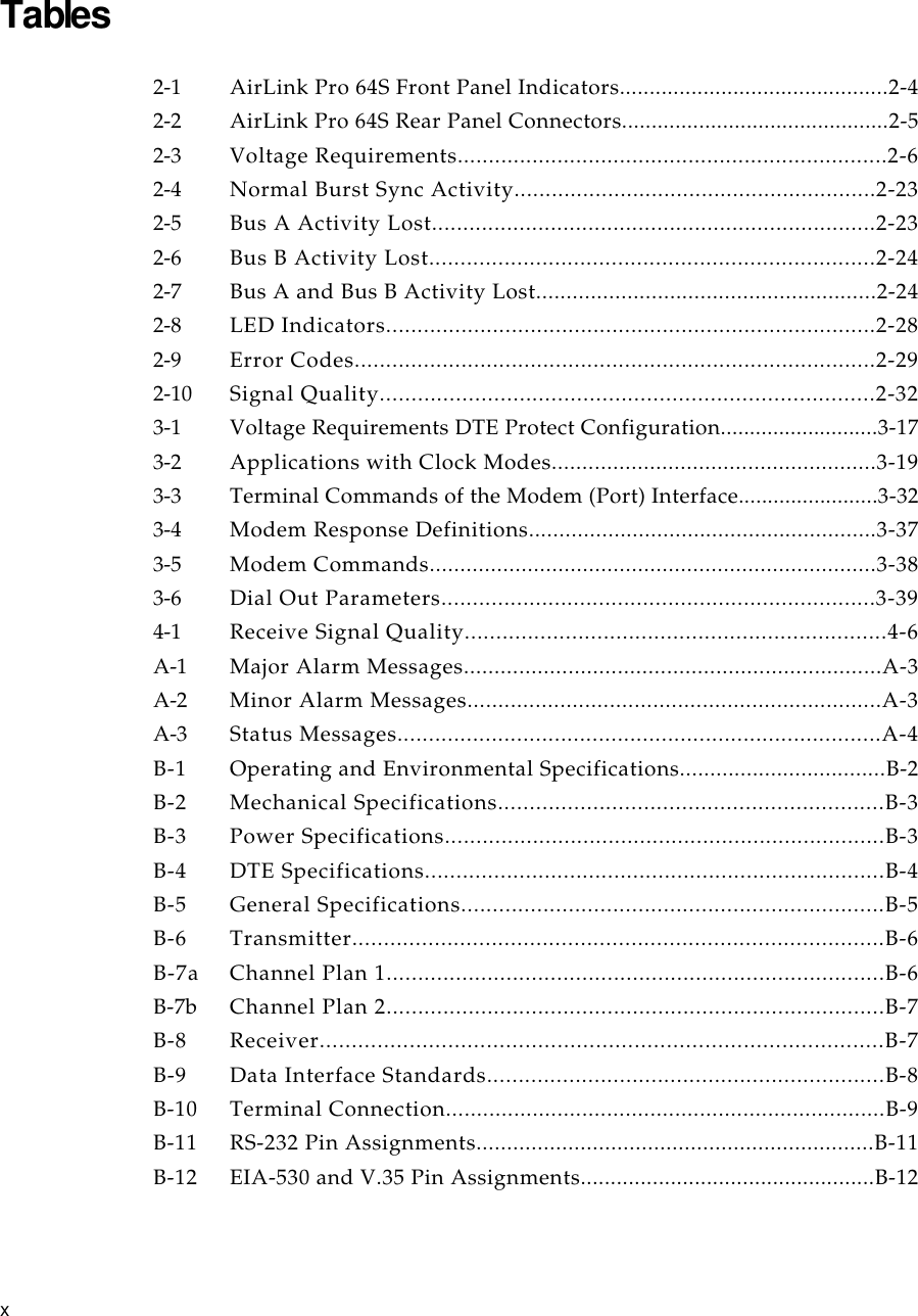
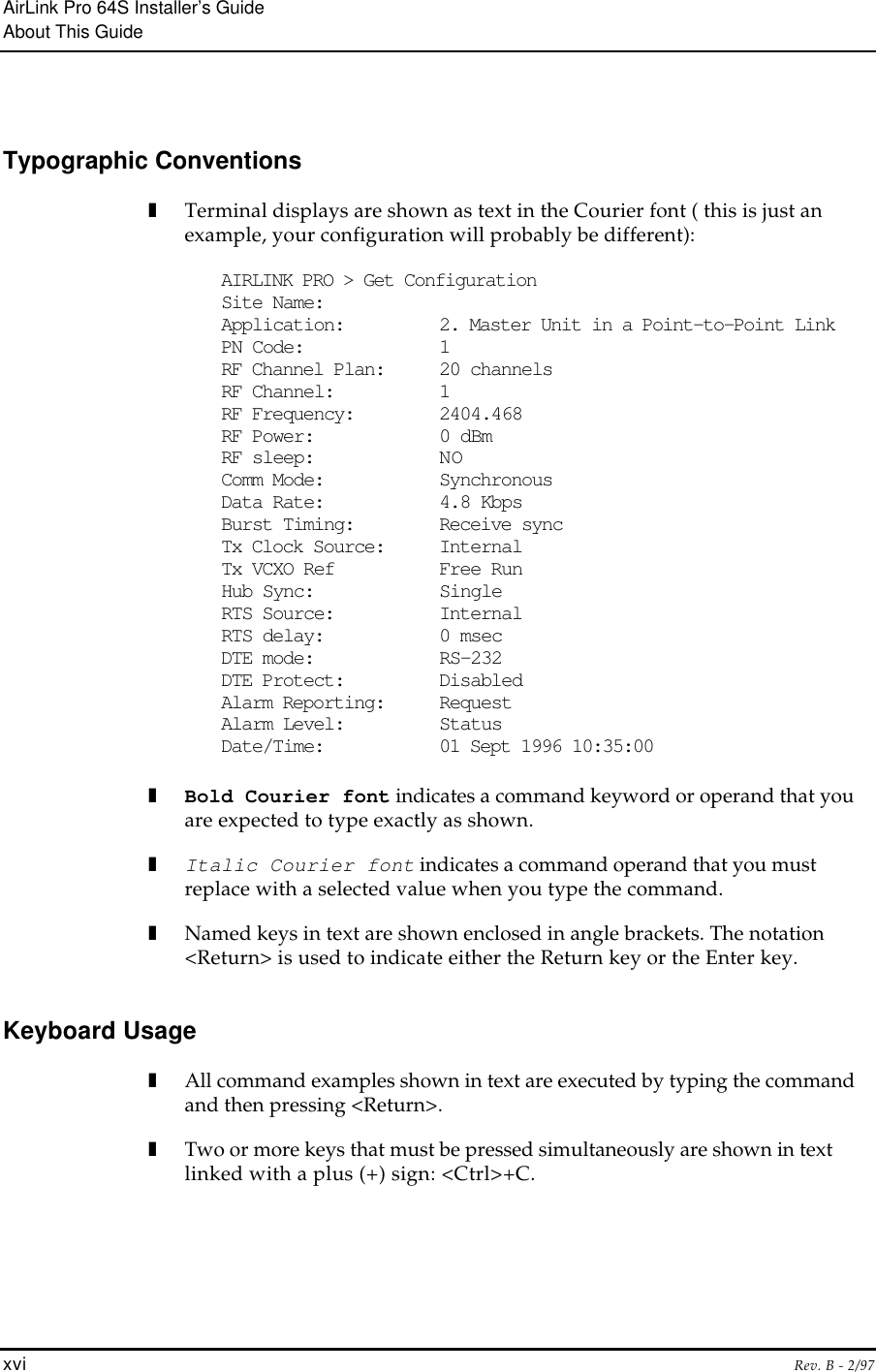
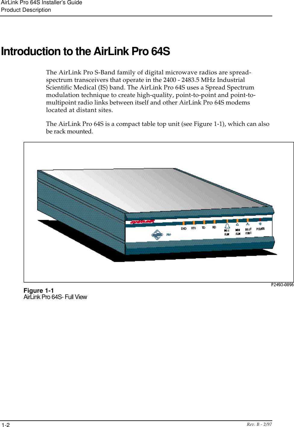
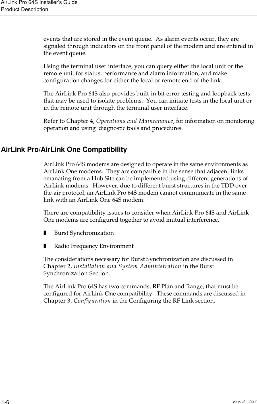
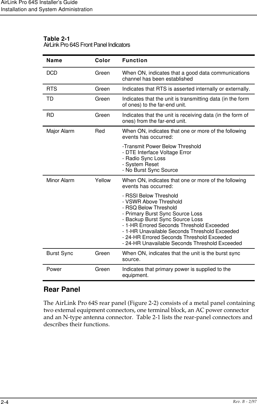
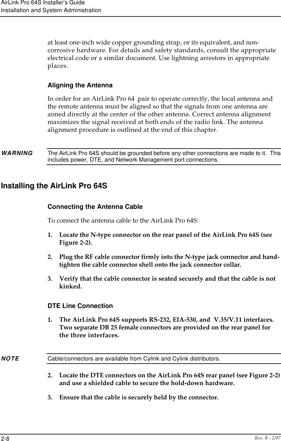
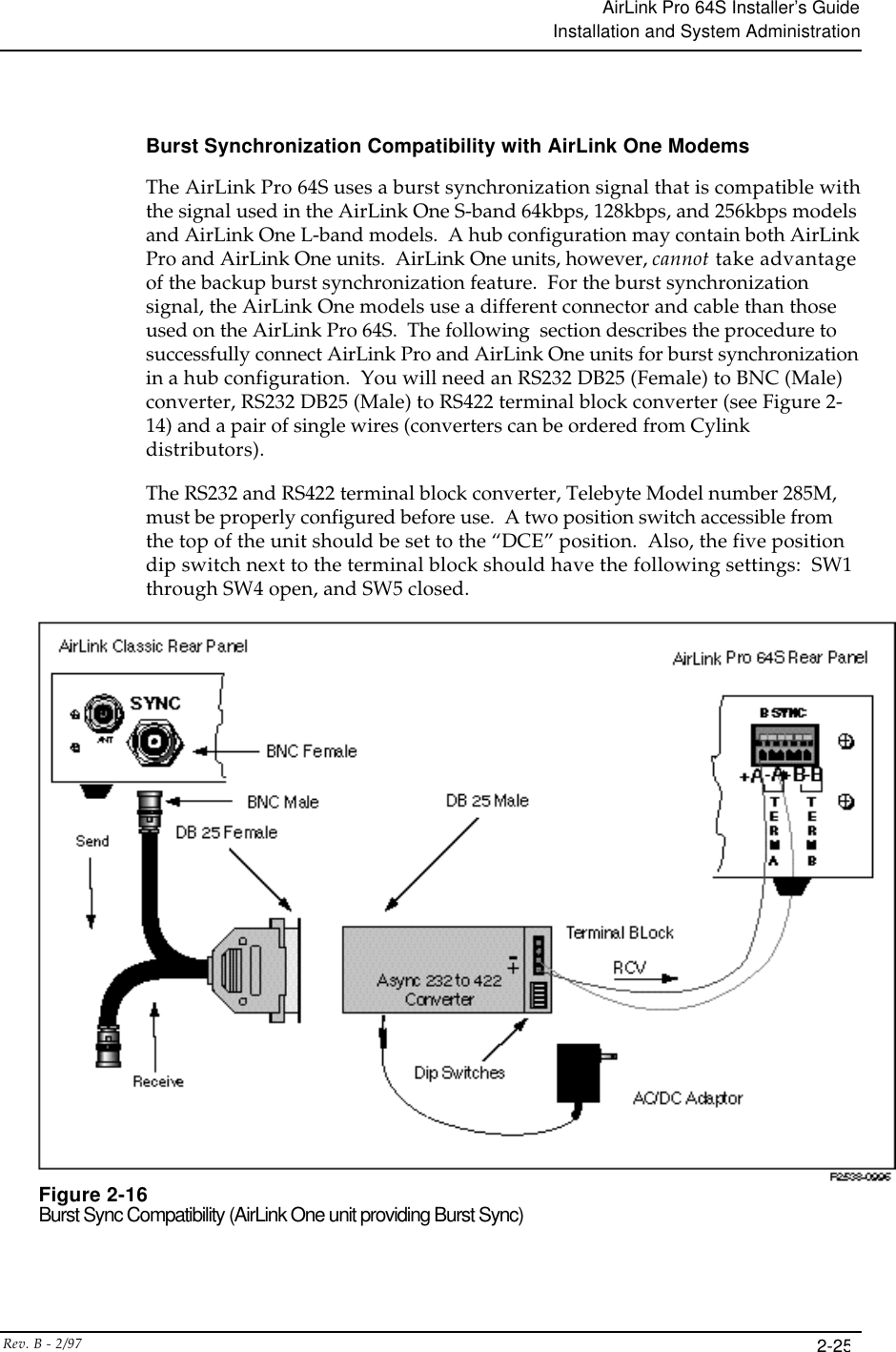
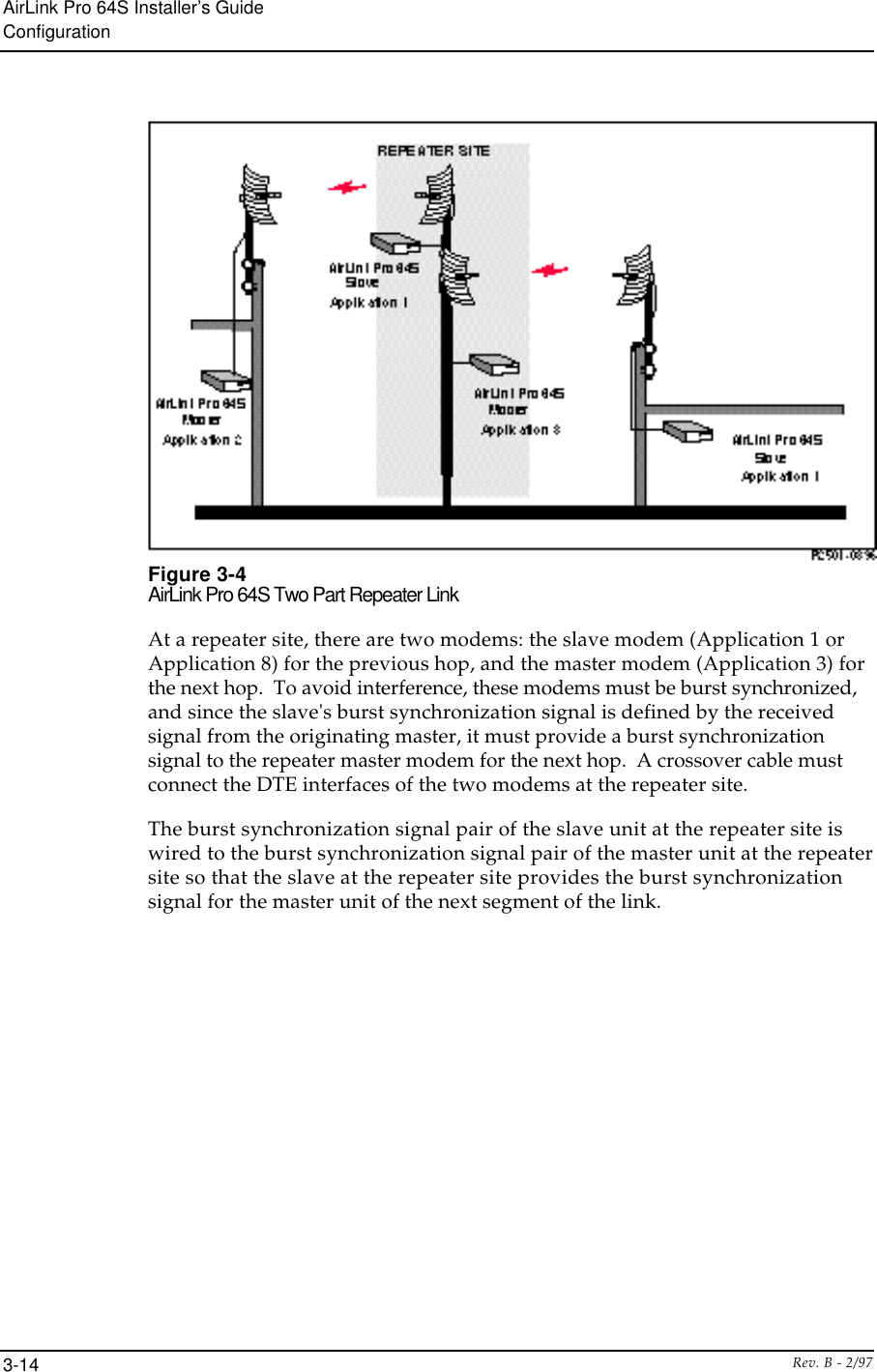
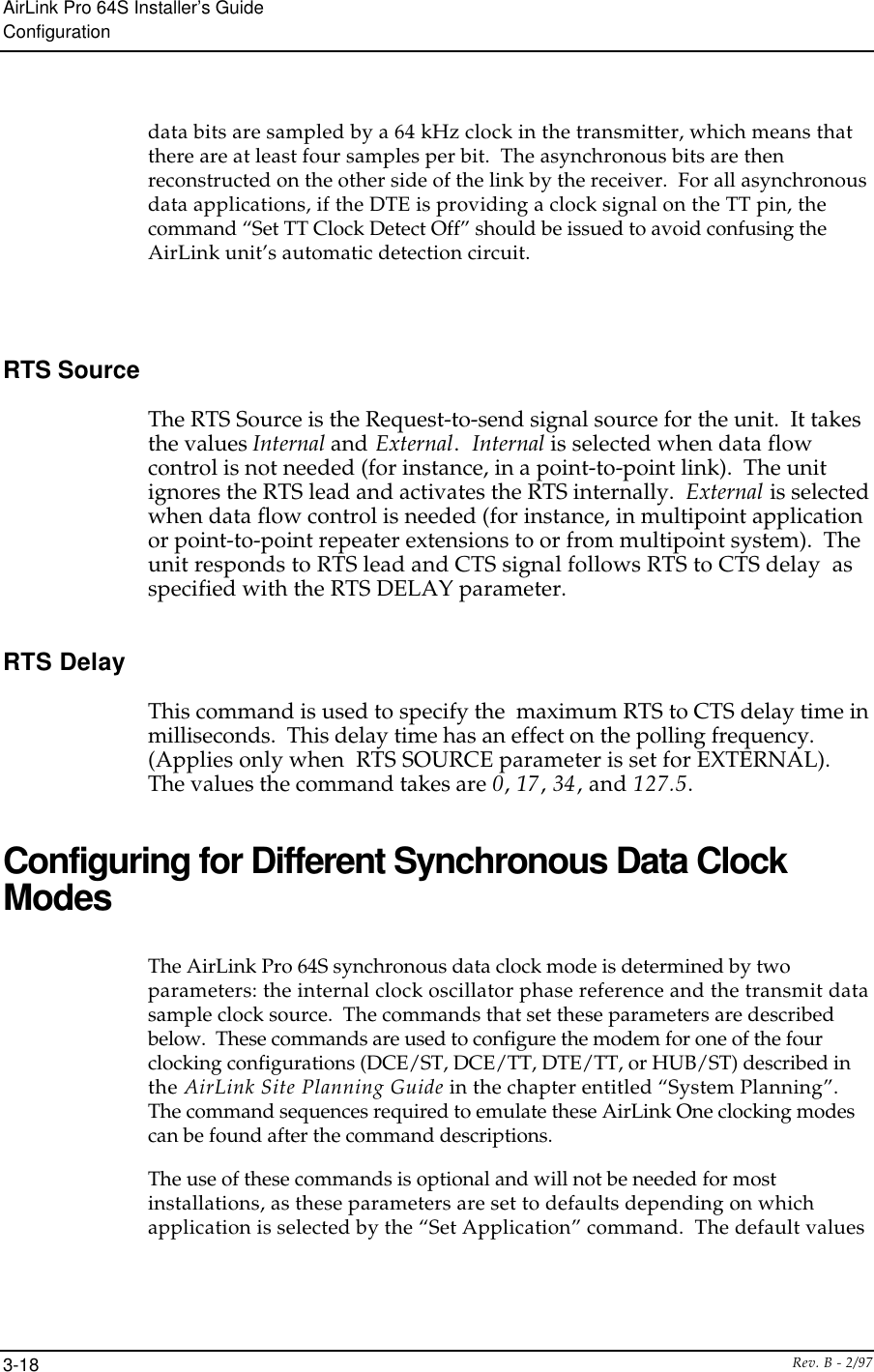
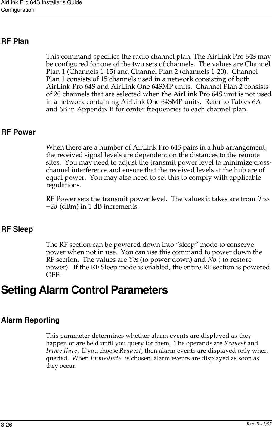
![AirLink Pro 64S Installer’s GuideConfigurationRev. B - 2/973-12Figure 3-2Point-to-Multipoint ApplicationHub Application (Applications 4, 5, and 6)A hub application is used when two or more full-duplex links emanate from asingle centralized location. In a hub configuration, two or more units are co-located at the hub site. One of the units is the synchronizing unit, theReference Master (Application 4), which generates the burst timing referencefor the other units. This burst synchronization minimizes near-end inter-channel interference among the units and all the units transmit and receive atthe same time. Should the Reference Master unit fail, a second unit, Back upmaster at a Hub (Application 5), is designated to provide the burstsynchronization signal to the rest of the units at the Hub. All other units areconfigured as Subordinate Master units (Application 6) [ See the section “BurstSynchronization” in Chapter 2].](https://usermanual.wiki/Wave-Wireless/AIRLINKPRO/User-Guide-29583-Page-68.png)
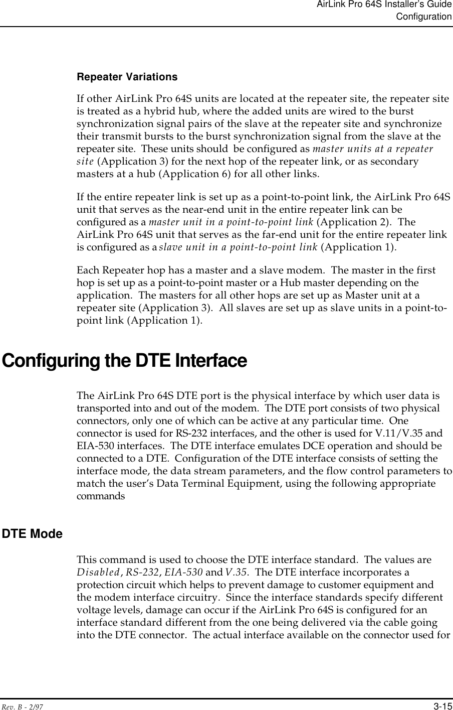
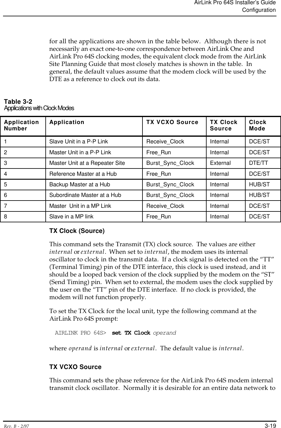
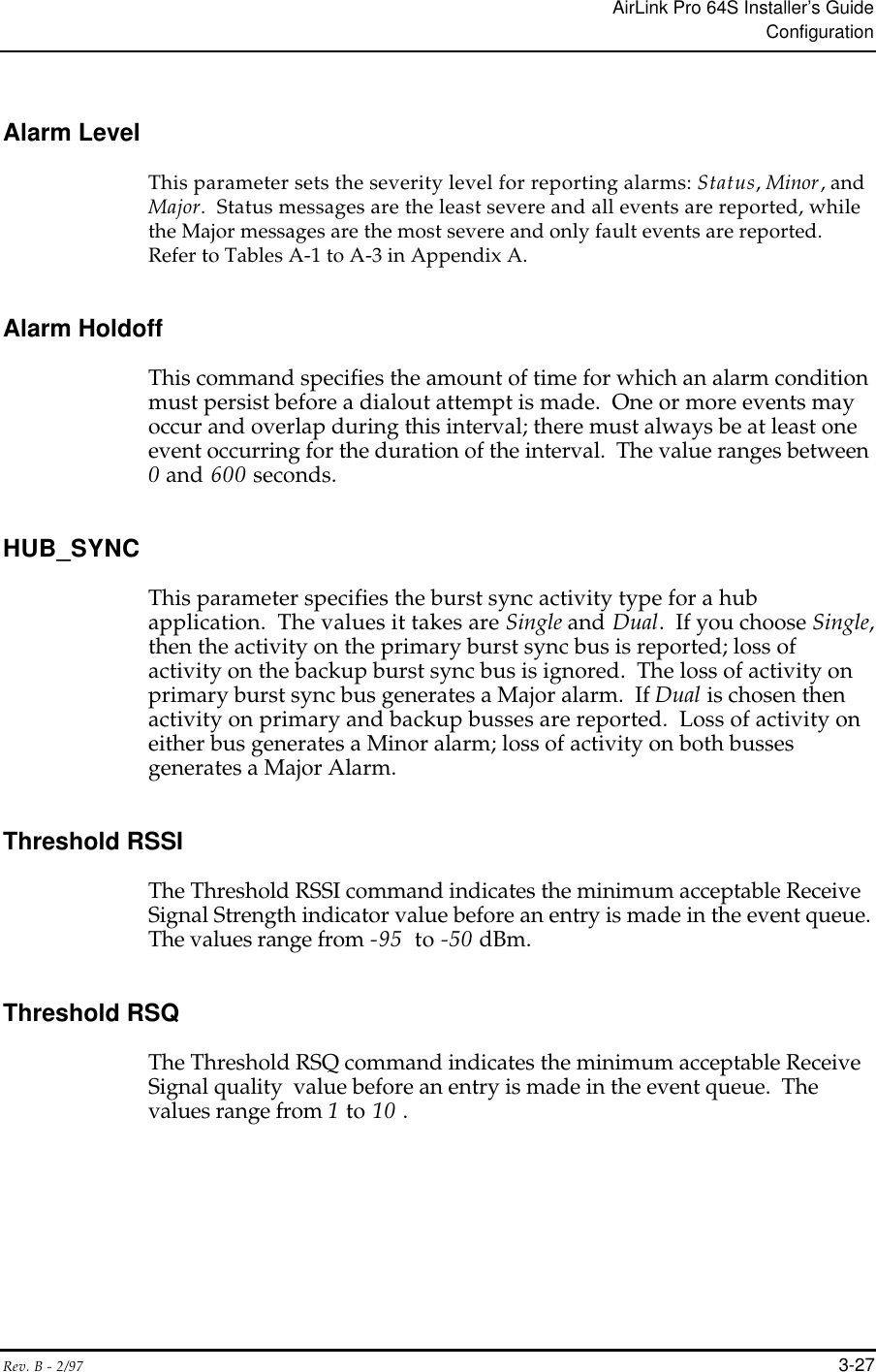


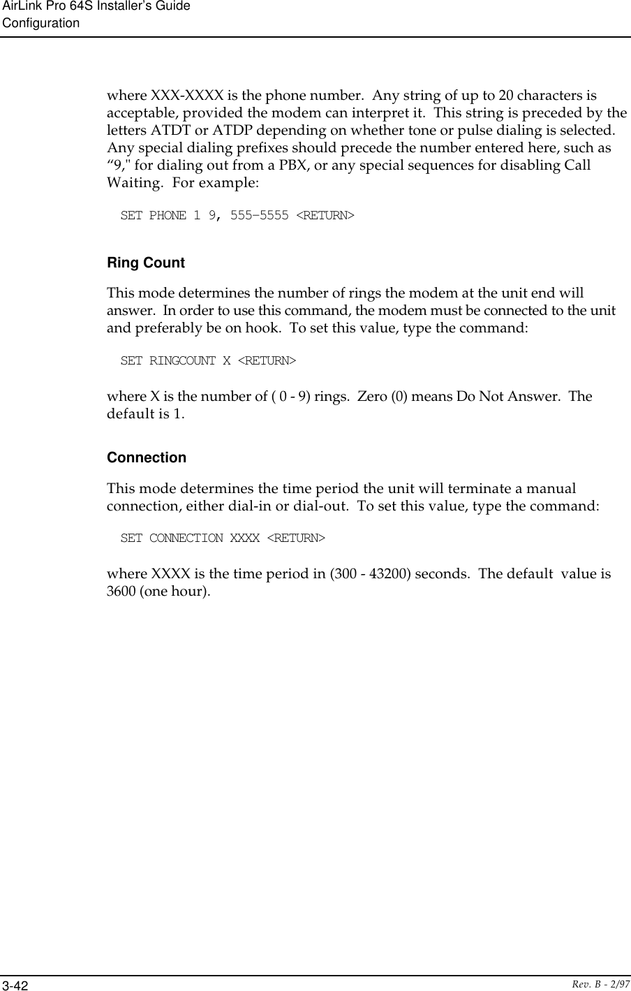
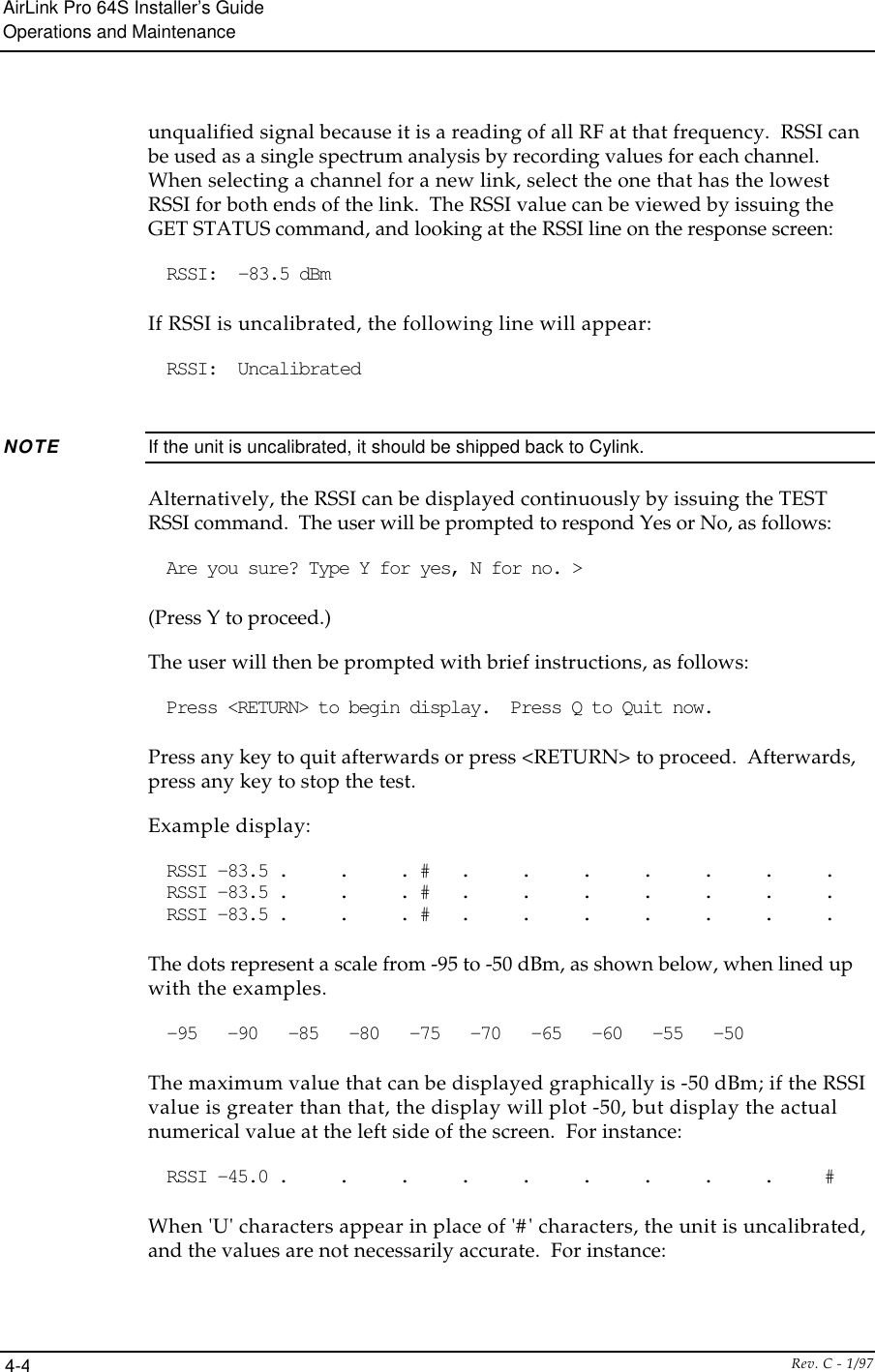
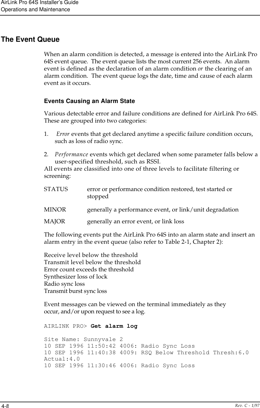
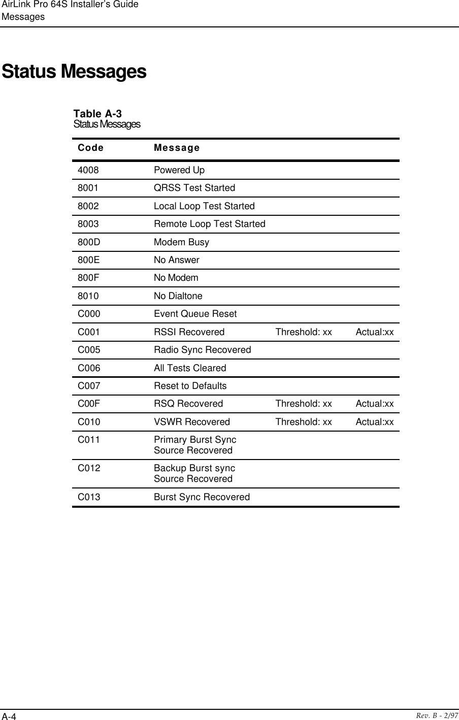
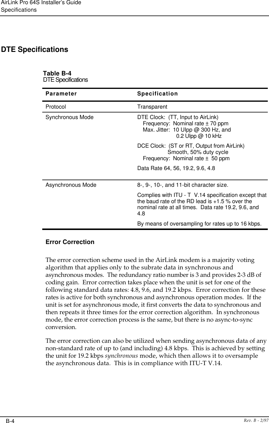
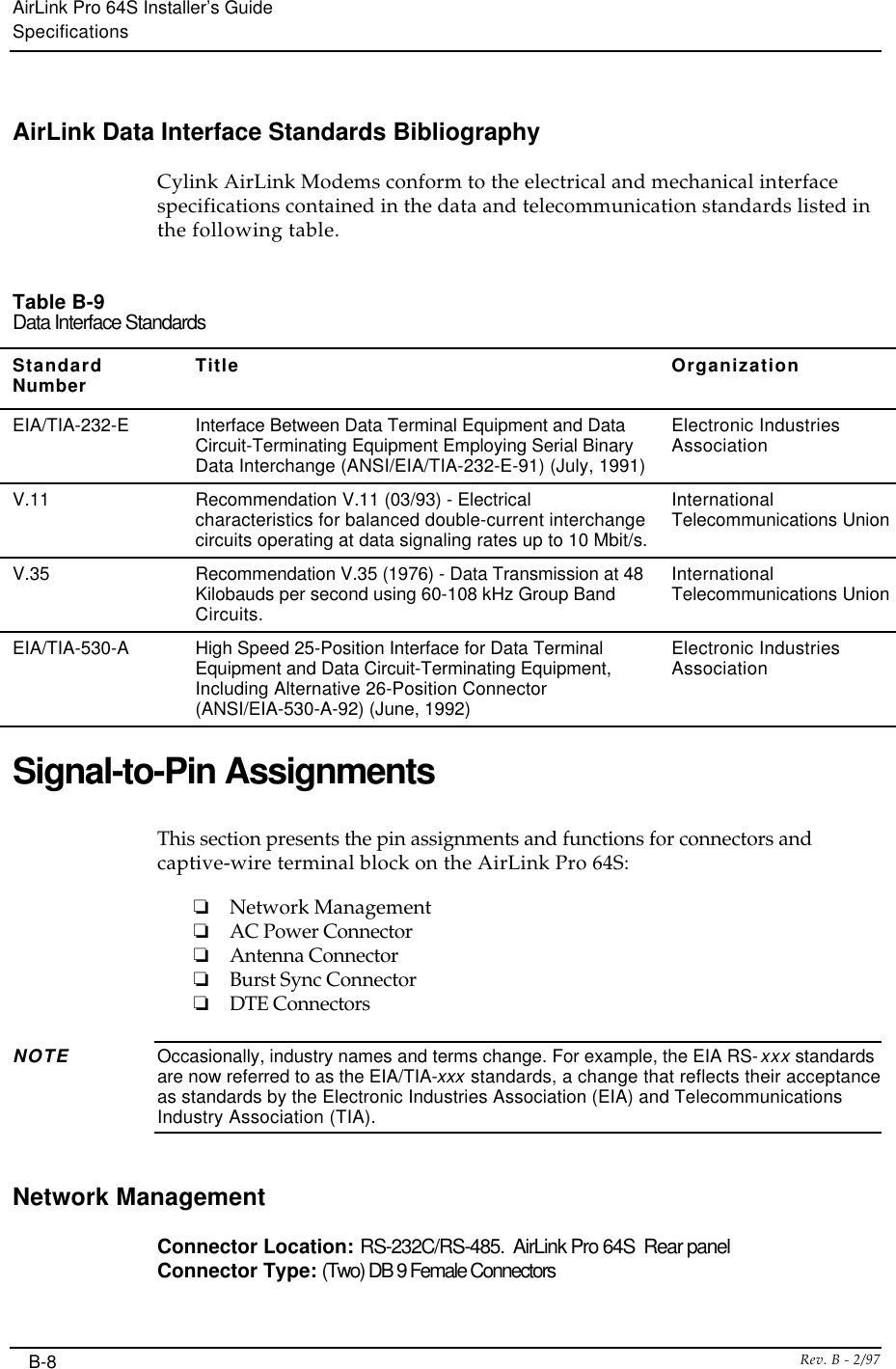
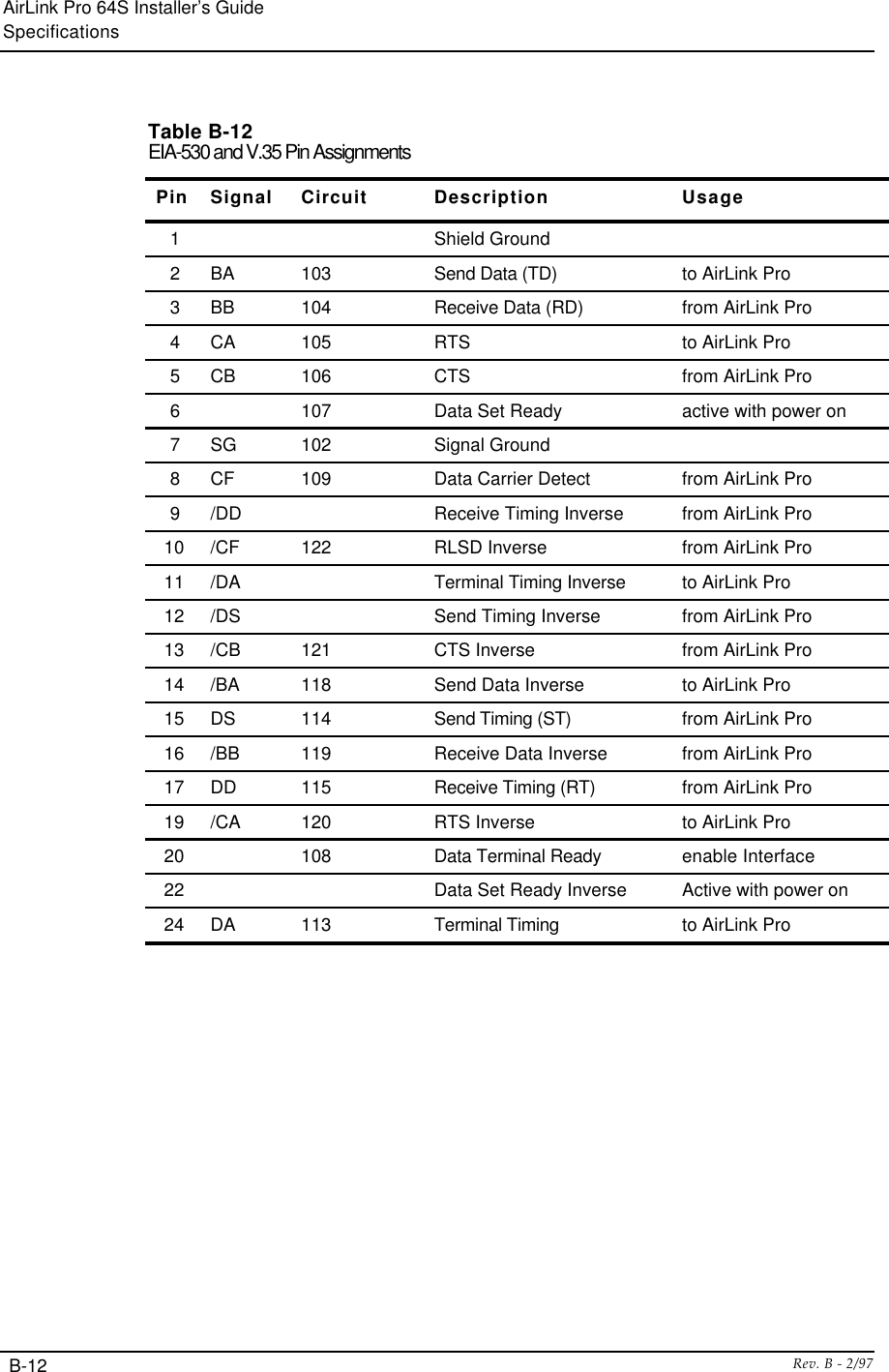
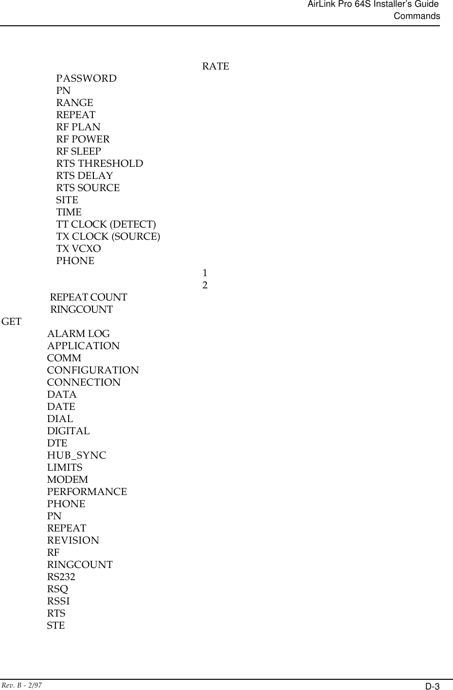
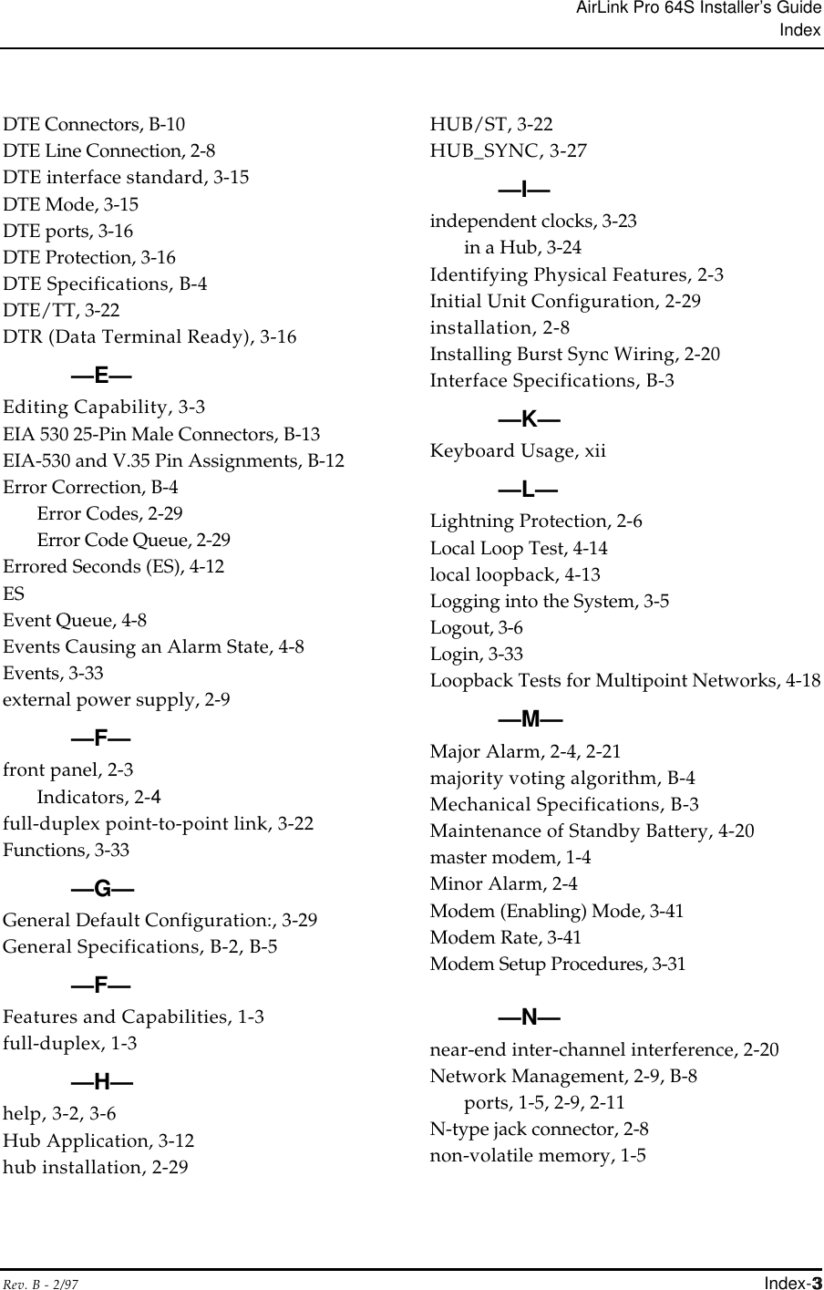
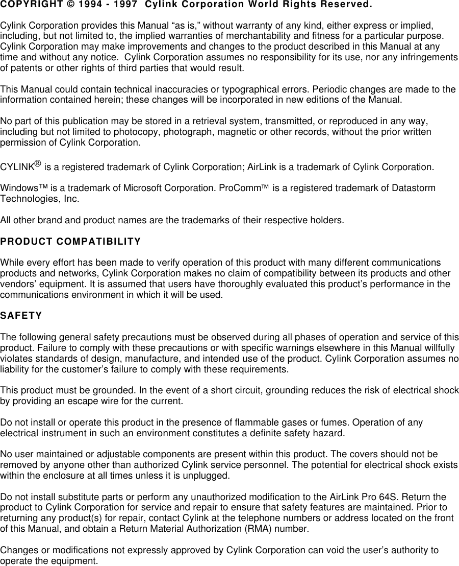
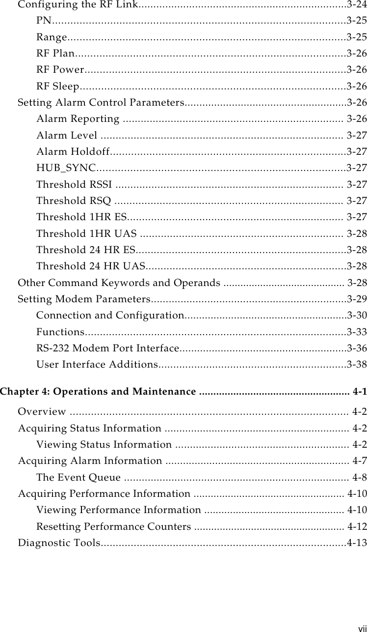
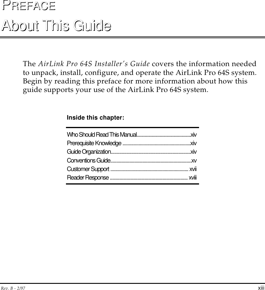
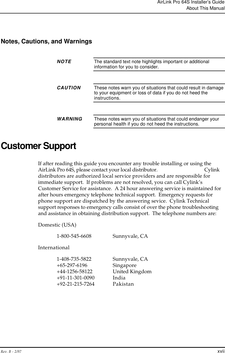
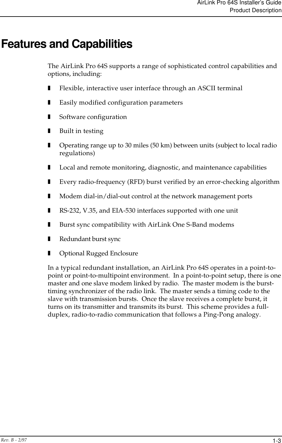
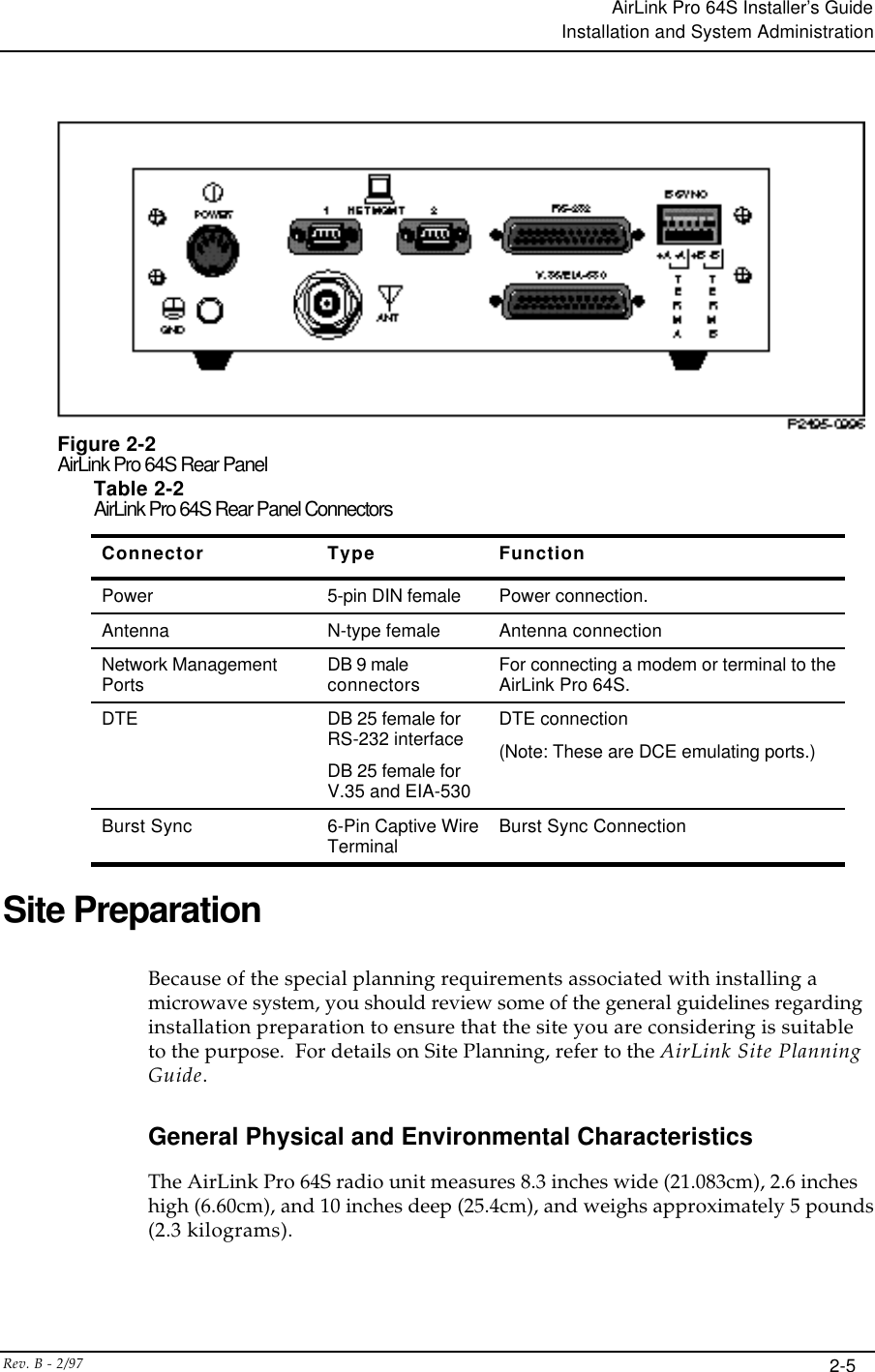
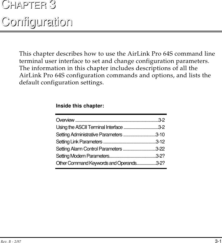
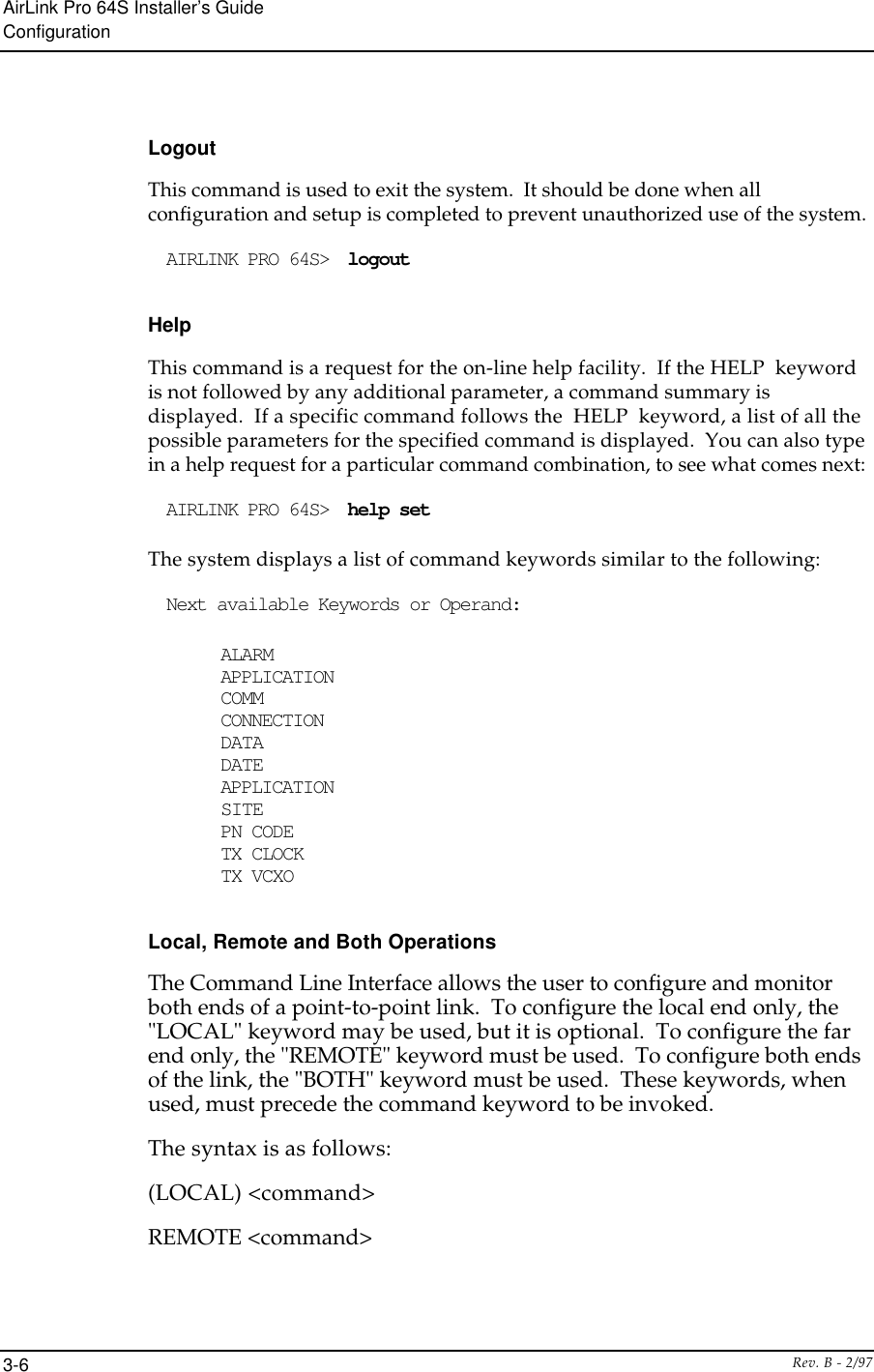
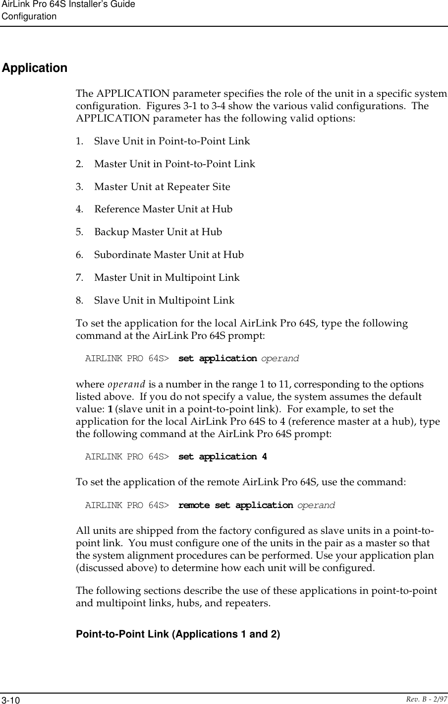
![AirLink Pro 64S Installer’s GuideConfigurationRev. B - 2/973-38OK Successful execution of non-dial commandCONNECT [XXXX] carrier detected; XXXX = numeric bit rateRING Ringing detectedNO CARRIER No connection established, or connection lostERROR Error in command lineNO DIALTONE No dial tone presentBUSY Busy signalNO ANSWER 5 seconds of silence not detected if '@' dial modifier was used.User Interface AdditionsTable 3-5Modem CommandsParameter SpecificationSET ALARM HOLDOFF 0-600 (seconds)SET CONNECTION 0 - 43200 (seconds; 0 means no time-out)SET DIAL {TONE | PULSE}SET DIAL HOLDOFF 3-5000 (minutes, repeat dial holdoff)SET DIAL LEVEL MAJOR | MINOR | STATUSSET DIAL RETRY 15-3600 (seconds)SET MODEM MODE {DISABLED | DEDICATED DIAL_OUT | ANSWER | BOTH}SET MODEM RATE {1200 | 2400 | 4800 | 9600}SET PHONE 1 (XXX) XXX-XXXXSET PHONE 2 (XXX) XXX-XXXXSET REPEAT COUNT 0-99SET RINGCOUNT 0-9The GET MODEM configuration command retrieves all of the Modem Commandparameters. This command produces a screen displaying all of the settings, thedial-out status, and the date and time. In addition, all the SET and GETcommands are available via the REMOTE prefix.The following commands are also supported:CALL 1 manual connectCALL 2 manual connect](https://usermanual.wiki/Wave-Wireless/AIRLINKPRO/User-Guide-29583-Page-94.png)