Wave Wireless SL9202 Wireless LAN User Manual allPH900manual
Wave Wireless Corporation Wireless LAN allPH900manual
UserManual.wiki
>
Wave Wireless
>
SL9202 User Manual
users manual
Navigation menu
Upload a User Manual
Namespaces
Wiki Guide
HTML
PDF
Info
Views
User Manual
Discussion / Help
Navigation

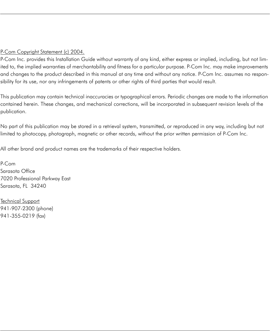
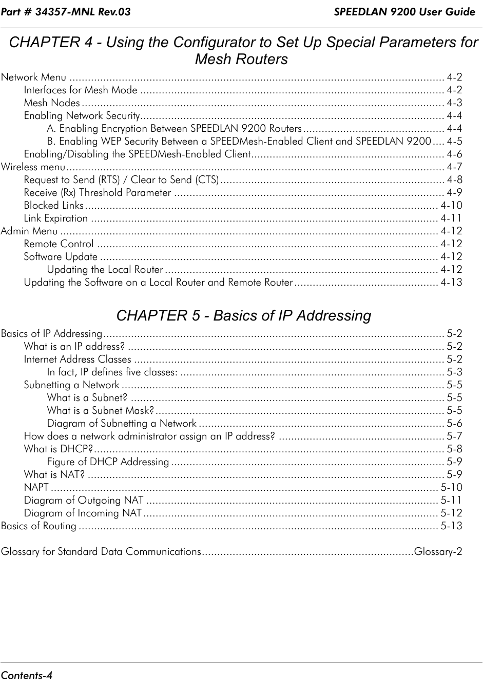


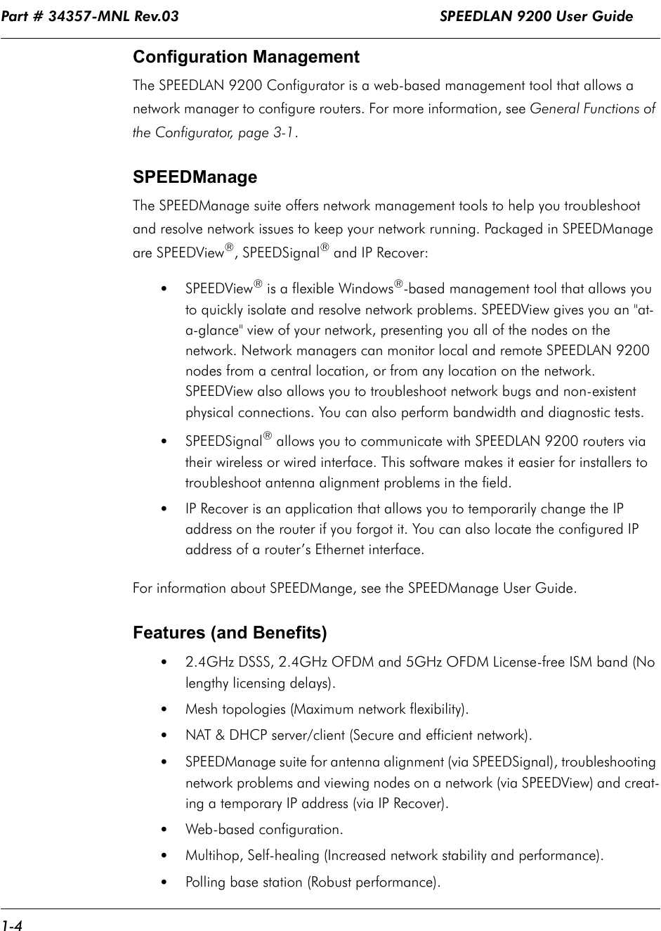
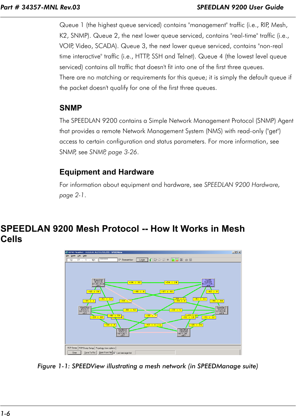
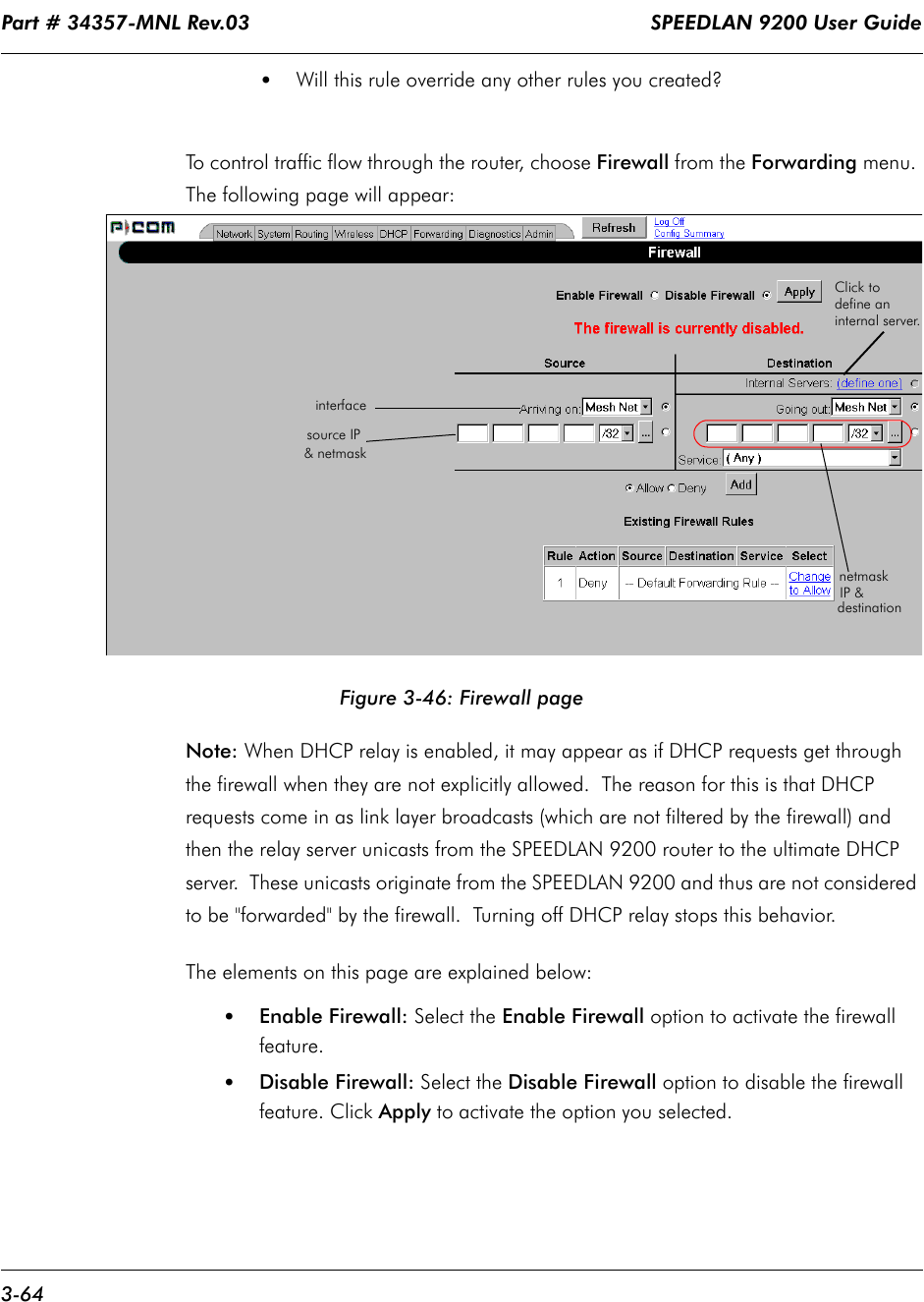
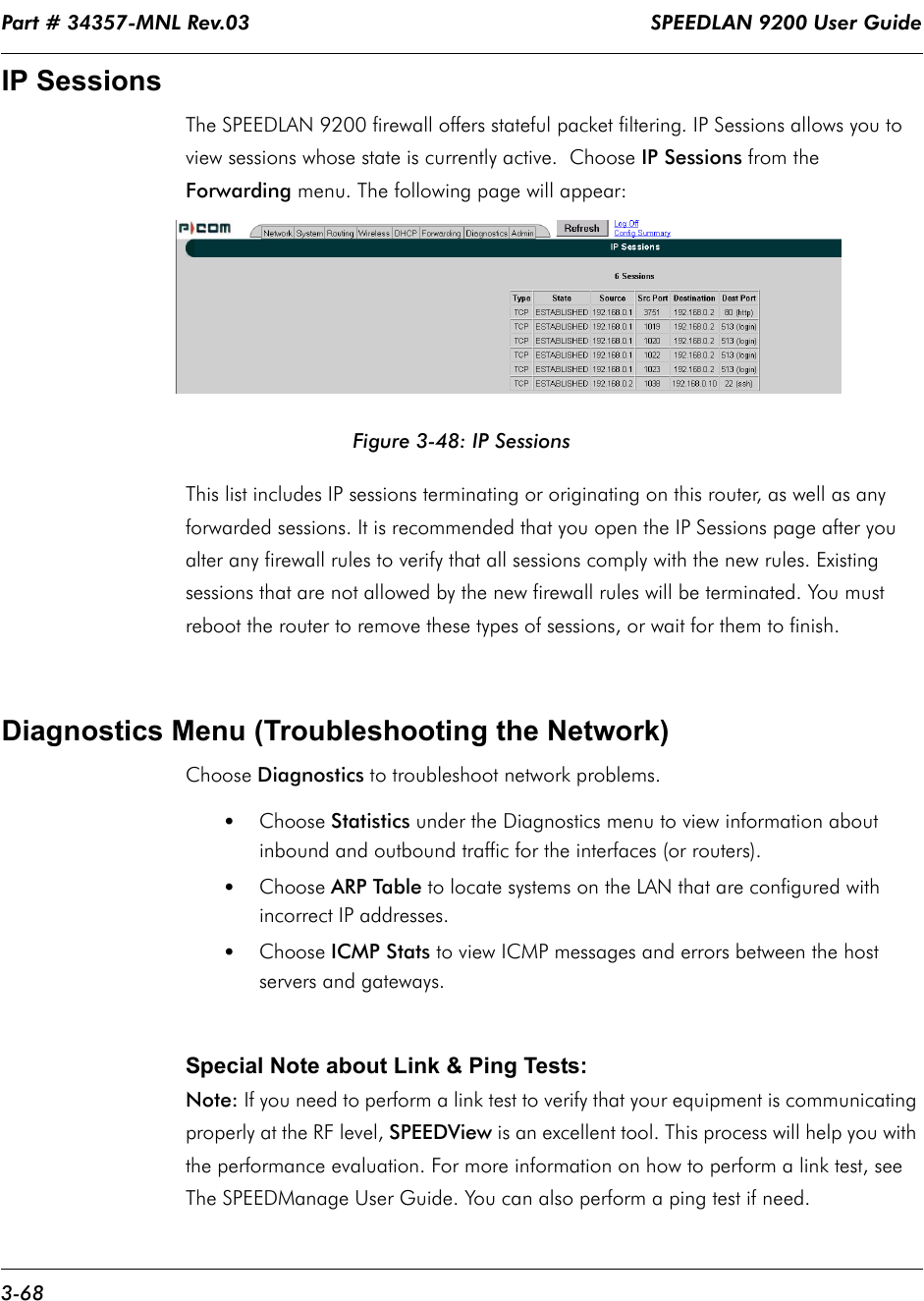
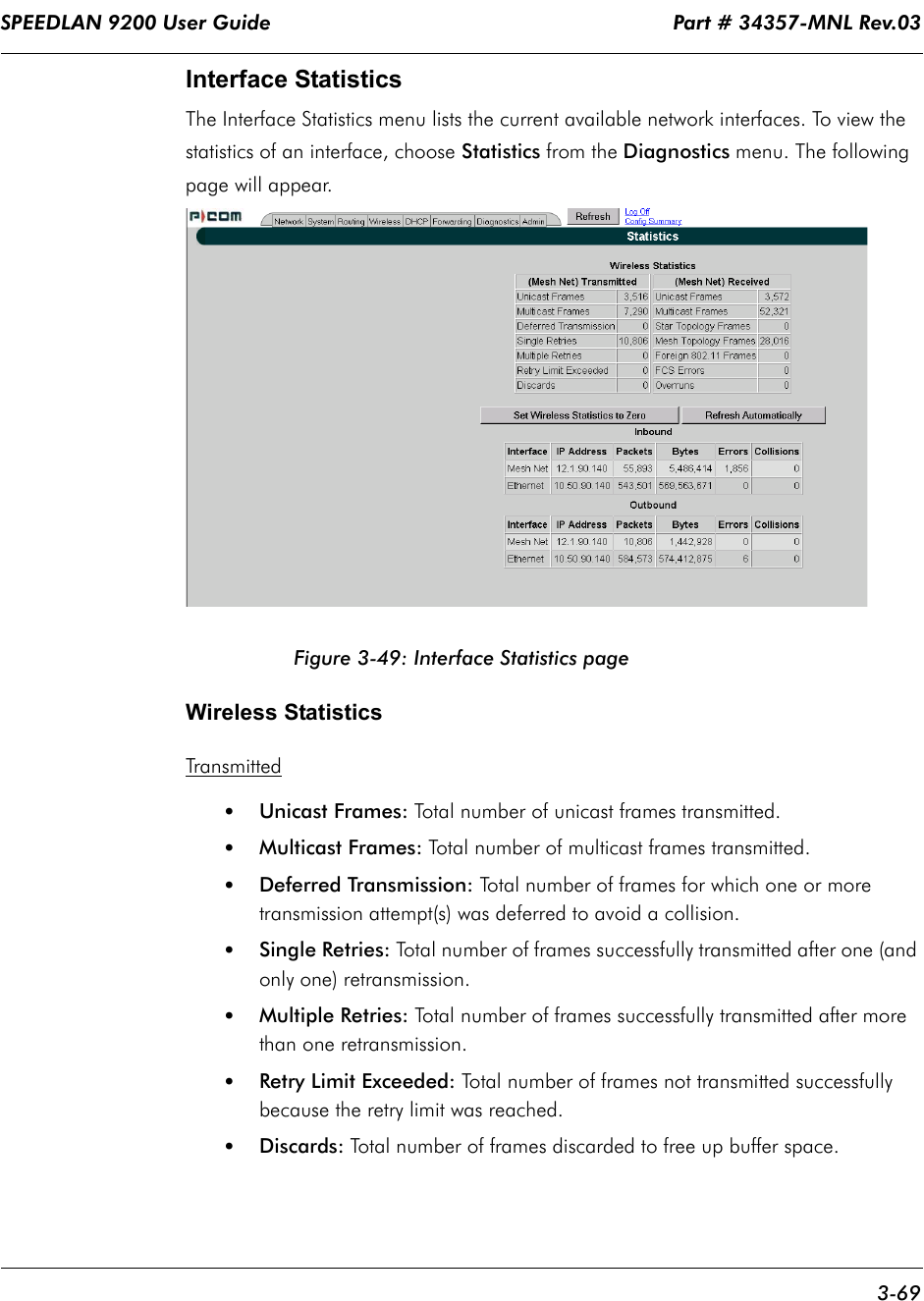
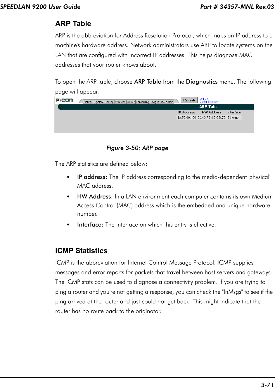
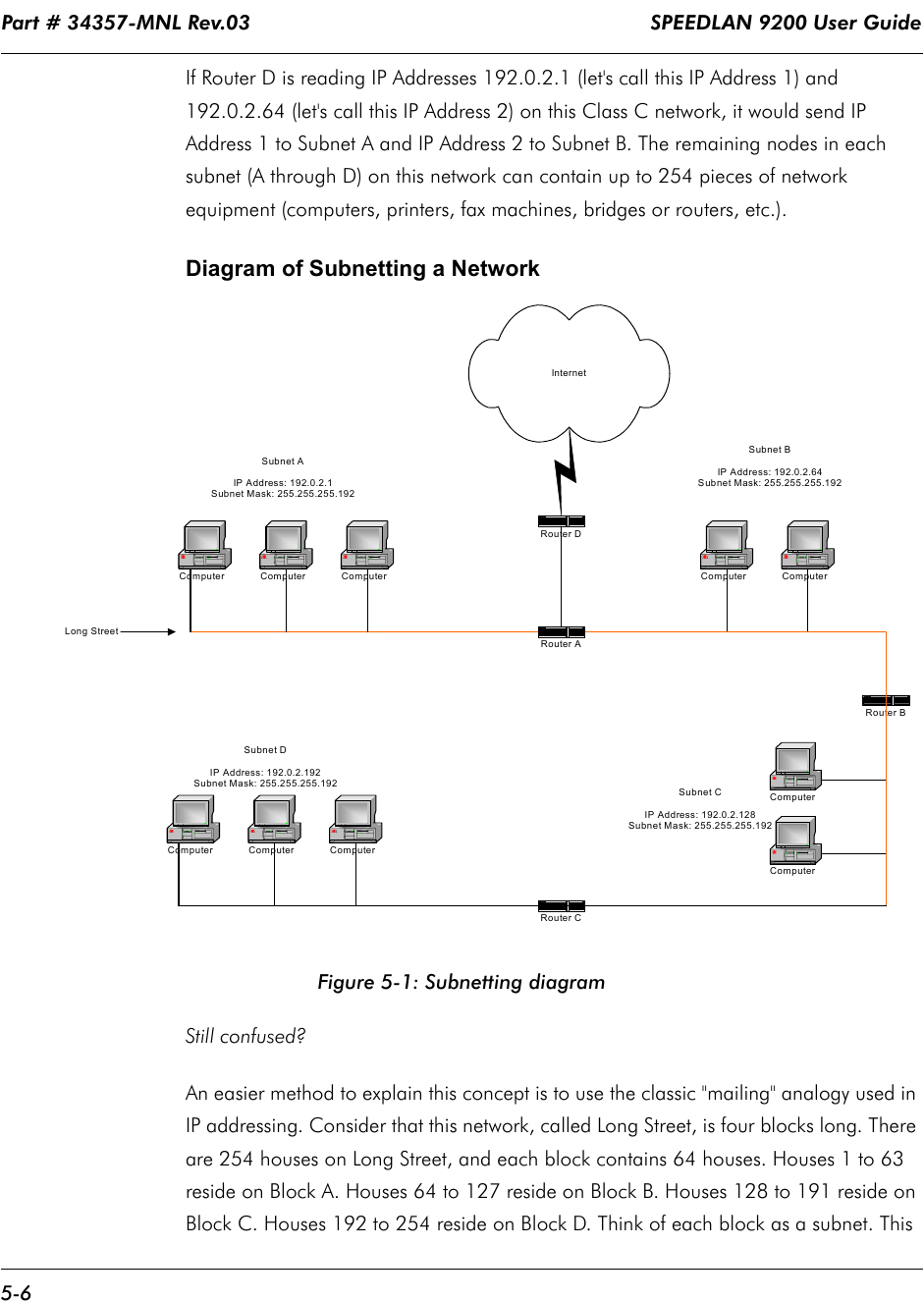
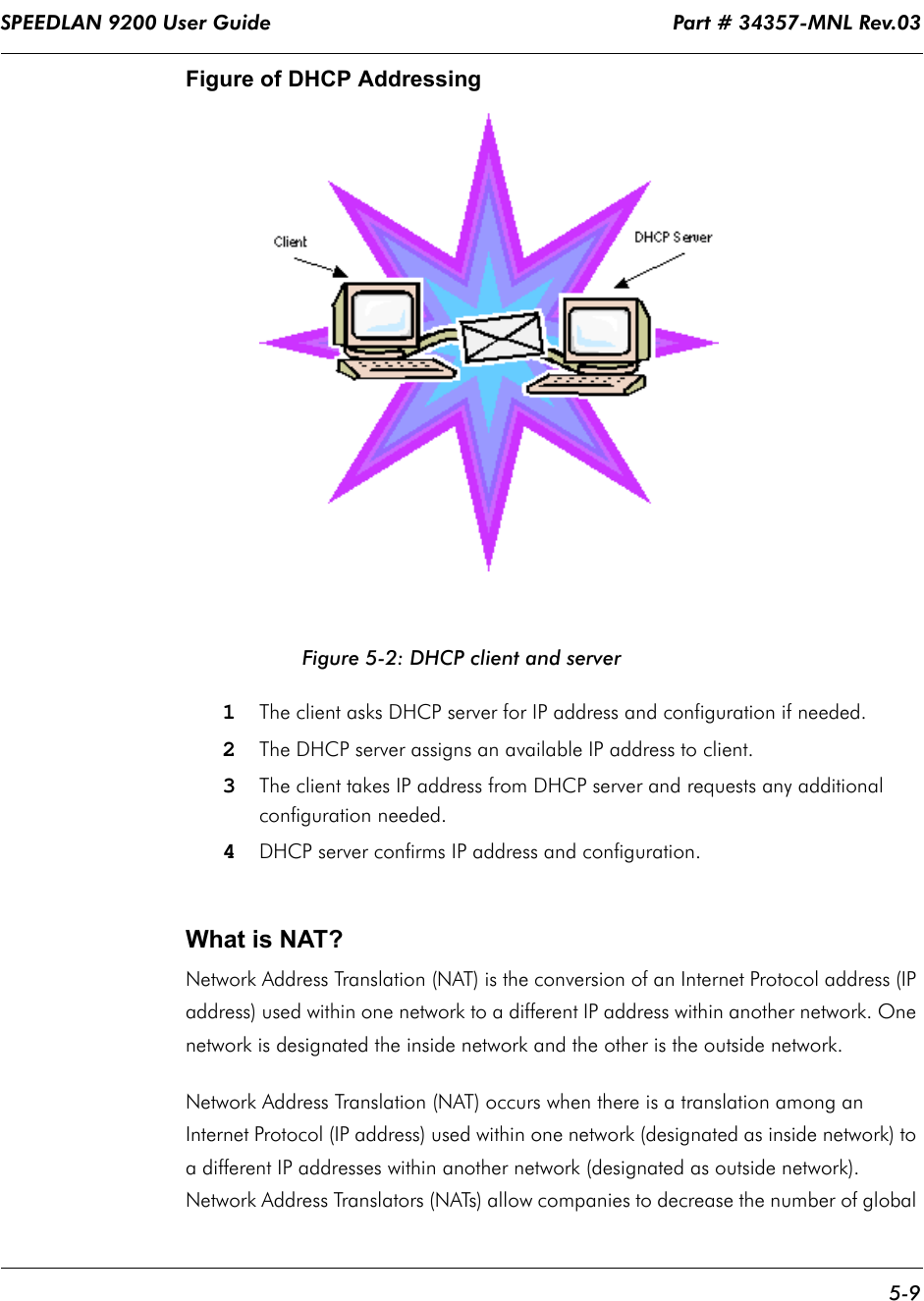
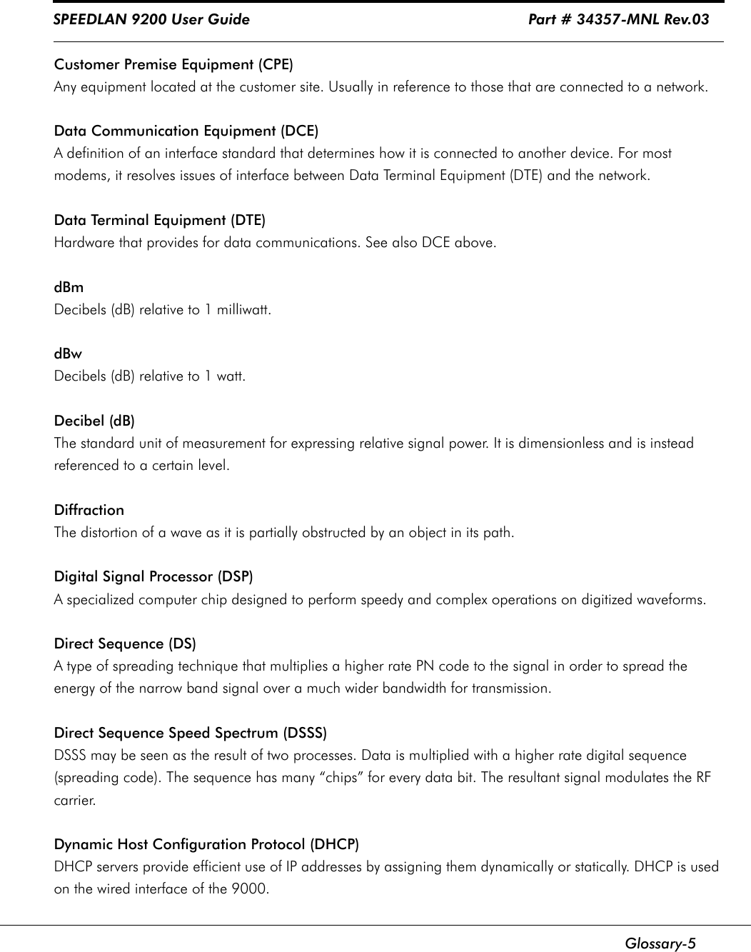
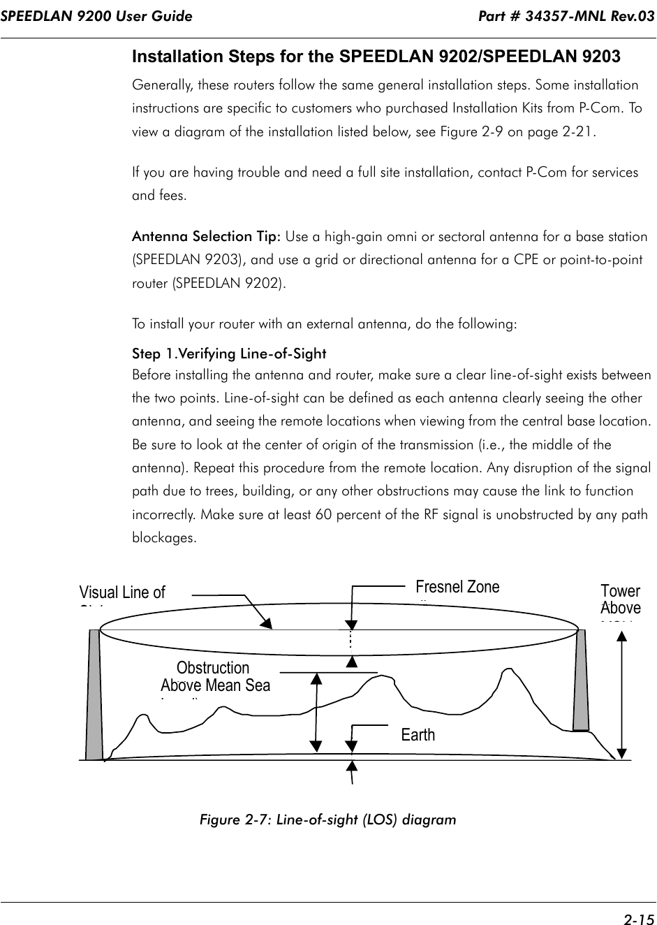
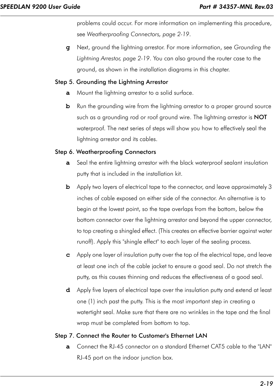
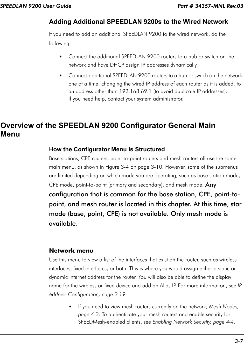
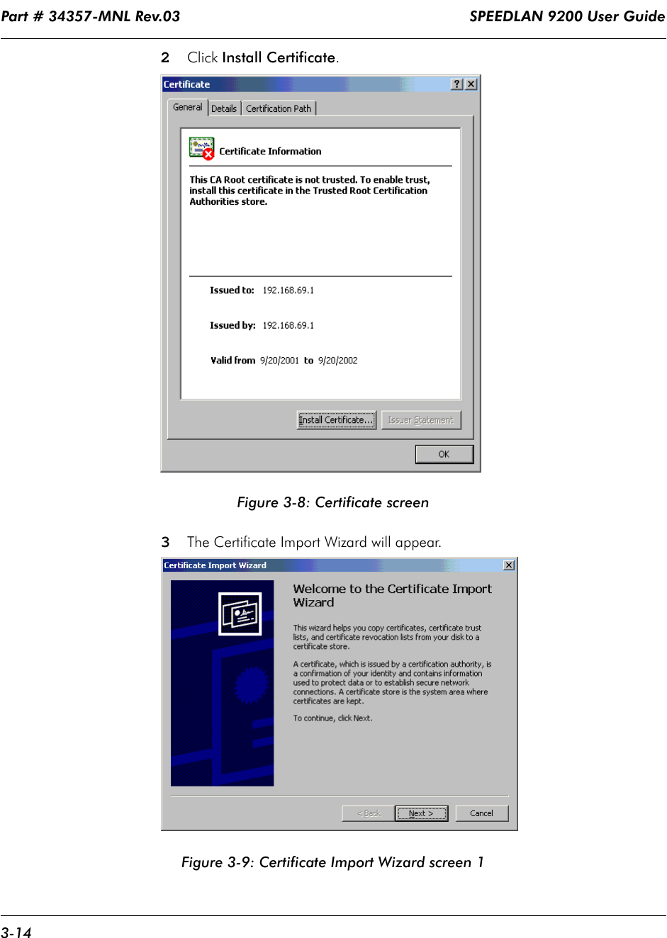
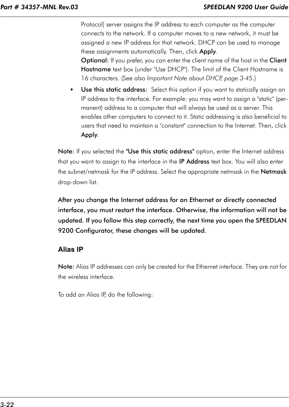
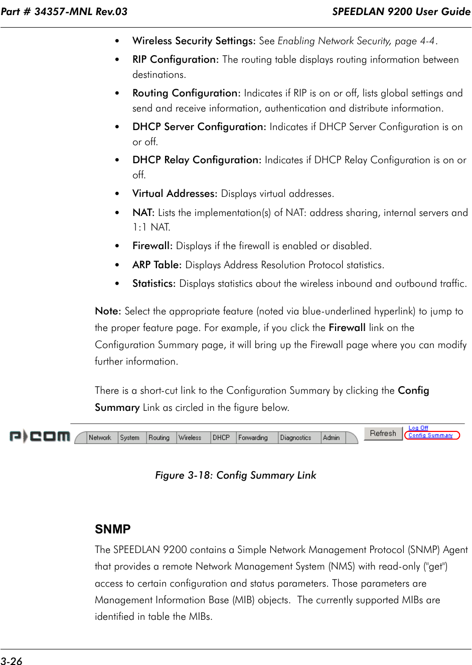
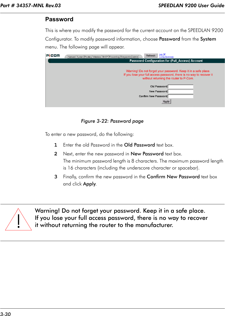
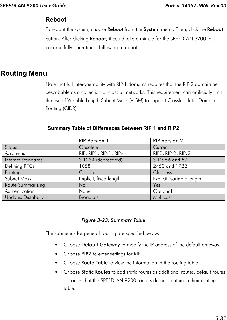
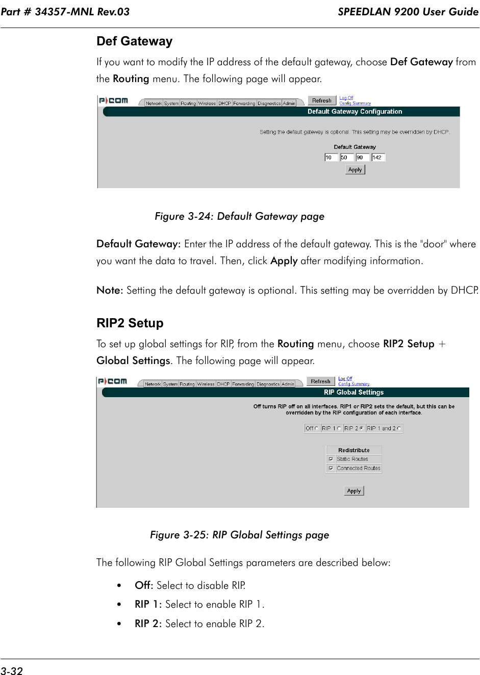
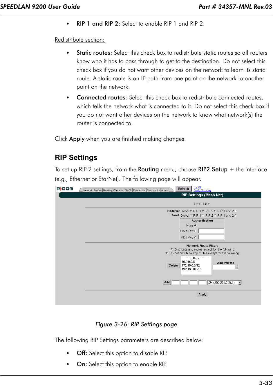
![SPEEDLAN 9200 User Guide Part # 34357-MNL Rev.03 1-7 SPEEDLAN 9200 routers provide the unique ability to "self-heal" the wireless network as the topography changes over time, thereby increasing the overall stability and performance of the network while allowing traffic to reach buildings blocked by obstructions of line-of-sight. What is happening in Figure 1-1 on page 1-6? •You will notice negative numbers next to the routers, or referred to as nodes on the network diagram. These numbers represent the receive signal strength (expressed as dBm) for the links in the network diagram. •The black dots in a mesh network diagram indicate a trace route, which maps out the current data flow between the selected pair of nodes. A user would select the trace feature to view the data flow between a node pair (for mesh networks only). This illustration also shows that every router in the mesh cell can be heard by every other router in the cell, except for the blocked link indicating that there is no signal between those two nodes. SPEEDView allows you to block traffic over any link in the cell. When you block a connection, the node pair will not be able to communicate. The advantage of blocking a connection is verifying that the path can be re-routed for suc-cessful connectivity. (This is done using the "Block" feature in SPEEDView. The broken [or disconnected] link will appear as a red line. This link also appears when there is no signal between two nodes.) •SPEEDView can also be used to perform bandwidth, link and ping tests. Routing Around ObstaclesFigure 1-2: Routing around obstacles Obstacle A E BC D](https://usermanual.wiki/Wave-Wireless/SL9202/User-Guide-479140-Page-15.png)

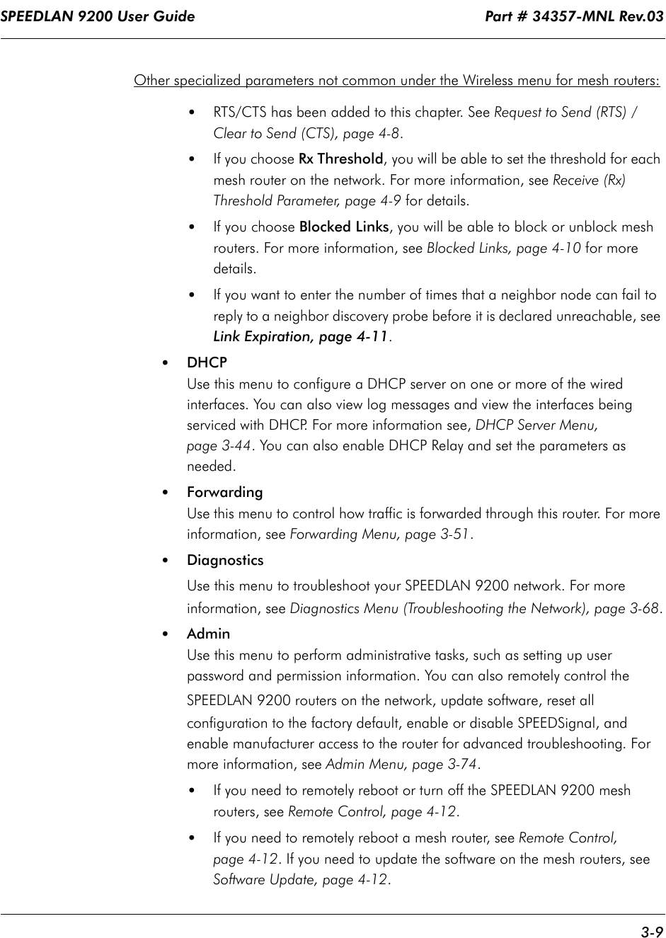
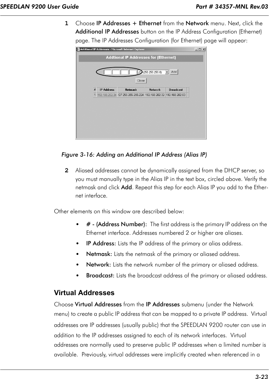
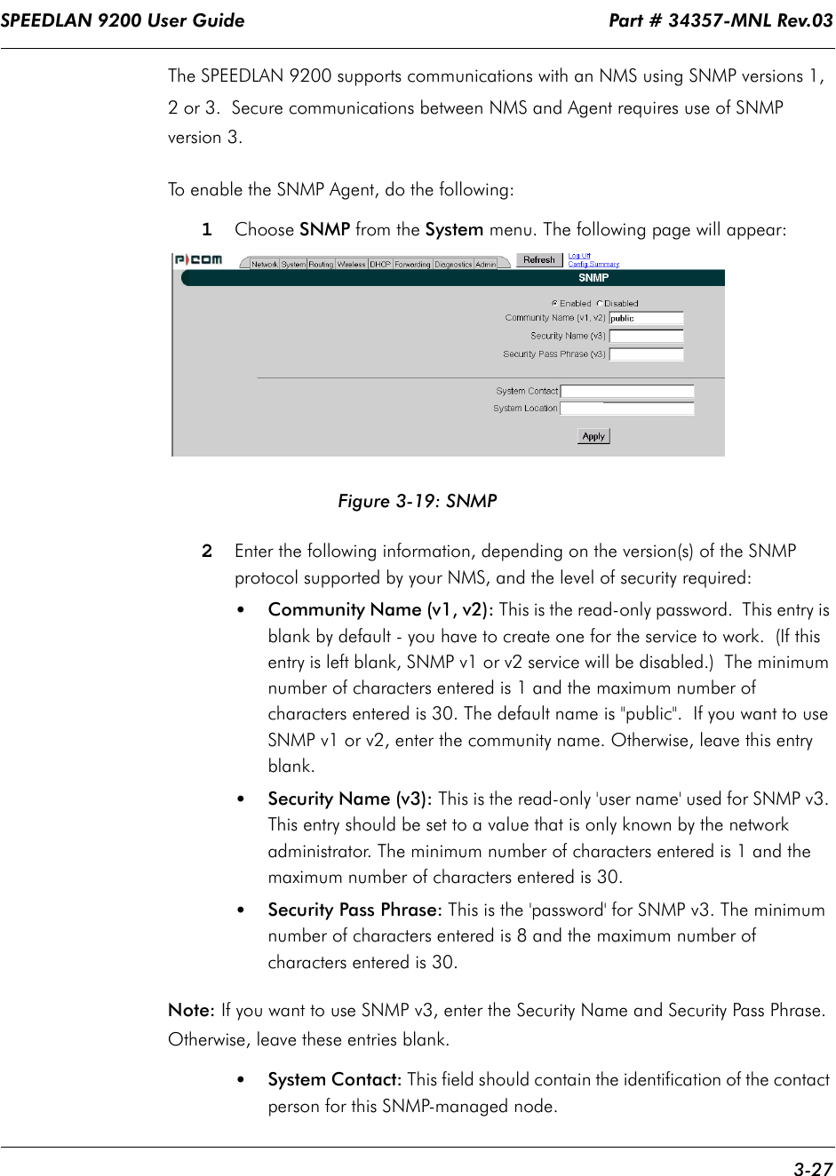
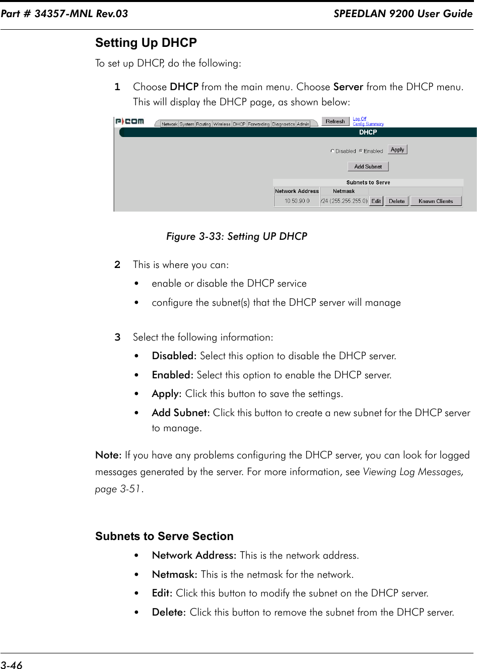
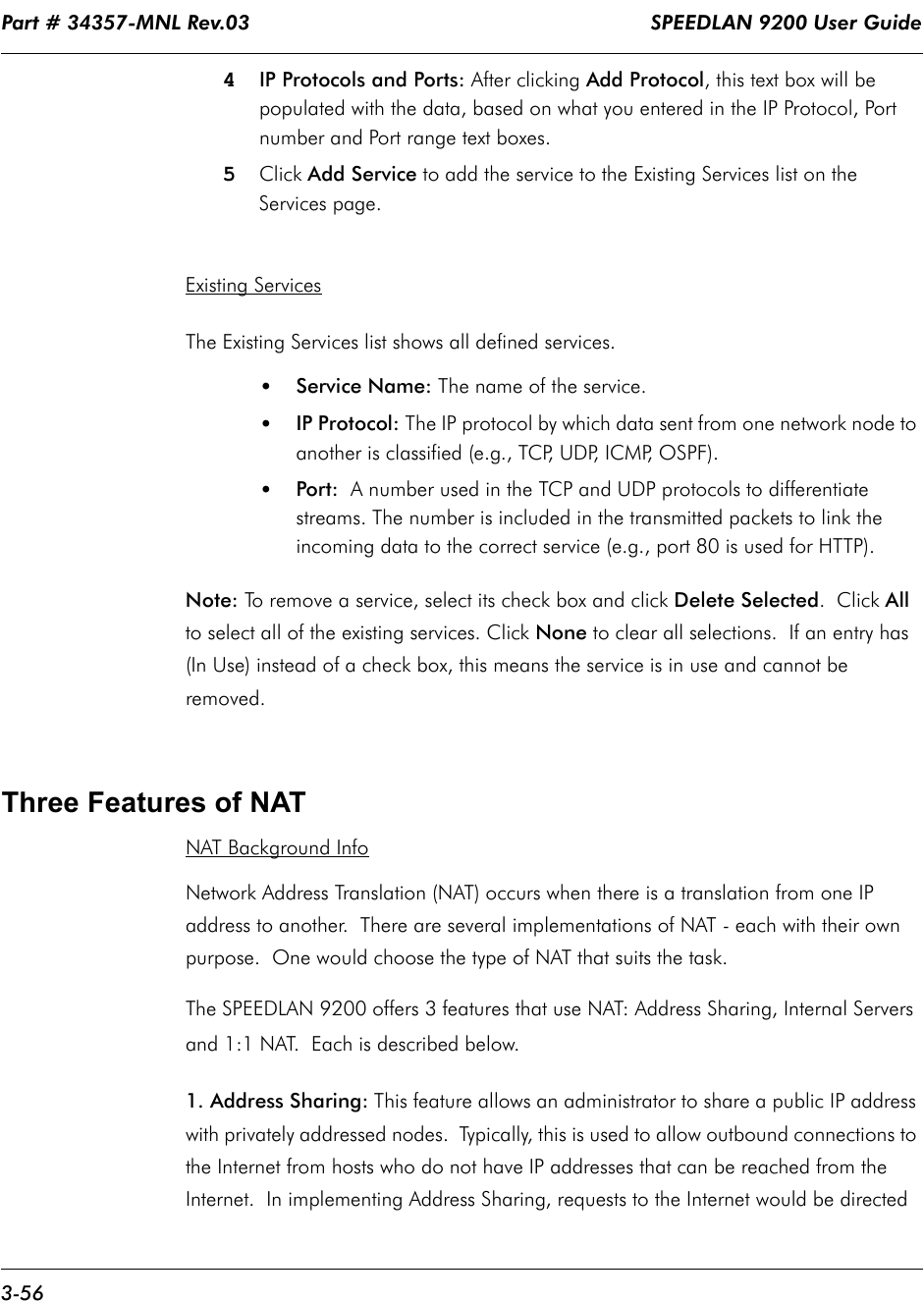
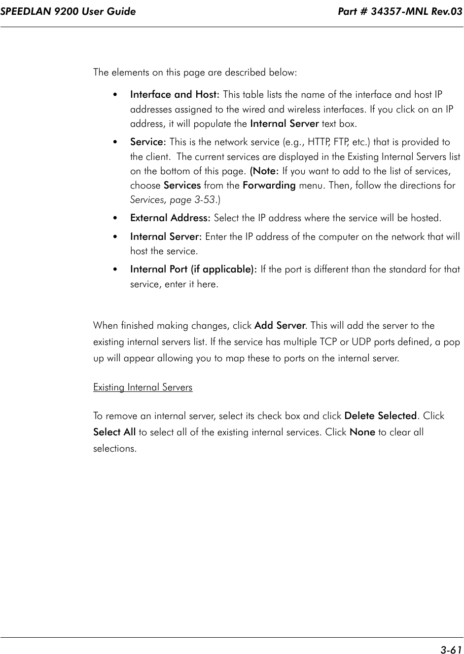
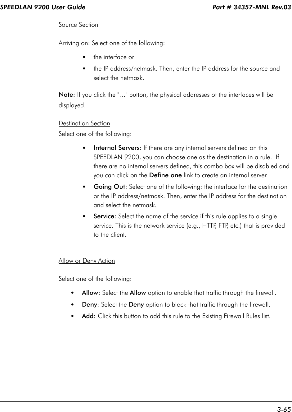
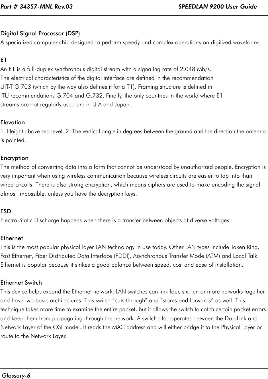
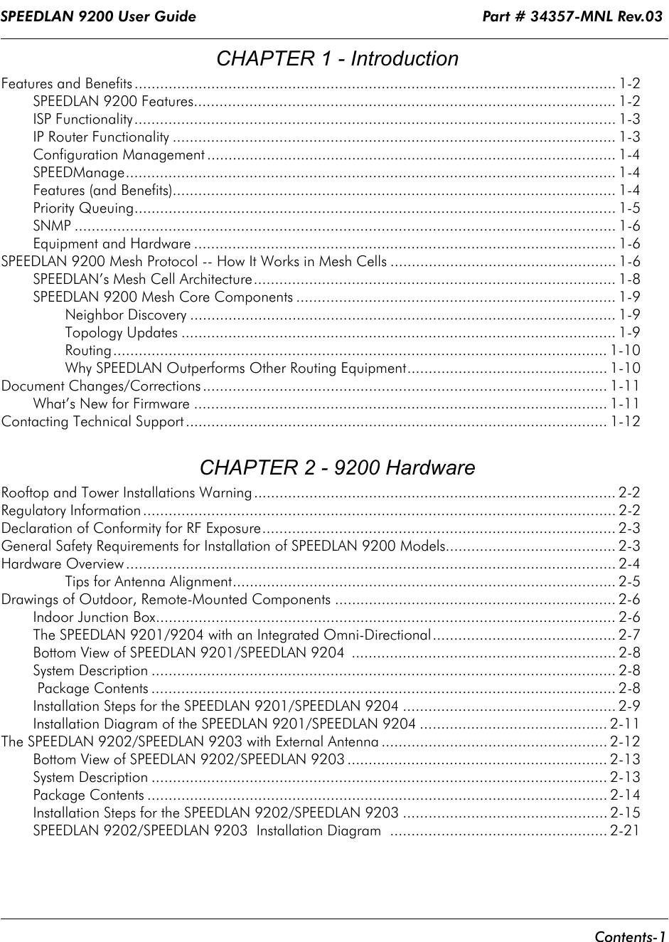
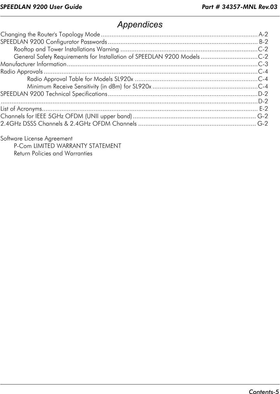
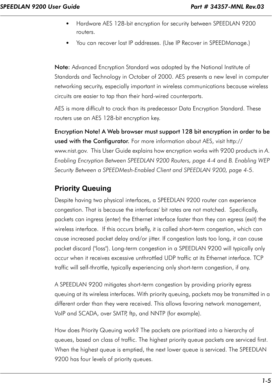
![SPEEDLAN 9200 User Guide Part # 34357-MNL Rev.03 3-55 •Less Common Services: This list contains less common types of network services. Select the appropriate service from this drop-down list. Your selection will be added to the Services page. Then, click the Add Service button on the Services page. Creating an Advanced ServiceIf you cannot locate the service you want to add, you can define an advanced service by clicking the Advanced link to the right of the "Choose" button (as circled in blue in Figure 3-39 on page 3-54). The following pop-up will appear:Figure 3-41: Advanced Services (adding AIM)Advanced services can have one or more IP protocols. Under Advanced Services, you will need to know the name of the service (or it can be unique), the protocol(s) used and the ports needed to operate the service. For the TCP and UDP protocols, you can define specific ports, or a range of ports. Enter the following information:1Service Name: Enter a new name for the service. (In the previous figure, the user entered "AIM" because the user wanted to add AOL Instant Messenger.)2IP Protocol: Select an IP protocol for your service. If you select any protocol other than TCP or UDP, the protocol will be immediately added to the list of protocols for this service. (In previous figure, the user selected "UDP" because it is the protocol for AIM.)3[Port range]: If you select TCP or UDP, you can specify a port or a port range. Then, click Add Protocol to add that protocol and port to the list. Click Clear to remove the IP protocol list if you need to start over. (In the previous figure, the user entered port "5190".) If you are only entering a single port, enter it in the left Port Range text box.](https://usermanual.wiki/Wave-Wireless/SL9202/User-Guide-479140-Page-97.png)