WaveIP WA605X Point-to-Point & Point-to-Multipoint broadband wireless bridge User Manual
WaveIP Ltd. Point-to-Point & Point-to-Multipoint broadband wireless bridge
WaveIP >
User Manual


WaveIP
Ltd.
WipAir 6000/3000 Installation Guide
Page
2
of 32
W
Wi
ip
pA
Ai
ir
r
6
60
00
00
0/
/3
30
00
00
0
I
In
ns
st
ta
al
ll
la
at
ti
io
on
n
a
an
nd
d
O
Op
pe
er
ra
at
ti
io
on
n
I
In
ns
st
tr
ru
uc
ct
ti
io
on
ns
s
October 2009
WaveIP Ltd.
Teradion Industrial Park
Misgav 20179, Israel
Tel: 972-4-902-7000
Fax: 972-4-999-0324
Info@waveip.com
The information contained in this document is of commercial value,
proprietary to WaveIP. It is conveyed to the recipient solely for the
purpose of evaluation. Reproduction of this document, disclosure of its
contents or any other use of the infor
mation herein is strictly forbidden
unless expressly authorized in writing by WaveIP.

WaveIP
Ltd.
WipAir 6000/3000 Installation Guide
Page
3
of 32
N
No
ot
ti
ic
ce
es
s
Radio Frequency Statement
WipAir 6000/3000 has been tested and found to comply with part 15 of the FCC rules
and EN 301 489-1 rules. These limits are designed to provide reasonable protection
against harmful interference when the equipment is operated in a residential
environment notwithstanding use in commercial, business and industrial
environments. Operation is subject to the following two conditions:
(1) This device may not cause harmful interference, and
(2) This device must accept any interference received, including interference that may
cause undesired operation.
IMPORTANT! It is the responsibility of the installer to ensure that when using
the outdoor antenna kits in the United States (or where FCC
rules apply), only those antennas certified with the product are
used. The use of any antenna other than those certified with the
product is expressly forbidden in accordance to FCC rules CFR47
part 15.204.
IMPORTANT! Outdoor units and antennas should be installed ONLY by
experienced installation professionals who are familiar with local
building and safety codes and, wherever applicable, are licensed
by the appropriate government regulatory authorities. Failure to
do so may void the product warranty and may expose the end
user or the service provider to legal and financial liabilities.
WaveIP and its resellers or distributors of this equipment are not
liable for injury, damage or violation of regulations associated
with the installation of outdoor units or antennas.
R&TTE Declaration on Conformity
Hereby, WaveIP Ltd, declares that WipAir 6000/3000 is in compliance
with the essential requirements and other relevant provisions of
Directive 1999/5/EC. The declaration of conformity may be consulted
through WaveIP Ltd., Teradion Industrial Park, Misgav 20179, Israel.
Compliance with European Union WEEE Directives
In January 2003, the European Union adopted an important environmental directive -
- the Directive on Waste Electrical and Electronic Equipment (WEEE). It represents an
important milestone in providing a safer environment for future generations.
The WEEE label and instructions for disposal are as follows:

WaveIP
Ltd.
WipAir 6000/3000 Installation Guide
Page
4
of 32
Instructions for Disposal of Waste Equipment by Users in the European Union
This symbol on the product or its packaging indicates that this product
must not be disposed of with other waste. Instead, it is your
responsibility to dispose of your waste equipment by handing it over to
a designated collection point for the recycling of waste electrical and
electronic equipment. The separate collection and recycling of your
waste equipment at the time of disposal will help conserve natural
resources and ensure that it is recycled in a manner that protects
human health and the environment. For more information about where
you can drop off your waste equipment for recycling, please contact WaveIP.
Warranty
WaveIP warrants that this product shall be free from defects in workmanship and
materials for a period of one year from the date of original purchase. If the product
should fail to operate correctly in normal use during the warranty period, WaveIP will
replace or repair it free of charge. No liability can be accepted for damage due to
misuse or circumstances outside WaveIP’s control. WaveIP will not be responsible for
any loss, damage or injury arising directly or indirectly from the use of this product.
WaveIP’s total liability under the terms of this warranty shall in all circumstances be
limited to the replacement value of this product.
If any difficulty is experienced in the installation or use of this product that you are
unable to resolve, please contact WaveIP.

WaveIP
Ltd.
WipAir 6000/3000 Installation Guide
Page
5
of 32
T
TA
AB
BL
LE
E
O
OF
F
C
CO
ON
NT
TE
EN
NT
TS
S
NOTICES ........................................................................................................ 3
1.
INTRODUCTION..................................................................................... 7
1.1
A
PPLICATIONS
...........................................................................................7
1.2
T
ECHNICAL OVERVIEW
.................................................................................8
1.3
E
LEMENT
M
ANAGEMENT
S
YSTEM
....................................................................12
1.3.1 NMS.................................................................................................12
1.3.2 Link Manager ....................................................................................12
1.3.3 Standard Protocols.............................................................................14
2.
INSTALLATION .................................................................................... 15
2.1
P
ACKING
L
IST
.........................................................................................15
2.2
A
DDITIONAL
P
ART
L
IST
– R
EQUIRED FOR
I
NSTALLATION
.......................................15
2.3
I
NSTALLATION
O
VERVIEW
...........................................................................16
2.3.1 Select the Best Location .....................................................................17
2.3.2 Mounting ..........................................................................................18
2.3.3 Antennas ..........................................................................................18
2.3.4 Alignment .........................................................................................20
2.3.5 Sealing.............................................................................................21
2.3.6 Cables..............................................................................................22
2.3.7 Indoor Outlet Installation....................................................................24
2.3.8 Grounding.........................................................................................25
2.4
C
ONSECUTIVE
AP C
ONNECTION
....................................................................26
2.5
S
YNCHRONIZATION
...................................................................................27
3.
WIPAIR 6000 TECHNICAL SPECIFICATIONS ....................................... 28
3.1
R
ADIO
..................................................................................................28
3.2
N
ETWORKING AND
M
ANAGEMENT
...................................................................28
3.3
P
HYSICAL AND
E
NVIRONMENTAL
....................................................................28
4.
WIPAIR 3000 TECHNICAL SPECIFICATIONS ....................................... 29
4.1
R
ADIO
..................................................................................................29
4.2
N
ETWORKING AND
M
ANAGEMENT
...................................................................29
4.3
P
HYSICAL AND
E
NVIRONMENTAL
....................................................................29
5.
APPENDIX A – OUTDOOR CABLES SCHEME .......................................... 30
6.
APPENDIX B – RF CHANNEL LISTS ...................................................... 31
6.1
FCC
OPERATING
B
AND
: 5725 MH
Z
- 5850 MH
Z
. ............................................31
7.
APPENDIX C – FCC APPROVED ANTENNAS .......................................... 32

WaveIP
Ltd.
WipAir 6000/3000 Installation Guide
Page
6
of 32
T
TA
AB
BL
LE
E
O
OF
F
F
FI
IG
GU
UR
RE
ES
S
Figure
1-1: WipAir 6000/3000 PTP (blue) and PTMP (red).......................................7
Figure
1-2: WipAir 6000 2x2 dual polarization MIMO..............................................8
Figure
1-3: Automatic interference sensibility........................................................9
Figure
1-4: Multiple WipAir 6000/3000 MUs on one tower.....................................10
Figure
1-5: Self-interference without time synchronization ...................................10
Figure
1-6: Time synchronization eliminates self-interference ...............................10
Figure
1-7: Consecutive AP™ principle ...............................................................11
Figure
1-8: WIPview ........................................................................................12
Figure
1-9: Link Manager .................................................................................13
Figure
1-10: Built in RF analyzer and throughput test tool ....................................13
Figure
1-11: WEB interface ...............................................................................14
Figure
2-1: General System View ......................................................................15
Figure
2-2: WipAir 6000/3000 - General Installation Scheme ................................16
Figure
2-3: Wall mount description ....................................................................18
Figure
2-4: Cable preparation for Outdoor Unit...................................................22
Figure
2-5: Cable assembly to Outdoor Unit........................................................23
Figure
2-6: Cable insertion to Outdoor Unit.........................................................23
Figure
2-7: Cable connection to Outdoor Unit.....................................................23
Figure
2-8: Indoor Outlet ................................................................................24
Figure
2-9: Ground Connection to Outdoor Unit...................................................25
Figure
2-10: Consecutive link principle ...............................................................26
Figure
5-1: Outdoor Cables Scheme...................................................................30
Figure
6-1: RF channel List ...............................................................................31
Figure
7-1: Integrated / external antennas for WipAir 6000/3000..........................32
WaveIP
Ltd.
WipAir 6000/3000 Installation Guide
Page
7
of 32
1
1.
.
I
In
nt
tr
ro
od
du
uc
ct
ti
io
on
n
Thank you for purchasing WipAir 6000/3000 point-to-point solution. WipAir
6000/3000 is a carrier grade, the best of its class point-to-point and Point-to-
multipoint broadband wireless bridge. WipAir 6000/3000 is the next generation of
radio technology with field proven features of WipAirII. WipAir 6000/3000
comprises of Reliability, High Capacity, Lowest Latency, RF Robustness, Rugged
outdoor design, Flexibility and Simplicity to install and maintain.
1
1.
.1
1
A
Ap
pp
pl
li
ic
ca
at
ti
io
on
ns
s
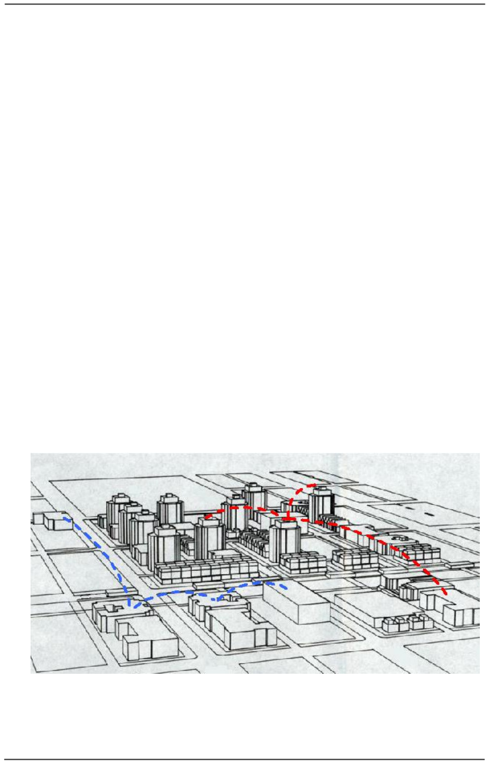
Point-to-Point (PTP):
The basic subsystem is composed of a Master Unit (MU) and a Slave Unit (SU).
Typical applications:
• IP data backhaul of:
o WiMAX operators
o Metro WiFi Networks
o Cellular and 3G
• Backhaul of video surveillance systems
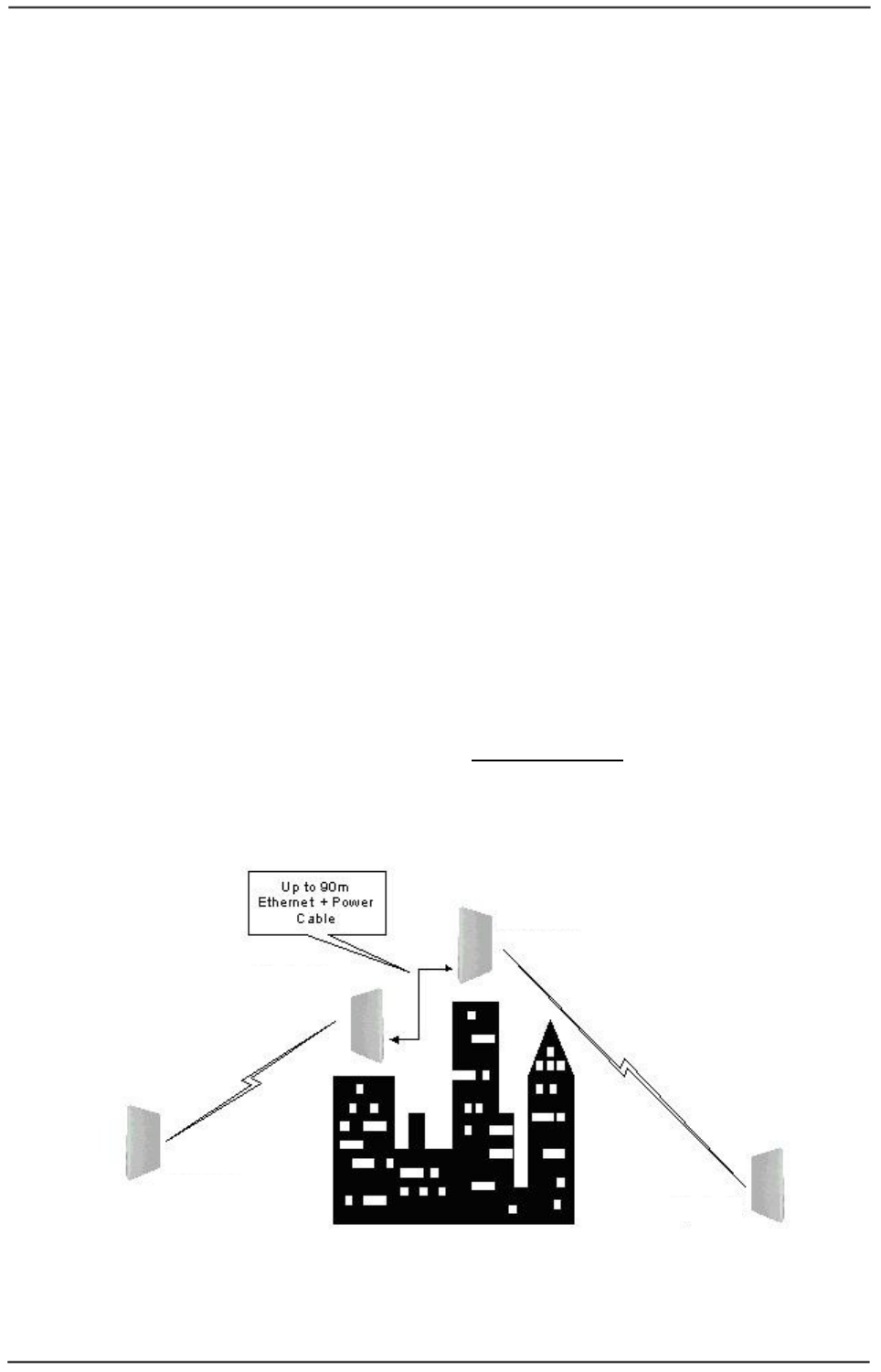
Point-to-Multipoint (PTMP):
The basic subsystem is composed of the same Master Unit (MU) and multiple Slave
Units (SUs). Typical applications:
• Multiple backhauls solutions
• Multiple Video surveillance systems
• High bandwidth campus solutions
Figure
1-1: WipAir 6000/3000 PTP (blue) and PTMP (red)
WaveIP
Ltd.
WipAir 6000/3000 Installation Guide
Page
8
of 32
1
1.
.2
2
T
Te
ec
ch
hn
ni
ic
ca
al
l
o
ov
ve
er
rv
vi
ie
ew
w
WipAir 6000/3000 introduces unmatched benchmark of features and built in
technological advantages:
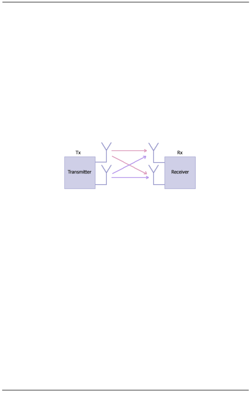
• Advanced OFDM 2x2 MIMO - Utilizing superior Advanced OFDM 2x2 dual
polarization MIMO (Multiple Input Multiple Output), WipAir 6000 provides
cutting edge advantages:
o Higher capacity and spectral efficiency - 100 Mbps full duplex. 2x2
MIMO transmits 2 streams that double the throughput on same channel
bandwidth.
o Long range - MIMO can deliver same throughput by transmitting 2
lower rate streams, achieving
sustained throughput over long distances
.
o Increased reliability and availability - transmitting 2 lower rate streams
provides higher fade margin, increasing reliability and link’s availability.
Figure
1-2: WipAir 6000 2x2 dual polarization MIMO
• High capacity – up to 100 Mbps full duplex net throughput.
• Best latency - 1msec typical (PTP). Ideal for backhaul, multi-hop backhauls
and voice, video & interactive applications.
• More than 50,000 PPS (Packets Per Second) – ideal for VOIP backhaul
applications
• Superior 7.5 bit/Hz spectral efficiency – 300 Mbps over 40 MHz channel
via:
o 2x2 dual polarization MIMO
o Advanced OFDM:
• Higher number of OFDM Subcarriers.
• Reduced guard interval.
o Forward Error Correction of 5/6 @ 64QAM
• Symmetric / dynamic throughput - up/downstream throughput can be
symmetric or dynamic & automatic according to the actual traffic, optimizing
the link to the application.

WaveIP
Ltd.
WipAir 6000/3000 Installation Guide
Page
9
of 32
• Output Power - High dynamic range of 40 dB up to 26 dBm.
• Versatile radio – increase flexibility and scalability:
o Configurable channel bandwidth (5/10/20/40 MHz) maximizes capacity
and availability.
o Multiple frequency bands in one radio.
• RF and interference robustness - WipAir 6000/3000 introduces unique and
robust interference mitigation mechanisms:
o Automatic Interference Sensibility - proprietary solution that
increases RF robustness by eliminating false receptions of noise thus
maintaining constant throughput and latency. The automatic sensibility
sets an Rx threshold above the noise level as shown in figure 3.
o ACM - Adaptive Modulation and Coding (modulation can be defined
manually as well).
o FEC - Forward Error Correction, K = 1/2, 2/3, 3/4, 5/6.
o Fast ARQ - Automatic Retransmit reQuest.
Figure
1-3: Automatic interference sensibility
• 128-bit AES encryption – non-compromising security.
• Networking and QoS – built in QoS in both PTP and PTMP modes:
o Bandwidth control – define maximum throughput for each direction
(uplink and downlink) independently.
o 8 priority queues – packets are classified according to TOS and VLAN
priority into the queues (7 = highest priority and 0 = lowest priority).
o Packet filtering: VLAN based and broadcast filters.
o VLAN tagging/stripping per terminal.
• Real time synchronization - by GPS or internal. WipAir 6000/3000 built in
time synchronization technology allows collocation of multiple MUs on the
same tower and on collocated towers while reusing frequencies, eliminating
self-interference between them.
Signal RSSI
Rx Sensitivity
Noise
SNR
Rx Threshold
WaveIP
Ltd.
WipAir 6000/3000 Installation Guide
Page
10
of 32
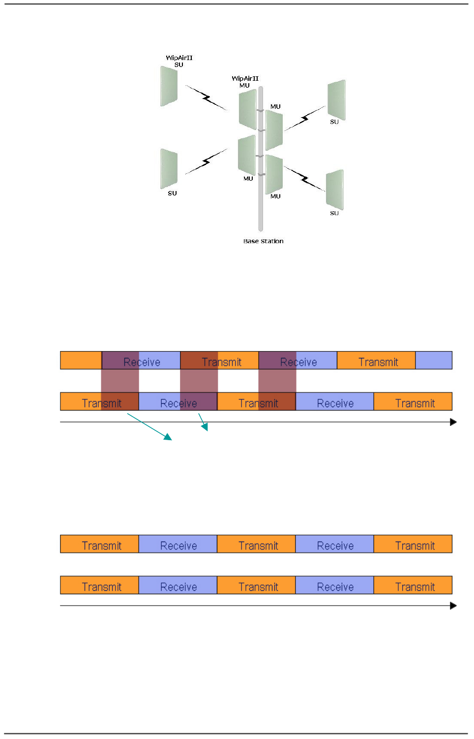
Figure
1-4: Multiple WipAir 6000/3000 MUs on one tower
Without time synchronization, one MU will transmit while the other MU receives. The
transmittion of the first MU will block the reception of the second MU since they are
close to each other (can even occur when the MUs are on different channels).
Figure
1-5: Self-interference without time synchronization
Time synchronization synchronizes the transmission and reception of all MUs, thus
eliminating self interference between them and allowing better frequency reuse.
Figure
1-6: Time synchronization eliminates self-interference
T (msec)
Collisions
MU 1
MU 2
T (msec)
MU 1
MU 2
WaveIP
Ltd.
WipAir 6000/3000 Installation Guide
Page
11
of 32
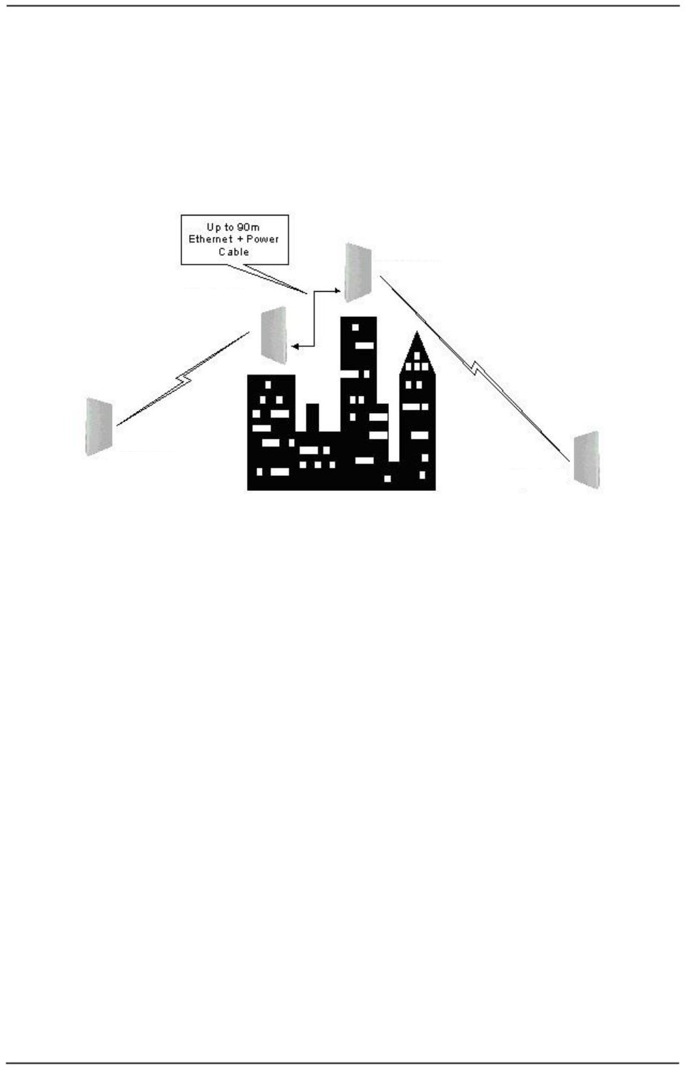
• Built in redundancy -
o Power & data redundancy via 2xRJ-45.
o 1+1 trunking capability.
o Consecutive AP™ - concatenation capability with power redundancy,
as shown in figure 7.
Figure
1-7: Consecutive AP™ principle
• Lowest total cost of ownership - Engineered for affordability, WipAir
6000/3000 empowers operators with extremely low CAPEX & OPEX:
o Most competitive price
o Rugged & reliable weather proof design
o Compact and very simple to install:
• Fast installation by 1 technician.
• Built in RSSI buzzer for easy alignment.
• Built in RF analyzer - simplest site survey tool.
• ACS – Automatic Channel Selection (automatic site survey).
• Extremely low power consumption: < 6Watt.
o Multiple frequency bands in one radio – ease of stocking and
maintenance.
o Over the air remote management
WipAir MU
WipAir SU
WipAir MU
WipAir SU

WaveIP
Ltd.
WipAir 6000/3000 Installation Guide
Page
12
of 32
1
1.
.3
3
E
El
le
em
me
en
nt
t
M
Ma
an
na
ag
ge
em
me
en
nt
t
S
Sy
ys
st
te
em
m
WipAir 6000/3000 is managed in three ways:
1
1.
.3
3.
.1
1
N
NM
MS
S
As part of a deployment, The Network Management system (ViewAir NMS) provides
one point of management for all the links deployed and allows the operator to monitor
and control the units:
• Managing entire deployment composed of WipAir Radios
• Radio link monitoring and configuration.
• Easy PTMP configuration – all in one point.
• System health in a glance.
• Multiple networking modes under single MU.
Figure
1-8: WIPview
1
1.
.3
3.
.2
2
L
Li
in
nk
k
M
Ma
an
na
ag
ge
er
r
In a technician level, The Element Management System (Link Manager) provides a
complete GUI system to configure/monitor the radio.
The Link Manager automatically connects to the radio (from either side), discovers the
radio and allows the technician to configure and monitor the radio with WYSIYG
application.
WaveIP
Ltd.
WipAir 6000/3000 Installation Guide
Page
13
of 32
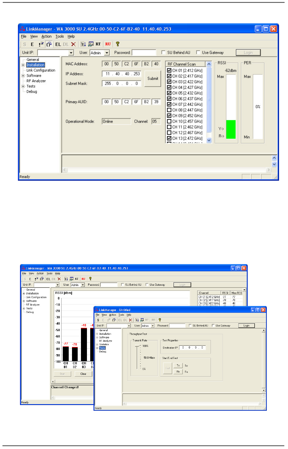
Figure
1-9: Link Manager
The Link Manager contains a built in:
• RF analyzer.
• Numerous link indicators and counters.
• Traffic generator – throughput test tool.
Figure
1-10: Built in RF analyzer and throughput test tool
WaveIP
Ltd.
WipAir 6000/3000 Installation Guide
Page
14
of 32
1
1.
.3
3.
.3
3
S
St
ta
an
nd
da
ar
rd
d
P
Pr
ro
ot
to
oc
co
ol
ls
s
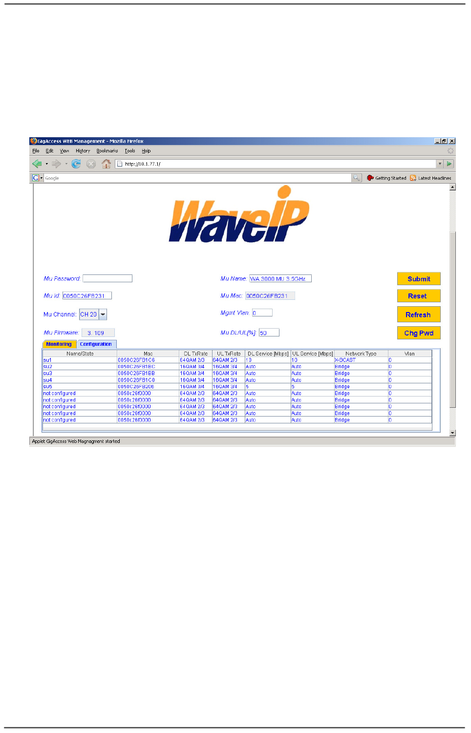
WipAir 6000/3000 supports the following protocols:
• WEB (HTTP) – Manage the radio using an Internet browser.
• SNMP – Supports v2c with a private MIB, Traps and notifications.
• Telnet.
Figure
1-11: WEB interface
WaveIP
Ltd.
WipAir 6000/3000 Installation Guide
Page
15
of 32
1
2
3
4
2
2.
.
I
In
ns
st
ta
al
ll
la
at
ti
io
on
n
2
2.
.1
1
P
Pa
ac
ck
ki
in
ng
g
L
Li
is
st
t
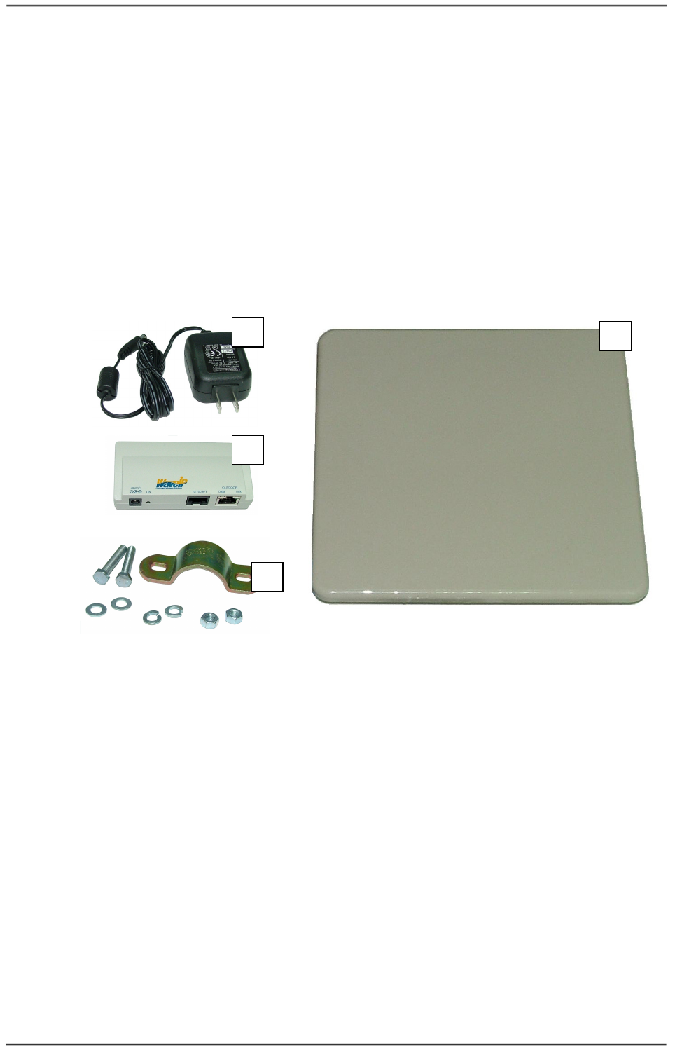
When you first open the package, verify that the unit is complete with the following
components:
1. Outdoor Unit – WipAir 6000/3000 MU or SU.
2. Indoor PoE Outlet.
3. Indoor Power Supply (AC input).
4. Pole mounting kit (will not be added if advanced mounting kit is provided).
Figure
2-1: General System View
2
2.
.2
2
A
Ad
dd
di
it
ti
io
on
na
al
l
P
Pa
ar
rt
t
L
Li
is
st
t
–
–
R
Re
eq
qu
ui
ir
re
ed
d
f
fo
or
r
I
In
ns
st
ta
al
ll
la
at
ti
io
on
n
• Outdoor Unit grounding cable
• Outdoor-to-Indoor shielded CAT5 cable (Up to 90 meters).
• Indoor CAT5 cable.
• RJ-45 - Installation KIT.
• RJ-45 - Crimping tool.
• Adjustable wrench + screwdriver.
WaveIP
Ltd.
WipAir 6000/3000 Installation Guide
Page
16
of 32
2
2.
.3
3
I
In
ns
st
ta
al
ll
la
at
ti
io
on
n
O
Ov
ve
er
rv
vi
ie
ew
w
This section provides installation information for WipAir 6000/3000 system.
Note
:
Outdoor units and antennas should be installed ONLY by experienced
installation professionals who are familiar with local building and safety
codes and, wherever applicable, are licensed by the appropriate government
regulatory authorities. Failure to do so may void the product warranty and
may expose the end user or the service provider to legal and financial
liabilities. WaveIP and its resellers or distributors of this equipment are not
liable for injury, damage or violation of regulations associated with the
installation of outdoor units or antennas.
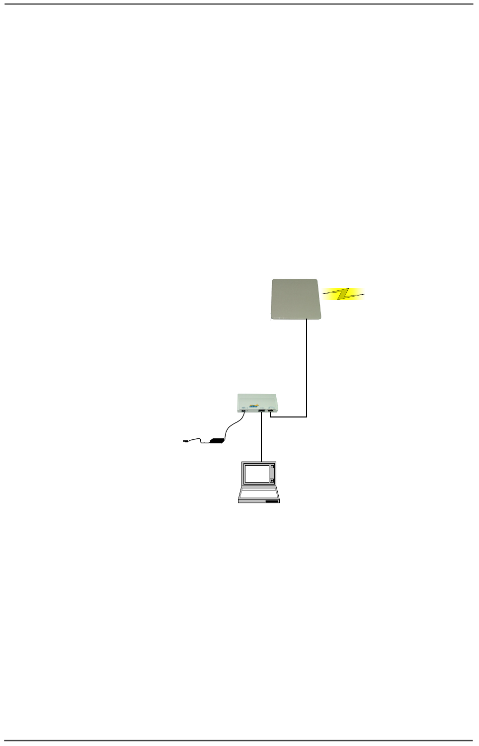
Typical installation scheme:
WipAir - Outdoor Unit
with integrated Antenna
Outdoor to
Indoor CAT5
Indoor Outlet
User computer
Indoor CAT5
Power
Supply
100-240V
AC
Figure
2-2: WipAir 6000/3000 - General Installation Scheme
Installation process summary:
1) Select the appropriate location for the Outdoor unit and the indoor PoE Outlet.
2) Mount the Outdoor unit. If you are using detached antenna mount the antenna
and connect it to the Outdoor unit.
3) Connect a ground cable between the Outdoor unit and an appropriate
grounding point.
4) Connect the Outdoor-to-Indoor shielded CAT5 cable to the Outdoor unit and
route it to the location selected for the PoE Outlet. Assemble the enclosed
connector on the cable.
5) Mount the Indoor Outlet.
6) Connect the Outdoor-to-Indoor cable to the PoE Outlet ‘OUTDOOR’ port. (This
port supplies 48 VDC in addition to the Ethernet data).

WaveIP
Ltd.
WipAir 6000/3000 Installation Guide
Page
17
of 32
7) Connect the CAT5 Ethernet cable from the user’s network/PC to the PoE Outlet
‘10/100 B-T’ port.
8) Connect the power supply to the PoE Outlet power port (‘48VDC’).
9) Align the antenna and secure the unit by fastening the mounting screws.
2
2.
.3
3.
.1
1
S
Se
el
le
ec
ct
t
t
th
he
e
B
Be
es
st
t
L
Lo
oc
ca
at
ti
io
on
n
Select the appropriate locations for the outdoor unit using the following guidelines:
• The outdoor unit can be pole or wall mounted.
• The location should allow easy access to the unit for installation.
• When using an external antenna, the unit should be installed as near as
possible to the antenna.
• Make sure clear Line of Sight between the units.
Path of Clearest Propagation
A propagation path is the path that signals traverse between the antennas of any two
bridges. The “line” between two antenna sites is an imaginary straight line, which
may be drawn between the two antennas. Any obstacles in the path of the “line”
degrade the propagation path. The best propagation path is, therefore, a clear line of
sight with good clearance between the “line” and any physical obstacle.
Physical Obstacles
Any physical object in the path between MU and SU can cause signal attenuation.
Common obstructions are buildings, trees and hills located in the path between the
two sites. Install outdoor antennas high enough to avoid any obstacles, which may
block the signal.
Minimal Path Loss
Path loss is determined by several factors:
• Distance between sites – Path loss is lower when distances between sites
are shorter.
• Clearance – Path loss is minimized when there is a clear line of sight. The
number, location, and size of obstacles determine their contribution to path
loss.
• Antenna height – Path loss is lower when antennas are positioned higher.
Antenna height is the distance from the imaginary line connecting the
antennas at the two sites to “ground” level. “Ground” level in an open area is
the actual ground. In dense urban areas, “ground” level is the average height
of the buildings between the antenna sites.
WaveIP
Ltd.
WipAir 6000/3000 Installation Guide
Page
18
of 32
2
2.
.3
3.
.2
2
M
Mo
ou
un
nt
ti
in
ng
g
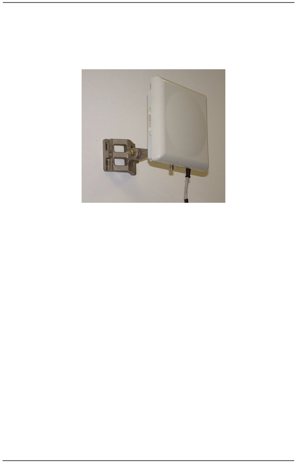
Outdoor Unit can be mount on a pole or on a wall.
A general description of wall mount is given in Figure
2-3.
Figure
2-3: Wall mount description
Note: all outdoor units must be installed with a separation distance of at least
2.5 meters from all persons during normal operation.
2
2.
.3
3.
.3
3
A
An
nt
te
en
nn
na
as
s
2
2.
.3
3.
.3
3.
.1
1
G
Ge
en
ne
er
ra
al
l
Two types of antennas are available for WipAir 6000/3000 system:
• Integrated antenna
• External antenna
The necessary antenna gain depends on the required range and performance.
Note: To comply with the regulation EIRP limits, the outdoor unit-transmit
power needs to be adjusted according to the installed antenna gain.
Therefore a professional installation of the transmitter is required. The
outdoor unit must be configured at the time of installation by qualified
personal. Fail to comply with regulation rules may expose the installer
to legal liabilities.

WaveIP
Ltd.
WipAir 6000/3000 Installation Guide
Page
19
of 32
2
2.
.3
3.
.3
3.
.2
2
T
Tx
x
p
po
ow
we
er
r
The outdoor unit transmit power is configurable using the Link Manager. The Link
Manager limits the max transmit power according to the antenna gain, the regulation
and the frequency band. The installer, if needed, can select a lower power.
Regulation of the unit defines the frequency band supported by the units:
FCC: 5.8 GHz.
ETSI: 5.4 GHz and 5.8 GHz.
Non-regulated: 5.x GHz.
The Link Manager supports two levels of privilege password: regular user and
administrator user. Since power output levels will affect compliance of the unit with
regulation rules, precautions are built into the system to keep the end user from
adjusting the power output level above the regulation limits. Therefore, the following
parameters are Configurable only by administrator user:
• Antenna gain.
• Tx Power.
Please refer to WipAir_6000_3000_configuration_manual.pdf for more information.
FCC - 5.8 GHz
IMPORTANT! Antennas must be selected from a list of WaveIP approved
antennas. Please refer to Appendix C – FCC Approved Antennas.
It is the responsibility of the installer to ensure that when using
the outdoor antenna kits in the United States (or where FCC
rules apply), only those antennas certified with the product are
used. The use of any antenna other than those certified with the
product is expressly forbidden in accordance to FCC rules CFR47
part 15.204.
According to FCC part 15.247(b):
(1) The maximum peak output power of intentional radiator shall not exceed 1 Watt
(+30 dBm).
(3) If transmitting antennas of directional gain greater than 6 dBi are used, the peak
output power from the intentional radiator shall be reduced below the maximum peak
power (of +30 dBm) as appropriate, by the amount in dB that the directional gain of
antenna exceeds 6 dBi.
That is to say that the maximum EIRP (Effective Isotropic Radiated Power) shall not
exceed +36 dBm.
(ii) Systems operating in 5.8 GHz exclusively for fixed, point-to-point operations
may employ transmitting antennas with directional gain greater than 6 dBi without
any corresponding reduction in transmitter peak output power.
That is to say that the maximum EIRP can exceed +36 dBm in point-to-point
applications.
Dynamic range of Tx power in WipAir 6000/3000 is 40 dB.

WaveIP
Ltd.
WipAir 6000/3000 Installation Guide
Page
20
of 32
In Point-to-Multipoint mode, the Link Manager software will automatically reduce the
Tx power according to the antenna gain. For example:
• For integrated antenna of 23 dBi, the Max Tx power allowed by the Link
Manager is 13 dBm (10 dBm in WipAir 6000) to meet the EIRP limitation of 36
dBm.
• For integrated antenna of 28.5 dBi, the Max Tx power allowed by the Link
Manager is 7 dBm (4 dBm in WipAir 6000) to meet the EIRP limitation of 36
dBm.
2
2.
.3
3.
.3
3.
.3
3
A
An
nt
te
en
nn
na
a
P
Po
ol
la
ar
ri
iz
za
at
ti
io
on
n
The MU and SU must have same antenna polarization. To verify antenna polarization,
refer to the assembly instructions supplied with the antenna set. (The polarization of
integrated antenna is marked on the backside).
2
2.
.3
3.
.4
4
A
Al
li
ig
gn
nm
me
en
nt
t
Power up the unit:
1. Plug the AC/DC Power Supply into a wall outlet or other standard AC power
source. This is only for use prior to permanent mounting, so any available wall
outlet in close proximity to your mounting location is suitable.
2. Connect the Outdoor-to-Indoor cable to the PoE Outlet ‘OUTDOOR’ port. (This
port supplies 48 VDC in addition to the Ethernet data).
3. Plug the DC plug from the AC/DC power supply to the DC jack marked
“48VDC”.
WipAir 6000/3000 can be aligned using 2 methods:
2
2.
.3
3.
.4
4.
.1
1
U
Us
si
in
ng
g
t
th
he
e
L
Li
in
nk
k
M
Ma
an
na
ag
ge
er
r
1. Connect a CAT5 Ethernet cable from a PC to the PoE Outlet ‘10/100 B-T’ port.
Note: Do not attach standard CAT5 cable from the Outdoor Unit directly to
the PC. Connecting the PC directly to the Outdoor Unit may cause
damaged to the PC Ethernet NIC.
2. Start Link Manager application.
3. Press on the “Start Session” button (“S” symbol).
4. Select the unit from the popup address window.
5. Select “Installation” at the left menu tree.
6. Rotate the antenna until you get maximum RSSI with zero PER on the
installation window in the Link Manager.
Note: Do not stand in front of transmitting antenna. Rotate the antenna from
the rear side.
7. Mount and secure the unit by fastening the mounting screws.

WaveIP
Ltd.
WipAir 6000/3000 Installation Guide
Page
21
of 32
2
2.
.3
3.
.4
4.
.2
2
U
Us
si
in
ng
g
t
th
he
e
B
Bu
ui
il
lt
t
i
in
n
R
RS
SS
SI
I
b
bu
uz
zz
ze
er
r
WipAir 6000/3000 units have a built in RSSI buzzer that indicates the best mounting
location.
The buzzer is beeping at four tone levels:
• Fast – highest signal obtained so far.
• Medium – the current alignment is lower than the highest signal obtained so
far.
• Slow – the current alignment is much lower than the highest signal obtained
so far.
• No sound – no reception of the base station at all (or the buzzer is off).
In order to select the best alignment of the unit, please perform the following steps.
Select the best location:
1. When the unit is first connected to power, the buzzer will be automatically
activated in one of the following modes:
• No sound – there is no reception.
• Fast beep – there is a reception (which is currently the maximum signal
obtained).
2. Take the unit to the selected location and align the antenna in the link’s
direction. Listen to the buzzer tone level. Any sound (fast, medium or slow)
indicates a reception.
3. Change the antenna alignment to the left, right, up and down in order to scan
for the maximum reception point.
4. After scan is complete, align the antenna to the location where the buzzer
beeps at the fast rate, indication the maximum reception.
5. Mount and secure the unit by fastening the mounting screws.
The buzzer is automatically shut down within 20 minutes. You can reactivate it or
shut it down manually using the Link Manager advanced window.
Note: During this procedure, do not disconnect the unit from power.
2
2.
.3
3.
.5
5
S
Se
ea
al
li
in
ng
g
The outdoor unit must be sealed against rain with the rubber grommets.
Note: All Units are factory sealed, seal needed only on Ethernet ports.
Opening the unit will void the WipAir 6000/3000 product warranty.
WaveIP
Ltd.
WipAir 6000/3000 Installation Guide
Page
22
of 32
2
2.
.3
3.
.6
6
C
Ca
ab
bl
le
es
s
Straight CAT5 Gauge 24-shielded outdoor rated cable must be installed between
Outdoor Unit and Indoor Outlet. The cable should be UV resistant, flame retardant,
UL listed and contain at least 4 twisted pairs.
The outdoor cables scheme is given in Appendix A
–
Outdoor Cables Scheme.
The Indoor PoE Outlet side and Outdoor Unit side are crimped using RJ-45 tool.
CAT5 cable must not exceed 300 feet (91 meters).
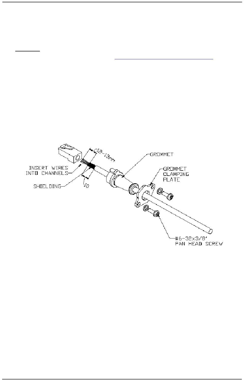
The Outdoor Unit side will be assembled according to the following steps (Figure 2-4):
• Insert seal bracket (grommet clamping plate) on the cable.
• Insert rubber seal (grommet) on the cable.
• Crimp the RJ-45 Plug.
Figure
2-4: Cable preparation for Outdoor Unit
• Insert the RJ-45 to the Outdoor Unit (Figure 2-5).
• Insert NC-6 screws with spring washer to the seal bracket.

WaveIP
Ltd.
WipAir 6000/3000 Installation Guide
Page
23
of 32
Figure
2-5: Cable assembly to Outdoor Unit
Figure
2-6: Cable insertion to Outdoor Unit.
• Fasten the seal bracket (Figure 2-7).
• The unused port should be left sealed.
Figure
2-7: Cable connection to Outdoor Unit
WaveIP
Ltd.
WipAir 6000/3000 Installation Guide
Page
24
of 32
2
2.
.3
3.
.7
7
I
In
nd
do
oo
or
r
O
Ou
ut
tl
le
et
t
I
In
ns
st
ta
al
ll
la
at
ti
io
on
n
The Indoor Outlet is wall mounted.
The Indoor Outlet side cables assembled as follows:
1. Crimp the RJ-45 Plugs on cable ends to form the Outdoor Unit cable.
2. Plug the Outdoor Unit cable to the RJ-45 Jack marked “OUTDOOR”.
3. Plug standard CAT5 cable from the PC to the RJ-45 Jack marked “10/100 B-T”.
4. Plug the DC plug from the AC/DC power supply to the DC jack marked
“48VDC”.
Note: Do not attach standard CAT5 cable from the PC to the Indoor Unit RJ-
45 jack marked “OUTDOOR”. Connecting the PC directly to the Outdoor
Unit may cause damaged to the Ethernet NIC in the PC.
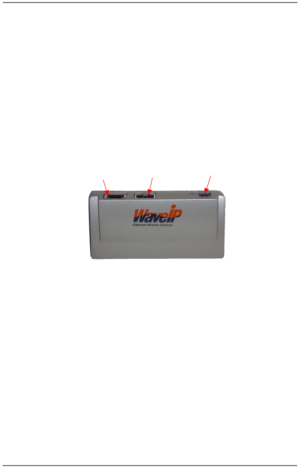
To Outdoor Unit (MU/SU) To Ethernet To Power Supply
Figure
2-8: Indoor Outlet
The indoor outlet provides the air and Ethernet link status via LEDs:
1. Air link (green LED) – indicates air connectivity of the SU to the MU.
2. Ethernet link (orange LED) – indicates Ethernet connectivity to the unit.
WaveIP
Ltd.
WipAir 6000/3000 Installation Guide
Page
25
of 32
2
2.
.3
3.
.8
8
G
Gr
ro
ou
un
nd
di
in
ng
g
2
2.
.3
3.
.8
8.
.1
1
G
Gr
ro
ou
un
nd
di
in
ng
g
t
th
he
e
O
Ou
ut
td
do
oo
or
r
U
Un
ni
it
t
(
(M
MU
U
/
/S
SU
U)
)
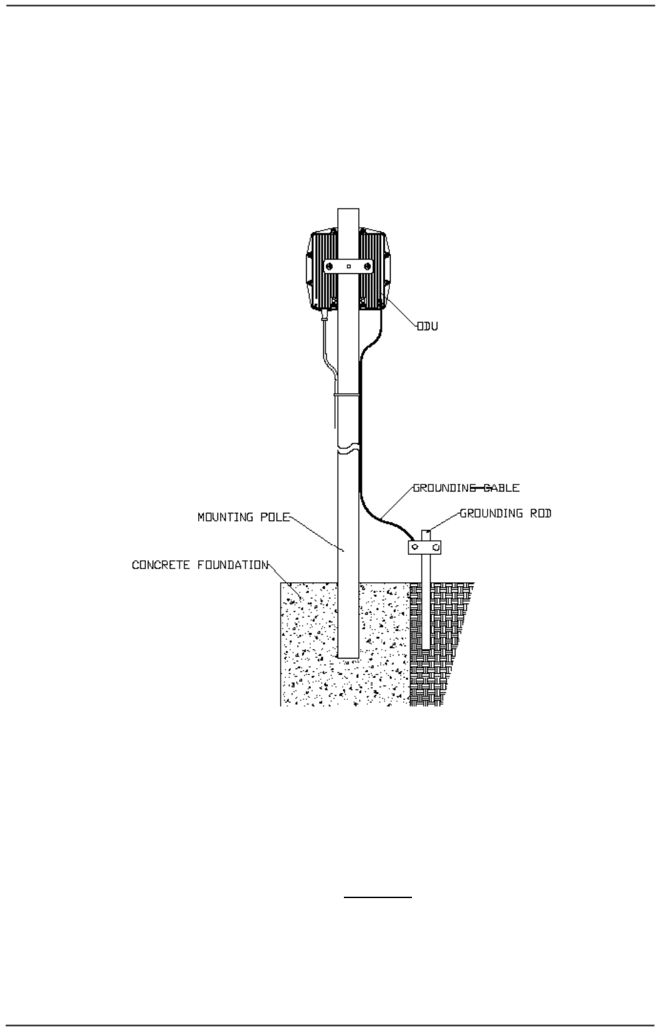
The outdoor unit shall be connected to a protective earth with not less than 10 AWG
conductors having green-yellow insulation. The following figure shows the grounding
cable from outdoor unit external screw to adjacent grounding rod. The cable should
be long enough to reach from the mounting pole to the grounding rod with 3 to 6 feet
extra to allow for strain relief.
Figure
2-9: Ground Connection to Outdoor Unit
Protection from Lightning
US National Electric Department of Energy Handbook 1996 specifies that radio and
television lead-in cables must have adequate surge protection at or near the point of
entry to the building. The code specifies that any shielded cable from a detached
antenna must have the shield directly connected to a 10 AWG wire that connects to
the building ground electrode.
The ground wire shall be terminated with UL listed lug with a diameter of 0.2 inch
(5.2 mm).
The ground lug will need to be suitable for terminating on aluminum materials, such
as the use of an aluminum connector and aluminum ground conductor.
WaveIP
Ltd.
WipAir 6000/3000 Installation Guide
Page
26
of 32
FCC Notice
This equipment has been tested and found to comply with the limits for Class B digital
device, pursuant to part 15 of the FCC Rules. These limits are designed to provide
reasonable protection against harmful interference in a residential installation. This
equipment generates, uses and can radiate radio frequency energy and, if not
installed and used in accordance with the instructions, may cause harmful
interference to radio communications. However, there is no guarantee that
interference will not occur in particular installation. If this equipment does cause
harmful interference to radio or television reception, which can be determined by
turning the equipment off and on, the user is encouraged to try to correct the
interference by one or more of the following measures:
• Reorient the relocate-receiving antenna.
• Increase the separation between the equipment and receiver.
• Connect the equipment into an outlet on a circuit different from that to which
the receiver is connected.
• Consult the dealer or an experienced radio/TV technician for help.
This device must accept any interference received including interference that may
cause undesired operation. Any unauthorized modification or changes to this device
without the express approval of WaveIP may void the user’s authority to operate this
device. Furthermore, this device intended to be used only when installed in
accordance with the instructions outlined in this manual. Failure to comply with these
instructions may also void the user’s authority to operate this device and/or the
manufacturer’s warranty
2
2.
.4
4
C
Co
on
ns
se
ec
cu
ut
ti
iv
ve
e
A
AP
P
C
Co
on
nn
ne
ec
ct
ti
io
on
n
Consecutive connection is done by plugging data crossover CAT5 cable between SU
and consecutive MU. This cable will also provide power redundancy to the units.
Total length of all wires should not exceed 300 feet each (91 meters).
Figure
2-10: Consecutive link principle
WipAir MU
WipAir SU
WipAir M
U
WipAir SU

WaveIP
Ltd.
WipAir 6000/3000 Installation Guide
Page
27
of 32
2
2.
.5
5
S
Sy
yn
nc
ch
hr
ro
on
ni
iz
za
at
ti
io
on
n
WipAir 6000/3000 was designed to work with co-located antennas. That means that
two or more units can be mounted close to each other.
Time synchronization allows reusing frequencies between co-located links and
configured with the Link Manager advanced window.
The synchronization signal is generated by an external GPS (1 PPS).
To configure time synchronization, set all MUs to synchronization Enable and Slave
mode.
Please refer to WipAir_6000_3000_configuration_manual.pdf for more information.
Note: The distance between any two antennas should be at least 50 cm.

WaveIP
Ltd.
WipAir 6000/3000 Installation Guide
Page
28
of 32
3
3.
.
W
Wi
ip
pA
Ai
ir
r
6
60
00
00
0
T
Te
ec
ch
hn
ni
ic
ca
al
l
S
Sp
pe
ec
ci
if
fi
ic
ca
at
ti
io
on
ns
s
3
3.
.1
1
R
Ra
ad
di
io
o
3
3.
.2
2
N
Ne
et
tw
wo
or
rk
ki
in
ng
g
a
an
nd
d
M
Ma
an
na
ag
ge
em
me
en
nt
t
3
3.
.3
3
P
Ph
hy
ys
si
ic
ca
al
l
a
an
nd
d
E
En
nv
vi
ir
ro
on
nm
me
en
nt
ta
al
l
-67
-70
-72
-78
-80
-83
-85
-87
Sensitivity @ 20 MHz (dBm)
300 270 240 180 120 90 60 30 Data Rate @ 40 MHz (Mbps)
50,000 Packets Per Second PPS
AIS – Automatic Interference Sensibility
ACM – Adaptive Coding & Modulation
ACS – Automatic Channel Selection
FEC – Forward Error Correction, k = 1/2, 2/3, 3/4, 5/6
Fast ARQ
–
Automatic Retransmit reQuest
Handling Interference
Up to 130 Km Range
Up to 200 Mbps (100 Mbps Full Duplex) Net Throughput
65 58.5 52 39 26 19.5 13 6.5 Data Rate @ 10 MHz (Mbps)
32.5 29.25 26 19.5 13 9.75 6.5 3.25 Data Rate @ 5 MHz (Mbps)
130
117
104
78
52
39
26
13
Data Rate @ 20 MHz (Mbps)
5/6 3/4 2/3 3/4 1/2 3/4 1/2 1/2 FEC
64QAM 16QAM QPSK BPSK Modulation
128-bit AES & MAC level authentication Encryption & Security
Configurable up to 26 dBm, 40 dB dynamic range Output Power
Advanced OFDM 2x2 dual polarization MIMOWaveform
Configurable – 5 / 10 / 20 / 40 MHz Channel Size
700–900 MHz, 2.3-2.5 GHz, 3.3-3.8 GHz, 4.9 GHz, 5.x GHz Radio Frequency
Point
-
to
-
Point (PTP), Point
-
to
-
Multipoint (PTMP)
Topology
Transparent or tagging/stripping
VLAN
Based on 802.1q & 802.1p
QoS
WEB, EMS, SNMP, Telnet, Built in throughput tests and RF Analyzer tools
Management
Time Division Duplex (TDD)
–
Dynamic or Symmetric
Access Technology
1ms typical
Data Latency
Layer 2 transparent bridging
Traffic Handling
19 x 19 x 4 cm (external antenna port) Mechanical
95% non condensing (Rainproof) Operating Humidity
Power over Ethernet (PoE) - 48 VDC Power
100-240 VAC, 47-63 Hz
10 x 5 x 2.5 cm
PoE Adapter:
• Input Power
•
Mechanical
Wall or pole Mounting
-30
o
c to 55
o
c Operating Temperature
< 6Watt Power Consumption
RJ – 45 Connector Type
2 X 10/100 Base-T (ODU) Physical Interface

WaveIP
Ltd.
WipAir 6000/3000 Installation Guide
Page
29
of 32
4
4.
.
W
Wi
ip
pA
Ai
ir
r
3
30
00
00
0
T
Te
ec
ch
hn
ni
ic
ca
al
l
S
Sp
pe
ec
ci
if
fi
ic
ca
at
ti
io
on
ns
s
4
4.
.1
1
R
Ra
ad
di
io
o
4
4.
.2
2
N
Ne
et
tw
wo
or
rk
ki
in
ng
g
a
an
nd
d
M
Ma
an
na
ag
ge
em
me
en
nt
t
4
4.
.3
3
P
Ph
hy
ys
si
ic
ca
al
l
a
an
nd
d
E
En
nv
vi
ir
ro
on
nm
me
en
nt
ta
al
l
128-bit AES & MAC level authentication Encryption & Security
150 135 120 90 60 45 30 15 Data Rate @ 40 MHz (Mbps)
-67 -70 -72 -78 -80 -83 -85 -87 Sensitivity @ 20 MHz (dBm)
Up to 120 Mbps (60 Mbps Full Duplex) Net Throughput
50,000 Packets Per Second PPS
AIS – Automatic Interference Sensibility
ACM – Adaptive Coding & Modulation
ACS – Automatic Channel Selection
FEC – Forward Error Correction, k = 1/2, 2/3, 3/4, 5/6
Fast ARQ
–
Automatic Retransmit reQuest
Handling Interference
Up to 130 Km
Up to 80 Km with integrated antennas
Range
32.5 29.25 26 19.5 13 9.75 6.5 3.25 Data Rate @ 10 MHz (Mbps)
16.25
14.625
13 9.75 6.5 4.875 3.25 1.625 Data Rate @ 5 MHz (Mbps)
65 58.5 52 39 26 19.5 13 6.5 Data Rate @ 20 MHz (Mbps)
5/6 3/4 2/3 3/4 1/2 3/4 1/2 1/2 FEC
64QAM 16QAM QPSK BPSK Modulation
Configurable up to 26 dBm, 40 dB dynamic range Output Power
Advanced OFDM Waveform
Configurable – 5 / 10 / 20 / 40 MHz Channel Size
700–900 MHz, 2.3-2.5 GHz, 3.3-3.8 GHz, 4.9 GHz, 5.x GHz Radio Frequency
Point
-
to
-
Point (PTP), Point
-
to
-
Multipoint (PTMP)
Topology
Transparent or tagging/stripping
VLAN
Based on 802.1q & 802.1p
QoS
WEB, EMS, SNMP, Telnet, Built in throughput tests and RF Analyzer tools
Management
Time Division Duplex (TDD)
–
Dynamic or Symmetric
Acces
s Technology
1ms typical
Data Latency
Layer 2 transparent bridging
Traffic Handling
19 x 19 x 4 cm (external antenna port) Mechanical
95% non condensing (Rainproof) Operating Humidity
Power over Ethernet (PoE) - 48 VDC Power
100-240 VAC, 47-63 Hz
10 x 5 x 2.5 cm
PoE Adapter:
• Input Power
•
Mechanical
Wall or pole Mounting
-30
o
c to 55
o
c Operating Temperature
< 6Watt Power Consumption
RJ – 45 Connector Type
2 X 10/100 Base-T (ODU) Physical Interface

WaveIP
Ltd.
WipAir 6000/3000 Installation Guide
Page
30
of 32
5
5.
.
A
Ap
pp
pe
en
nd
di
ix
x
A
A
–
–
O
Ou
ut
td
do
oo
or
r
C
Ca
ab
bl
le
es
s
S
Sc
ch
he
em
me
e
5
OR/W
7
6 7
GR
5
BR
5
BR/W
7
GR
RJ-RJ-DATA+POWER+LEDS-CROSS
BL/W
3
81
BR/W
RJ-RJ-DATA+POWER+LEDS-STRAIGHT
8
GR/W
3
BL
4
OR/W
8
7
GR/W
OR/W
BL
OR
1
INDOOR TO OUTDOOR
BL/W
1
GR/W
4
2
BR
3
BL/W
4
BR
3 2
GR OR/W
2
BR/W BR
6
BL
GR
6
OR
BR/W
6 4
OR
5
BL
GR/W
SU TO CONSECUTIVE AU
1
OR
BL/W
28
Figure
5-1: Outdoor Cables Scheme
Note: In order to comply with CAT5 91 meters cable
Pins 1,2 must be on a twisted pair wire!
Pins 3,6 must be on a twisted pair wire!

WaveIP
Ltd.
WipAir 6000/3000 Installation Guide
Page
31
of 32
6
6.
.
A
Ap
pp
pe
en
nd
di
ix
x
B
B
–
–
R
RF
F
C
Ch
ha
an
nn
ne
el
l
L
Li
is
st
ts
s
6
6.
.1
1
F
FC
CC
C
o
op
pe
er
ra
at
ti
in
ng
g
B
Ba
an
nd
d:
:
5
57
72
25
5
M
MH
Hz
z
-
-
5
58
85
50
0
M
MH
Hz
z.
.
Channel
No.
5 MHz Channel
Frequency
[MHz]
10 MHz Channel
Frequency
[MHz]
20 MHz Channel
Frequency
[MHz]
40 MHz Channel
Frequency
[MHz]
1 5730
2 5735 5735 5735
3 5740 5740 5740
4 5745 5745 5745 5745
5 5750 5750 5750 5750
6 5755 5755 5755 5755
7 5760 5760 5760 5760
8 5765 5765 5765 5765
9 5770 5770 5770 5770
10 5775 5775 5775 5775
11 5780 5780 5780 5780
12 5785 5785 5785 5785
13 5790 5790 5790 5790
14 5795 5795 5795 5795
15 5800 5800 5800 5800
16 5805 5805 5805 5805
17 5810 5810 5810 5810
18 5815 5815 5815 5815
19 5820 5820 5820 5820
20 5825 5825 5825 5825
21 5830 5830 5830 5830
22 5835 5835 5835
23 5840 5840 5840
24 5845
Figure
6-1: RF channel List

WaveIP
Ltd.
WipAir 6000/3000 Installation Guide
Page
32
of 32
7
7.
.
A
Ap
pp
pe
en
nd
di
ix
x
C
C
–
–
F
FC
CC
C
A
Ap
pp
pr
ro
ov
ve
ed
d
A
An
nt
te
en
nn
na
as
s
Antenna
Type
Model Gain
[dBi]
Beam
Width
Dimension
[mm]
Flat panel SPDB-5159-23V12D 23 10º x 10º 305x305x15
MT-485025/NVH 23 10º x 10º 371x371x40
MT-485025/CVH 23 10º x 10º 371x371x40
Dish DP-5X-285D-005 28.5 5º x 5º 2ft
Figure
7-1: Integrated / external antennas for WipAir 6000/3000