Wavetronix SS225 SmartSensor Matrix™ User Manual
Wavetronix, LLC SmartSensor Matrix™
User Manual

1
2
© 2008 Wavetronix LLC. All Rights Reserved.
The Company shall not be liable for any errors contained herein or for any damages arising
out of or related to this document or the information contained therein, even if the Company
has been advised of the possibility of such damages. This document is intended for
informational and instructional purposes only. The Company reserves the right to make
changes in the specifications and other information contained in this document without
prior notification.
FCC Part 15 Compliance: This device complies with Part 15 of the Federal Communications
Commission (FCC) rules which states that operation is subject to the following two
conditions: (1) this device may not cause harmful interference, and (2) this device must
accept any interference received, including interference that may cause undesirable
operation. FCC compliance statements for applicable optional modules are to be found in
the module specifications. Unauthorized changes or modifications not expressly approved by
the party responsible for compliance with the FCC rules could void the user’s authority to
operate this equipment.
Disclaimer: The advertised detection accuracy of the company’s sensors is based on both
external and internal testing, as outlined in each product’s specification document. Although
our sensors are very accurate by industry standards, like all other sensor manufacturers we
cannot guarantee perfection or assure that no errors will ever occur in any particular
applications of our technology. Therefore, beyond the express Limited Warranty that
accompanies each sensor sold by the company, we offer no additional representations,
warranties, guarantees or remedies to our customers. It is recommended that purchasers
and integrators evaluate the accuracy of each sensor to determine the acceptable margin of
error for each application within their particular system(s).
3
Introduction ............................................................................................................................. 5
SmartSensor Matrix Package .......................................................................................... 6
Selecting a Mounting Location ........................................................................................ 8
Installing the SmartSensor Matrix .................................................................................... 12
Selecting a Mounting Height ......................................................................................... 12
Attaching the Mount Bracket to the Pole .................................................................... 13
Attaching the Sensor to the Mount Bracket ............................................................... 14
Aligning the Sensor to the Roadway ............................................................................ 15
Applying Silicon Dielectric Compound ......................................................................... 17
Connecting the SmartSensor Cable ............................................................................. 17
Connecting Power, Surge, and Communications ........................................................... 21
Mounting the Back Plate ............................................................................................... 22
Connecting AC Power ..................................................................................................... 22
Controlling DC Power Distribution ................................................................................ 25
Providing System Surge Protection .............................................................................. 27
Terminating the Sensor Cables ..................................................................................... 29
Configure Contact Closure Communications .................................................................. 33
Installing SmartSensor Manager Matrix Configuration Tool ........................................ 43
Wavetronix Configuration Toolkit ................................................................................. 43
Installing SSMMX ............................................................................................................ 45
Microsoft .NET Framework............................................................................................. 49
Communication ................................................................................................................... 51
Serial Connection ............................................................................................................ 52
Internet Connection ........................................................................................................ 54
Virtual Connection ........................................................................................................... 56
Virtual Sensor File ........................................................................................................... 57
Address Book ................................................................................................................... 58
Viewing Connection Info ................................................................................................. 59
Communication Error Log .............................................................................................. 60
Uploading the Sensor’s Embedded Software ............................................................. 60
Sensor Settings .................................................................................................................... 63
Sensor Setup ........................................................................................................................ 65
Lanes and Stop Bars ....................................................................................................... 65
Move Sensor..................................................................................................................... 67
Restart Automatic Lane Configuration ........................................................................ 68
4
Capture Lanes and Stop Bars to Edit Area .................................................................. 68
Make Manual Adjustments ........................................................................................... 68
Save Desired Changes to the Sensor ........................................................................... 72
Zones and Channels ....................................................................................................... 72
Verification ....................................................................................................................... 75
Tools ...................................................................................................................................... 77
Backup / Restore ............................................................................................................ 77
Rack Cards Tools ............................................................................................................. 79
Tracker Logging ............................................................................................................... 81
Appendix ............................................................................................................................... 84
Appendix A – SmartSensor Matrix (SS225) Specifications ...................................... 84
Appendix B – Matrix Cable Connector Assembly Information ................................. 84
Appendix C – SmartSensor Matrix Cable Lengths ..................................................... 86
Appendix D – Click! 112/114 User Reference Guide ............................................... 87
Appendix E – Click! 221 User Reference Guide ......................................................... 94
5
Introduction
In the Introduction
SmartSensor Matrix Package
Selecting a Mounting Location
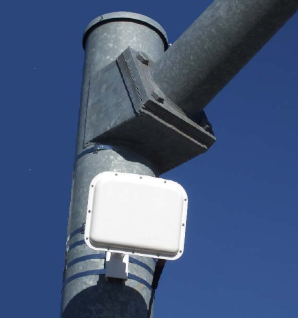
The Wavetronix SmartSensor Matrix™ traffic sensor is a stop bar presence detector
designed for use at signalized intersections (see Figure I-1). The SmartSensor
Matrix detects vehicle demand through the use of a 24.125 GHz (K band) operating
radio frequency. Classified as a Frequency Modulated Continuous Wave (FMCW)
radar, the SmartSensor Matrix detects and reports vehicle presence in as many as
10 lanes simultaneously.
Figure I-1: Wavetronix SmartSensor Matrix
SmartSensor Matrix is a first-of-its-kind radar vision device that delivers the
reliability of radar and the simplicity of non-intrusive detection for stop bar
applications. The unit will work consistently in all weather and lighting conditions to
keep your intersection running safely and efficiently. In most situations the sensor
is installed on the roadside in order to prevent the need for lane closures and traffic
control. Once the unit is installed, the configuration process is quick and easy.
After installation, this unit will require little or no on-site maintenance and can be
remotely configured. This user guide outlines the step-by-step process of installing
and configuring the SmartSensor Matrix. Any questions about the information in
this guide should be directed to Wavetronix or your distributor.
6
SmartSensor Matrix Package
SmartSensor Matrix is the radar vehicle sensing device used in a Wavetronix Stop
Bar Detection System. The minimal stop bar detection system package contains
the following items:
SmartSensor Matrix SS225 detector(s) with installed sensor back-plate
Sensor Mounting Kit(s)
Sensor Cable(s) and connectors(s)
Pre-wired cabinet unit (PCU) with installed underground surge, termination
blocks, and DC surge option
Detector Rack Card(s) with patch cable(s)
SmartSensor Manager Matrix (SSMMTX) software
SmartSensor Matrix User Guide
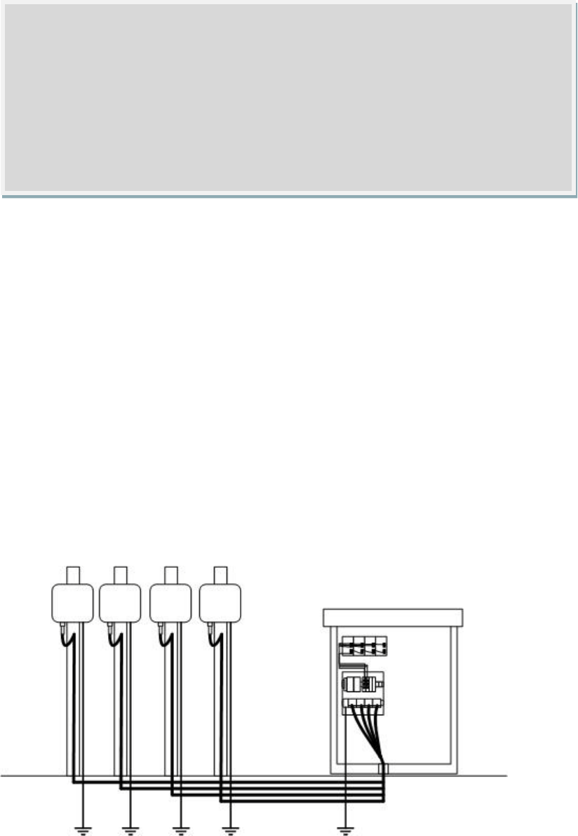
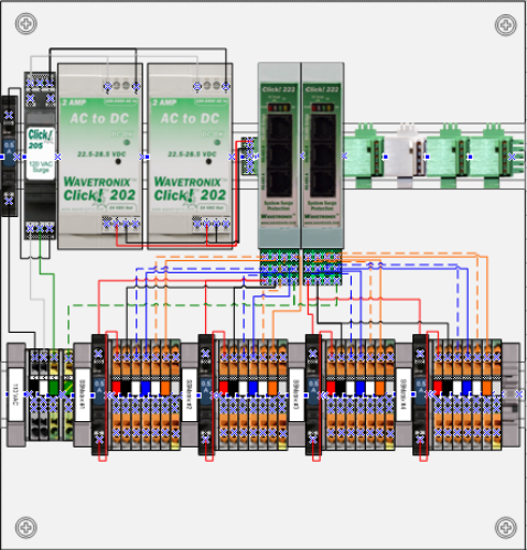
Standard packages are built and ready to order for 1, 2, 3 and 4 approach systems
with as many as eight sensors. Figure I-2 illustrates a 4-sensor system. Check the
packing slip for actual contents. If any of items are missing, note the serial
numbers located on the back of the sensors and contact your distributor.
Figure I-2: System Diagram of a 4-Sensor Wavetronix Stop Bar Detection System
Caution
Do not attempt to service or repair this unit. This unit does not contain any
components and/or parts serviceable in the field. Any attempt to open this unit,
except as expressly written and directed by Wavetronix, will void the customer
warranty. Wavetronix is not liable for any bodily harm or damage caused if service
is attempted or if the back cover of the SmartSensor unit is opened. Refer all
service questions to Wavetronix or an authorized distributor.
7
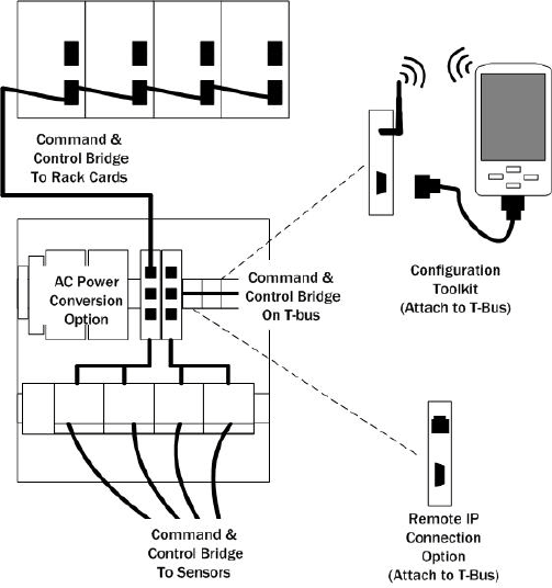
The total Wavetronix Stop Bar Detection system includes other recommended
options (see Figure I-3) which include:
• AC power conversion option – This option is pre-loaded onto the PCU and is
normally recommended by Wavetronix instead of the DC surge protection
option, because it will not burden the existing DC power modules in the
cabinet and it will provide reliable power for the sensors and PCU
components.
Wavetronix Configuration Toolkit – The toolkit makes installation and
maintenance more convenient than ever. The toolkit provides both wired
and wireless configuration capability using a handheld configuration utility
and a Click! 421. The Click! 421 connects to the Command and Control
Bridge via a T-bus expansion port. The handheld configuration tool comes
preloaded with SmartSensor Manager and Click! Supervisor software, for
simple management of your system.
Remote IP Connection option – This option is pre-loaded onto the PCU and
is recommended for remote management.
Figure I-3: Integration of Options via the Command and Control Bridge

8
The Wavetronix Stop Bar detection system is part of the broader Wavetronix
Intersection Detection System which includes certified systems for advance
(dilemma zone) and mid-block (system control) detection. The Wavetronix
Intersection Detection System has been designed to simply integrate the reliable
presence detection data of SmartSensor Matrix, with the superior passage detection
data of SmartSensor Advance, and high-quality count data of SmartSensor HD in
order to control signalized intersections more safely and efficiently than ever before.
Contact your authorized Wavetronix representative to learn how these packages can
be cost-effectively bundled together.
In addition the complete line of Click! products and Click! Cabinet Systems offers a
connectivity and integration solution for virtually every intersection application.
Contact Wavetronix technical services for assistance with your application specific
integration questions.
Selecting a Mounting Location
Consider the following guidelines when selecting a mounting location for each
SmartSensor Matrix unit:
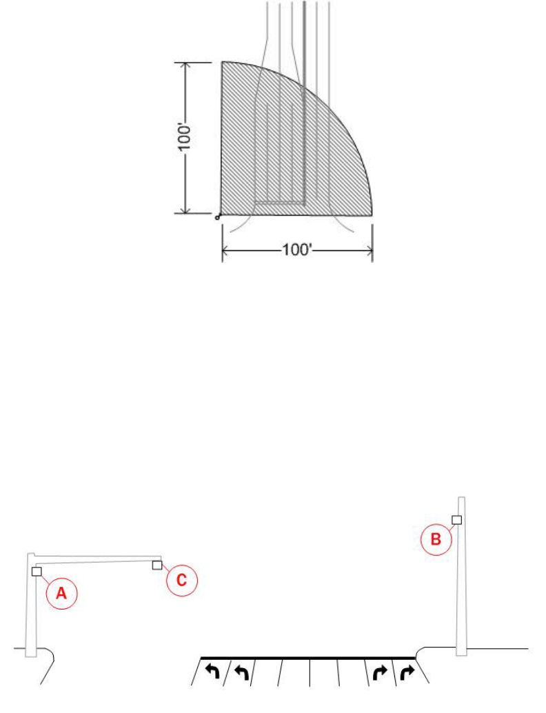
Corner radar – SmartSensor Matrix is a corner radar with a panoramic
90°degree 100-foot view. The corner radar vision device detects in traffic in
a two-dimensional matrix to provide industry leading stop bar detection
performance. The sensor’s mounting location should be selected so that all
stop bar detection zones on an approach are within 6 to 100-foot radial
distance. Figure I.4 presents a top down view of a corner radar mounted to
detect the stop bar on a four lane intersection approach. The corner radar
device uses its radar vision to automatically determine the location and
orientation of lanes and stop bars within its field-of-view. It then detects
vehicle presence on a lane-by-lane basis.
Note
The Wavetronix Intersection Detection System provides a Command and Control
Bridge for management of all connected SmartSensor and Click! devices. This
Command and Control Bridge is completely separate from the dedicated
channels used for communication of contact closure detection calls in real-time.
9
Figure I-4: Corner Radar
Mounting pole – The sensor is usually mounted on a corner vertical mast
pole or strain pole. On wide approaches the sensor can also be mounted on
the back side of a mast arm using an appropriate sensor mount. In either
case, the sensor should be mounted with at least a six-foot offset from the
first detected lane. Figure I.5 illustrates common mounting locations: A –
far side of approach, B- near side of approach, C – back side of mast arm.
Other mounting locations may be possible if these are not available at your
intersection. Contact Wavetronix Technical Services for assistance if you
would like to test an alternative mounting location.
Figure I-5: Mounting locations
Line-of-sight – Position the sensor so that it will have line-of-sight to the
entire detection area of interest. Avoid structural occlusion including trees,
signs, and other roadside structures.
Detection coverage – Position the sensor so that it will be able to reach all
the specified stop bar detection zones. Also consider that the sensor will
track vehicles as they enter and exit desired detection zones. Accordingly,
the sensor will often work better if you position detection coverage to track
vehicles for several feet before they reach the first zone in each lane.
10
Likewise, if the detection coverage is aligned so that the sensor has a view
several feet beyond the stop bar (downstream from the stop bar into the
intersection) it is more likely to have better performance of detecting queue
dissipation. With the installation software, the presence and location of the
stop bar in each lane can be configured in order to enable advanced logic to
minimize the effects of occlusion of small vehicles by queued traffic.
Closest roadside – It is recommended that you mount the sensor on the side
of the road closest to the lanes of primary interest. In many cases this will
be near side. However, if left turn detection is more critical than through
movement detection the closest road side may be the far side of the
approach. Always mount the sensor high enough to prevent traffic from
occluding approaching detections. If you mount the sensor on the back side
of a mast arm, mount the sensor near the end of the arm to reduce the
potential the mast arm or departing traffic to occlude approaching vehicles.
Mounting height - Mounting the sensor higher will generally improve line-of-
sight and decrease occlusion of vehicles. A minimum height of 15 feet is
recommended. If the sensor is mounted on a vertical pole with a mast arm,
it is recommended that the sensor be mounted to avoid occlusion of the
roadway by the mast arm. This may require mounting the sensor below the
mast arm.
Mounting offset – A minimum offset of 6 feet to the first lane of interest is
required.
Redundant detection – It is possible to have multiple sensors monitoring the
same approach.
Sensor proximity – When multiple sensors are mounted at the same
intersection, interference can be avoided by configuring each sensor to
operate on a unique RF channel. In cases, where zones are spread over
more than 100 feet, multiple sensors are needed.
Departing lanes – There is usually no need to view traffic in departing lanes
or to configure departing lanes. However, if they are configured then the
stop bar should NOT be configured.
Suspended electrical cables - The sensor is designed to work in the
presence of suspended power lines and other electrical cables, however
these cables should be mounted at least ten feet away from the front of the
sensor.
Neighboring structures and parallel walls – For best performance, it is
preferred that the sensor be mounted without signs or other flat surfaces
mounted directly behind it. This will help reduce multiple reflection paths
from a single vehicle.
Cable length – Ensure that you have sufficient homerun and sensor cabling.
Cable runs as long as 500 feet are achievable using 24 VDC operation and
the system’s native RS-485 communications. If you have an application
that requires a cable length longer than 500 feet, contact Wavetronix
technical services for assistance.
11
Part I
Installing SmartSensor Matrix
12
Installing the SmartSensor Matrix
In this Chapter
Selecting the Mounting Height
Attaching the Mount Bracket to the Pole
Attaching the Sensor to the Mount Bracket
Aligning the Sensor to the Roadway
Applying the Silicon Dielectric Compound
Connecting the SmartSensor Cable
Installing the SmartSensor Matrix is quick and easy. Once installed, SmartSensor
Matrix configures automatically and requires little or no on-site maintenance. The
installation process includes attaching the mounting bracket to the pole; attaching
the sensor to the mounting bracket; aligning the sensor; applying a silicon dielectric
compound to the sensor connector; and connecting the SmartSensor cable to the
sensor.
Selecting a Mounting Height
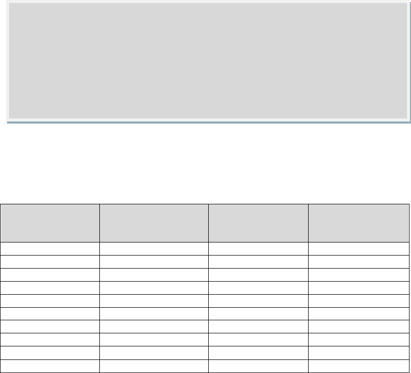
After selecting a mounting location within the recommended range of offsets (see
introduction), use Table 1.1 to select a mounting height.
Offset from first
Detecton Lane (ft)
Recommended
Mounting Height (ft)
Minimum
Mounting Height
(ft)
Maximum
Mounting Height
(ft)
6
17
15
30
10
18
15
30
15
19
15
30
20
20
15
30
25
21
15
30
30
22
15
30
35
23
15
30
40
24
15
30
45
25
15
30
50
26
15
30
Warning
Caution should be used when installing any sensor on or around active roadways.
Serious injury can result when installation is performed using methods that are
not in accordance with authorized local safety policy and procedures. Always
maintain an appropriate awareness of the traffic conditions and safety
procedures as they relate to specific locations and installations.

13
55
27
15
30
60 or more
28
15
30
Table 1.1
Attaching the Mount Bracket to the Pole
Before attaching the mount bracket to the pole, first make sure that your cables are
long enough to reach the sensor height and to stretch across the distance from the
sensor to the cabinet.
Follow the steps below to correctly attach the mount to the pole.
1. Insert the stainless steel straps through the slots in the mount bracket.
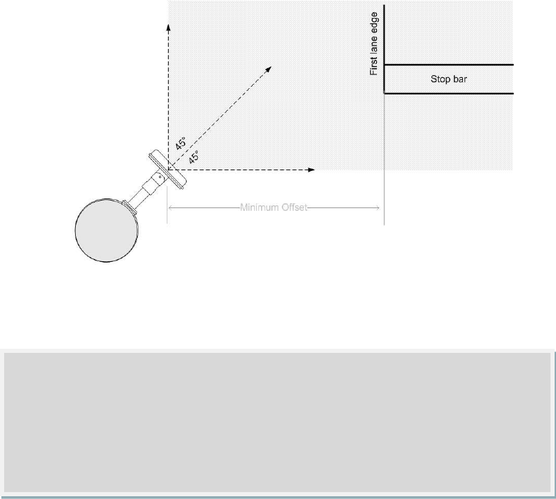
2. Position the mount on the pole so that the head of the mount is pointing
toward the lanes of interest at about a 45° angle. Figure 1.1 illustrates the
sensor mount pointed at a 45° angle. (Figure 1.1 also depicts the sensor
attached to the mount. This is intended to help visualize the objective of
pointing the mount at a 45°. The objective is that a 45°pointing will often
provide a ballpark alignment of the sensor beam over roadway, once the
sensor is attached. The next section of this chapter explains how to attach
the sensor.)
3. Tighten the strap screws.
Note
The sensor mount may need to be adjusted later to fine-tune the alignment.
This is most easily achieved using the double-swivel mount. One swivel joint is
used to pan the sensor beam left or right. The other swivel joint is used to tilt
the sensor down towards the roadway. If you are NOT using the double swivel-
mount be sure to keep the pole straps adjustable at this point in the
installation process.
Note
It is possible to mount the sensor lower than 15 feet in some scenarios. The
sensor will continue to detect vehicles at lower heights, but missed detections
due to occlusion may become more prevalent or problematic depending upon
your application.
14
Figure 1.1 – Attach the Mount Bracket to the Pole
Attaching the Sensor to the Mount Bracket
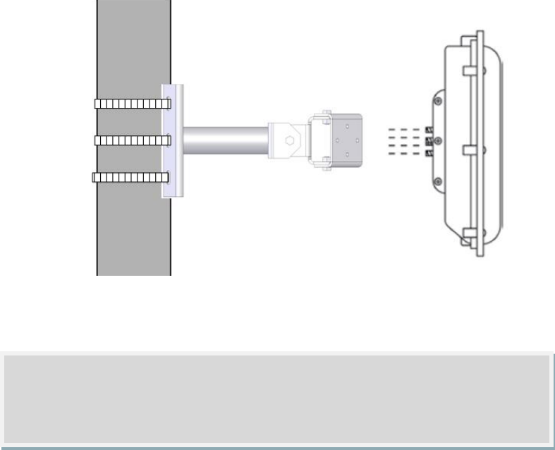
Use the following steps to securely fasten the sensor to the mount bracket:
1. Align the bolts on the sensor’s back plate with the holes in the mount
bracket. The 8-pin connector receptacle at the bottom of the unit should be
pointing towards the ground.
2. Place the lock washers onto the bolts after the bolts are in the mount
bracket holes.
3. Thread on the nuts and tighten (see Figure 1.2)
Note
If you are mounting the sensor to the back side of the mast arm, you will
probably need to mount the sensor down toward the road. This will allow you to
use one swivel to point down towards the road and the other to pan left and
right.
15
Figure 1.2 Attaching the Sensor to the Mount Bracket
Aligning the Sensor to the Roadway
In most applications, the goal is to position the corner radar so that its fan-shaped
footprint provides coverage of all lanes approaching the stop bar. The sensor’s view
fans out 45° to the left and 45° degrees to the right, creating a 90° corner radar.
To visualize the extent of the sensor beam an installer can use a square framing
tool (e.g. rafter square) or other solid surface with a right-angle. The tool can be
held above the sensor as a visual aid similar to the illustration in Figure 1.1. By
looking down both edges of the square instrument you can visualize the extent of
the radar’s coverage.
Note
Do NOT over-tighten the fasteners.
16
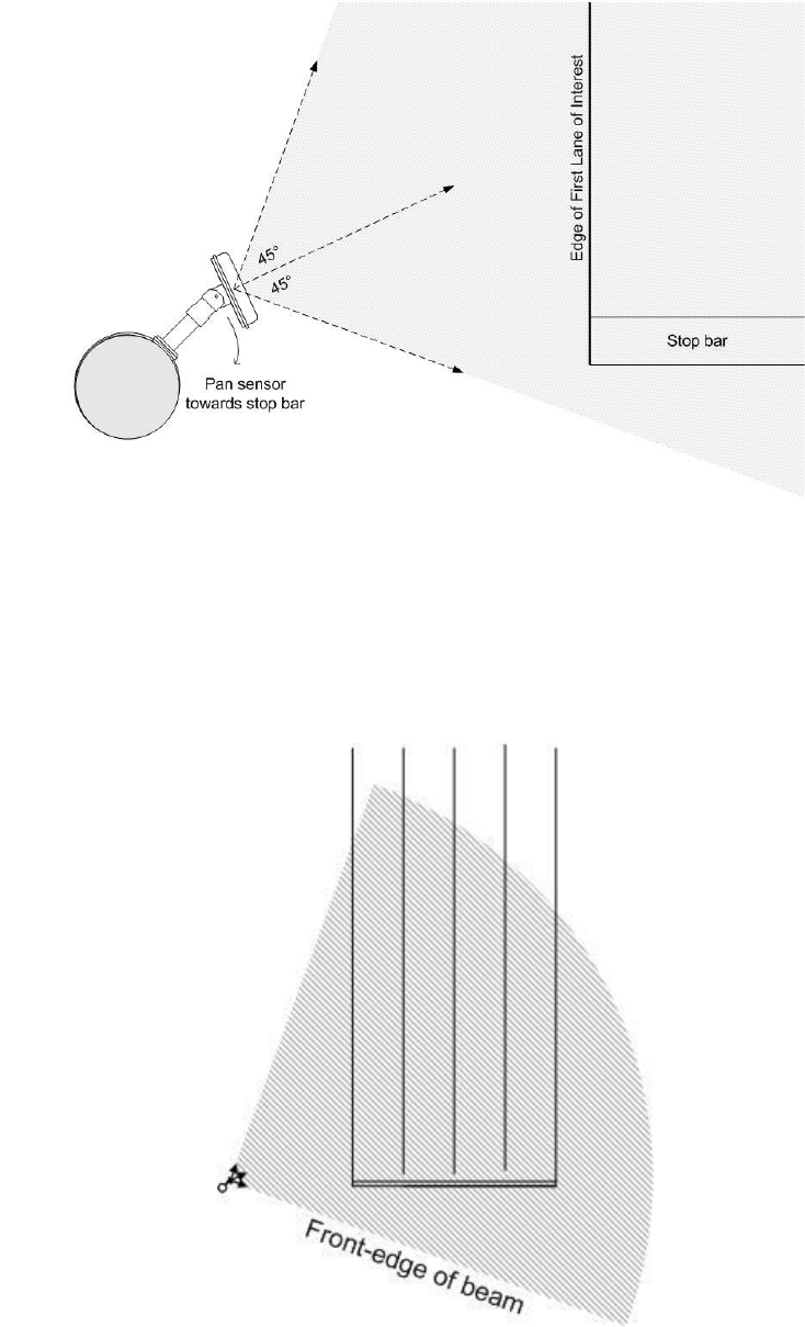
Figure 1.3 – Corner radar beam position
Usually the front-edge of the sensor’s beam is aligned to provide coverage beyond
the stop bar. This will allow placement of detection zones in beyond the stop bar
(not all vehicles stop behind the line), and it will also provide the sensor with a view
of vehicles exiting queues. If the sensor pole is upstream of the stop bar as in
Figure 1.2, it is recommended to pan in the direction of the stop bar.
Figure 1.4 – Sensor Aligned by Rotating Towards the Stop Bar

17
Use the following steps to correctly align SmartSensor Matrix.
1. Adjust the side-to-side angle so that the front-edge of the beam provides a
view downstream of the stop bar.
2. Tilt the sensor down so it is aimed at the center of the lanes of interest.
3. If necessary rotate the sensor back plate so that the bottom-edge of the
sensor is parallel with the roadway. This is necessary where the intersection
approach has a significant grade.
Applying Silicon Dielectric Compound
Use the following steps to correctly apply the silicon dielectric compound: Tear the
tab off of the tube of Silicon Dielectric Compound.
1. Squeeze about 25% of the silicon onto the pins of the receptacle-side of the
connector at the base of the SmartSensor Matrix (see Figure 1.5).
2. Be sure to wipe off any excess compound.
Figure 1.5 – Connector Receptacle (left) and Protective Earth Lug (right)
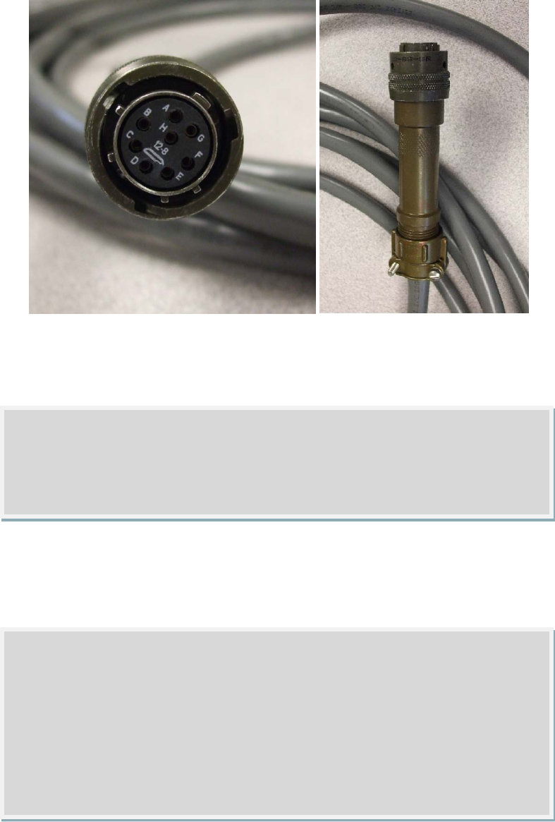
Connecting the SmartSensor Cable
The sensor connector is keyed to ensure proper connection (see Figure 1.6); simply
twist the plug end of the connector clockwise until you hear it click into place.
Use the following steps to connect the SmartSensor Matrix Cable:
1. Insert and turn the connector to attach it. Match up the key for a quick
connection.
2. Connect one end of a protective earth ground wire to the ground lug
terminal. A 12 AWG stranded wire is recommended for ground connections.
3. Connect the other end of a protective earth ground wire to an earth ground
connection point.
To avoid undue movement from the wind, strap the cable to the pole or run it
through a conduit, but leave a small amount of slack at the top of the cable to
reduce cable strain.
18
Figure 1.6 – Sensor Connector
(Left – Plug end with sockets A-H, Right – Plug and Back shell)
Route the SmartSensor Matrix home run cable from the sensor location back to the
main traffic cabinet. Then attach the cable to the sensor. Do not strip the service
end of the cable until after it has been routed through conduit. The cable should be
one continuous run without any splices.
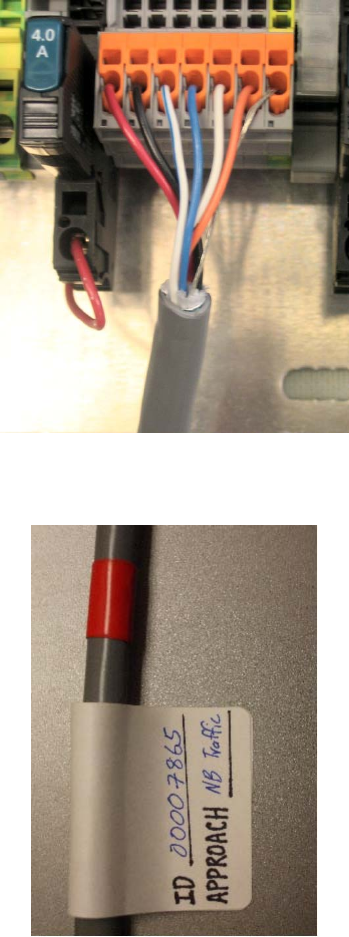
Once the sensor cable is routed into the cabinet, prepare to label the service end of
the cable. Before you label the sensor, you may want to carefully strip back the
cable jacket and insulation of the service end of the cable (see Figure 1.7). The
wires comprise: one DC power wire pair, two RS-485 communication pairs, and a
Note
The SmartSensor Matrix cable with connector can be purchased in standard
lengths (e.g. 50, 150, or 250 feet). If you need longer cable or would like to
create custom length cables, you can also purchase bulk spools of 1000-foot
cable. When using bulk spools, you will need to purchase the plug end of the
connector and the appropriate crimping tool separately. See Appendix D for
information on crimping.
Note
If you run the cable through the pole, do not drill through the sensor mount, as
the sensor and sensor mount may need to be adjusted in the future.
19
drain wire. The service end of the cable connects to plug-in terminals on the main
cabinet back plate.
Figure 1.7 – Service End Terminated At Traffic Cabinet Back Panel
Figure 1.8 – Service End Labeling
In Chapter 2 there is a section detailing how to properly terminate the service end of
the cable (see Figure 2.6). After landing each sensor cable, and powering each
sensor, you can enter location information specific to each sensor as described in
Chapter 4 (see Figure 4.2).

20
Note
To setup the network in an orderly fashion, it is recommended that labeling be
used on the service end of each SmartSensor Matrix cable. Label the cables
according to agency guidelines. In addition you may elect to use labels to
mark the last seven digits of the serial number on each sensor, and the
direction of traffic monitored (see Figure 1.8). This can help expedite software
naming of sensor description, location, and approach fields.
21
Connecting Power, Surge, and Communications
In this Chapter
Mounting the Pre-wired Cabinet Unit
Connecting AC Power
Controlling DC Power Distribution
Providing System Surge Protection
Terminating the Sensor Cables
Attaching the Serial Configuration Toolkit
Wiring Contact Closure Communications
After installation, each SmartSensor Matrix unit will need to be integrated into the
traffic cabinet for power, surge, and communications. Pre- wired cabinet units
(PCUs) are available for sensor integration. As an example, this chapter will detail
integration of a Wavetronix stop bar detection system PCU panel that
accommodates four SmartSensor Matrix units (one for each stop bar of a common
four approach intersection).
Figure 2.1 – Four approach Pre-built Cabinet Unit for SmartSensor Matrix
The standard four-approach PCU back plate is sized 11 inches wide and 11.5 inches
high. Softcopy and hardcopy plans of the cabinet unit wiring are available for
maintenance personnel. All wiring in the on the PCU is done using stranded wires
with wire ferrules for screw terminal connections. The stranded wires are flexible
22
and simplify maintenance. The wire ferrules provide a solid connection end point
for screw terminal connections.
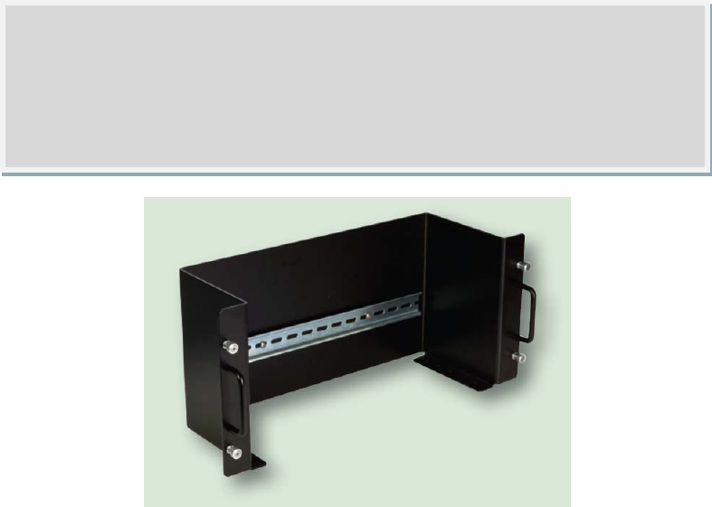
Mounting the Back Plate
Use the following steps to mount the back plate in the traffic cabinet:
1. Locate the space planned for mounting the back plate. Often, the PCU will
be able to mount on the side panel of a NEMA style cabinet.
2. Attach the back plate with the u-channel mounting screws.
Connecting AC Power
Since SmartSensor Matrix operates on 10-28 VDC, the standard Wavetronix stop
bar detection system back plates provide an AC power conversion option. If you
select this option, the back plate will be loaded with the necessary AC to DC power
conversion, power surge, and circuit breaker.
If you choose to have your PCU built without the AC power conversion sub-assembly,
you will need to tap into surplus DC power capacity resident in the traffic cabinet. In
this case, Wavetronix recommends the use of the Click! 221 to protect the PCU and
SmartSensor Matrix units from DC surges. The Click! 221 is an 8-amp DC surge
module. For wiring and other information on the Click! 221 see Appendix E.
Note
If you have a 330 series (170/2070 style cabinet) with a 19” EIA rack, please
contact Wavetronix Technical Services for assistance. Wavetronix can provide
modified PCUs that attach to a 19 inch rack.

23
The AC termination points for line (AC+, hot), neutral (AC-), and ground are found on
the bottom din rail next to the 110 VAC label. Use the following steps to connect
power wires from the AC terminal block or cord to the pluggable terminal blocks on
the bottom din-rail (see Figure 2.2):
1. Connect a neutral wire to the bottom-side of the white block labeled “N” for
neutral. The neutral wire is usually white.
2. Connect a ground wire to the bottom-side of the green block labeled “G” for
ground. The ground wire is usually green. (Please note that the ground
connection is different than the protective earth connection. See the section
on Providing System Surge Protection for instructions on connecting to
protective earth.)
3. Connect a line wire to the bottom-side of the black block labeled “L” for line.
The line wire is usually black.
4. Connect or turn on AC mains power.
5. Press the circuit breaker switch on the left side of the top din-rail to switch
power to the Wavetronix stop bar detection system panel. The switch is on
if the push button is below the level of the device housing. The switch is off
if the button is raised above the surface of the housing.
6. Verify that DC power is properly regulated by checking the Click! 201/202
devices to see that the DC OK LEDs are illuminated.
Caution
An authorized electrical technician should perform installation and operation
of this unit. Persons other than authorized and approved electrical technicians
should NOT attempt to connect this unit to a power supply and/or traffic
control cabinet, as there is a serious risk of electrical shock through unsafe
handling of the power source. Extreme caution should be used when
connecting this unit to an active power supply.
Warning
Make sure power to AC mains is disconnected while wiring the AC input.
24
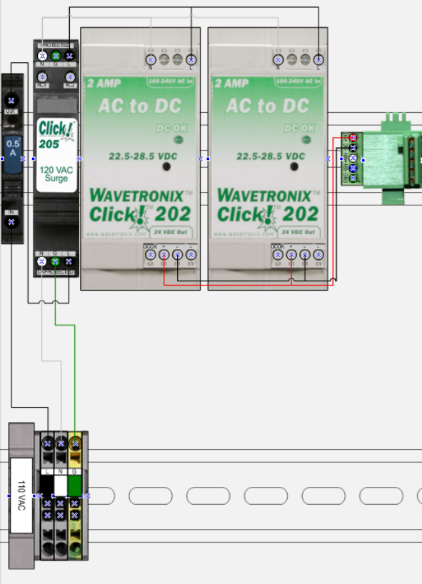
Figure 2.2: AC Power Conversion
Each AC power conversion sub-assembly will come pre-wired as shown in Figure 2.2.
The main three components of the sub-assembly include:
Click! 201/202 AC to DC converter
Click! 205 AC surge module
Click! 206 circuit breaker and switch
A Click! 201 provides 1 amp of power and is capable of powering a single sensor,
while a Click! 202 provides 2 amps and can power two sensors. The Click! 205
helps limit current surges on the power lines; the Click! 206 interrupts power during
overload conditions and provides a convenient way to turn power on and off for the
entire system.
A PCU will use wired blocks with one terminal at the top and two on the bottom
when one conductor needs to be routed two directions. For example, although not
shown in Figure 2.2, this type of wired block is used to connect AC power from the

25
one Click! 205 to both Click! 202 modules. These blocks are also used to route the
DC power from both Click! 202 to the 5-position screw terminal on the left side of
the T-bus.
Controlling DC Power Distribution
The 24V DC+ and DC- (common) connections from the AC to DC power convertors
distribute power to the sensors via the Click! 222 System Surge Protection units
(see Figure 2.2). The DC power wires out of the System Surge Protection units are
connected to a 2.0 Amp circuit breaker for each SmartSensor Matrix. The circuit
breakers provide a convenient way to switch power to each sensor independently.
When a switch is off power distribution is disabled.
To enable or disable DC power distribution, use the following steps:
1. Switch the main circuit breaker (left side of upper din-rail).
2. Switch the individual circuit breaker (left side of each sensor’s set of
terminal blocks.
Tip
With either the main or individual circuit breakers, you will enable power
distribution when the switch is on. When the switch button is level with the
device housing (pushed in) the switch is on. When the switch button is raised
above the surface of the housing (popped out) the switch is off. If you cannot
visually whether the button is pushed in or popped out, you should be able to
feel it with your hands.
26
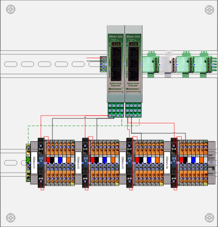
Figure 2.2 – DC Power Distribution from System Surge Protection
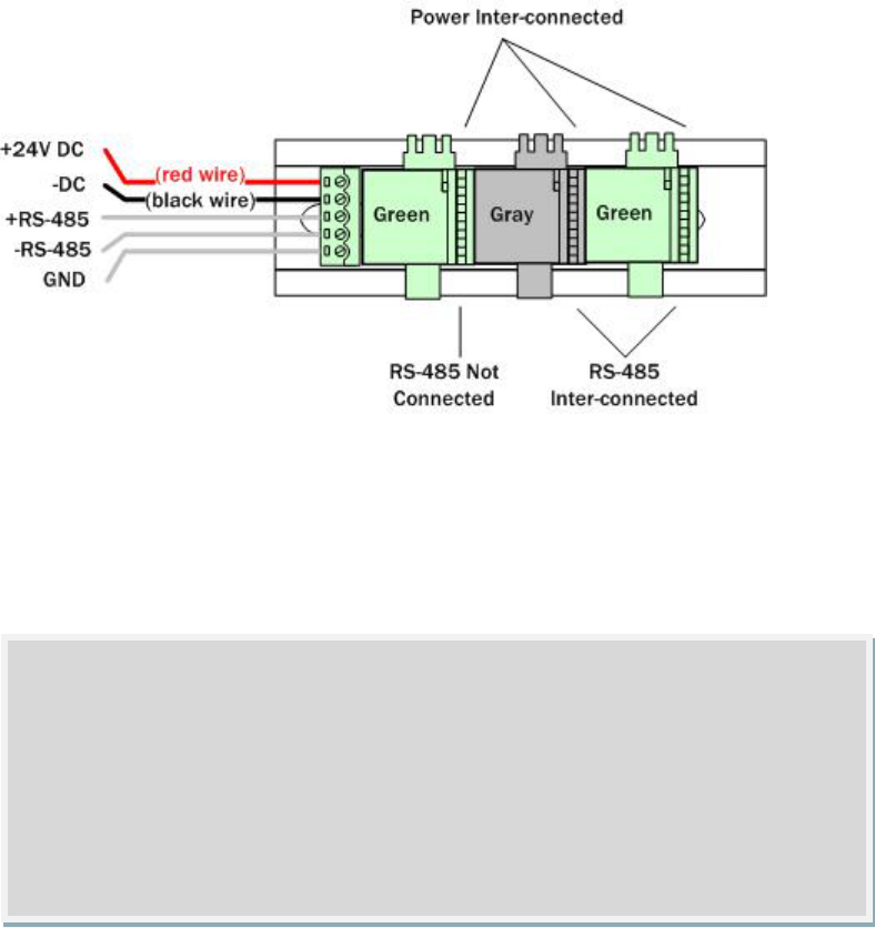
The four-approach PCU has the 24VDC power wired from the output of the AC to DC
convertor into a 5-position screw terminal on the left side of the T-bus. This T-bus
has both green and gray connectors. Green T-bus connectors conduct DC power and
RS-485 communications from the left to the right side of the modules. Gray T-bus
connectors conduct only DC power from the left to the right side of the modules.
This means that a device that is attached to a gray T-bus connector will send RS-
485 communications to devices on its right side, but not its left side (see Figure
2.3).
For example, the gray T-bus in Figure 2.2 has its communication lines connected
with the two green T-bus devices on the right side, but not to the one on the left
side.
27
Figure 2.3 – T-bus Pinout Diagram
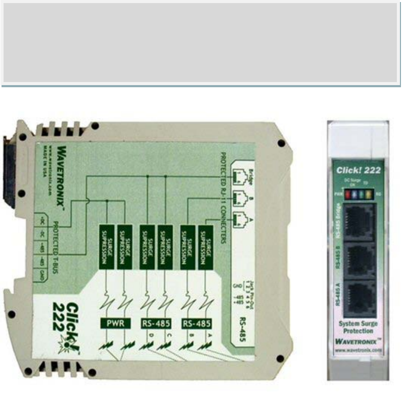
Providing System Surge Protection
The Wavetronix Click! 222 system surge protection devices are designed to prevent
electrical surges conducted along underground cables from damaging the cabinet
equipment.
The power and RS-485 serial connections on the T-BUS and faceplate are protected
from surges on the incoming wires of the sensor cable. The sensor cables are
connected via the terminal blocks on the PCU to the screw terminals on the bottom
side of the Click! 222. The screw terminals on the bottom side of the Click! 222
have circuitry that prevents impedance matching issues on long non-uniform cable
runs to the sensor installation sites.
The PWR and DC Surge OK LEDs indicate that the device is powered and that DC
surge protection is operational. The TD (transmit data) and RD (received data) LEDs
indicate when data is transmitted or received over the RS-485 T-bus, Bridge, C & D
ports. However, the TD and RD LEDs do not indicate data transmitted on RS485 A
or RS485 B. Furthermore, after an electrical surge there is no method to determine
if the RS-485 surge protection is still operational.
Note
The SmartSensor Matrix unit has built-in surge protection and there is not a
need to use a pole-mount box for surge protection. However, it is strongly
recommended that the sensor be connected to a surge protection device in the
main traffic cabinet. If you choose not to use surge protection in your main
traffic cabinet, please contact Wavetronix Technical Services for assistance.
28
Figure 2.4 – System Surge Protection
The communication wires running from the pluggable termination blocks on the
PCU’s bottom din-rail to the system surge protection devices are connected to
provide three independent serial connections:
1. Command and Control Bridge
2. Dedicated communications for sensor A detection calls
3. Dedicated communications for sensor B detection calls.
One serial connection is an RS-485 Bridge that enables a multi-drop shared
communication bus between all sensors on the panel. In a Wavetronix stop bar
detection system, the Bridge connection is designed for command and control of all
SmartSensor Matrix units, rack cards, and other connected Click! devices. This bus
is formed by wiring the C and D terminal blocks and landing the system surge
devices on a shared T-BUS.
Note
If the DC Surge OK LED is not lit up when the Click! 222 is powered, call
Wavetronix Technical Services for assistance.

29
The other two serial connections provide dedicated communications to each sensor.
During real-time traffic operations with multiple sensors, one sensor will send
detection calls to a detector rack card over port A, and the other will send detection
calls to another detector rack card over port B.
On a 2-sensor or 4-sensor PCU, the sensor wired into the left most terminal block
will be connected to port A & C on the leftmost Click! 222. Port A is for detection
calls and port C is connected to the Command and Control Bridge. The sensor wired
to the next terminal block from the left will be wired to port B & D on the leftmost
Click! 222. Port B is for detection calls and port D is connected to the command
and control Bridge.
Similarly, on a 4-sensor PCU the sensor wired to the third terminal block from the
left will be wired to Port A & C on the right most Click! 222. And finally, the sensor
wired to the rightmost terminal block will be wired to Port B & D on the rightmost
Click! 222.
In other words, for detection calls the ports will be used in an ABAB pattern from left
to right on a 4-sensor PCU. Likewise, for the command and control Bridge, the ports
will be used in a CDCD pattern from left to right.
All these connections are surge protected when the protective earth ground is wired
to the PE terminal block on the back plate. Normally, the back plate should be
mounted to the chassis of the cabinet to provide a ground path. In addition it is
strongly recommended to provide a low impedance protective earth connection.
To provide a low impedance protective earth connection:
1. Connect a protective earth ground wire to the bottom-side of the PE block. A
10 AWG stranded wire is recommended for protective earth ground
connections. A 10 AWG wire is the largest that will fit in the terminal block.
2. Connect the protective earth ground wire to a protective earth screw
terminal within the main traffic cabinet.
Terminating the Sensor Cables
Note
When configuring the sensor, the configuration link of the install kit is rocked
onto the T-BUS, to the left of the gray T-bus connector. This connects the
configuration link to the Command and Control Bridge and allows for
convenient access to all sensors and rack cards from one connection point.
The configuration tool can automatically search for a list of all sensors or rack
cards on the bus.

30
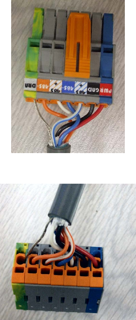
Before SmartSensor Matrix is powered the wires from each sensor cable must be
correctly landed into the plug-in terminals (refer to Figure 2.5 and 2.6).
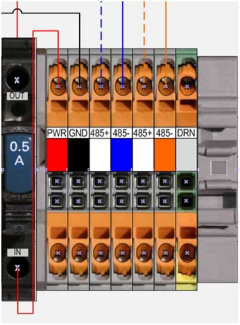
To land the sensor cables, use the following steps:
1. Properly strip back the cable jacket and shielding on the service end of the
cable.
2. Open the insulation displacement connector using a screwdriver. Insert the
wire leads into the bottom side of the plug-in terminal according to the color
code show in the following table and Figure 2.4. Make sure the wires are
bottomed in the terminal.
3. Close the insulation displacement connector using a screwdriver. The plug-in
terminals will automatically displace the insulation and complete the
electrical connection. (There is no need to manually strip the insulation on
the end of each wire.)
The insulation displacement connector plugs are keyed from left to right. The blue
socket can be used to visually see which plug goes into which terminal block. On
the leftmost terminal block, the PWR connection is blue (not gray like the others).
On the next terminal block, the GND connection is blue. The blue connection
continues to move one connection to the right as you move from left to right.
Wire Color
Signal
Red
DC+
Black Common for Power and Communication
White with blue stripe
Command and Control 485+ (Sensor Port 1)
Blue
Command and Control 485- (Sensor Port 1)
White with orange stripe Detection Call 485+ (Sensor Port 2)
Orange
Detection Call 485- (Sensor Port 2)
Bare metal
Drain
Figure 2.5 – Cable Wiring Color Code
31
Figure 2.6 – Color Label on Plug-in Terminals
Figure 2.7 – Opening View of Plug-In Terminal
32
Figure 2.8 – Sensor Cable Terminal Block
33
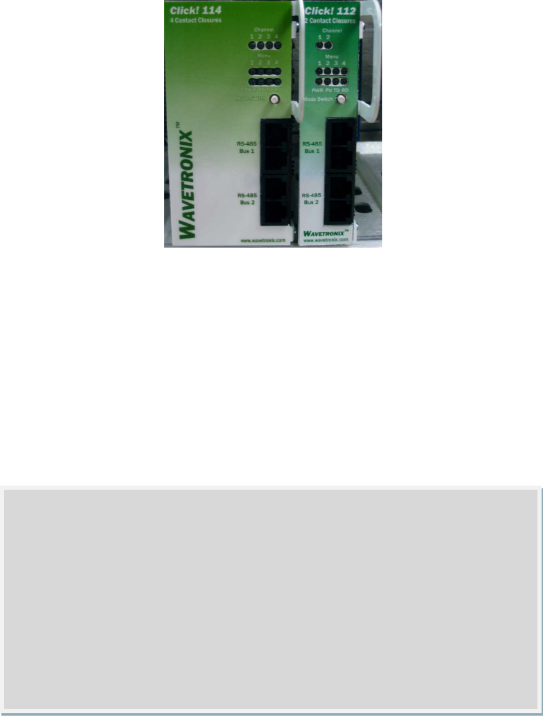
Configure Contact Closure Communications
Each SmartSensor Matrix unit communicates to standard traffic cabinets using
Click! 112/114 detector rack cards. During real-time operations up to four
channels from each sensor can be signaled to a Click! 114 (or to a pair of Click! 112
units daisy-chained together).
Figure 2.7: Click! 112/114 Rack Cards
The rack cards are simple to setup. The cards have been pre-configured using DIP
switches to communicate at 57.6 kbps (the baud rate for SmartSensor Matrix). DIP
switches have also been used to select a group of input channels coming from
SmartSensor Matrix to signal on the Click! 112/114 output channels. The factory
default setting for the Input Mapping switches selects channel group 1.
On a Click! 114 channel group 1 comprises input channels 1-4. When this channel
group is selected; input channel 1 will be mapped to output channel 1, input
channel 2 will be mapped to output channel 2, input channel 3 will be mapped to
output channel 3, and input channel 4 will be mapped to output channel 4.
Note
If you have space in your detector rack, Wavetronix typically recommends
using a 4-channel card. This simplifies the installation process and allows you
to us all four channels from SmartSensor Matrix. If you have a detector rack
that only accepts 2-channel cards (e.g. 170/2070 controller types), then of
course this is your best option. Daisy chain pairs of 2-channel rack cards
together in order to receive all four channels from each sensor. If you do not
have a detector rack in your cabinet, contact Wavetronix technical services for
assistance.

34
On a Click! 112 channel group 1 comprises input channels 1-2, where input channel
1 will be mapped to output channel 1 and input channel 2 will be mapped to output
channel 2. In order to map input channel 3 to output channel 1 and input channel 4
to output channel 2, you will need to select channel group 2. There are three ways
to select channel group 2: using DIP switches, using the Mode Switch on the
faceplate, or using Click! Supervisor.
The DIP switches override the Mode Switch and Click! Supervisor, so if you are
planning on using either the Mode Switch or Click! Supervisor then you will need to
first check that the DIP switches are set to allow for software configuration.
One benefit of using DIP switches to select the channel group is that if you ever
have a field service call and need to replace a Click! 112, all you need to do is
match the pattern of the DIP switches on the card you are replacing. This paradigm
will even work in situations where the old rack card will not even power up.
On the other hand, a benefit of using the software configuration is that you can
remotely manage the configuration of the cards (assuming you have interconnect to
the traffic cabinet and a Click! 301 or equivalent device on the Command and
Control Bridge). In this paradigm, it becomes the responsibility of the traffic
manager in the operations center to keep a record of how each card was
configured.
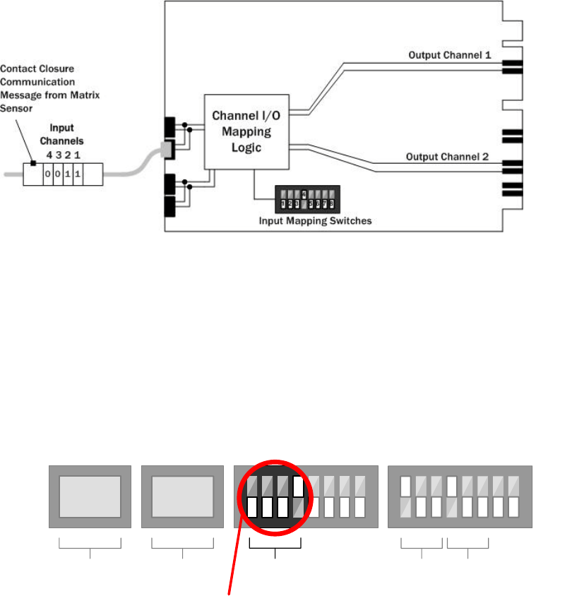
Tip
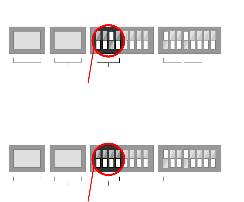
The status of SmartSensor Matrix output channels are sent using a contact
closure serial communications message (see Figure 2.8). Bits within the
message are dedicated to channels 1, 2, 3, and 4. If the designated bits are
set to 1 the associated channel is on (contact closed on rack card), and if they
are set to 0 the associated channel is off (contact open on rack card). When
the serial message sent by a SmartSensor Matrix reaches a rack card the
sensor output channels are now considered rack card input channels. It is then
the job of the rack card to relay the status of the input channels (sensor output
channels) to the selected rack card output channels.
35
Figure 2.8: Symbolic Representation of Click! 112 I/O Channel Mapping
By default the DIP switches of a Click! 112/114 will be set as seen in Figure 2.9.
On a two-channel card this default setting selects, Matrix output channels 1 & 2 for
output. To select channels 3 & 4 move switch 4 down and switch 3 up as shown in
Figure 2.10. To make the channels software configurable, set switches 1-4 down as
shown in figure 2.11
No load
S2 S3 S5
On
Off
123
4
5678
1
2 3
4
5678
Contact Type Switches Baud Rate Switches
Channel
1 & 2 Channel
3 & 4 Bus
1Bus
2
No load
On a 2-channel card: selects Matrix channels 1 & 2 for output
Channel
Group
S4
Input Mapping Switches
On a 4-channel card: selects Matrix channels 1 through 4 for output
Figure 2.9 – Default Position of S4 – Input Mapping Switches
36
No load
S2 S3 S5
On
Off
1 2 4
3
5678
1
2 3
4
5678
Contact Type Switches Baud Rate Switches
Channel
1 & 2 Channel
3 & 4 Bus
1Bus
2
No load
On a 2-channel card: selects Matrix channels 3 & 4 for ouput
Channel
Group
S4
Input Mapping Switches
Figure 2.10 – Position of S4 – Input Mapping Switches to Select Matrix channels 3 & 4
No load
S2 S3 S5
On
Off
1
2
43 5 6 7 8
1
2 3
4
5678
Contact Type Switches Baud Rate Switches
Channel
1 & 2 Channel
3 & 4 Bus
1Bus
2
No load
Makes channel group selection software configurable
Channel
Group
S4
Input Mapping Switches
2
Figure 2.11 – Position of S4 – Input Mapping Switches to Make Channel Group Software Configurable
At a maximum each sensor uses one 4-channel card or two 2-channel cards for
normal operations. This means that a standard 4-approach stop bar detection
system can be accommodated by a 16-channel detector rack. Use the following
steps to setup the contact closure rack cards for each sensor.
1. Plug all the cards into the detector rack. This will provide power.
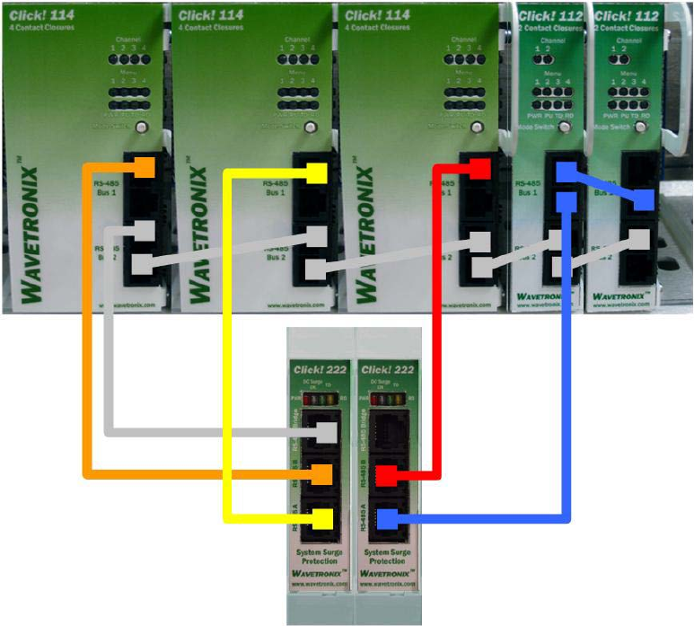
Steps 2-5 are used to connect the isolated detection call links used for real-time
traffic control.
2. Run a long 6-foot patch cord from the Click! 222 RS-485 A port to a Bus 1
port on the appropriate rack card.
3. Run a long 6-foot patch cord from the Click! 222 RS-485 B port to a Bus 1
port on another rack card.
4. If using 2-channel rack cards, use a short 8-inch patch cord to share BUS 1
between cards dedicated to the same sensor. Also, configure one card to
use Matrix channels 1 & 2 and configure the other card to use Matrix
channels 3 & 4.
5. If you have more than 2 sensors in your system, reuse steps 2-4 to connect
Bus 1 for all remaining rack cards.
37
Figure 2.8 – Surge-to-Rack Card Patch Wiring
Steps 6-7 are used to connect the Command and Control Bridge used for shared
access between all sensors, rack cards, and other Click! devices.
6. Run a long 6-foot patch cord from one of the Click! 222 Bridge ports to Bus
2 of the rack cards.
7. Use the short 8-inch patch cords to create a daisy-chain that shares Bus 2
between all of the rack cards. Bus 2 will be used for command and control.
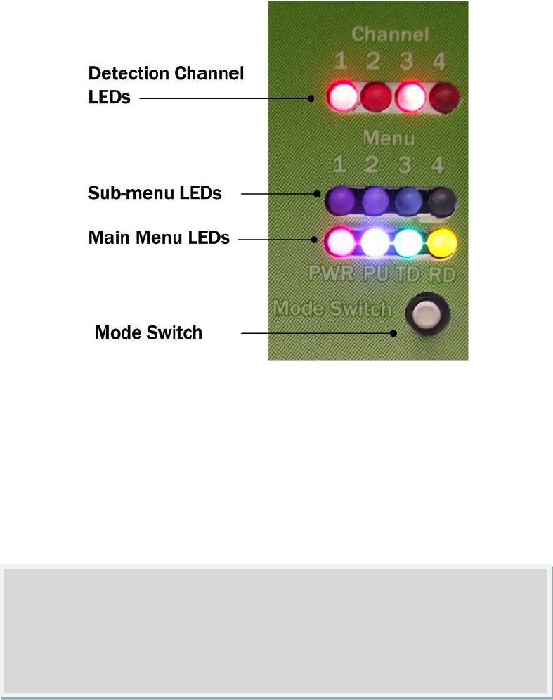
Once you have completed the wiring, check the main menu LEDs. The red PWR LED
should be on indicating that the card is powered and in normal operating mode. In
normal operating mode you will observe the following:
• The green TD LED will activate whenever the card transmits serial
communications.
• The yellow RD LED will activate whenever the card receives serial
communications.
• The red detection channel LEDS (on top) will light up when a call is placed
on the corresponding contact closure output channel.
38
Figure 2.12 – Click! 112/114 Menu
The rack cards are also fail safe. This means that when a sensor does not receive
communications from a sensor within 10 seconds the rack card outputs will all
active. Normally, a SmartSensor Matrix unit will send 10 contact closure messages
per second. In other words, the rack card will go into fail safe mode after 100
messages have gone undetected by the rack card. All the detection channel LEDs
on the faceplate will also light up when a rack card is in failsafe mode.
For additional information about Click! 112/114 rack cards consult Appendix D.
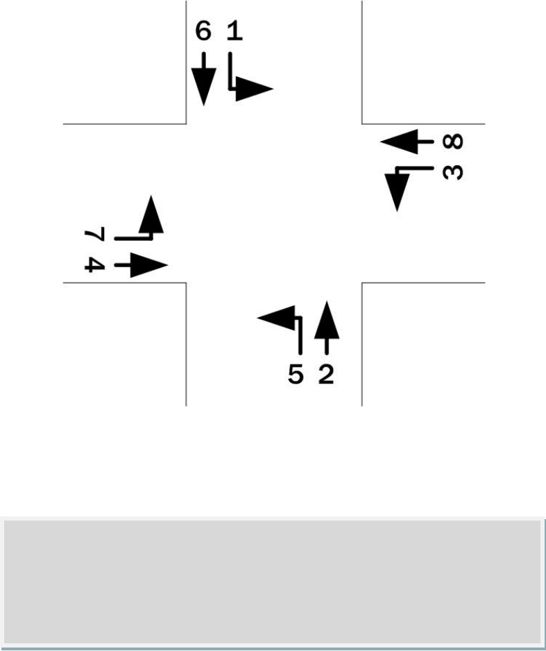
Once the Click! 112/114 rack cards are installed, you will need to make sure that
each detector rack channel is properly mapped to correct traffic phase in the traffic
controller. The general NEMA standard for 8-phase numbering is presented in
Figure 2.13. In practice, many intersections will not have 8 phases and in some
cases they may not even follow the NEMA convention. Check the plans in the traffic
signal cabinet to verify how the phases are numbered at each intersection.
Note
Detection call messages are sent by SmartSensor Matrix 10 times per second.
The latency from transmission by the sensor to actuation on the backplane of
the rack card is less than 3.5 milliseconds.
39
Figure 2.13 – Standard NEMA 8-Phase Number Scheme
Phases 1, 2, 5, and 6 are often used for the “main” street and phases 3, 4, 7 and 8
are often used for the “side” street as shown in Figure 2.13.
Since each Matrix unit often detects both the left-turn phase and the through-
movement phase for a single approach, the associated rack card will have often
have channels that correspond to one of the following phase (ф) pairs: ф2 and ф5,
ф6 and ф1, ф4 and ф7, ф8 and ф3.
NEMA TS2, 2070, and other advanced traffic cabinet systems usually allow
software programming of the detector card channel outputs to traffic phases via a
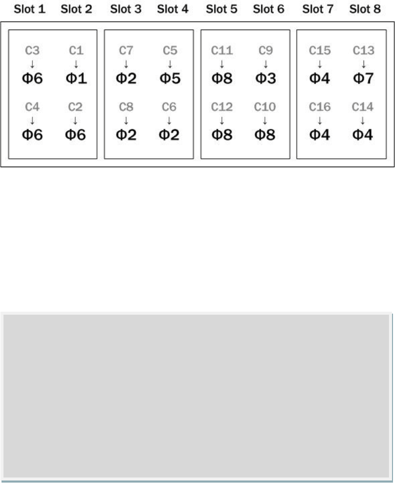
channel-to-phase mapping grid in the controller menu. Figure 2.14 illustrates how
the detector channels 1 to 16 of a NEMA TS-2 rack can be assigned to the standard
8-phases using four Click! 114 cards. The rack card slots are numbered across the
top and the channel positions are represented by the gray labels C1 – C16.
Note
In the chapter on SmartSensor Manger Matrix Tools, you will find a section
about Rack Card Tools which explains how the channel to phase mapping can
be verified with or without the sensors installed.
40
Figure 2.14 – NEMA TS-2 Rack Channel to Traffic Phase Example
In Figure 2.14, four channels are used from each SmartSensor Matrix unit. In this
example, channel 1 from the first sensor is mapped to traffic phase 1 (left-turn
phase on main street). Channels 2, 3, and 4 from the first sensor are mapped to
traffic phase 6. This represents a case where detections from three through-
movement lanes are brought in separately. This type of lane-by-lane detection is
beneficial in some situations. Wavetronix typically recommends the use of 4-
channel cards in racks that will accommodate them, because it offers greater
flexibility of signaling contact closures.
Figure 2.15 illustrates how the detector channels 1 to 8 of a NEMA TS-1 rack can be
assigned to the standard 8-phases using four Click! 112 cards. The rack card slots
are numbered across the top and the channel positions are represented by the gray
labels C1 – C8. This example has the economy of only using four rack slots, but it
does not provide lane-by-lane signaling of the through-movement for cases where
there are multiple through lanes. If you are using a rack with a two-channel
dominant scheme (Four channel cards are not allowed and channels 1 and 2 are in
Note
The channel positions in Figure 2.14 are representative of their arrangement
when two-channel cards are used, even though four-channel cards are
depicted in this example. In reality, all the channels of a four-channel rack
card are signaled through the backplane contacts connected into the in the
even numbered rack slots. NEMA TS-2 channel order is based upon a four-
channel dominant scheme, instead of two-channel dominant scheme. A four
channel dominant scheme will allow two-channel or four-channel cards to be
inserted, but the numbering is based upon a four-channel card. This is why
channels 1 and 2 are in slot 2, instead of slot 1.
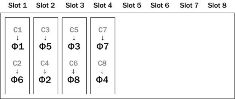
41
slot 1), you can provide lane-by-lane signaling by using two Click! 112 cards for each
sensor. Each pair of Click! 112 cards are daisy chained together.
Figure 2.15 – NEMA TS-1 Rack Channel to Traffic Phase Example
With NEMA TS1 and other legacy systems the programming is often done via a
wiring panel on the side of the controller cabinet. With wired systems you will need
to verify that the wiring on the detector programming panel provides the proper
mapping from the rack channel outputs to the controller input wires dedicated for
ф1-ф8 detector calls.
42
Part II
Using SmartSensor Matrix
43
Installing SmartSensor Manager Matrix Configuration Tool
In this Chapter
Wavetronix Configuration Toolkit
Installing SSMMX
Microsoft .NET Framework
The SmartSensor Manager Matrix (SSMMX) software enables users to configure and
interact with the SmartSensor Matrix (SS225). This software comes preloaded on
the Wavetronix Configuration Tool. This chapter gives an overview of the toolkit.
Also if you are not using the toolkit, or if you would also like to install SmartSensor
Manager Matrix on other devices, this chapter explains how you can get SSMMX up
and running.
Wavetronix Configuration Toolkit
The Wavetronix configuration toolkit is available for reliable and convenient
management of Wavetronix stop bar detection systems. The toolkit includes:
• A portable system link
• A handheld configuration device
• SmartSensor Manager Matrix and other Wavetronix configuration software
The portable system link will convert the wired or wireless serial data to RS-485 and
then send it to all devices on shared multi-drop communication bus on the PCU in
order to allow command and control of all SmartSensor Matrix units from a single
access point.
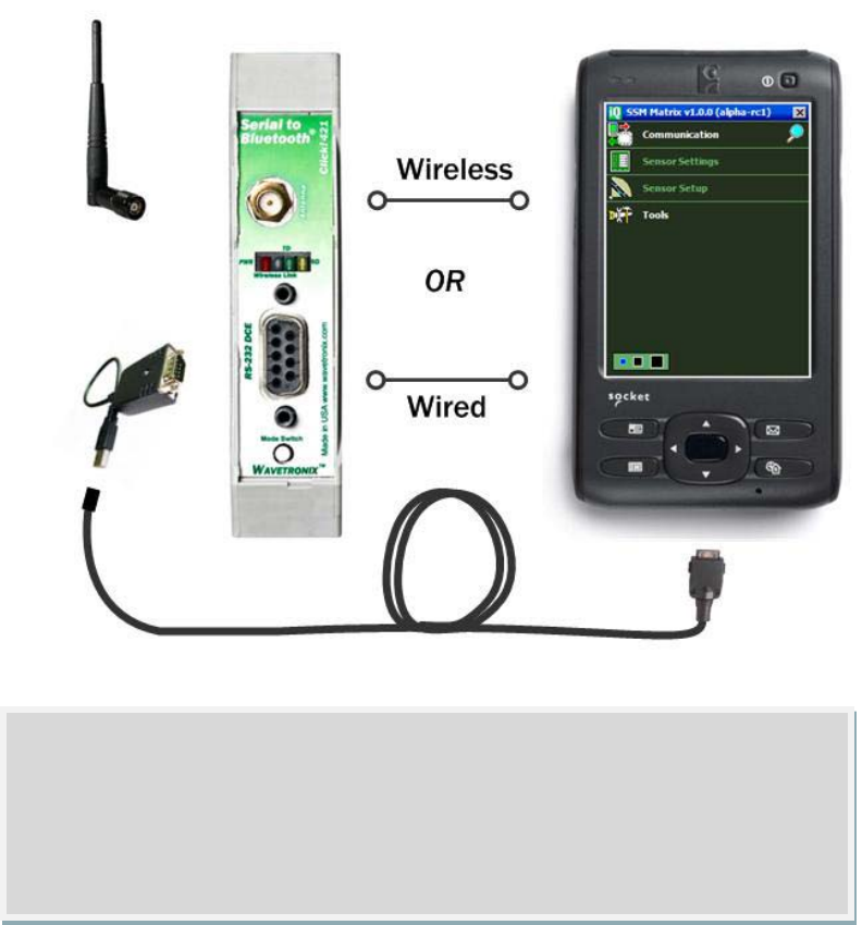
The portable system link (Click! 421) provides both a wired and wireless serial
connection to the handheld configuration device. The wired connection is made
using a USB-to-serial convertor and a USB adapter cable.
The wireless connection is made via preset Bluetooth serial link. A whip antenna
can be attached to the Click! 421 to increase the roaming distance and reliability of
the serial link.
The handheld device is lightweight for extended use outdoors and its screen has
provides for excellent viewing in bright outdoor settings.
44
Figure 3.1 Wavetronix Configuration Toolkit
To attach portable system link:
1. Rock the Click! 421 DIN rail mounted device onto the green T-bus expansion
slot to the left of the gray T-bus connector.
2. Make a serial connection between the DIN rail mounted device and the
handheld. In the case of a wired connection, you will need to physically
connect the serial cable from the handheld device. You can add a USB
extension cable to increase the length of you run is necessary.
If you wish to establish a wired connection with a laptop computer instead of the
handheld device, use the laptop’s native RS-232 serial port to connect to the Click!
421. Or a USB-to-serial convertor if the laptop does not have an RS-232 serial port.
You may also wish to establish a Bluetooth connection from your laptop to the Click!
421. To do so, consult your laptop’s software guidelines on how to discover
Bluetooth devices and configure a Bluetooth serial connection.
Note
The Wavetronix Configuration Toolkit can also be used to configure
SmartSensor Advance, SmartSensor HD, and a host of Click! devices. For
example, the Toolkit also comes pre-loaded with Click! Supervisor to allow
software management of Click! 112/114 rack cards.

45
The toolkit will also come with a RJ-11 patch cord with a pigtail on one end. The
pigtail is wired to the RS-485 screw terminal on the Click! 421 and can be used to
patch into RJ-11 sockets on the rack cards or PCU for troubleshooting.
Installing SSMMX
The SSMMX software is contained on a CD that is shipped with each sensor; and it
can be downloaded at http://portal.wavetronix.com. If you are unable to login, or
you do not have a username, call Wavetronix Technical Services at 801-764-0277
for assistance.
SSMMX can be run on a Windows® PC or on the handheld of the configuration
toolkit (It is not supported on other Windows® CE devices). Everything needed to
install SSMMX to a PC is contained in the SSMMX Setup.exe file.
Follow these steps to install SSM MX on a PC:
1. Place the CD in the CD drive.
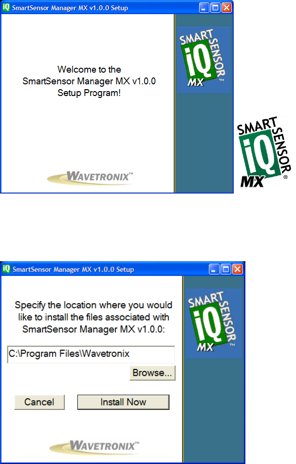
2. Double click the Setup.exe icon listed in the contents of the CD. This
executes a setup program that will copy all the necessary files to the hard
drive and place icons in the Start menu and on the desktop of the PC or
laptop (see Figure 3.2).
Note
You must have administrator rights to run the setup program.
Note
You can check the Wavetronix portal to ensure that you have the latest version
of SmartSensor Manager Matrix. To access the portal, open a web browser and
go to portal.wavetronix.com. Login with the username “guest” and password
“wavetronix.” In the menu on the left side, select SmartSensor Products. The
latest version of the software, along with the release date, will be listed under
SS225 Software.
46
Figure 3.2 – SSMMX Setup Wizard (New Screenshot Needed)
3. Select an installation location. The default location provided is normally
“C:\Program Files\Wavetronix.” Click Browse to choose another location
(see Figure 3.3).
Figure 3.3 – Location to Be Installed (New Screenshot needed)
4. Click the Install Now button.
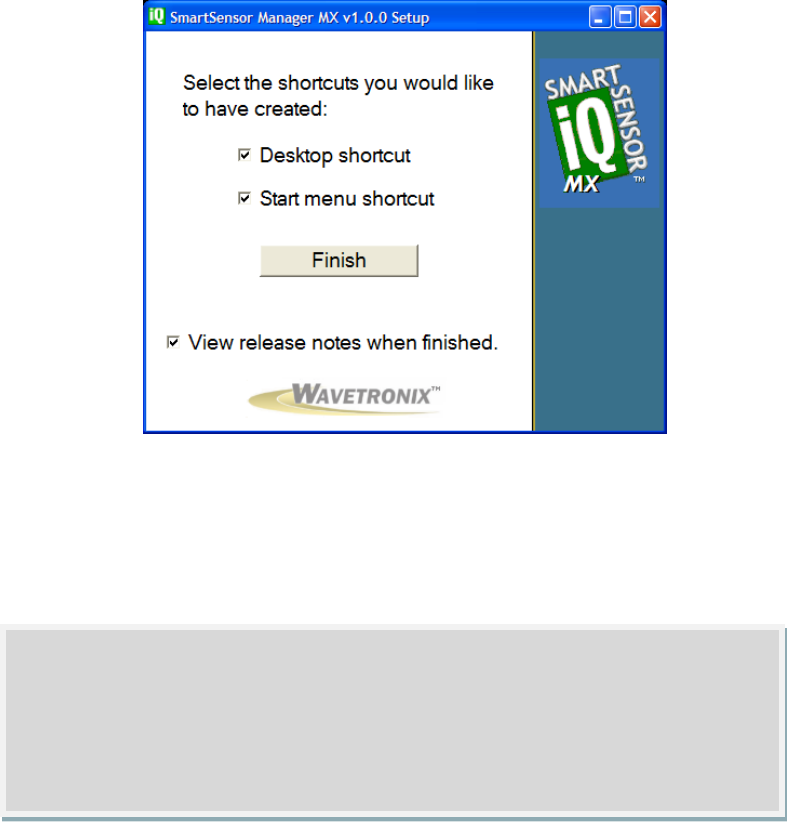
5. After SSMMX is installed, you can create shortcuts to the SSMMX software
on the desktop and in the start menu using the corresponding checkboxes
(see Figure 3.4). If no shortcuts are desired, uncheck the corresponding
boxes.
47
Figure 3.4 –Shortcut Options (New Screenshot Needed)
6. Click the View release notes when finished checkbox to view the SSMMX
release notes. The release notes contain additional information about the
current version of the SSMMX software. A PDF reader program (i.e. Adobe
Acrobat Reader) is required to view the release notes.
7. Click Finish to complete the setup process.
Use these steps to install SSMMX on a Pocket PC® (Windows Mobile):
1. Ensure the Pocket PC is connected to the PC and synced.
2. Click on the SSMMX Setup.exe file to run the setup program on the host
computer. The SSMMX Setup Wizard will automatically check the host
computer to see if Microsoft ActiveSync is installed (ActiveSync is a program
that is used to communicate with a Pocket PC device). If the ActiveSync
program is found, the option of installing SSMMX to a Pocket PC device will
become available.
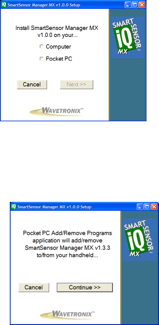
3. Click the Pocket PC checkbox and then the Next>> button to install SSMMX
on a connected Pocket PC device (see Figure 3.4). If both the Computer and
Pocket PC boxes are checked, the setup program will first install the SSMMX
software to the PC.
Note
SSMMX is designed to display text with Normal Size display resolution (96
DPI). If your text is too big and does not display properly, you can edit the
Advanced Display property settings on your PC to reduce the display resolution
from 120 DPI down to 96 dpi.
48
Figure 3.5 Destination Selection (New Screenshot Needed)
4. Click Continue>> to start the Pocket PC installation process (see Figure 3.6).
The setup program runs the Add/Remove Programs application for
Windows handheld devices. If a Pocket PC device is connected to the
computer, Add/Remove Programs will immediately begin installing SSMMX
on the Pocket PC device. If a Pocket PC device is not connected to the
computer, SSMMX will be downloaded the next time a Pocket PC device is
connected to the computer.
Figure 3.6 - Adding SSMMX to a Pocket PC (New Screenshot Needed)
5. Click OK once the download is complete.
49
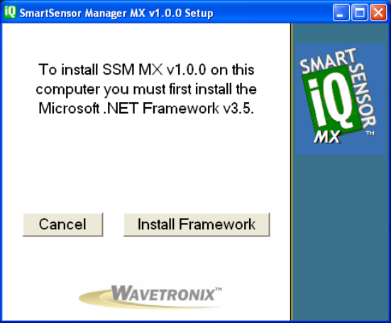
Microsoft .NET Framework
The SSMMX setup program will automatically detect whether Microsoft .NET
Compact Framework v2.0 (screenshot says v3.5, but actually v2.0) is installed on
your PC. If it is not installed, you will be prompted to install it (see Figure 3.7).
Figure 3.7 – Microsoft .NET Framework V2.0 Prompt (New Screenshot Needed)
Use the following steps to install Microsoft .NET Framework:
1. Click the Install Framework button.
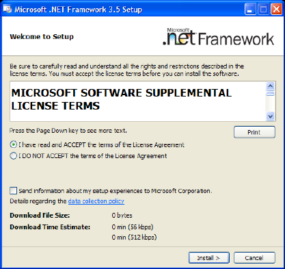
2. Click the I Agree radio button when the License Agreement appears (see
Figure 3.8).
3. Click Install. A window will appear stating that the .NET Framework has been
installed successfully.
50
Figure 3.8 – License Agreement (New v2.0 Screenshot needed?)
4. Click OK and you will be returned to the SmartSensor Manager Matrix Setup
program.
51
Communication
In this Chapter
Serial Connection
Internet Connection
Virtual Connection
Address Book
Viewing Connection Information
Uploading the Sensor’s Embedded Software
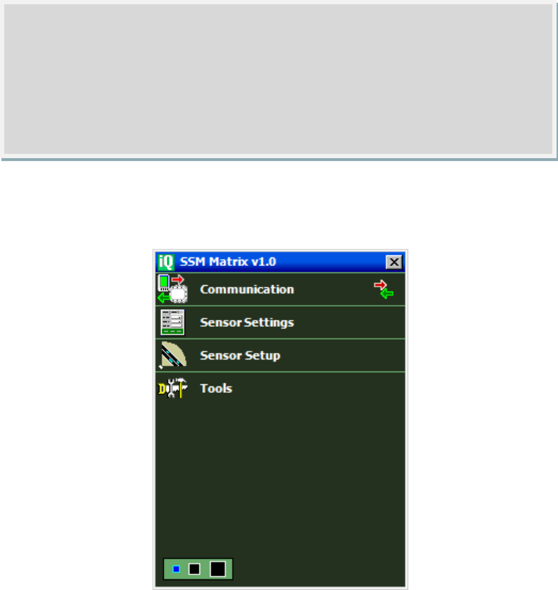
Once the SmartSensor Matrix units are installed, use the SSMMX software to
change settings, view data, and configure the sensors to the roadway.
First, connect your configuration computer to the Wavetronix Stop Bar Detection
System command and control bus. Next, launch SSMMX by either clicking on the
icon that was placed on your desktop or clicking the icon found in the Start menu.
The SSMMX main screen shown in Figure 4.1 will appear.
Figure 4.1 – SSMMX Main Screen (New Screenshot needed)

52
To interact with and configure Matrix sensors with SSMMX, connect to the sensor
through one of the following three types of connections:
a serial connection;
an Internet connection, made using an IP address and a serial to Ethernet
converter;
or a virtual connection, which can be made for convenience in learning and
demonstrating SSMMX functionality.
Serial Connection
1. Click on Communication to access the Communication window (see Figure
4.2).
2. Select the Serial tab.
3. Set Port and Timeout to the desired settings.
4. Select the type of search you would like to perform using the radio buttons
(Full or Quick).
5. Click the Search button. Please wait up to 30 seconds while the sensors on
your network bus are discovered and listed. (You can click Cancel, if the
sensor of interest has already been listed.)
6. Click on the desired row from the list to select a sensor. The list presents
the Sensor ID, Location, and Approach fields of each sensor discovered.
7. Click the Connect button. When a connection is established you will be
directed back to the home page.
Tip
Click the magnifying glass icon on the right side of the communication link of
the main SSMMX page to help expedite completion of a connection using the
most-recently-used parameters. For example, if your most recent connection
was an Internet connection, click on the magnifying glass to bring up the
Internet tab with the last IP Address, port, and timeout values specified. When
the page appears, you will notice that SSMMX is searching at the selected
destination using the last type of search (Quick or Full) that you selected. The
magnifying glass will only appear when there is no connection currently
established.
Tip
If you are using SSMMX on a laptop computer, you can use the panel in the
lower-left of the main screen to change the size of the program on your
computer. By default the smallest size is selected. If you click on the larger
rectangles you can increase the size of the program by two or three times.
53
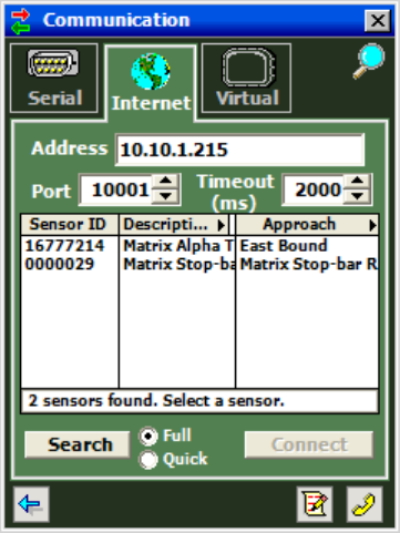
If you select a Full search, the search engine will go through an exhaustive process
to find all SmartSensor Matrix units on the selected network bus. This process will
reassign each sensor on the network bus a new communication time slot, and can
take up to 30 seconds.
A Quick search is much faster because it requests that each sensor respond using a
previously assigned communication time slot. However, a quick search should not
be used the first time you connect to a network, or if you have added a new sensor
to an existing network, because by default sensors may have conflicting time slots.
The first time you connect to a sensor network bus, the default Sensor ID of each
discovered sensor will be unique (based upon the last seven digits of the serial
number). However, the default names in the Location and Approach text fields will
all be the same.
To setup network names (e.g. Description, Location, and Approach) in an orderly
fashion, it is recommended that the circuit breaker switches be used to selectively
power sensor. First, power only one sensor and enter its naming information. Then
repeat this process to power additional sensors, one at a time.
Figure 4.2 – Serial Connection Screen (New Screenshot needed)
Tip
It is recommended that you use labeling on the service end of each
SmartSensor Matrix cable (see Figure 1.8). If you have not already labeled the
service end of the sensor cable, you may be able to do so now. If not, you may
need to rely upon traffic patterns to sort out the sensors.
54
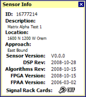
Once you have selected a sensor from the device list, you can click again on that
row to bring up a Sensor Info popup (see Figure 4.3). To bring up the Sensor Info
popup, you can also click on the sensor icon that appears in the upper right corner
of the screen (see Figure 4.2).
Figure 4.3 – Sensor Info Popup
The Sensor Info popup is also available on the Internet Connection and Virtual
Connection screens. This screen lists the following sensor settings and version
information:
• Sensor ID – Unique Address (by default based upon the last seven digits of
the serial number).
• Description – User-definable 32 character text field use to describe the
sensor. Can be used to indicate items such as the application (e.g. stop bar
detection) or GPS coordinates.
• Location – User-definable 32 character text field typically describing the
intersection where the sensor is located (e.g. “Main & Center – Anytown
USA”).
• Approach – User-definable 32 character text field that typically indicates
which approach of the intersection the sensor monitors (e.g. “EB Main
Traffic”).
• Sensor Version – Overall sensor product version which represents a released
combination of the DSP, Algorithm, FPGA, and FPAA subcomponent
versions.
• DSP Rev – DSP code version as a date (YYYY-MM-DD).
• Algorithms Rev – Algorithm code version as a date (YYYY-MM-DD)..
• FPGA Version – FPGA version as a date (YYYY-MM-DD).
• FPAA Version – FPAA version as a date (YYYY-MM-DD).
The Sensor Info popup also has a Signal Rack Cards toggle switch. When the switch
is on, any rack cards connected to this sensor will identify themselves by flashing a
blink sequence on the main menu LEDs of the rack card (see Figure 2.10).
Internet Connection
The SmartSensor Matrix can be connected to the Internet allowing access to the
sensor from anywhere with Internet access. Below is a list of three ways to connect
the SmartSensor to the Internet:
55
1. Serial to Ethernet Converter – The SmartSensor Matrix can be connected to
a local area network (LAN) by using a serial to Ethernet converter. As an
option, the SmartSensor Matrix can be shipped with a Click! 301 serial to
Ethernet converter that is Internet addressable, which makes it possible to
connect to the sensor from anywhere the adapter’s address is accessible.
2. Serial to 802.11b Wireless – The Click! 401™ is a serial to 802.11b
converter that provides serial devices with an IP address on a wireless
802.11b network.
3. Internet Service Providers – Cellular providers of wireless internet services
maintain networks in most metropolitan areas in the United States and
coverage continues to expand. The SmartSensor Matrix can be equipped
with optional external modems—for example, CDMA, GMS or GPRS— and
assigned an Internet address on these networks. (Please test that
SmartSensor Matrix will work with a particular manufacturer’s modem, or
contact Wavetronix technical services for assistance and guidance.)
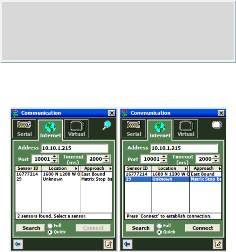
Use the steps below to connect to the SmartSensor Matrix using an Internet
connection:
1. Click on Communication.
2. Click the Internet tab and the Internet setting options will appear (see Figure
4.4).
3. Enter the IP address or URL of the sensor of interest. The IP address
consists of four numbers ranging from 0-255 separated by dots. Enter the IP
address assigned to either the CDMA modem or the Click! 301 serial to
Ethernet converter.
4. Enter the port number assigned to the CDMA modem or the Click! 301 serial
to Ethernet converter in the Port field. This will be an integer value in the
range of 0-65536. The Click! 301 port number automatically defaults to
10001.
5. Select the timeout value.
6. Select the type of search you would like to perform using the radio buttons
(Full or Quick).
7. Click the Search button. Please wait up to 30 seconds while the sensors on
your network bus are discovered and listed. (You can click Cancel, if the
sensor of interest has already been listed.)
8. Click on the desired row from the list to select a sensor. The list presents
the Sensor ID, Location, and Approach fields of each sensor discovered.
9. Click the Connect button. When a connection is established you will be
directed back to the home page.
56
Figure 4.4 – Internet Connection Screen
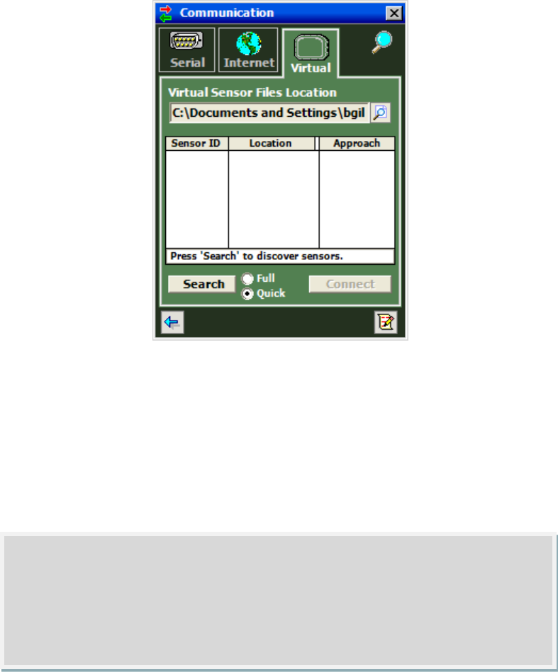
Virtual Connection
A virtual connection allows you to use the SSMMX software without being connected
to an actual sensor. Making a virtual connection can be useful for the following
reasons:
• To view a saved sensor setup file.
• To demonstrate functionality for different applications.
• To review how the soft ware works.
• To play back previously logged traffic. (This feature is not available yet)
To make a virtual connection:
1. Click the Communication button.
2. Select the Virtual tab (see Figure 4.5).
3. Select or create a virtual sensor file (.vsf) by clicking the magnifying glass
icon.
4. Select the type of search you would like to perform using the radio buttons
(Full or Quick).
5. Click the Search button. Please wait up to 30 seconds while the sensors on
your network bus are discovered and listed. (You can click Cancel, if the
sensor of interest has already been listed.)
6. Click on the desired row from the list to select a sensor. The list presents
the Sensor ID, Location, and Approach fields of each sensor discovered.
Click the Connect button. When a connection is established you will be directed
back to the home page.
57
Figure 4.5 – Virtual Connection Screen
Virtual Sensor File
Since a virtual connection is not made to an actual sensor, a virtual sensor file (.vsf)
is used to save the configuration settings much like an actual sensor’s Flash
memory. If you are making a virtual connection for the first time, you will need to
create a virtual sensor file by clicking on the magnifying glass icon and entering a
file name.
Backing up a virtual sensor file will change the file to a sensor setup file (.ssc) that
can be restored to an actual sensor. To convert a sensor setup file to a virtual sensor
file, make a virtual connection and then use the Restore Sensor Setup tool in the
Tools menu. To convert a virtual sensor file to a sensor setup file, use the Back-up
Sensor Setup tool.
Note
When you are connected using a virtual sensor file, changes that would
normally be saved to a sensor’s Flash memory will automatically be saved to
the virtual sensor file.
58
When a connection is made to the SS200, the main menu will appear and all
configuration options will become available (see Figure 4.6).
Figure 4.6 – Main Menu (Connected)
If you have problems connecting:
1. Make sure that all power and communication wiring is correct;
2. Check the Port settings (Port ID).
Connection failure can occur for various reasons; if a failure occurs repeatedly, call
Wavetronix Technical Support at 801-764-0277 for assistance.
Address Book
PLEASE NOTE – The Address Book is still under design. The documentation in this
section will need to be updated once the software is completed. For now this
explanation is just a placeholder.
The Address Book allows you to save device connection settings for future use.
Example
If you wanted to configure channels for a future installation, you could connect
using a virtual connection, create a virtual sensor file and then backup the
configuration settings that you created. After the file is successfully backed up,
the virtual sensor file will change to a sensor setup file and can be restored to
any sensor in the field.
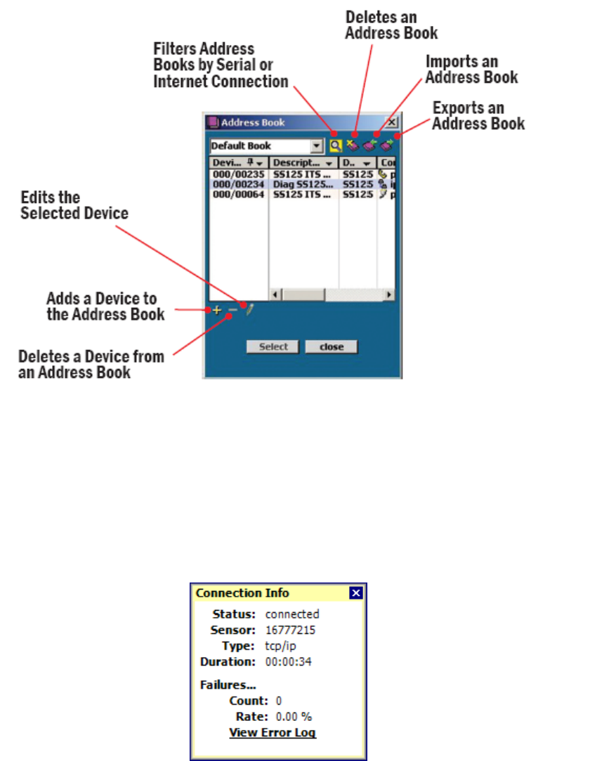
59
Click the Address Book button located at the bottom of the Communication page to
add new connection settings to the Address Book (see Figure 4.7).
Figure 4.7 – Address Book and Address Book Filter (New Figure Needed)
Viewing Connection Info
Once connected, you can view additional information about the connection you
have established by clicking on the moving arrows icon on the top-right of the main
menu page or on the bottom-right of the Communication screen (see Figure 4.8).
These arrows are only visible when there is an established connection.
Figure 4.8 – Connection Info Screen
Below is a list of the information available on the Connection Info screen:
• Status. – Shows that you are connected.
• Device – Shows the Subnet and sensor ID.
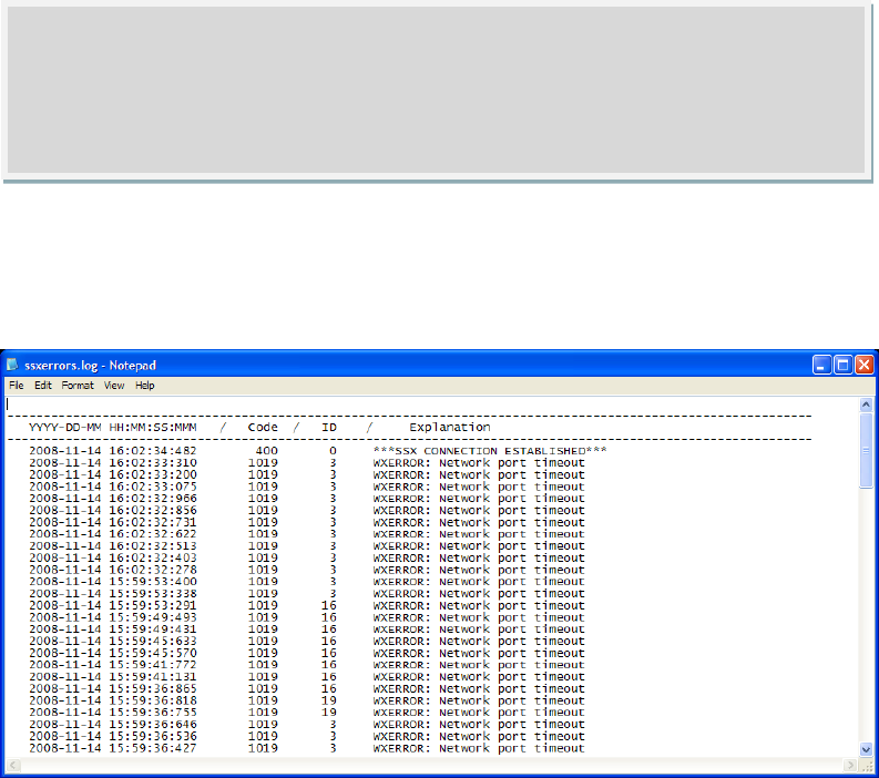
60
• Type – Shows the type of connection and baud rate.
• Duration – Shows how long you have been connected.
• Failures – Shows the amount of failures during the connection, the
percentage rate of failure and a link to the Communication Error Log.
Communication Error Log
The error log contains all errors stored in the sensor’s memory buffer. If you are
having trouble connecting, using the error log may be helpful in the troubleshooting
process. If you continue having trouble, save the error log file and contact
Wavetronix Technical Services.
Click the View Error Log link to view the communications error log (see Figure 4.11).
The error log can also be accessed by clicking on the Error Log icon at the bottom of
the Communication screen.
Figure 4.11 – Error Log
Uploading the Sensor’s Embedded Software
After clicking the Connect button, the soft ware will check to see if your soft ware
version matches the version of the sensor’s embedded soft ware. If a discrepancy is
detected, the Version Control screen may appear asking you to install firmware
upgrades (see Figure 4.12). If you think you have reached this screen in error,
clicking the Recheck button will have the soft ware retry and ensure that there has
not been a communication issue. Clicking the Details button will display the current
Note
The error log is cleared every time you close SSMMX, so if you need to save the
file, do so before shutting the program down.
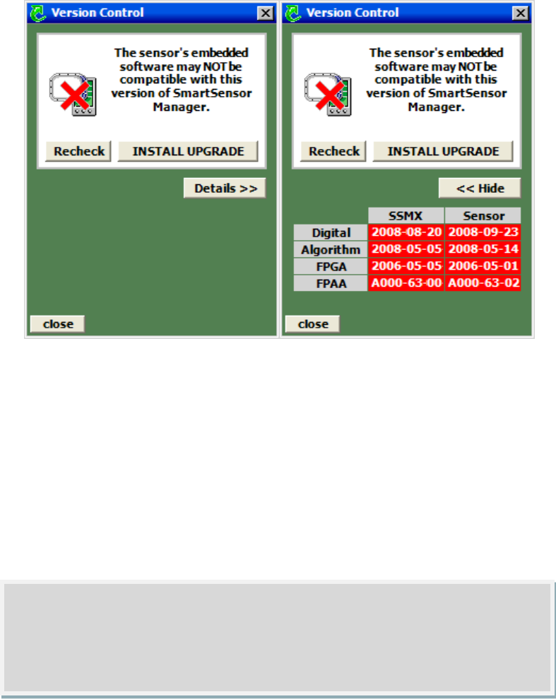
61
sensor and soft ware information. Click the Install Upgrade button to upgrade the
software.
Figure 4.12 – Sensor’s Embedded Software Upgrade (left) and Details Table (right)
Click the Details button to view the firmware versions of both the SSMMX software
and the sensor.
Once the Version Control screen appears, you can do one of the following:
1. Upgrade the sensor’s embedded software by clicking the INSTALL UPGRADE
button.
2. Click the close button and continue the configuration process.
3. Find the version of SSMMX software that is compatible with the sensor’s
embedded software.
If the row marked Digital is highlighted in red, the firmware upgrade may need to be
installed. Compare the Sensor number with the SSMCE number in the Digital row of
the details table. If the SSMMX firmware version date is more recent than the
sensor firmware version date, the firmware upgrade will need to be installed; if the
sensor’s firmware date is more recent than the SSMMX firmware version date, a
warning will appear notifying you that the sensor firmware could be downgraded
(see Figure 4.13).
Warning
Clicking the
close
button and continuing configuration without upgrading may
cause problems with functionality.

62
Figure 4.13 – Sensor Firmware Downgrade
If the downgrade message appears, it simply means that the sensor firmware is
newer than the version of SSMMX that was used to connect to the sensor. The
newest version of SSMMX can be updated by downloading the software from the
Wavetronix Portal.
Click the INSTALL UPGRADE button to install the firmware embedded in SSMMX
onto the SmartSensor Matrix. The Recheck button will query the sensor to see if the
firmware bundled in SSMMX is different than the version running on the sensor.
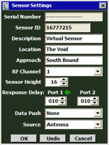
63
Sensor Settings
In this Chapter
Sensor Settings
Click the Sensor Settings link on the main menu to change and save settings on the
sensor.
Figure 5.1 – Serial Settings Window (New Screenshot Needed)
The Sensor Settings window contacts the following fields (see Figure 5.1):
• Serial Number – Contains the sensor serial number and cannot be edited.
• Sensor ID – ID used to uniquely identify all sensors on a multi-drop bus. This
ID is based upon the last seven digits of the Serial Number and cannot be
edited.
• Description – Allows you to enter a description for each sensor. Limited to
32 characters.
• Location – Allows you to enter the intersection location of the sensor.
Limited to 32 characters.
• Approach – Allows you to enter the direction of traffic the sensor is
detecting (e.g. NB, SB, WE, WB). Limited to 32 characters.
• RF Channel – Displays which radio frequency channel the sensor is using.
There are eight RF channels available. Using multiple sensors in close
proximity will require each sensor to be set to a different RF channel (see
the introduction for more information about mounting sensors in close
proximity).
• Sensor Height – The height of the sensor in feet. This value impacts the
performance of the sensor.

64
• Response Delay – This is used to configure how long the sensor will wait
before responding to a message received. This is useful for some
communications devices that are unable to quickly change transmission
direction. The default value is 10 milliseconds. This value can be selected
for both of the sensors ports independently.
• Data Push – Data can be pushed over port 1, port 2, or both. To prevent
data push, select “None”. In many cases, data push will only occur over Port
2 which is typically designated for detection calls (based upon the pre-wired
connections of a PCU).
• Source – In normal use the source is always the radar Antenna. However in
some cases, other sources may be used for demonstrations or evaluations.
When the source is switched to diagnostic, the antenna is not longer used.
Instead a predetermined sequence of traffic will appear. The replay source
is only available if the sensor is equipped with this special hardware.
Note
If for some reason SSMMX connects over the Port that SmartSensor Matrix is
pushing data, the software will continue to poll the sensor for detection call
messages. This will help keep the intersection operating as normal during the
configuration process.
Note
A green arrow is used to show the port over which SSMMX is connected to the
sensor. In many cases, the SSMMX will be connected over Port 1. Port 1 is
usually designated for command and control and is connected to the blue RS-
485 wire pair. However, during troubleshooting or other special cases SSMMX
may connect to the sensor over Port 2. Port 2 is connected to the orange RS-
485 wire pair and is typically used for detection calls.
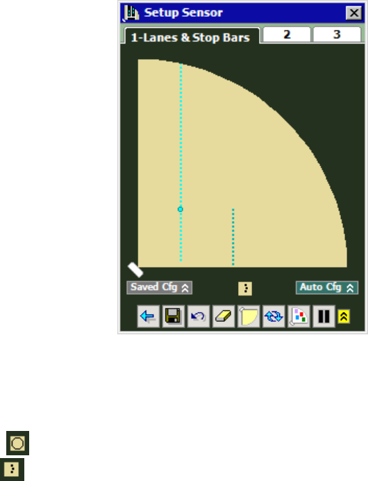
65
Sensor Setup
In this Chapter
Lanes and Stop Bars
Zones and Channels
Verification
The Sensor Setup screen allows provides automatic and manual controls to quickly
and easily configure the sensor to the roadway. Configuration is a three step
process that follows the tabs below the Sensor Setup title bar.
Lanes and Stop Bars
In Step 1 the lanes and stop bars of the corresponding intersection approach are
configured. Lanes, stop bars, and vehicle tracks are shown within the sensor’s 100-
foot 90° degree view (see Figure 6.1). This view has the appearance of a baseball
infield with the sensor icon shown at the position where home base would be.
Figure 6.1 – Lanes & Stop Bars View (Edit Area)
Before any lanes are discovered you will see vehicle tracks in the auto-configuration
view. Vehicle tracks can be represented with or without a track history. To toggle
the track history on or off press the little detection display button below the middle
of the sensor view. When it the track history is on the button will appear like as a
circle . When the track history is off the button will appear as a vertical series of
dots .
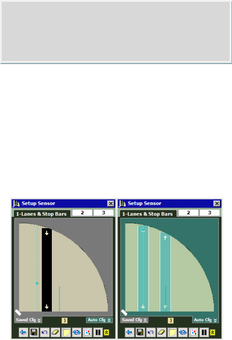
66
When on the Lanes & Stop Bar view there are three display options:
• Edit Area only
• Edit Area with Saved Configuration Overlay
• Edit Area with Automatic Configuration Overlay
Figure 6.1 shows the Edit Area only. The Edit Area shows changes that have been
made within SSMMX, but that have not yet been saved on the sensor. Figure 6.2
shows the Lanes and Stop Bars view with the Saved Configuration Overlay (left) and
the Automatic Configuration Overlay (right). To show or hide these overlays toggle
the Saved Cfg and/or Auto Cfg buttons. These buttons are found below the sensor
view and above the menu bar.
SmartSensor Matrix is constantly running the auto-configuration process in order to
find undiscovered lanes and stop bars.
Figure 6.1 – Lanes & Stop Bars View with Overlays
The menu bar at the bottom of the screen will allow you to perform a variety of
operations during Sensor Setup. Press the yellow up-arrows icon at the right side of
Note
When on the Lanes & Stop Bars view, you only see vehicle tracks. These
tracks are not constrained to lanes, even after you have saved a lane
configuration to the sensor. Vehicle detections are only viewed on the
Verification View.
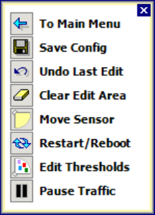
67
the menu bar to open a pop-up view of the Lanes & Stop Bars menu (see Figure
6.2).
Figure 6.2 – Sensor Setup Menu Popup
Use the blue back-arrow to return to the main menu. Click the Save Config button
to save the sensor configuration at any time. To undo the last change in the Edit
Area, click the Undo Last Edit button. To clear all your pending changes, click the
Clear Edit Area. Click the Pause Traffic / Play Traffic button to suspend or resume
movement of vehicle tracks on the screen.
In general, the following order is recommended for completion of Step 1 – Lanes
and Stop Bars.
1. Move Sensor to correct location.
2. Restart Automatic Lane Configuration. Allow the automatic configuration
process to run for several cycles around the intersection (approximately 5 to
10 minutes).
3. Capture Lanes & Stop Bars to Edit Area
4. If necessary, make manual adjustments to the Lane & Stop Bar
Configuration using the Edit Area
5. Save the desired changes to the sensor.
Move Sensor
The sensor is typically used to monitor traffic on one approach of the intersection.
Often the sensor is mounted on the near-side of the approach near the intersection.
In this case the sensor monitors the traffic approaching the stop bar as it travels
towards the sensor. If your sensor is not mounted from this vantage point, click the
Move Sensor Icon until the sensor has moved to the correct corner of the screen.
The sensor will move in the following sequence:
• Bottom left-hand corner - near side of approach monitoring traffic traveling
towards the sensor’s location.
• Top left-hand corner - near side of approach monitoring traffic traveling
away from the sensor’s location.
• Top right-hand corner - far side of approach monitoring traffic traveling
away from the sensor’s location.
• Bottom right-hand corner - far side of approach monitoring traffic traveling.
This sensor placement allows direct line-of-sight to the first left turn lane.
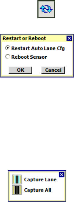
68
Restart Automatic Lane Configuration
When you enter the Sensor Setup screen for the first time, restart the auto-
configuration process to erase auto-configuration information that may have been
gathered before the sensor’s alignment was finalized.
To restart the automatic lane configuration process:
1. Click the Restart or Reboot button
2. Click OK on the Restart of Reboot popup window (see Figure 6.3).
Figure 6.3 – Restart or Reboot Popup
Capture Lanes and Stop Bars to Edit Area
When auto-configured lanes appear they can be captured by clicking on them.
Once a lane is captured it becomes part of the Edit Area. Captured lanes are not
saved to the sensor until after clicking on the Save Config button.
To capture a single lane:
1. Click on the lane once to select it.
2. Click on the lane a second time to bring up the Capture pop-up window (see
Figure
3. Click on the Capture Lane button to capture the selected lane.
Figure 6.4 – Capture Popup
Each lane has its own stop bar. If a stop bar is found for a lane it will be captured
with the lane. If you want to capture all the configured lanes, press the Capture All
button.
Make Manual Adjustments
If necessary the following manual adjustments can be made:
• Add / delete a lane
• Insert / delete a lane stop bar
• Move a lane stop bar
• Insert / delete a lane node
• Move a lane node
• Adjust the width of a lane node
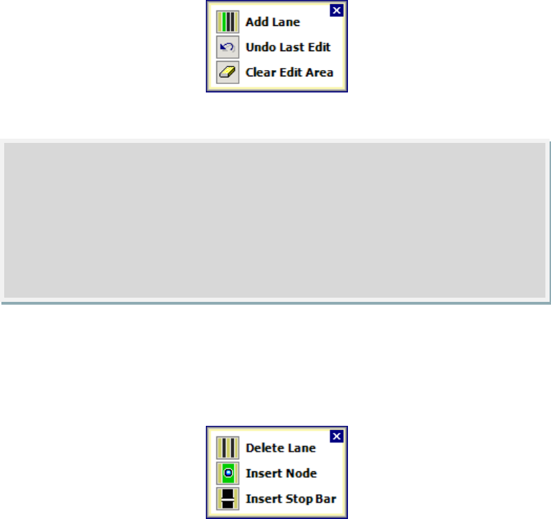
69
• Adjust thresholds
To add a lane:
1. Click in the Edit Area in the vicinity of the lane.
2. Click on the Add Lane option. There are a maximum of ten lanes and lanes
cannot overlap. (You may be able to add an overlapping lane to the edit
area, but you will not be able to save it.)
Figure 6.5 – Edit Area Popup
To delete a lane:
1. Click in the Edit Area to select a lane.
2. Click on the selected lane to bring up the Edit Lane popup.
3. Click on the Delete Lane option of the Edit Lane popup.
Figure 6.6 – Edit Lane Popup
To insert a lane stop bar:
1. Click in the Edit Area to select a lane.
2. Click on the selected lane to bring up the Edit Lane popup.
3. Click on the Insert Stop Bar option of the Edit Lane popup.
To delete a lane stop bar:
1. Click in the Edit Area to select a lane.
2. Click on the stop bar within the selected lane.
3. Click on the Delete Stop Bar option of the Edit Stop Bar popup.
Note
Lanes have a direction shown by white arrows on top of the lane. The lane
direction is dictated by the order of the lane nodes. When a lane is first added
it will only have two nodes. To switch the lane direction, simply click on the
arrows. Before you save the configuration, check to make sure that all the
arrows are pointing in the correct direction.
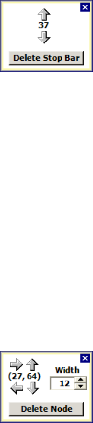
70
Figure 6.7 – Edit Stop Bar Popup
To move a lane stop bar:
1. Click in the Edit Area to select a lane.
2. Click on the stop bar within the selected lane.
3. Click on the arrows to move the lane stop bar in the desired direction. The
number between the arrows indicates the distance from the lane’s end
node.
To insert a lane node:
1. Click in the Edit Area to select a lane.
2. Click on the selected lane in the vicinity of the desired node to bring up the
Edit Lane popup (see Figure 6.6).
3. Click on the Insert Node option of the Edit Lane popup. A lane can have a
maximum of six nodes.
To delete a lane node:
1. Click in the Edit Area to select a lane.
2. Click on the selected lane in the vicinity of the desired node to bring up the
Edit Node popup (see Figure 6.8).
3. Click on the Insert Node option of the Edit Lane popup. A lane can have a
maximum of six nodes.
Figure 6.8 – Edit Node Popup
To move a lane node:
1. Click in the Edit Area to select a lane.
2. Click on the selected lane in the vicinity of the desired node to bring up the
Edit Node popup (see Figure 6.8).
3. Click on the arrows to move the node in the desired direction. The
numbered pair (x,y) between the arrows indicates the distance within the
sensor’s view. The x-value indicates the distance from the right edge of the
sensor’s view in (feet). The y-value indicates the distance from the left edge
of the sensor’s view (In feet).
Adjacent lane nodes can be placed to follow the curve of a turn movement.
However there is a limitation to the amount of curvature that is acceptable (see
Figure 6.9). The departure from a straight path cannot exceed 45 degrees. While
you will be able to allow move the node anywhere on the screen you will get a
notification that the “lane configuration is invalid” if the allowable limits are
exceeded.
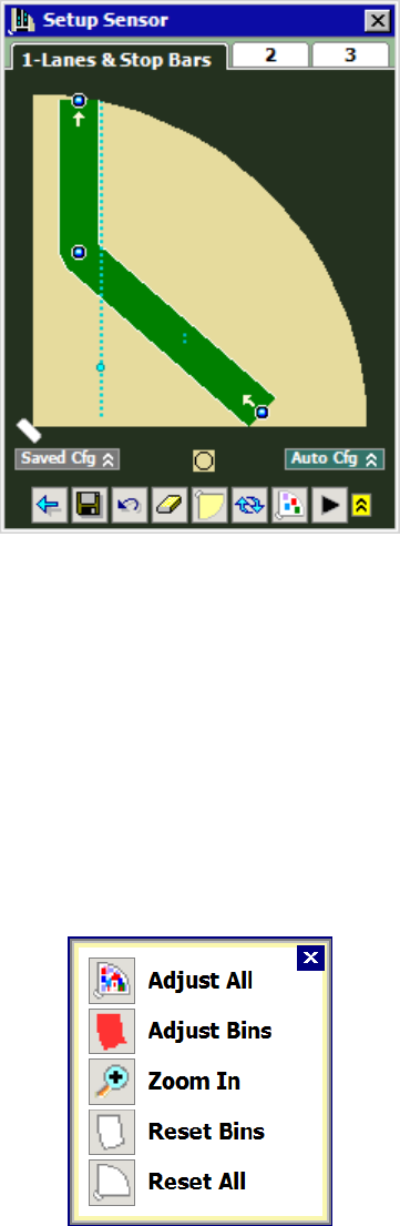
71
Figure 6.9 – Example of an Invalid Lane Configuration
To adjust the width of a lane node:
1. Click in the Edit Area to select a lane.
2. Click on the selected lane in the vicinity of the desired node to bring up the
Edit Node popup (see Figure 6.8).
3. Click on the Width Edit Box up/down bumpers to change the width of the
node (in feet). Adjusting the node width will impact detection search area
for that lane.
To adjust thresholds:
1. Click on the Edit Thresholds Button.
2. Click within the sensor view. This will bring up the Sensitivity popup (see
Figure 6.10)
Figure 6.10 – Sensitivity Popup
3. If you wish to edit all sensor thresholds, click on the Adjust All button.
4. If you wish to reset all sensor thresholds to defaults, click on the Reset All
button.
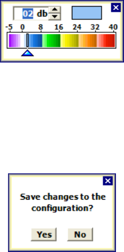
72
5. If you wish to edit a subset of thresholds, drag over the area of interest. For
selection of individual bins, you can use the Zoom In / Zoom Out button.
Once the desired bins are selected you can then click on Adjust Bins.
6. If you wish to reset only selected bins to defaults, click on the Reset Bins
button.
7. After you click on Adjust Bins or Adjust All, the Sensitivity Slider popup (see
Figure 6.11) will appear. Click on the sensitivity up/down bumpers to
change the sensitivity (in decibels). Negative values will lower the rejection
threshold in order to increase sensitivity. Positive values will increase the
rejection threshold in order to decrease sensitivity.
Figure 6.11 – Sensitivity Slider Popup
Save Desired Changes to the Sensor
After the configuration is complete, click the Save Config button to save the
changes to the sensor. If you attempt to leave the Lanes & Stop Bar view before
saving your changes you will be presented with the following prompt (see Figure
6.12).
Figure 6.12 – Save Changes Dialog
Zones and Channels
After the Lanes and Stop Bar configuration is saved, click on the Step 2 tab to bring
up the Zones & Channels view. This view allows you to place zones and configure
detection channels (see Figure 6.3). Each SmartSensor Matrix unit supports up to
eight zones and four channels. If unused, the eight zones are placed outside the
sensor view and labeled Z1 through Z8.
Detection zones are automatically placed in each lane near the stop bar. By
default, the zones are 30 feet in length. Each automatically placed zone is then
mapped to a detection channel.
To make changes to the zones and channels use the menu bar (see Figure 6.14).
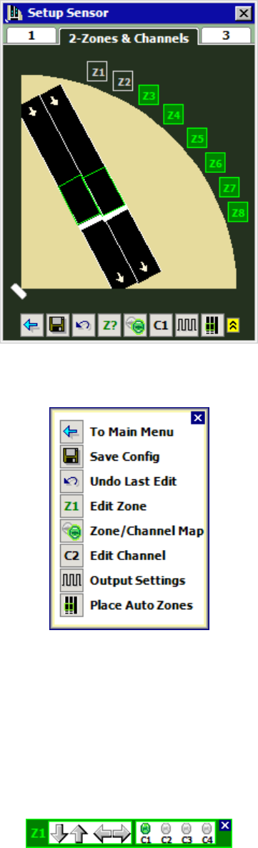
73
Figure 6.13 – Setup Zones & Channels View
Figure 6.14 – Setup Zones & Channels Menu Bar
The Edit Zone button will allow you to move a zone, and also specify the channels to
which it is mapped. Use the arrows to move the zone. To move just one corner of a
zone, select the zone by clicking on it, and the click again on the desired node. Then
drag the zone to the desired location. Zones are allowed to overlap each other.
Click on the C1 through C4 LEDs to map the selected zone to the desired channels.
If the LED is green the zone will be mapped to that channel. If it is gray then it will
not be mapped.
Figure 6.15 – Edit Zone Button
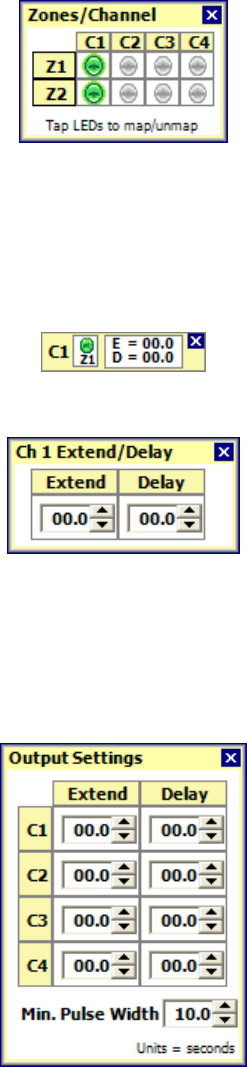
74
The Zone/Channel Map will also allow you to map or un-map zones to channels (see
Figure 6.16). A zone is mapped to a channel if the corresponding LED is green.
Otherwise it is not mapped.
Figure 6.16 - Zone/Channel Map Popup
The Edit Channel popup will also allow you to map / un-map channels. Click on the
LEDs to configure the mapping. This popup also allows you to view and then edit
extend and delay settings for the selected channel (see Figure 6.17). To edit the
extend and delay, click in the white box with the E and D, and the corresponding edit
boxes will appear (see Figure 6.18).
Figure 6.17 – Edit Channel Popup
Figure 6.18 – Edit Extend Delay
The extend and delay settings can also be specified using the Output Settings popup
(Figure 6.19). This popup also allows you to specify the minimum pulse width. The
minimum pulse width is the minimum duration a presence detection will be
signaled via the contact closure rack cards. All these output settings are specified
in seconds.
Figure 6.19 – Output Settings Popup
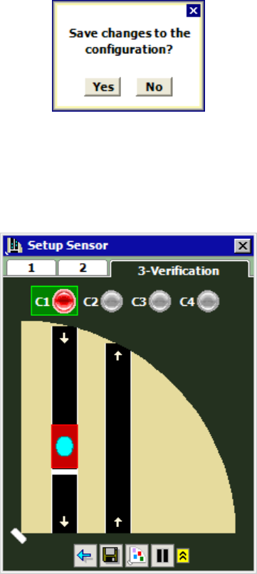
75
Press the Place Auto Zones button if you would like to manually invoke this
automatic feature. Please not that this will move any zone adjustments that you
may have made before saving.
After the configuration is complete, click the Save Config button to save the
changes to the sensor. If you attempt to leave the Zones & Channels view before
saving your changes you will be presented with the following prompt (see Figure
6.20).
Figure 6.20 – Save Changes Dialog
Verification
After the configuration is complete, you will want to verify vehicle detections. To do
so click on the Step 3 tab. This will bring up the Verification View (see Figure 6.21).
Figure 6.21 – Verification View
In the Verification View, vehicle detections will appear as light blue objects. The
extent of these detections will vary based upon the length of the detected vehicle
and the length of queued traffic.
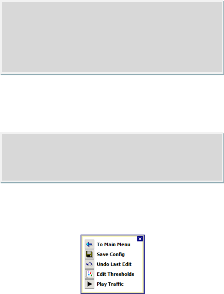
76
When detections are within a zone, they will cause the LEDs for the channels
mapped to that zone to activate. Active channels will appear red, and inactive
channels will appear gray (blank).
To see detections active the zones mapped to a particular channel, select that
channel by clicking on its LED. Active zones for the selected channel will appear
red, and inactive channels for the selected zone will appear black (blank).
As on the Edit Lanes & Stop Bar screen, you can use the menu bar to: save a
configuration, undo your last edit, edit thresholds, and pause/play traffic (see Figure
6.22).
Figure 6.22 – Verification View Menu Bar
Note
Only the zones for the selected channel will appear. If zones are not mapped
to any channel, they will not be seen in the Verification View.
Note
Vehicle detections in a stopped queue are represented by a continuous light
blue bar. This representation ensures that a zone will activate when queued
vehicles stop before and after the zone, but not directly over it. In addition, if
the first queued vehicle stops behind the stop bar and but is within 30 feet, the
displayed queue will be extended to the stop bar. This ensures that a stop bar
zone will activate when a vehicle stops near it in the corresponding lane.
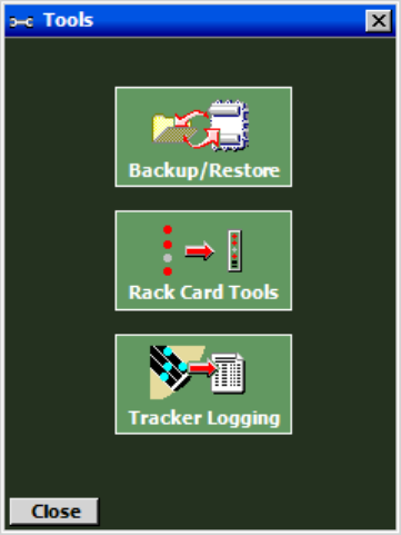
77
Tools
In this Chapter
Backup / Restore
Rack Card Tools
Tracker Logging
The Tools Screen allows you to perform several functions (see Figure 7.1).
Figure 7.1 – Tools Screen
Backup / Restore
Access Backup/Restore by clicking the Backup/Restore button on the Tools screen
(see Figure 7.2)
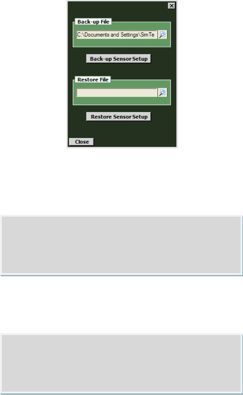
78
Figure 7.2 – Backup / Restore
The backup function allows you to backup the sensor settings you have changed. To
create a backup, click on the magnifying glass icon in the Back-up File section.
Choose a destination, type in a filename, and hit OK, then click the Back-up Sensor
Setup button.
The restore function allows you to restore a set of sensor settings you have backed
up. To restore, click on the magnifying glass icon in the Restore File section. Select
the backup file you wish to restore, hit OK, and then click the Restore Sensor Setup
button.
Warning
Restoring sensor settings will cause you to lose the settings previously on the
sensor, unless they are backed up.
Note
The backup will appear as an .ssc file. While this file can be opened as a text
file by using a program such as Notepad, do not edit the file, as it will change
the settings you backed up.
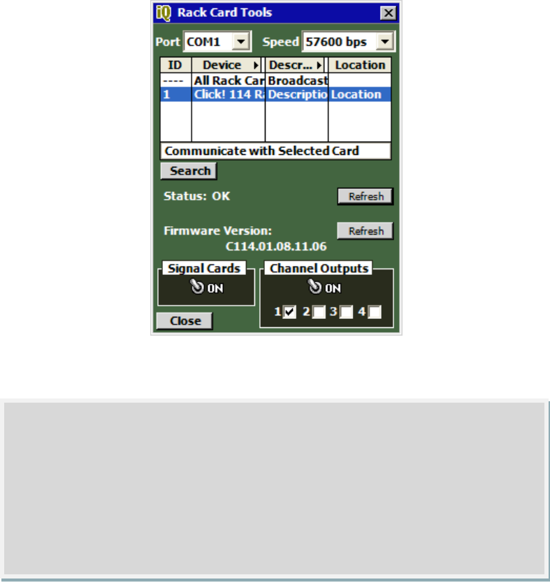
79
Rack Cards Tools
Access rack card tools by clicking the Rack Card Tools button on the Tools screen
(see Figure 7.3)
Figure 7.3 – Rack Card Tools
Serial data messages sent by the Rack Card Tool normally reach the rack cards via
T-bus and the patch cord connecting the Command and Control Bridge directly to
contact closure card shared multi-drop bus. The Rack Card Tool does not cause the
sensors to send contact closures to the rack cards.
Note
To reduce the amount of time spent onsite when installing a Wavetronix Stop
Bar Detection System, you can use the Rack Card Tool to setup the racks
cards, while cable is being pulled through conduit or the sensors are being
installed. This tool will allow you to verify that you have the correct channel
mapping into the traffic controller, even without the sensors installed. This tool
can also be used for troubleshooting.

80
To search for Click! 112/114 rack cards on the communication bus to which
SmartSensor Manager is connected:
1. Select the correct communications port using the Port drop down control.
2. Select the correct communications baud rate using the Speed drop down
control.
3. Click on the Search button.
4. Once a list of devices appears, click on the desired row. If you would like to
communicate to all the devices, select the first row, with the title “All Rack
Cards” in the device column. This selection will send broadcast messages to
all the connected rack cards. If you would like to communicate to an single
device, select the corresponding row. You can identify a device by its ID,
Device, Description, or Location fields.
When you are communicating with an individual device, the Status and Firmware
Version fields will be valid. The Status field indicates whether the rack card is
operating normally (OK) or whether it is in failsafe mode. If the device is in failsafe
mode, the text message may help you understand why the device is in failsafe. For
example if the text reads “Failsafe Initializing”, this indicates that the rack card has
never seen any detection call messages since it was rebooted. Or if the message
reads “Failsafe Timeout (No Data)”, this indicates that the rack card was previously
receiving detection calls, but has received any in the last 10 seconds or more.
The Firmware Version field lists the version of the rack card firmware. In the
example in Figure 7.3, the firmware is for a 114 card and was released on
11/06/2008. If you are communicating will all devices, the status and firmware
version fields are not applicable (N/A). When you would like to refresh the status of
these fields, click the associated Refresh button.
To help single-out devices you can use the Signal Cards toggle switch. When the
switch is ON, all selected devices will flash their main menu LEDs (see Figure 2.10).
If you have selected All Rack Cards, every card connected on the bus will flash the
main menu LEDs. If you have selected a single device, only the LEDs on this device
will flash.
The Channel Outputs toggle switch and 1-4 checkboxes are used to help assist in
testing of the rack card outputs. Boxes 3 and 4 will not appear if you are connected
to a two-channel rack card.
Note
When used with SmartSensor Matrix the rack cards should be configured to
communicate at 57,600 bps. If you are having communication issues, you
may want to verify that the rack cards are configured to communicate at
57,600 bps. See Appendix D to learn how to configure the rack cards.

81
If the Channel Outputs switch is ON, all the selected outputs on the Click! 112/114
rack card will be determined by the checkboxes (unless a sensor is actively pushing
data to the rack card over the detection call bus).
If there are not competing messages from another communication bus, an output
will be active when associated a box is checked. An active output will cause the
corresponding contact outputs on the card’s backplane to close and the detection
channel LED on the faceplate to activate (see Figure 2.10). If a box is not checked,
the output will be inactive. An inactive output will cause the corresponding contact
outputs on the card’s backplane to open and the detection channel LED on the
faceplate to deactivate.
When on the Channel Outputs toggle switch and 1-4 checkboxes can be very helpful
in verifying the I/O channel mapping from the rack card outputs to the traffic
controller inputs. By sequentially checking boxes 1-4 you should be able to quickly
verify the mapping of each channel, even in the absence of traffic.
Tracker Logging
Access the Tracker Logging tool by clicking on the Tracker Logging button on the
Tools screen (see Figure 7.4). This tool will allow you to log vehicle detections as
Note
If the Channel Outputs toggle switch is OFF, no channel output messages will
be sent to the Click! 112/114. However, this does not mean that the channel
outputs will be inactive. In fact, normally the cards will go into failsafe mode.
In failsafe mode, all detection channel outputs and their corresponding LEDs
will be active.
Warning
It is recommended that you disable pushing by sensors, or disconnect the
detection call bus patch cord for each sensor before using this tool. Otherwise,
the rack card may be receiving conflicting calls on its other bus.
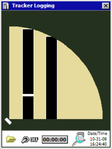
82
they are tracked through the sensors view. (This tool does not log vehicle tracks
seen on the Lanes & Stop Bars view of the Sensor Setup screen. It only records
vehicle detections as shown on the Verification page.) Recorded vehicle detections
can be used later for playback using a virtual connection.
Figure 7.4 Tracker Logging Tool
Click on the Log File icon to select a log file. The Select Tracker Log File screen
allows the user to specify the name of an existing log file or to create a new file (see
Figure 7.5).
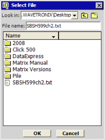
83
Figure 7.5 – Select Detection Log File Screen
Click the ON/OFF toggle switch icon to the “ON” position to begin logging vehicle
detections. Once activated, the duration of the logging session is displayed on the
“Elapsed:” timer display. Click the toggle switch to the “OFF” position to end a
logging session.
The vehicle detection log file is an ASCII text file and can be viewed using a
standard text editor. Click on the View Log icon to view the current log file using the
system’s default text editor (see Figure 7. 6).
Figure 7.6 – Log File

84
Appendix
In this Appendix
A – SmartSensor Matrix (SS225) Specifications
B – Matrix Cable Connector Assembly Instructions
C – Cable Lengths
D – Click! 112/114 Reference Guide
Appendix A – SmartSensor Matrix (SS225) Specifications
Parameters
Specifications
Operating Frequency: 24.125 GHz (K-band)
Detection Zones:
Up to 8 zones
Detection Channels:
Up to 4 channels
Detection Range:
6 to 100 ft (1.83 m to 30.48 m)
Detection View:
90 degrees
Elevation Angle:
65 degrees
Measured Quantities:
Vehicle presence
Communications:
Two RS-485 half-duplex connections
Power:
10.0 watts @ 9-28 VDC
Physical Dimensions:
13.2 in x 10.6 in x 3.3 in (33.5 cm x 27 cm x 8.3 cm)
Zone Resolution:
1 foot (0.3 m)
Ambient Operating Temp:
-40 C to 70 C
Humidity:
Up to 95% RH
Shock:
10 g 10 ms half sine wave
Transmitted Power at 3m:
<100 dBUv/m @24.125 GHz
Appendix B – Matrix Cable Connector Assembly Information
The connector end of the SmartSensor Matrix cable mates to the eight socket
connector on the sensor as shown in Figure B.1. Socket A is near the connector’s
key. Figure B.2 details the pinout of the cable connector and the corresponding wire
in the cable. The SmartSensor Matrix cable has 7 wires. Internal to the sensor
another pair of wires connect to the protective earth lug.
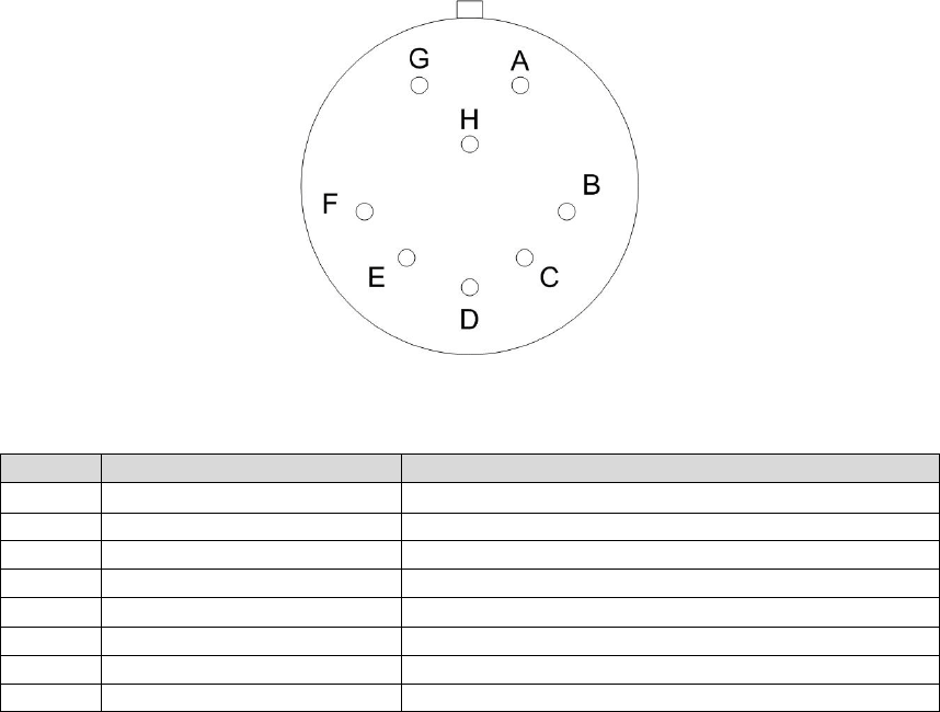
85
Figure B.1 – SmartSensor Matrix Connector (Plug End with Sockets)
Pin
Cable Wire
Signal Description
A Red DC+
B
White with orange stripe
Detection Call 485+ (Sensor Port 2)
C
Orange
Detection Call 485- (Sensor Port 2)
D
Drain / Shield
Drain
E
White with blue stripe
Command and Control 485+ (Sensor Port 1)
F
Blue
Command and Control 485- (Sensor Port 1)
G
Black
Common (Ground)
H
----
Reserved
Figure B.2 – Pinout for Power and Communication Signals
To create custom cables proper connector crimping tools are necessary. The
SmartSensor Matrix cable connector uses a MILC-C-26482 Series 1 connector,
crimping contacts, and a watertight back shell. A kit with these parts can be
ordered directly from Wavetronix.
Size 20 contacts are used to accommodate the 20 and 22 gauge wires in the
cable. (The SmartSensor cable’s red and black wires provide a 20 AWG wire pair.
The other pairs on the SmartSensor cable are 22 AWG and are normally used for
communication.)
To create a custom cable (see Figure B.3):
1. Slide the strain relief, follower, grommet, and back shell over the cable.
2. Strip the cable jacket and shielding back about 1.5 inches.
3. Strip each of the 7 SmartSensor cable wires back about 0.25 inches.
4. Insert the wires into the contacts and verify the wire is visible through the
contact inspection hole.
5. Crimp the wires by following the crimping tool instructions. Daniels
Manufacturing Company provides professional grade crimping tools and
detailed instructions on crimping. Wavetronix recommends the DMF AF8
M22520/1-01 or equivalent tool for crimping.
6. Manually press the contacts into the backside of the connector plug using
the pinout information in Figure B.2.
7. Use a DMC DAK20 or equivalent insertion tool to fully seat the contact into
the connector plug. Check the mating face of the connector to ensure that
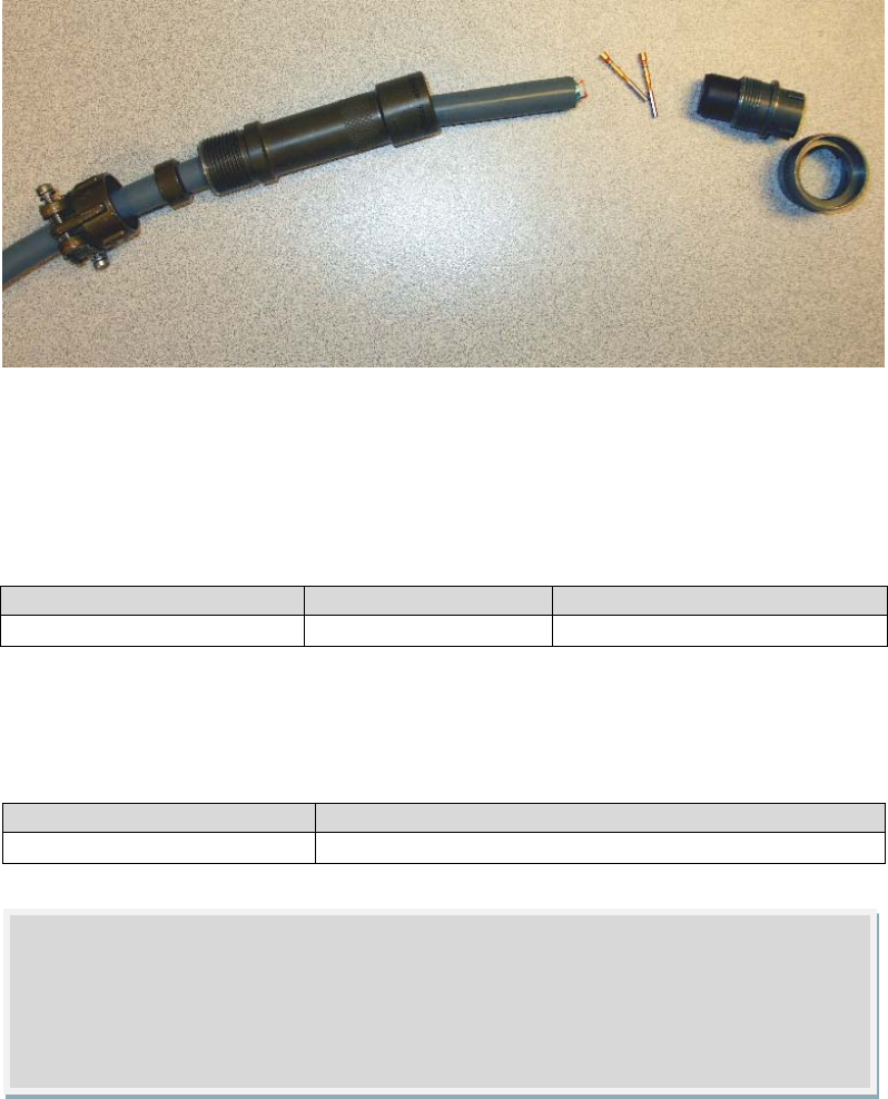
86
all the contacts are fully inserted. (A DMC DRK20 extractions tool or
equivalent is necessary to remove a misplaced or misaligned contact.)
8. Thread the back shell onto the connector plug. To keep the connector from
rotating during the threading process, connect the plug and coupling ring to
a sensor connector receptacle.)
9. Press all of the connector parts together. Thread the strain relief on to the
back shell.
10. Tighten the strain relief screws on the back
Figure B.3 – Connector sub-assembly parts
Appendix C – SmartSensor Matrix Cable Lengths
It is recommended that the sensor be powered off of 24 volts to achieve reliable
operation up to 500 feet away. Figure C.1 lists maximum cable lengths for 12 and
24 volts.
Power Wire Gauge
24 Volts
12 Volts
20 AWG 500 ft 100 ft
Figure C.1 – Maximum Cable Length for Power (ft)
For communications, both of the sensor’s RS-485 communication ports operate at
57.6 Kbps to achieved reliable communications up to 500 feet away (see Figure
C.2).
Baud Rate
RS-485
57.6 Kbps 500 ft
Figure C.2 – Maximum Cable Length for Wired Communications (ft)
Note
If you have a need for a cabled connection over 500 feet, contact Wavetronix
technical services for assistance.
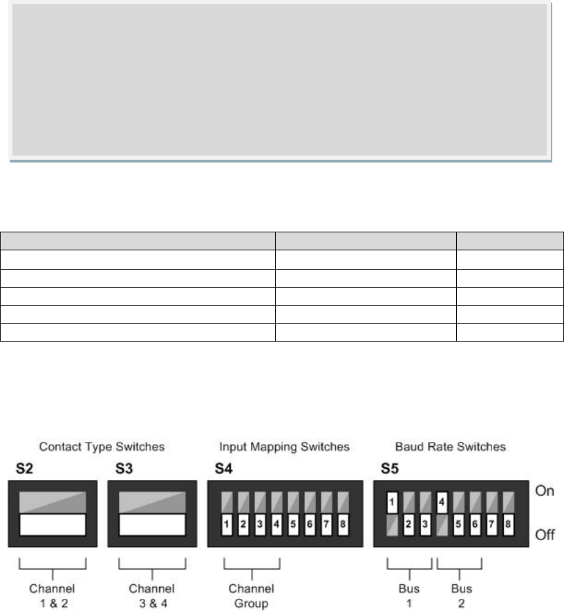
87
Appendix D – Click! 112/114 User Reference Guide
The Click! 112 and 114 are 2-channel and 4-channel contact output rack cards.
Each contact output is electrically isolated and are normally open. When the cards
receive the appropriate serial messages from SmartSensors, they will close the
contact outputs. The contact closure is used to pull-down the 24VDC reference
provided by standard traffic controllers and traffic cabinet bus interface units. This
type of digital I/O is standard in NEMA TS1, NEMA TS2, 170, 2070, and ATC traffic
cabinet systems.
When used with SmartSensor Matrix the rack cards usually receive broadcast
detection call messages. However, the rack card protocol also supports individual
addressing. Individual addressing is used by the rack card tools in SSMMX.
The rack cards are software and hardware configurable. Hardware configuration is
performed using switches on the side of the card (see Figure D.1).
Switch Name
Description
Card Labels
Mode Switch
Push button on faceplate
S1
Contact Type Switch Channel 1 & 2
1-switch DIP switch
S2
Contact Type Switch Channel 3 & 4
1-switch DIP switch
S3
Channel Group / Input Mapping Switch
8-switch DIP switch
S4
Baud Rate Switch
8-switch DIP switch
S5
Figure D.1 – Hardware Configuration Switches
Figure D.2 illustrates the 4 possible DIP switch modules on the side of the card. To
turn a switch on, push it up. To turn a switch off, push it down. In this example, only
switches 1 and 4 of S5 are on.
Figure D.2 – DIP Switches on the side of the card
Note
On power up, the rack cards will go into failsafe mode if they are not receiving
detection call messages from SmartSensor Matrix. So even though the
contact outputs are normally open, they will be closed when an active
connection from SmartSensor Matrix (or other source device) does not exist.
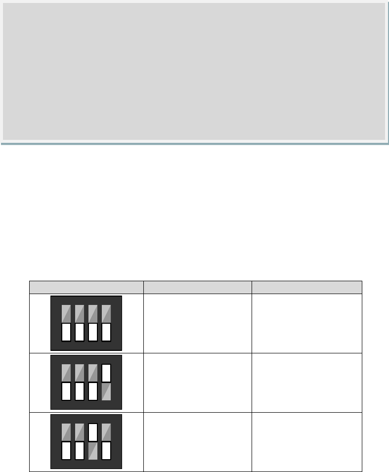
88
When S2 is switched off it will provide a contact outputs (dry outputs) for channels 1
and 2. When S2 is switched on it will provide voltage outputs (wet outputs) for
channels 1 and 2. S3 has the same functionality, but for channels 3 and 4. S2 and
S3 are normally both on or both off.
The first four input mapping switches (1-4) for S4 are used to select a channel
group. A channel group indicates which input channels are mapped to the cards
output channels. If the first four input mapping switches are all off then the channel
group is software configurable. Otherwise, the pattern of these switches selects the
channel group (see Figure D.3). The same on/off pattern used for these dip
switches is also used when doing software selection of the channel groups using the
faceplate mode switch (Compare Figure D.3 to Figure D.6). This allows selection of
channels as high as channel 28. Contact Wavetronix technical support if you have
questions on how to select channel groups.
S4 DIP Switch Pattern
Click! 114
Click! 112
1234
Software configured Software configured
123
4
Channels 1-4 Channels 1-2
1 2
3
4
Channels 5-8 Channels 3-4
Figure D.3 – Channel Group Selection Using Input Mapping Switches (1-4)
The first three baud rate switches (1-3) for S5 are used to select the baud rate for
Bus 1. If the first three baud rate switches are all off then the Bus 1 baud rate is
software configurable. Otherwise, the pattern of these switches selects the Bus 1
baud rate.
Note
A switch is also off if it is not loaded onto the card. For example, S2 and S3
are not typically loaded because the rack card normally provides contact
outputs. These switches are only present in cases where the rack card needs
to output a voltage (wet) instead of a contact (dry). Please contact Wavetronix
customer support, if you have an application that requires a voltage output.
The voltage will normally be near VCC (typically 12 or 24 V). Then when the
contact closes, the output voltage will be near 0 V.
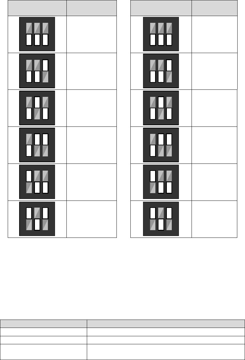
89
Likewise, the next three baud rate switches (4-6) for S5 are used to select the baud
rate for Bus 2. If these baud rate switches are all off then the Bus 2 baud rate is
software configurable. Otherwise, the pattern of these switches selects the Bus 2
baud rate.
S5 DIP
Switch Pattern
Bus 1
Baud Rate
S5 DIP
Switch Pattern
Bus 2
Baud Rate
123
Software
configured
456
Software
configured
1 2
3
9600 bps
4 5
6
9600 bps
1
2
3
19200 bps
4
5
6
19200 bps
1
2 3
38400 bps
4
5 6
38400 bps
1
2 3
57600 bps
4
5 6
57600 bps
1
2
3
115200 bps
4
5
6
115200 bps
Figure D.4 – Baud Rate Selection using Baud Rate Switches
There are two methods of software-driven configuration: mode switch (on the card’s
front panel) and Click! Supervisor software.
Figure D.1 lists the modes that can be selected using the front panel mode switch.
To select a mode hold down the mode switch button, until the corresponding LED
activates. Release the button and then momentarily press it once again in order to
select the mode.
Menu Mode LEDs
Description
Red Normal operation
Blue Flashing
Select input channel group
Green Automatically configure baud rates to a compatible
device

90
Yellow
Manually configure BUS1 baud rate
Yellow Flashing
Manually configure BUS2 baud rate
Red Flashing
Reset configuration to factory defaults
None
Cancel and exit menu
Figure D.5 Front-panel software configuration modes
The Blue Flashing mode is used to select the input channels to map to the output
channels. This mode will display the input channel group, but not allow it to be
software configured unless the S4 DIP switch makes the channel group selection
software configurable. Figure D.2 shows them submenu LED patterns that
correspond to specific channel selections. While in the Blue Flashing Mode hold the
mode switch until the desired submenu LED pattern is displayed. Release the
button and then momentarily press it once again in order to finalize selection of the
input mapping. After selection of the channel group, the card will return to the
normal operating mode.
Submenu LED
Pattern
Click! 114
Click! 112
○○○●
Channels 1-4 Channels 1-2
○○●○
Channels 5-8 Channels 3-4
○○●●
Channels 9-12 Channels 5-6
○●○○
Channels 13-16 Channels 7-8
○●○●
Channels 17-20 Channels 9-10
○●●○
Channels 21-24 Channels 11-12
○●●●
Channels 25-28 Channels 13-14
●○○○
NA Channels 15-16
●○○●
NA Channels 17-18
●○●○
NA Channels 19-20
●○●●
NA Channels 21-22
●●○○
NA Channels 23-24
●●○●
NA Channels 25-26
●●●○
NA Channels 27-28
○○○○ Cancel menu and
exit
Cancel menu and
exit
Figure D.6- Blue Flashing Mode Submenu
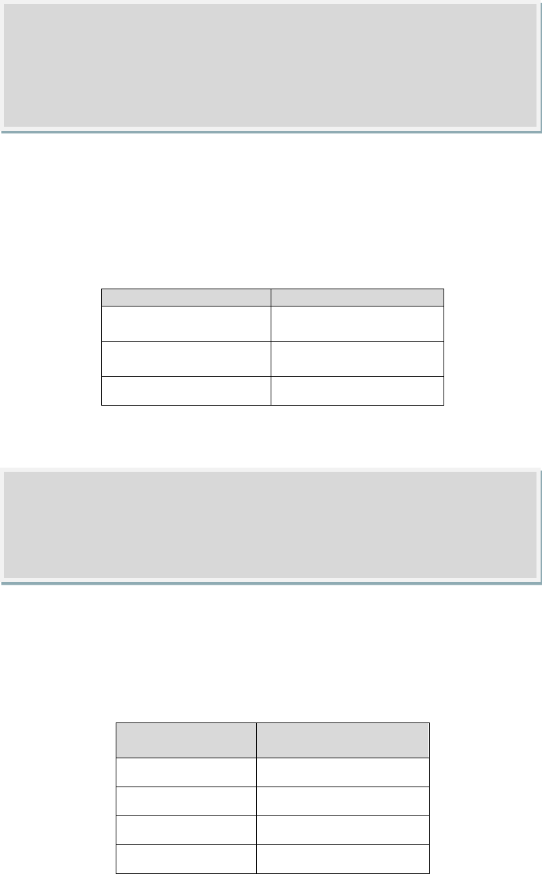
91
The Green mode is used to automatically detect the baud rate for both BUS1 and
BUS2. This mode will not be present unless the S5 DIP switch makes the baud rate
selection software configurable. Figure D.3 shows them submenu LED patterns that
correspond to specific auto-baud actions. While in the Green mode hold the mode
switch until the desired submenu LED pattern is displayed. Release the button and
then momentarily press it once again in order to execute the desired action.
Submenu LED Pattern
Action
○○○● Auto-configure baud
rate of BUS 1
○○●○
Auto-configure baud
rate of BUS 2
○○○○
Cancel menu and exit
Figure D.7 – Green Flashing Mode Submenu
During auto-discovery the submenu LEDS will sequence. Then, when the baud rate
is detected the submenu LEDS will momentarily display an on/off pattern that
indicates the detected baud rate (see Figure D.8). If the baud rate could not be
detected, all four submenu LEDs will activate. After display of the detected baud
rate the card will return to the normal operating mode.
Submenu LED
Pattern
Baud Rate
○○○●
9600 bps
○○●○
19200 bps
○○●●
38400 bps
○●○○
57600 bps
Note
You only have access to the auto baud menu when one or both ports are
software configurable.
Note
The LED pattern of all blanks will cancel the menu and exit. Any inactivity of
about 1 minute will automatically exit the menu making no selection, and
return to normal operation.
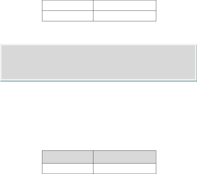
92
○●○●
115200 bps
●●●●
Error
Figure D.8 – Baud Rate Encoding
The Yellow and Yellow Flashing modes are used to manually software-select the
baud rate for Bus 1 and Bus 2 respectively. Figure D.3 shows them submenu LED
patterns that correspond to specific auto-baud actions. While in either mode hold
the mode switch until the desired submenu LED pattern is displayed (see Figure
D.8). Release the button and then momentarily press it once again in order to
execute the desired action. If you wish to cancel and exit the menu without having
made a selection wait until the submenu LEDs are all blank (see Figure D.9).
Submenu LED
Pattern
Action
○○○○
Cancel menu and exit
Figure D.9 –LED Submenu Pattern to Cancel Menu and Exit
The Red Flashing mode is used to reset the sensor to software factory defaults.
Please note that the position of the DIP switches may override software factory
defaults.
The Click! Supervisor software runs on PC and Pocket PC platforms. To learn how to
install the Click! Supervisor software, contact Wavetronix Technical Services or
consult the Click! user documentation. To help you select an individual rack card on
a multi-drop bus, Supervisor will auto-discover the device ID, model number and
description. You may wish to enter into the description field information pertaining
to rack slot position and detected traffic direction. For example, you can enter “NB
traffic slot 2”. Select the rack card you want to configure from the list (see Figure
D.10) and then select the driver you wish to use to configure the card from the list of
available drivers.
Once you connect to the rack card, Supervisor will recommend to upgrade the
embedded software if a newer version is available. The code files for an upgrade
should be installed in the “Click Home\Drivers\112” and “Click Home\Drivers\114”
directories. Contact Wavetronix customer service if you have questions regarding
the code or driver files in these directories. The last three pairs of numbers in the
filename (before the .txt suffix) indicate the release date of the code: YY.MM.DD
(year.month.day).
Note
When the DIP switches control the baud rates, you the specified baud rate is
displayed in the menu, but cannot be changed.
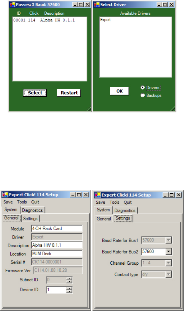
93
Figure D.10 – Supervisor Connection and Driver Selection
Figure D.11 illustrates the settings that are configurable using the Expert driver. As
explained earlier, some settings are only software configurable if the hardware
switches are set appropriately. For example, the baud rates for bus 1 and bus 2 are
software configurable based upon the configuration of the baud rate switches on
the side of the board (S5). If the hardware switches prevent software configuration
for a specific setting, the user control will display the current setting, but will be
disabled and read-only.
Figure D.11 – Software Configuration
To setup or view the individual address of a rack card click on the Device ID control
(see Figure D.11).
The pin out of the Click! 112/114 backplane contacts is shown in Figure D.13.
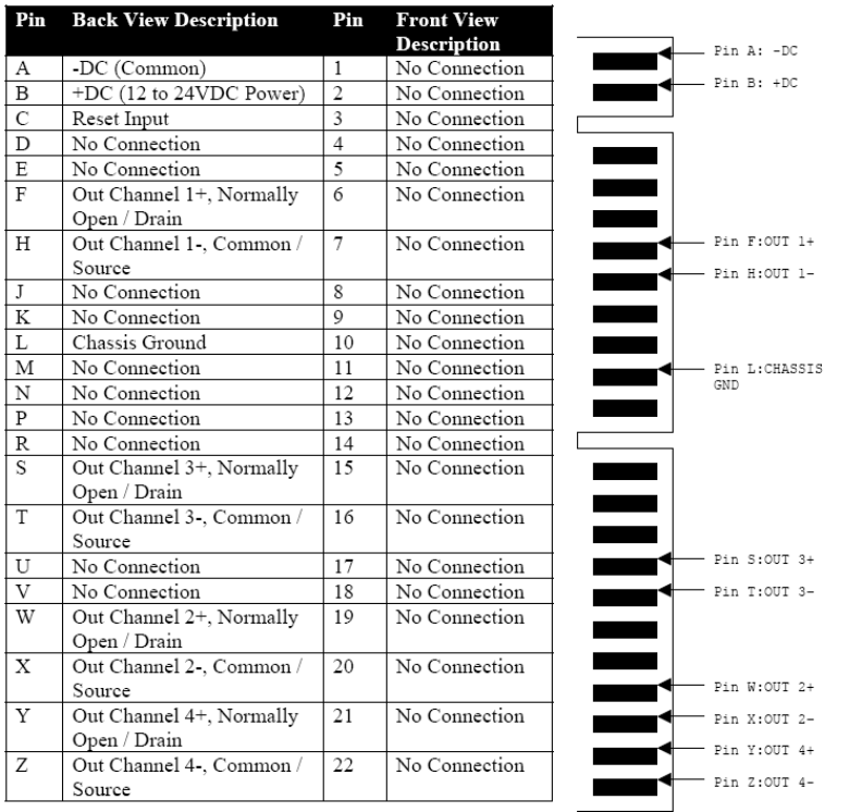
94
Figure D.12 – Rack Card Pin Out
Appendix E – Click! 221 User Reference Guide
The Click! 221 is a DC 8-Amp surge protection device (8 amps is the maximum
rating of a T-bus connector). The DC source voltage and PE (protective earth) should
be wired into the screw terminals on the bottom side of the device. A protective
earth wire of 12 AWG is recommended. The device works with up to 8 amps of
continuous current at a maximum of 28 VDC.
DC-voltage outgoing onto the T-bus is protected from electrical surges incoming
from the DC+ and DC- screw terminals. These terminals do not have reverse-
polarity protection, but assumes that all downstream devices will have proper
polarity protection. The surge protection meets the IEC 61000-4-S 4KV (Class 4)
specification.
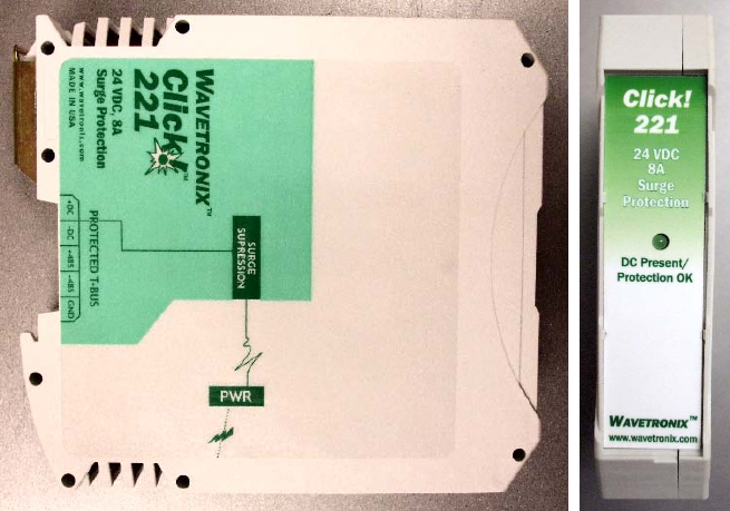
95
The LED on the faceplate will be on if the device is properly powered and the surge
protection is operational. If the DC wires are wired backwards (reverse polarity),
the device is not powered, or the surge protection circuitry is no longer operational
the LED will be off. If the LED flickers on an then off when power is applied, this
means that the device is conducting power but that the surge is no longer fully
functional. When the surge is no longer fully functional, please contact Wavetronix
Technical Services for assistance.