Wayne Dalton 0001142 Z-WAVE PRODRIVE User Manual USERS MANUAL
Wayne Dalton Corporation Z-WAVE PRODRIVE USERS MANUAL
USERS MANUAL

5015 B.U. Bowman Drive Buford, GA 30518 USA Voice: 770-831-8048 Fax: 770-831-8598
FCC Part 15.249
Transmitter Certification
Test Report
FCC ID: KJ8-0001142
FCC Rule Part: 15.249
ACS Report Number: 07-0047 - 15C
Manufacturer: Wayne-Dalton Corporation
Model(s): 3220C-Z, 3222C-Z, 3224C-Z,
3320B-Z, 3322B-Z, 3324B-Z, 3221C-Z
User’s Manual
INSTALLATION INSTRUCTIONS AND OWNER’S MANUAL
Chain/ Belt Drive
Models: 3220C, 3221C, 3222C, 3224C, 3320B, 3322B, 3324B
3220C-Z, 3221C-Z, 3222C-Z, 3224C-Z, 3320B-Z, 3322B-Z, 3324B-Z
IMPORTANT NOTICE!
Read the enclosed instructions carefully before installing/operating
this garage door opener. Pay close attention to all warnings and
notes. This manual MUST be attached to the wall in close proximity
to the garage door.
© Copyright 2006 Wayne-Dalton Corp. Part No. 325809 Rev.1 12/01/2006
FOR RESIDENTIAL SECTIONAL OVERHEAD GARAGE DOORS ONLY!
DO NOT USE ON ONE PIECE DOORS!
IMPORTANT! THE DOOR AND OPENER WILL NOT FUNCTION PROPERLY UNTIL
INFRARED SAFETY SENSORS ARE INSTALLED AND PROPERLY ADJUSTED!
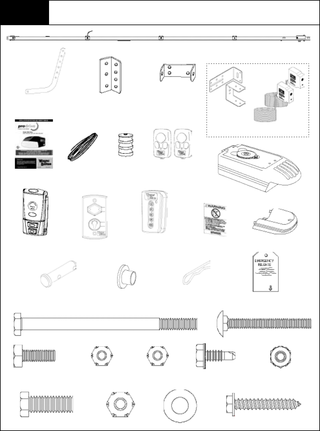
Keychain/Visor
Transmitter (1 or 2)
Entrapment Label Light Diffuser
Opener
Emergency Release Tag
Bell Wire Red Emergency
Release Knob
Wall Mounting
Brackets
Door Arm
Lower
Door Bracket
Rail Assembly W/Upper
Door Arm
NOTE: Depending on the opener model, some parts
listed may not be supplied.
Package Contents
Multifunction
Wall Station
W/Hardware
Wired Deluxe Wall
Station W/Hardware
5 Button Wireless
Keyless Entry W/
Hardware
1/4” x 4” Hex Head Bolt
(2) 1/4”-20 x 3/4” Machine Bolts (2) 1/4” Nylock Nuts
3/8”-16 x 1” Machine Bolt 3/8” Plastic Insert
Locking Nut
(2) 1/4” - 20 x 2” Carriage Bolts
1/4” Plastic Insert
Locking Nut (2) 1/4” - 20 x 5/8”
Self Drilling Screws
(2) 1/4” x 1-1/2” Lag Screws
3/8” Flat Washer
Infrared Safety Sensors
(1 Sender + 1 Receiver)
(2) Safety Sensor
Brackets
Wired Safety Sensors W/ Hardware
(2)1/4” Locking Nuts
Please Do Not Return This Product To The Store. Call Us Directly! Our Trained Technicians Will Answer Your Questions and/or Ship Any Parts You May Need
You can reach us Toll Free at 1-888-827-3667 for Consumer Assistance or online at www.wayne-dalton.com
I
Owner’s Manual
Nylon Shoulder Bushing5/16” x 1-1/4” Multi Grip
Clevis Pin
Hairpin Cotter

PRE-INSTALLATION INSPECTION OF YOUR GARAGE DOOR
PRIOR TO PRODRIvE™ OPENER INSTALLATION
To ensure your new Prodrive™ opener works as intended, your garage door must be properly
installed and balanced.
Before installing your garage door opener, open and close you door manually to ensure it
operates smoothly from top to bottom. A properly balanced door should not take a lot of
effort to open or close by hand. The door should stay in the open and in the closed
position without drifting down or creeping up. If a door opens fast, the door may need spring
tension reduced. If the door drops fast, the door may need spring tension increased.
If the door operates properly, then proceed to your Prodrive™ installation manual for
instructions on how to install the Prodrive™ garage door opener.
If the operation of the door does not meet these requirements, adjust the spring
balance per your door’s installation manual or call a professional installer to make
adjustments before installing Prodrive™.
Instruction manuals are available for download on www.wayne-dalton.com. Use the web site to
also nd the location of your nearest professional dealer.
Once the door is properly balanced and operates smoothly, you may proceed with the
installation of your Prodrive™ garage door opener.
Please Do Not Return This Product To The Store. Call Us Directly! Our Trained Technicians Will Answer Your Questions and/or Ship Any Parts You May Need
You can reach us Toll Free at 1-888-827-3667 for Consumer Assistance or online at www.wayne-dalton.com
II
Pre-Installation
IMPORTANT! Before starting the installation read these instructions thoroughly to
familiarize yourself with all aspects of installation and adjustment.
IMPORTANT: IF YOUR GARAGE HAS NO SERVICE ENTRANCE DOOR, INSTALL AN OPTIONAL OUTSIDE QUICK RELEASE LOCK. THIS ACCESSORY
ALLOWS MANUAL OPERATION OF GARAGE DOOR FROM OUTSIDE IN CASE OF POWER FAILURE.
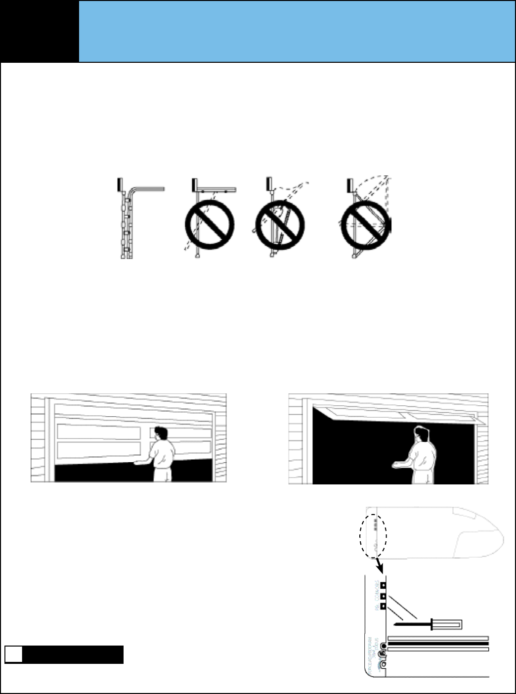
IDENTIFY YOUR DOOR
Identify your door by referring to illustrations below and verify that your door type is a sectional door with curved track. Do not install if the door
is any type of one piece door.
NOTE: The opener has been designed for sectional doors. Do not attempt to install this opener on any style one piece door. Using this opener on
a one-piece door may result in serious personal injury or property damage.
TEST YOUR DOOR
Before you begin, complete the following two tests to insure that the door is balanced and working properly. A door that binds, sticks or is out
of balance could cause severe injury. Do not attempt to compensate for an improperly adjusted door by the installation of an opener. This will
interfere with the proper operation of the opener’s safety features and/or may damage the door or opener. Have a qualified service person
make any needed adjustments or repairs before proceeding with installation.
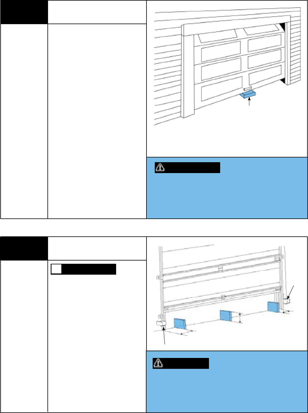
Door Test One
Raise and lower the door and check closely for any sticking or binding
that may occur. Lift the door approximately half way open, as
illustrated. When releasing the door, it should stay in position. If spring
tension pulls the door further open or door weight pulls it down, your
door is not properly adjusted.
Door Test Two
When properly installed, a door should remain clear of the
opening, when allowed to rest at its natural, full open position.
If “door drift” pulls door back into opening or spring tension is
not sufficient to pull door totally clear of opening, the door is not
properly adjusted.
PRE-ASSEMBLY CHECK
Every opener is factory tested and shipped with the limit switch adjustment in the door CLOSED
position. If the opener has been powered up before assembly, perform the following steps to insure
that the limit switch adjustment is in the door CLOSED position. Connect the opener to a power
source and short across the screw terminals labeled “PB” and “COM” with a metal screw driver.
Motor should start; run through a full OPEN cycle, (driven gear rotates clockwise) and stop. This
will leave opener in OPEN position. To get the opener back to full CLOSE position, short and hold
“PB” and “COM” terminals again (driven gear rotates counter clockwise). Continue to short
terminals until opener stops in the CLOSED position. If the contact between “PB” and “COM” is
lost, the motor will stop, reverse, and travel back to the open limit, repeat with a constant short
across “PB” and “COM”.
CAUTION: KEEP CLEAR OF ALL ROTATING AND MOVING PARTS.
FAILURE TO KEEP CLEAR OF ROTATING AND MOVING PARTS CAN RESULT IN SEVERE INJURY.
Disconnect from power source and proceed to assembly.
Right Side Of Opener
WARNING
Please Do Not Return This Product To The Store. Call Us Directly! Our Trained Technicians Will Answer Your Questions and/or Ship Any Parts You May Need
You can reach us Toll Free at 1-888-827-3667 for Consumer Assistance or online at www.wayne-dalton.com
III
1. Open and Close Cycle Control:
Allows garage door to be started and stopped by push button,
transmitter or wall station. The next impulse sends a stopped garage
door in opposite direction.
2. Emergency Disconnect:
Manual disconnect permitting operation of door during power failure
with automatic reconnect when opener is reactivated. See page 27.
3. Opener light:
Automatically turns on when opener is activated and remains on for
four minutes for convenience and safety.
4. Mechanical Door Lock:
When properly adjusted, opener locks door in closed position
preventing unwanted entry. See Adjustment # 3 on page 32.
5. Obstruction Warning Light:
The convenience light will flash after sensing an obstruction in the
down direction and/or if the safety system malfunctions while in the
open position.
6. Motor:
Permanently lubricated, thermally protected, heavy duty motor with
automatic reset.
System Features
7. Safety System:
Independent up and down force adjustments. When properly adjusted,
the safety system will automatically reverse when obstructed in down
direction and return to fully open position. The door will stop when
obstructed in the up direction. See Adjustment #2 on page 32.
8. Infrared Safety Sensors:
Wired infrared reversing sensors detect an obstruction in door path and
react by reversing door.
9. Multi-Function Wall Station:
Wired wall station provides up/down door motion control and
independent overhead light on/off control. Wireless multi-function wall
station provides up/down door motion control, independent overhead
light on/off control, door down delay, adjustable “pet position” function,
and “pet position” program button.
10. Homelink® Compatibility:
Opener is capable of “learning” automobile equipped Homelink®
transceivers. Visit: www.homelink.com.
11. Rolling Code Technology:
Wireless transmitters, multi-function wall stations and wireless keyless
entry use rolling code which prevent would be thieves from “grabbing”
the transmitter’s digital code.
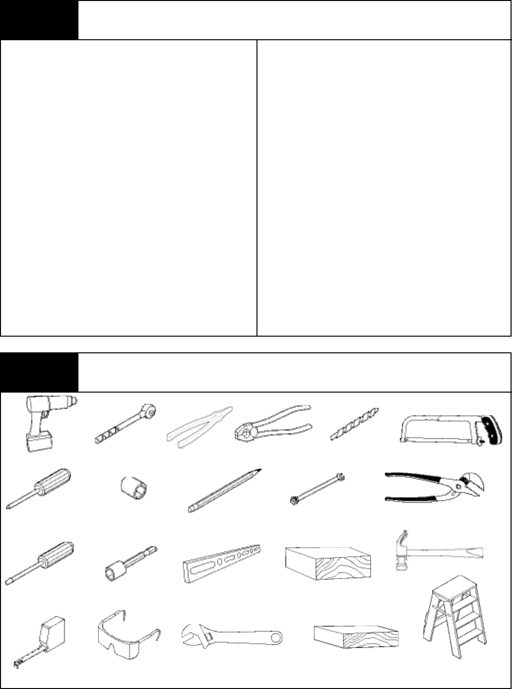
Tools Needed
Safety Glasses
Phillips Head
Screwdriver
Non-Metallic
Step Ladder
Ratchet Wrench
7/16” Wrench
5/64”, 3/32”, 1/8”, 3/16”
Drill Bits
1/4”, 3/8”, 7/16”,
1/2”, 9/16” Sockets
Flat Tip
Screwdriver
Level7/16” Socket Driver
Pliers/Wire Cutters
Tape Measure
Pencil
Power Drill
Adjustable Wrench
Hacksaw
Pliers
2 x 6 x 12 Solid Test
Object
2 x 4 Board
Needle Nose Pliers
Hammer
Please Do Not Return This Product To The Store. Call Us Directly! Our Trained Technicians Will Answer Your Questions and/or Ship Any Parts You May Need
You can reach us Toll Free at 1-888-827-3667 for Consumer Assistance or online at www.wayne-dalton.com
IV

Table of Contents
Package Contents ..............................................................................I.
Pre-Installation Inspection .............................................................II, III
Tools Needed ...................................................................................IV.
Important Safety Instructions ............................................................V.
Prodrive™ Installation ..................................................................1-5.
Pre-Operation .............................................................................6-19.
Optional Installations ................................................................20-26.
Operation .................................................................................27-32.
Programing Wireless Wall Station(s) Or Transmitter(s) to Opener ... 33.
Maintenance .................................................................................. 34.
Troubleshooting ............................................................................. 35.
Parts Breakdown Rail Assembly ..................................................... 36.
Parts Breakdown Opener Assembly ............................................... 37.
Accessories .................................................................................... 38.
Templates ...................................................................................... 39.
Customer Service Number ............................................................. 40.
Warranty ........................................................................................ 41.
Definition of key words used in this manual:
INDICATES A POTENTIALLY HAZARDOUS SITUATION WHICH,
IF NOT AVOIDED, COULD RESULT IN SEVERE OR FATAL
INJURY.
CAUTION: PROPERTY DAMAGE OR INJURY CAN RESULT FROM
FAILURE TO FOLLOW INSTRUCTIONS.
IMPORTANT: REQUIRED STEP FOR SAFE AND PROPER OPENER
OPERATION.
NOTE: Information assuring proper installation of the opener.
WARNING
WARNING
INCORRECT INSTALLATION CAN
LEAD TO SEVERE OR FATAL
INJURY. FOLLOW THESE
INSTRUCTIONS CAREFULLY.
IMPORTANT INSTALLATION
INSTRUCTIONS
1. READ AND FOLLOW ALL INSTALLATION INSTRUCTIONS.
2. Do not connect the opener to electrical power until instructed to do so.
3. Install the entrapment warning label next to the wall station in a
prominent location. Install the emergency disconnect label on the
emergency disconnect cord.
4. Remove all ropes and remove, or make inoperative in the unlocked
position, all locks connected to the garage door before installing the
opener.
5. Do not wear rings, watches or loose clothing when installing or servicing
a garage door system.
6. It is important that you install all the components supplied with the
Prodrive™ opener, i.e., wall stations, safety sensors, etc. Use of parts not
supplied by Wayne-Dalton Corp. may cause the opener to malfunction
and create unsafe conditions.
7. Wear protective eye wear when installing or servicing the opener or door.
8. Install opener on a properly balanced and operating garage door. Have a
qualified service person make adjustments/repairs to cables, spring
assemblies, and other hardware before installing the opener. An
improperly balanced door could cause severe or fatal injury.
9. Where possible, install the opener seven feet or more above the floor.
Mount the emergency disconnect six feet above the floor.
10. Locate the wall station: (a) within sight of door, (b) at a minimum height
of five feet, so small children cannot reach it, and (c) away from all
moving parts of the door.
11. After installing the opener, the door must reverse when it contacts a
1-1/2” high object (or 2 x 4 board laid flat) on the floor.
12. Installation and wiring must comply with local building and electrical
codes. Connect the power cord to a properly grounded outlet. Do not
remove the ground pin from power cord.
13. To reduce the risk of injury to persons, use this opener only with
sectional overhead doors.
14. Top section of garage door may need to be reinforced before
attaching opener. Check with your garage door manufacturer for
their recommendations.
15. Do not use sensitivity adjustments to compensate for a poorly
operating door. This will prevent proper operation of the safety
reverse feature and may damage the door and cause possible
severe or fatal injury.
16. Open door must not close and closing door must reverse and open
if infrared safety sensors are obstructed by 6” high object placed on
garage floor.
17. Use a sturdy, non-metallic step ladder when installing opener.
AFTER INSTALLATION IS COMPLETE, FASTEN
THIS MANUAL NEAR GARAGE DOOR. PERFORM
OBSTRUCTION TESTS MONTHLY AND
MAINTENANCE AS RECOMMENDED. SEE PAGES
17 & 34.
Please Do Not Return This Product To The Store. Call Us Directly! Our Trained Technicians Will Answer Your Questions and/or Ship Any Parts You May Need
You can reach us Toll Free at 1-888-827-3667 for Consumer Assistance or online at www.wayne-dalton.com
V
Please Do Not Return This Product To The Store. Call Us Directly! Our Trained Technicians Will Answer Your Questions and/or Ship Any Parts You May Need
You can reach us Toll Free at 1-888-827-3667 for Consumer Assistance or online at www.wayne-dalton.com
1
1Attaching Opener to Rail
Tools Needed:
3/8” Socket
Ratchet Wrench
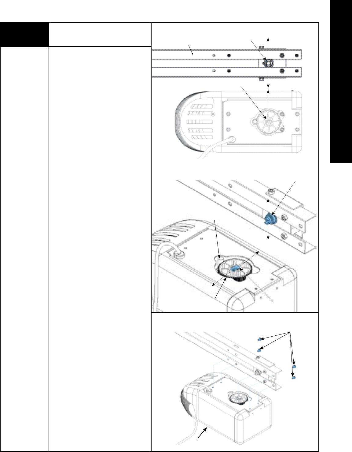
IMPORTANT: THE DRIVER GEAR IN THE
OPENER MUST BE PROPERLY ALIGNED
WITH THE SPROCKET/ COUPLING COGS IN
THE RAIL ASSEMBLY AND THE MOUNTING
BOLTS FULLY TIGHTENED, BEFORE
POWERING UP THE OPENER. NEGLECTING
TO DO THIS WILL RESULT IN GEAR FAILURE.
Before assembly, align sprocket/ coupling
cogs to match notches of driver gear. Rotate
the motor spline to position driver gear so
the nearest notch in driver gear is directly
behind motor spline, as illustrated.
NOTE: Do not rotate more than 1/2 turn.
Place opposite end of rail on temporary
support approximately 6” in height.
Proceed with attaching rail to opener,
ensuring proper engagement between
sprocket/coupling cogs and driver gear
notches. Realign if necessary, making sure
to keep any rotation only to the nearest
notch. Using the (4) pre-attached
1/4”-20 x 5/8” hex head bolts, assemble
rail to opener using 3/8” socket; tighten
securely.
NOTE: Do not plug the opener power cord
into electrical outlet until opener is fully
installed and you are instructed to do so in
this manual.
1/4” - 20 x 5/8”
Hex Head Bolts
Opener
INSTALLATION
Driver Gear
Sprocket / Coupling Cogs
Motor Spline
Notches
Notches
Sprocket / Coupling Cogs
Opener
Top View
Rail Bottom
(Facing Upwards)
Please Do Not Return This Product To The Store. Call Us Directly! Our Trained Technicians Will Answer Your Questions and/or Ship Any Parts You May Need
You can reach us Toll Free at 1-888-827-3667 for Consumer Assistance or online at www.wayne-dalton.com
2
2Positioning and Installing
Front Wall Bracket
NOTE: It is recommended that the door
opener be installed 7 feet or more above the
garage floor.
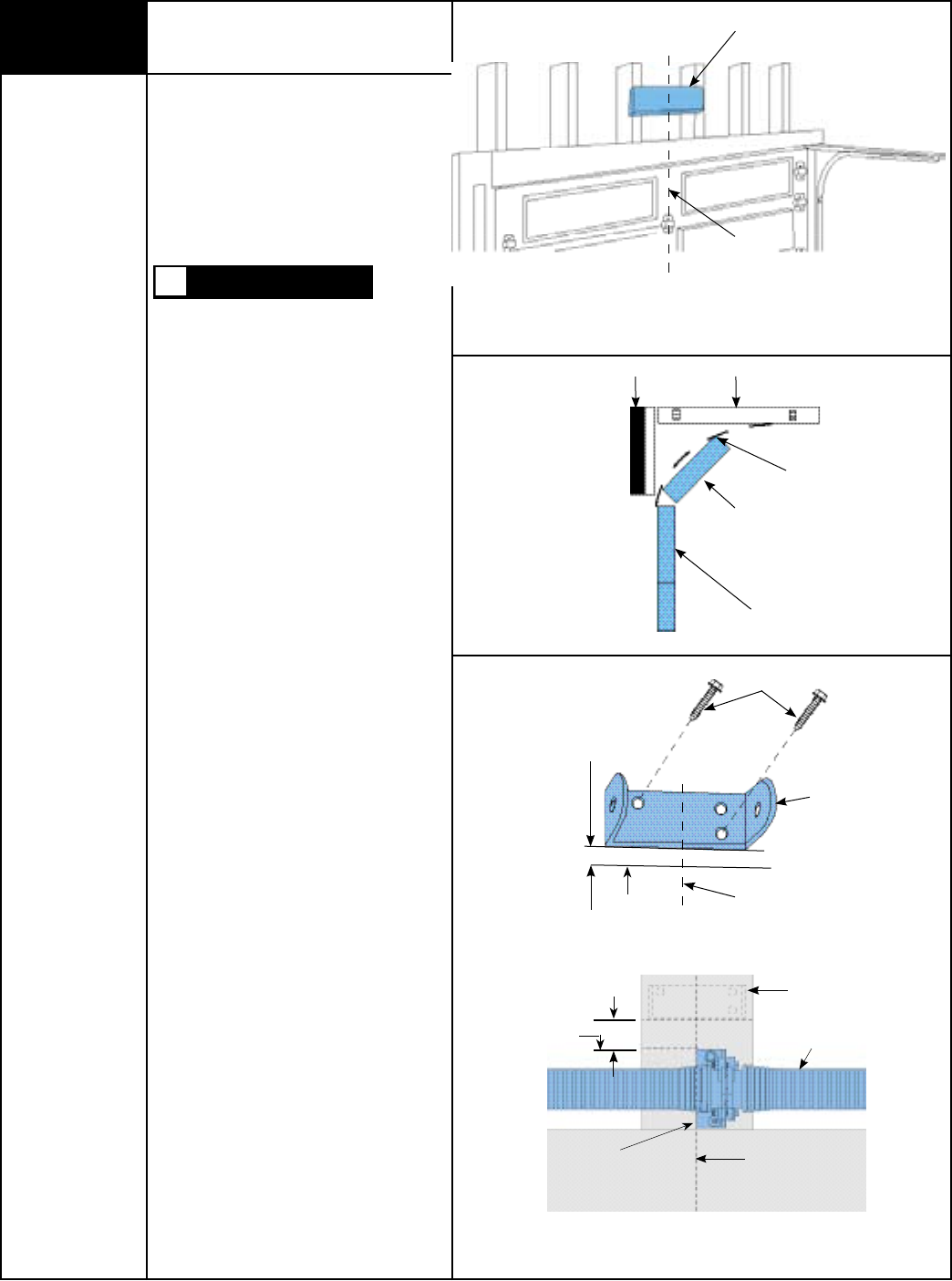
REINFORCE THE HEADER WALL
Reinforce the header wall (wall above door
opening) as required, to ensure rigid
mounting of the front wall bracket.
DO NOT ATTEMPT TO LOOSEN OR
REMOVE ANY PORTION OF DOOR SPRING
SYSTEM IN ORDER TO REINFORCE
HEADER WALL OR TO MOUNT WALL
BRACKET. SPRING SYSTEM IS UNDER
EXTREME TENSION AND CAN CAUSE
SEVERE OR FATAL INJURY. SUCH WORK
SHOULD BE DONE BY A QUALIFIED
SERVICE PERSON.
Locate the vertical center line of the garage
door and mark it on the header above the
door.
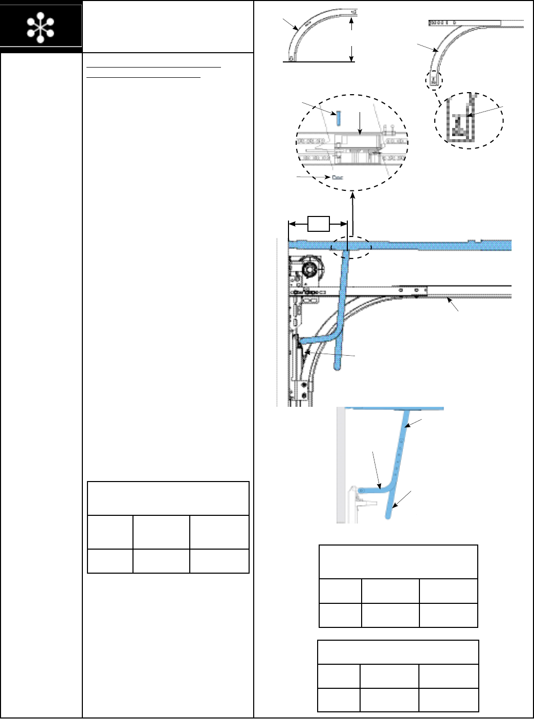
Raise the door slightly until the top section
reaches the highest point of travel (High Arc
Point); using a carpenter’s level, transfer
and mark the highest point of travel onto the
header wall and close the door.
Mount the front wall bracket with its lower
edge approximately 1/2” -1” above the
mark showing the highest point of travel and
centered on the vertical center line.
NOTE: For low headroom torsion
counterbalance, hold the wall bracket’s
bottom edge typically at 1/2” - 1” (room
permitting) above the torsion spring center
bracket and centered on the vertical line, see
illustration.
Mark the two mounting holes and pilot drill
with a 1/8” drill bit. Mount wall bracket using
the 1/4” x 1-1/2” lag screws supplied to
ensure rigid mounting.
WARNING
Reinforce with 2” x 6” as required to
insure rigid mounting.
Vertical Center Line
High Arc Point
Sectional Door
Curved Track
Carpenter’s Level
Tools Needed:
Carpenter’s Level
7/16” Socket
Driver
Power Drill
Tape Measure
1/8” Drill Bit
1/2” - 1” Above
High Arc Mark
Center of
Door
1/4” X 1 1/2”
Lag Screws
Front Wall
Bracket
Torsion Spring
Center Line
High Arc
Mark
Top Edge Of
Center Bracket
1/2” - 1” Above
Center Bracket
(Room Permitting)
Center Bracket
Top Section
Header
Front Wall
Bracket
Please Do Not Return This Product To The Store. Call Us Directly! Our Trained Technicians Will Answer Your Questions and/or Ship Any Parts You May Need
You can reach us Toll Free at 1-888-827-3667 for Consumer Assistance or online at www.wayne-dalton.com
3
Cardboard or Cloth to
Protect the Housing
Rail Assembly
3Attach Unit to Front Wall Bracket
Tools Needed:
7/16” Socket
Ratchet Wrench
Adjustable Wrench
Raise the front end of the rail
assembly and attach it to the front wall
bracket, using the 1/4” x 4” hex head bolt
and the supplied 1/4” plastic insert
locking nut. Take care not to over tighten
nut. Tighten only until end of bolt is flush
with outside of nut.
NOTE: If you have a torsion spring
counterbalance system, it will be necessary
to raise the opener and support it on a
step ladder to attach the front end of the rail
assembly to the wall bracket.
The upper door arm is secured to the spacer
bracket with one tie wrap for shipping.
Remove tie wrap attaching upper door arm
to the spacer bracket, allowing door arm to
swing down (see caution).
CAUTION: Support upper door arm with your
free hand, to prevent door arm from
swinging down uncontrolled.
4Positioning Motor
End of Opener
Tools Needed:
2” x 4” Board
Non-Metallic
Step Ladder
IMPORTANT: TO PREVENT DAMAGE TO
DOOR, DO NOT REST THE OPENER ON THE
DOOR WITHOUT USING A 2” X 4” BOARD
AT LEAST 3 FEET LONG.
Raise the motor end of the opener and
support it so you can open the door to its
fully open position. You may need help
raising motor end if ladder is not high
enough.
IMPORTANT: TO PREVENT DAMAGE TO
DOOR OR OPENER, POSITION TROLLEY AS
CLOSE TO OPENER AS POSSIBLE, BEFORE
OPENING DOOR.
Open the door and place a 2” x 4” x 36”
minimum board along the top section of the
garage door. Rest the rail assembly on the
2” x 4” board.
Support top section of door to prevent
excessive sagging.
Front Wall
Bracket
1/4” Plastic Insert
Locking Nut
1/4” x 4”
Hex Head Bolt
Non-Metallic
Step ladder
Support Door to
Prevent Sagging
Door
2” x 4”
Board
Opener
Rail Assembly
Tie Wrap Upper Door Arm
Spacer Bracket
Upper Door Arm
Trolley
Please Do Not Return This Product To The Store. Call Us Directly! Our Trained Technicians Will Answer Your Questions and/or Ship Any Parts You May Need
You can reach us Toll Free at 1-888-827-3667 for Consumer Assistance or online at www.wayne-dalton.com
4
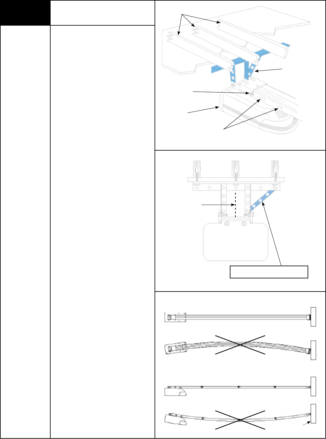
5Mounting Opener End
Tools Needed:
Power Drill
Hacksaw
1/8” Drill Bit
1/2” Socket
7/16” Socket
Ratchet Wrench
Adjustable Wrench
Tape Measure
Perforated Angle
Iron (Not Supplied)
CAUTION: Do not use gear cap bolt or nut
for hanger attachment. This may cause
sprocket, chain or Belt misalignment,
resulting in damage to opener or possible
personal injury!
Align the center of opener’s rail assembly
with the center line previously marked on
the top section of the garage door to ensure
rail will be parallel with the direction of door
travel.
Using perforated angles (cut to proper
length) hang opener end from ceiling joist.
Be sure to locate and mount to ceiling joists,
as illustrated.
Pilot drill with 1/8” drill bit and use
1/4” x 1-1/2” lag screws (not supplied) to
ensure a rigid mount. Attach opener to
perforated angles using 5/16” x 3/4” bolts
and 5/16” lock washer; nuts (not supplied).
NOTE: Bracing should be at an angle to
provide rigid support.
When opener is securely attached to
perforated angles, remove the 2” x 4” (used
to support rail assembly in Step 4) and
close the door.
NOTE: It is recommended that 10’ rails be
supported in the center to prevent sagging.
Opener rail should be aligned perpendicular
to the garage door when properly installed.
There should be no sagging of the rail in
any direction.
Ceiling Joist
Gear Cap
Nut/ Bolt
Opener
Cut Perforated
Angles to Fit
Alternate Hanger
Mounting Holes
Use angled brace to ensure rigid installation.
Center Line
Of Door
PROPER INSTALLATION
correct
incorrect
correct
incorrect
Top view
Side view
header
Please Do Not Return This Product To The Store. Call Us Directly! Our Trained Technicians Will Answer Your Questions and/or Ship Any Parts You May Need
You can reach us Toll Free at 1-888-827-3667 for Consumer Assistance or online at www.wayne-dalton.com
5
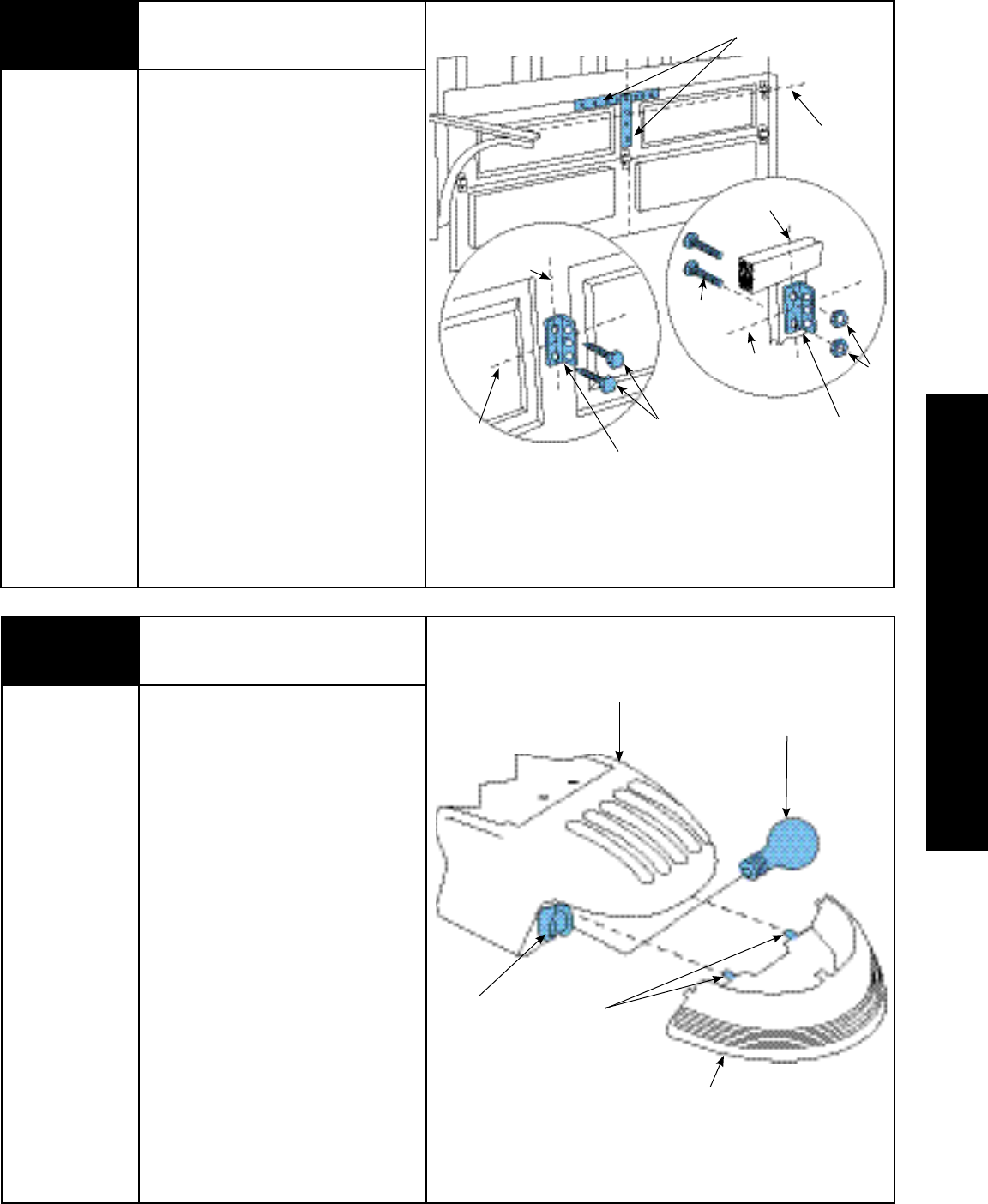
Mounting Door Bracket
Tools Needed:
7/16” Socket
Ratchet Wrench
NOTE: If you have a 5120, 5140, 9100,
9400, 9600, 9700 or 9800 series door,
do not install this door bracket, install the
door bracket supplied with the door, see the
Installation Instructions and Owner’s Manual
supplied with the door. Instructions manuals
are available for download at www.wayne-
dalton.com or call 1-888-827-3667.
IMPORTANT: DOORS MAY NEED TO BE
REINFORCED TO PREVENT DAMAGE TO THE
DOOR. CHECK WITH THE GARAGE DOOR
MANUFACTURER FOR PROPER
REINFORCING OF YOUR DOOR.
For wood doors, mount door bracket,
using two 1/4”-20 x 2” carriage bolts and
1/4” locking nuts supplied, on center line of
door with middle hole in line with top rollers.
For metal doors, mount door bracket,
using two 1/4”-20 x 5/8” self drilling screws
supplied, on center line of door with middle
hole in line with top rollers.
Door Center
Line
Door
Bracket
Top Roller
Guideline
Door Center
Line
Door
Bracket
Top Roller
Guideline
Top Roller
Guideline
Reinforce Door Vertically and
Horizontally
7Installing Light
Tools Needed:
None
Remove lens by pressing up on both sides
of the bottom of the lens at the junction of
the housing, releasing the locking tabs, and
pulling forward.
Screw a 60 watt (Maximum) bulb into
socket. For maximum bulb life, “rough
service” bulbs are recommended.
Align the top and bottom tabs on the lens
with the housing and push straight on until
lens locks in place.
Socket
Locking Tabs
Bulb - 60 Watt
Maximum
(Not Supplied)
Lens
Housing
6
STEEL
DOORS
WOOD
DOORS
1/4”-20 x 1/2”
Self Drilling Screws
1/4”-20 x 2”
Carriage Bolts
1/4”
Locking Nuts
PRE-OPERATION
Please Do Not Return This Product To The Store. Call Us Directly! Our Trained Technicians Will Answer Your Questions and/or Ship Any Parts You May Need
You can reach us Toll Free at 1-888-827-3667 for Consumer Assistance or online at www.wayne-dalton.com
6
Tools Needed:
Power Drill
Phillips Head
Screwdriver
Flat Tip
Screwdriver
3/32” Drill Bit
Wall Station Back
Wall Station Front
PB
COM
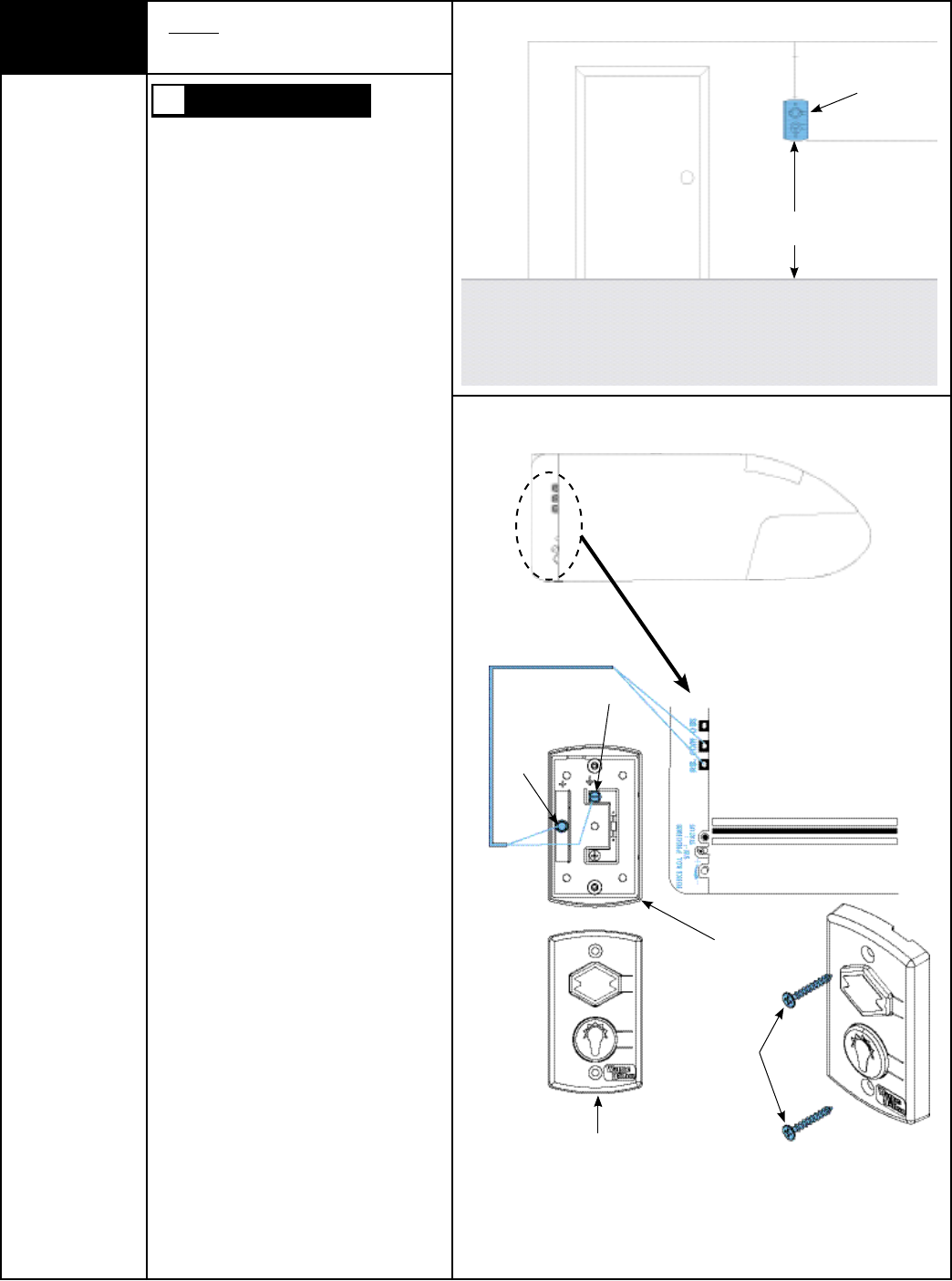
8
TO PREVENT POSSIBLE INJURY, INSTALL
WALL STATION OUT OF THE REACH OF
CHILDREN AND IN A LOCATION WHERE
THE DOOR CAN BE SEEN WHEN THE
OPENER IS ACTIVATED. DO NOT MOUNT
WALL STATION NEAR OR NEXT TO
GARAGE DOOR.
IMPORTANT: THE STANDARD PUSH
BUTTON OR THE DELUXE WALL
STATION MUST BE THE ONLY TYPE USED
FOR PROPER DOOR OPERATION. THE USE
OF AN ILLUMINATED PUSH BUTTON OR
WALL CONTROL STATION NOT SUPPLIED BY
WAYNE-DALTON COULD CAUSE OPENER TO
MALFUNCTION.
Wired Wall Station:
Wire the garage door opener wall station
using bell wire connected to COM and P.B.
screws, as illustrated.
Locate push button adjacent to service
entrance door at a minimum height of 5 ft.,
and at least 6 ft. away from garage door.
Fasten the wall station in a safe location with
the (2) phillips head screws, making sure not
to over tighten. Pilot drill mounting holes
using a 3/32” bit. Additional wired wall
stations may also be installed in accordance
with these instructions.
CAUTION: Over tightening the screws could
deform plastic case.
IMPORTANT: CONNECT THE LOW
VOLTAGE WIRE TO THE WALL STATIONS
USING A “J” HOOK CONFIGURATION. IF WIRE
IS COMPLETELY LOOPED AROUND
TERMINAL SCREW, IT CAN PREVENT
PROPER CONTACT.
Wired Wall Station Installation
(If Included)
Wall Station
5 Foot
Minimum
WARNING
Phillips Head Screws
Right Side Of Opener
Please Do Not Return This Product To The Store. Call Us Directly! Our Trained Technicians Will Answer Your Questions and/or Ship Any Parts You May Need
You can reach us Toll Free at 1-888-827-3667 for Consumer Assistance or online at www.wayne-dalton.com
7
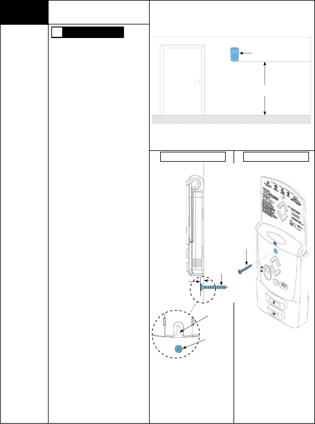
9Deluxe Multi-Function Wireless
Wall Station Installation
(If Included)
Tools Needed:
Power Drill
3/32” Drill Bit
Phillips Head
Screwdriver
TO PREVENT POSSIBLE INJURY, INSTALL
WALL STATION OUT OF THE REACH OF
CHILDREN AND IN A LOCATION WHERE
THE DOOR CAN BE SEEN WHEN THE
OPENER IS ACTIVATED. DO NOT MOUNT
WALL STATION NEAR OR NEXT TO
GARAGE DOOR.
NOTE: For proper operation, mount the wall
station on a flat surface.
The wall station can be mounted to a NEMA
standard electrical box or directly to any wall
surface. No wiring is required.
Locate wall station adjacent to service
entrance door at a minimum height of 5 ft.,
and at least 6 ft. away from garage door.
If mounting to a NEMA electrical box, use
machine thread screws provided in place of the
wood screws. No drilling is required. If high
voltage wiring is contained in the box,
a standard NEMA solid faceplate must be
installed between the box and the wall station. If
fastening into drywall or concrete, use anchors
provided. When mounting to wood use a 3/32"
drill bit and the drilling template located on
page 39. Drill the two 3/32” mounting holes
using the drill template. Drill 3/16" holes if
using anchors.
Install lower screw leaving 3/16" of the screw
exposed. Slide wall station keyhole slot onto the
lower phillips head screw. Wall station should
slide onto screw, providing a snug fit. If
necessary remove wall station and loosen or
tighten lower phillips head screw until a snug fit
is achieved.
Once wall station is fitted on lower screw, install
upper screw. Do not over-tighten.
CAUTION: Over tightening the upper screw
could deform plastic case.
WARNING
Wall Station
5 Foot
Minimum
Lower Screw Installation Upper Screw Installation
3/16”
Keyhole
Slot
Phillips
Head Screw
Phillips
Head Screw
Phillips Head
Screw
Please Do Not Return This Product To The Store. Call Us Directly! Our Trained Technicians Will Answer Your Questions and/or Ship Any Parts You May Need
You can reach us Toll Free at 1-888-827-3667 for Consumer Assistance or online at www.wayne-dalton.com
8
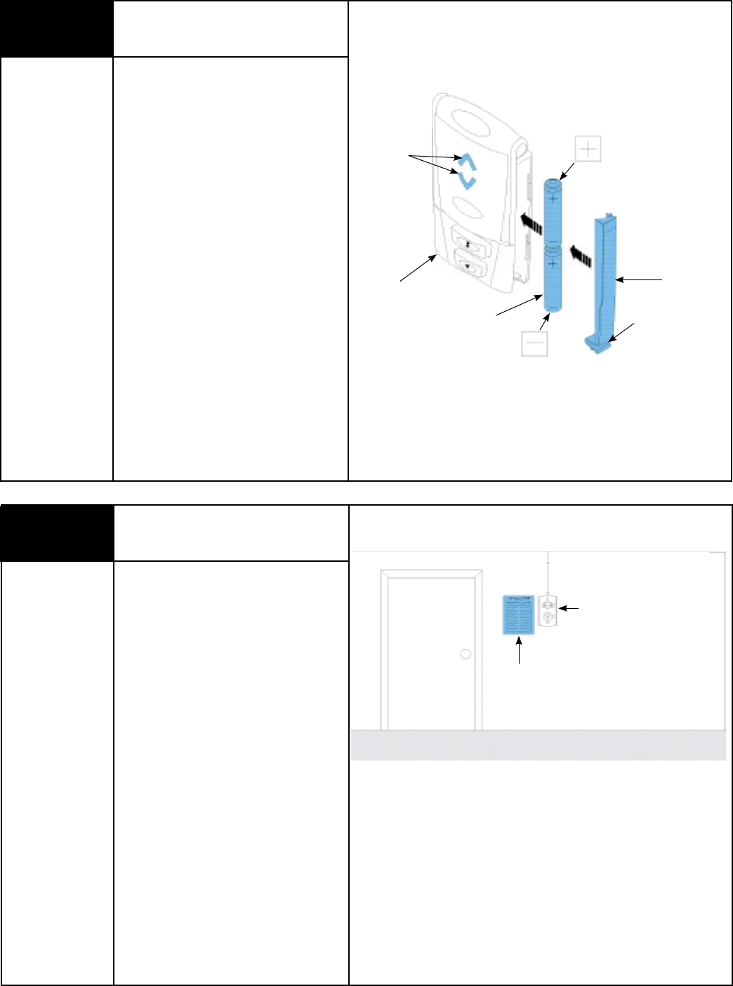
Battery
Cover
Up/Down
LED
Wall
Station
(2) AAA
Batteries Lower
Clip
10 Entrapment
Warning Label
Tools Needed:
None
Apply entrapment label in a convenient
location next to the wall station. Use
mechanical fasteners if adhesive will not
adhere. Service
Entrance
Door
Entrapment
Warning Label
Wall Station
Deluxe Multi-Function Wireless
Wall Station Installation Continued
(If Included)
Remove the battery cover (right-hand side of
wall station) by disengaging the battery cover’s
lower clip. Install two AAA batteries into the wall
station observing the polarity, (+) and (-), of
both batteries. After about three seconds, the
Up/Down red LED will begin to blink every 5
seconds. Re-install the battery cover by first
inserting its top into the wall station then
inserting and securing its bottom.
NOTE: To slow blink rate or turn off, refer to
wall station operation page 28 “Back Lit LED
Lights”.
Please Do Not Return This Product To The Store. Call Us Directly! Our Trained Technicians Will Answer Your Questions and/or Ship Any Parts You May Need
You can reach us Toll Free at 1-888-827-3667 for Consumer Assistance or online at www.wayne-dalton.com
9
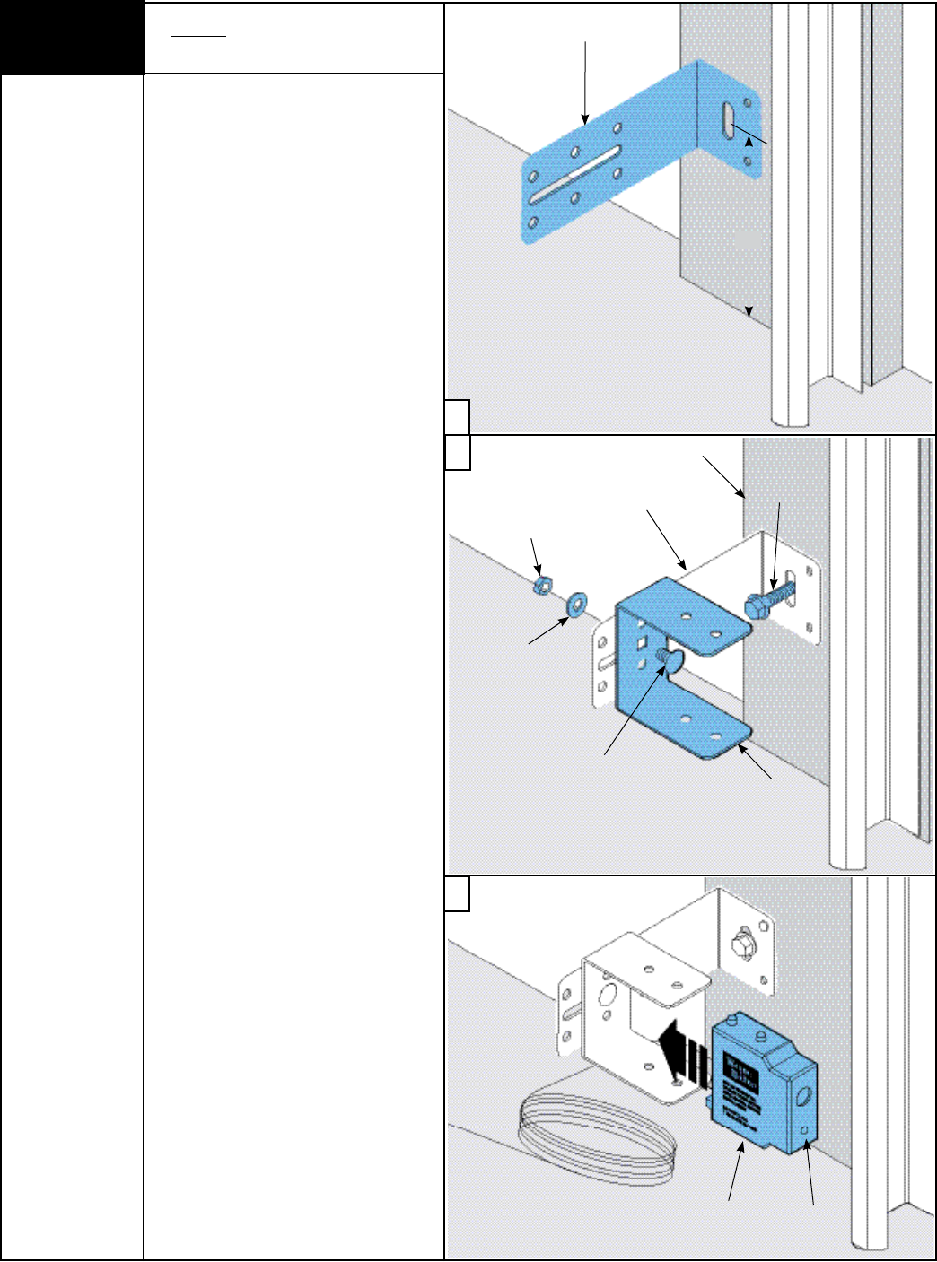
11 Wired Infrared Safety Sensor
Installation
Tools Needed:
Ratchet Wrench
Tape Measure
Power Drill
3/16” Drill Bit
7/16” Socket
Driver
7/16” Wrench
Pencil
IMPORTANT: BOTH WALL BRACKETS
MUST BE MOUNTED AT THE SAME HEIGHT
FOR PROPER ALIGNMENT.
Note: Use Steps a-c for installing sensors
on both sides of the garage door.
a. Select and mark with a pencil, a
mounting location no more than
5 inches above the floor to center line of
wall mounting bracket. The safety sensors
should be mounted as close to the door
track or inside edge of the door as
possible to offer maximum entrapment
protection. It is very important that both
wall mounting brackets be mounted at
the same height for proper alignment.
b. Drill pilot holes, using a 3/16” drill bit.
Using two 5/16” x 1-1/2” lag screws,
permanently mount the wall mounting
brackets to both door jambs. In some
installations it may be necessary to attach
a wooden spacer to the wall to achieve
the required alignment.
Attach the “U” brackets to the wall
mounting brackets with 1/4”-20 x 1/2”
carriage bolts, washers and nuts.
Insert the bolts from the inside of the
“U” bracket and hand-tighten.
IMPORTANT: IDENTIFY WHICH SIDE OF THE
GARAGE DOOR IS EXPOSED TO THE MOST
SUNLIGHT. MOUNT THE SENDING UNIT (UNIT
WITHOUT LED) ON THE SIDE WHICH IS
EXPOSED TO THE MOST SUN. SUNLIGHT
MAY AFFECT THE SAFETY SENSORS, AND
THIS ORIENTATION WILL HELP REDUCE THE
EFFECT.
c. Attach the sending and receiving safety
sensors to the “U” brackets by inserting
all three tabs into the respective holes.
Wall Mounting Bracket
5”
Washer
Nut
1/4”-20 x 1/2”
Carriage Bolt
5/16” x 1-1/2”
Lag Screw
Door Jam
U-Bracket
Wall Mounting
Bracket
Receiving
Unit LED
a
c
b
Please Do Not Return This Product To The Store. Call Us Directly! Our Trained Technicians Will Answer Your Questions and/or Ship Any Parts You May Need
You can reach us Toll Free at 1-888-827-3667 for Consumer Assistance or online at www.wayne-dalton.com
10
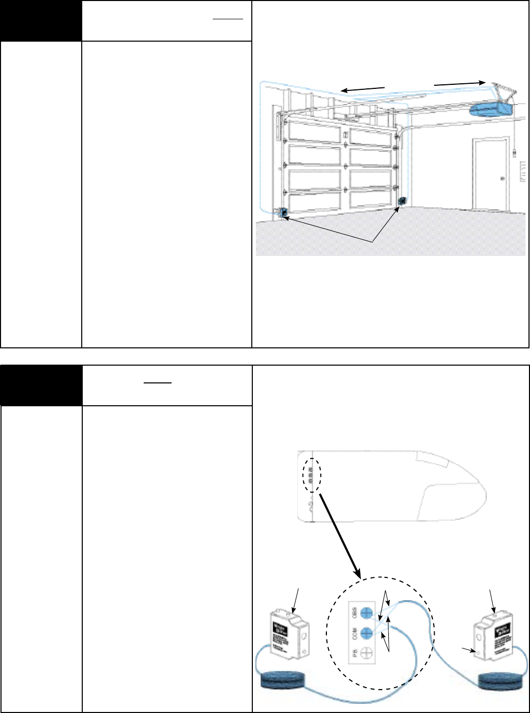
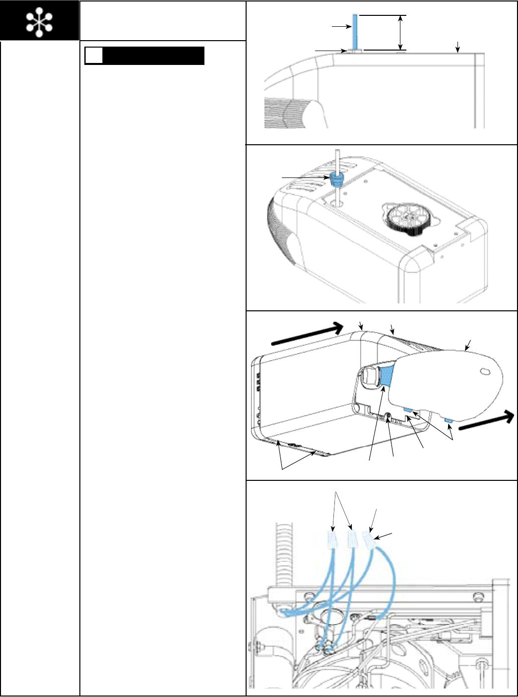
12 Installation of Wiring for Wired
Infrared Safety Sensor
Tools Needed:
Hammer
Uncoil the wires from the infrared safety
sensors and route the wire up the garage
wall across the ceiling and down to the back
of the opener. Tack the wires in place using
staples (Not Supplied). Take care to run
the wires in a location where they will not
interfere with the operation of the door and
do not staple through wire.
NOTE: If wires must be lengthened or
spliced into pre wired installation, use wire
nuts or other suitable connectors.
To Opener
Wire to Opener
13 Connecting Wired Infrared Safety
Sensor to Opener
Tools Needed:
Phillips Head
Screwdriver
Connect infrared safety sensors to the
opener as shown. Shorten wires as
necessary and separate wire ends. Strip
about 1/2” of insulation off each wire, being
careful not to nick wires, and attach wires
to the proper terminal screws, then tighten
securely, using phillips head screwdriver.
One wire has marking on it (numbers, black
stripe, etc). Be sure to observe polarity. Apply
tension to external wires to test for secure
connection. Check that the wires are stapled
in place properly.
Sending Unit Receiving Unit
Black Strip
Solid
Color
Right Side Of Opener
LED
Please Do Not Return This Product To The Store. Call Us Directly! Our Trained Technicians Will Answer Your Questions and/or Ship Any Parts You May Need
You can reach us Toll Free at 1-888-827-3667 for Consumer Assistance or online at www.wayne-dalton.com
11
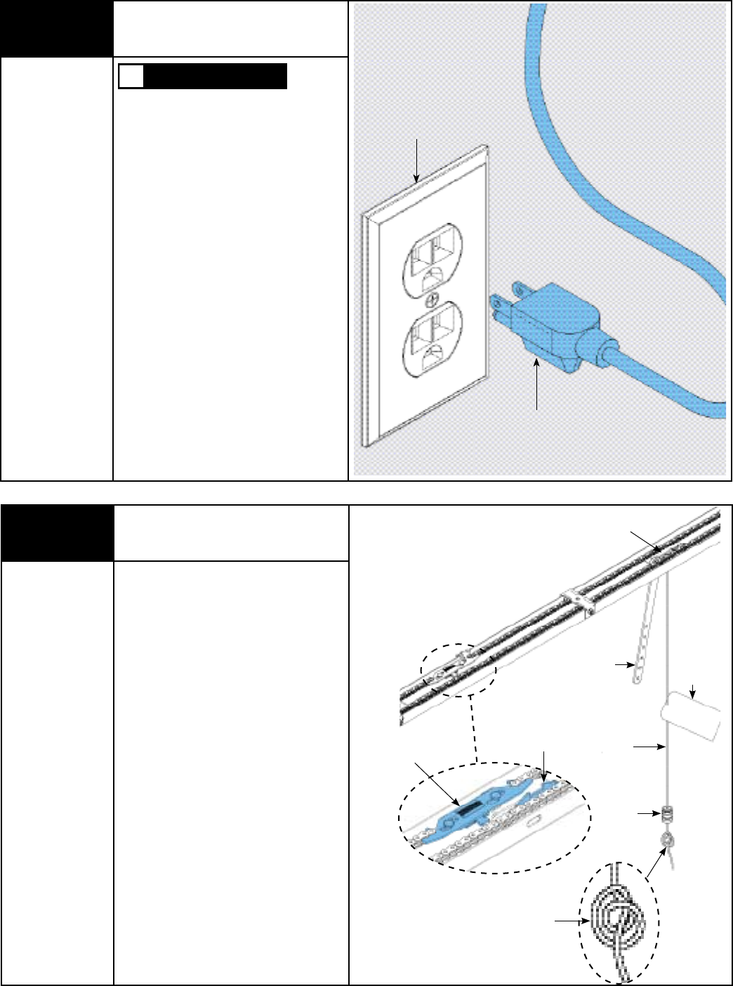
14 Connecting Opener
To Outlet
Tools Needed:
None TO REDUCE THE RISK OF ELECTRICAL
SHOCK, DO NOT CHANGE THE POWER
CORD IN ANYWAY.
IMPORTANT: THE OPENER MUST BE
CONNECTED TO A PROPERLY GROUNDED 3
PRONG, 120 VOLT OUTLET.
The opener can be permanently wired. To
permanently wire the unit, see permanent
wiring option on page 20.
Plug the power cord into the closest
grounding type receptacle. Excess power
cord length must be routed and contained
safely away from any moving parts.
As soon as power is applied to the opener,
the light on the opener will blink once to
indicate a successful self-check of the
controls.
WARNING
Outlet
Power Cord
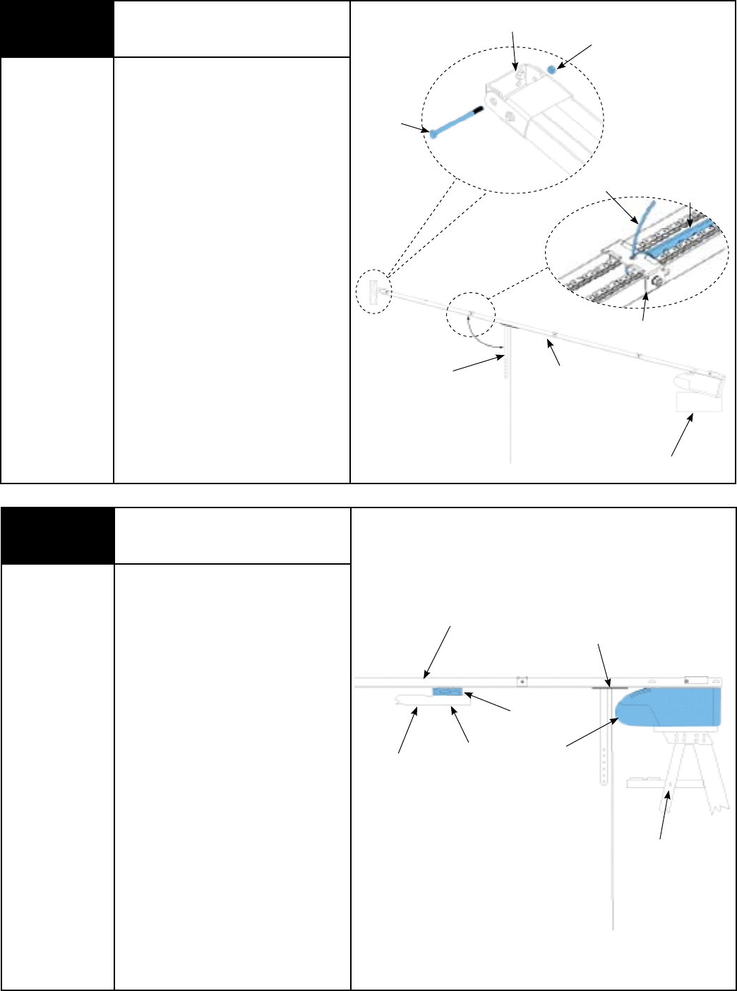
15 Connecting Trolley
To Latch Assembly
Tools Needed:
None
Slide the trolley until it snaps onto the latch
assembly.
Attach warning label to the red release cord.
Thread the red release cord through the pull
knob so knot is inside pull knob. Tie a double
knot at the end of the red release cord to
secure pull knob.
NOTE: Pull knob should hang 6 feet above
floor. Ensure that the rope and handle clear
the tops of all vehicles to avoid
entanglement.
Latch Assembly
Trolley
Upper Door Arm
Release Cord
Pull Knob
Tag
Use a Double Knot
To Secure The Red
Pull Knob
Trolley
Please Do Not Return This Product To The Store. Call Us Directly! Our Trained Technicians Will Answer Your Questions and/or Ship Any Parts You May Need
You can reach us Toll Free at 1-888-827-3667 for Consumer Assistance or online at www.wayne-dalton.com
12
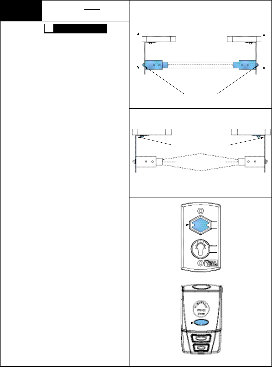
16 Alignment of Wired Infrared
Safety Sensors
Tools Needed:
Pliers TO AVOID POSSIBLE SEVERE OR FATAL
INJURY, KEEP PEOPLE AND OBJECTS
CLEAR OF THE MOVING DOOR ARM TO
PREVENT POSSIBLE PERSONAL INJURY.
IMPORTANT: THE SAFETY SENSOR SENDS
AN INVISIBLE BEAM OF LIGHT FROM THE
SENDING UNIT TO THE RECEIVING UNIT
ACROSS THE PATHWAY OF THE DOOR. THE
OPENER WILL NOT OPERATE UNTIL THE
SAFETY SENSORS ARE CONNECTED TO THE
OPENER AND PROPERLY ALIGNED. IF THE
INVISIBLE BEAM OF LIGHT IS OBSTRUCTED,
AN OPEN DOOR CANNOT BE CLOSED BY
THE TRANSMITTER OR A MOMENTARY
ACTIVATION OF THE WALL STATION UP/
DOWN BUTTON. HOWEVER, THE DOOR MAY
BE CLOSED BY CONTINUOUSLY
HOLDING YOUR FINGER ON THE WALL
STATION UP/DOWN BUTTON (CONSTANT
PRESSURE) UNTIL THE DOOR TRAVELS TO A
FULLY CLOSED POSITION.
At this point you will be able to activate the
opener. The trolley/ upper arm will move
to the open position, but will not move to
the closed position unless the beams are
aligned.
The safety sensors must be aligned by
moving the sending and receiving units in or
out until the alignment light on the receiving
unit comes on. The 1/4”-20 carriage bolt
can be loosened to move the unit in or out,
as required. If you have difficulty
aligning beams, check that both brackets are
mounted at the same height (see Step 11)
and remount if necessary. Additional minor
adjustments can be made by lightly bending
the mounting brackets.
Once the alignment light comes on, tighten
all bolts and mounting screws.
Finish securing all wiring making sure not to
break or open any of the conductors. Loop
and secure any extra wire.
Using the wall station up/down button,
activate the opener and check that it will
operate through full open and close. Ensure
trolley and trolley latch are in the closed
position prior to proceeding to next step.
1/4”-20 Carriage Bolts
In
Out
In
Out
Top View
For this adjustment, bend mounting brackets
at wall mount
Up/Down
Button
Up/Down
Button
Wired Wall station
Multi-Function Wall Station
RF Transmitter
WARNING
Please Do Not Return This Product To The Store. Call Us Directly! Our Trained Technicians Will Answer Your Questions and/or Ship Any Parts You May Need
You can reach us Toll Free at 1-888-827-3667 for Consumer Assistance or online at www.wayne-dalton.com
13
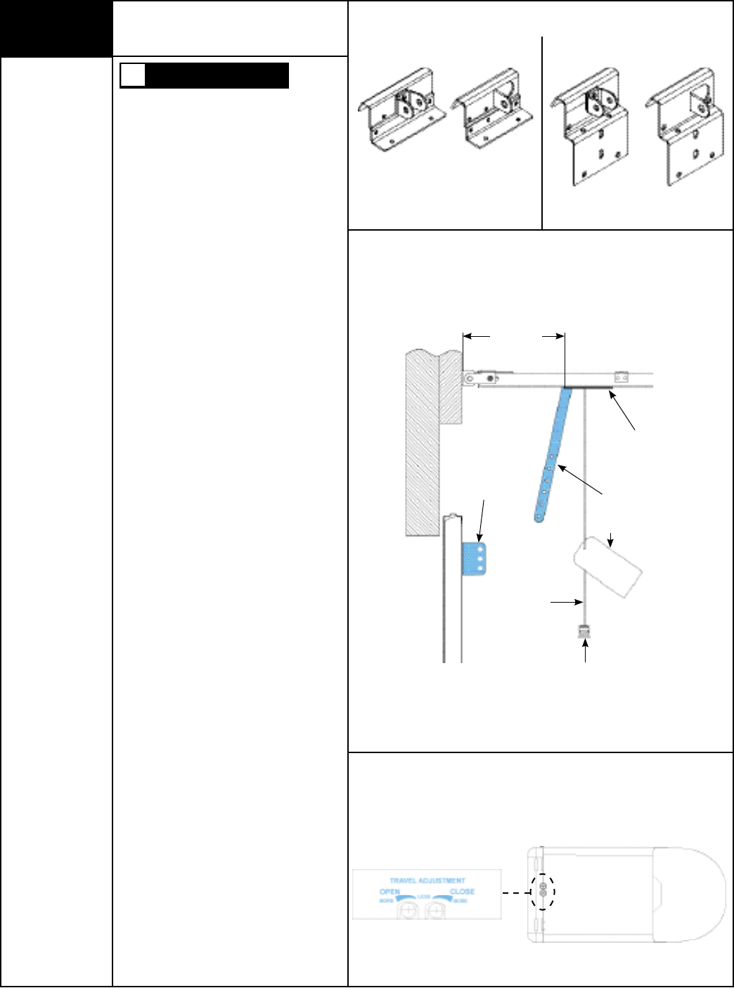
Setting Trolley Close Position
17
Tools Needed:
Pliers/Wire Cutters
Tape Measure
Flat Tip
Screwdriver
Bottom Of Opener
Door Bracket Upper Arm
Trolley
(Closed Limit Position)
11” to 13”
(13” Minimum
For Belt Drive)
Pull Knob
Release Cord
Tag
WARNING
Models: 9100, 9400, 9600, 5120 and 5140.
Single and Double Tab Door Brackets
Model: 9700
Single Tab
Bracket
Double Tab
Bracket
Single Tab
Bracket
Double Tab
Bracket
TO AVOID POSSIBLE INJURY OR
PROPERTY DAMAGE, KEEP PEOPLE AND
OBJECTS CLEAR OF THE MOVING DOOR
ARM.
NOTE: If necessary, activate the opener
to move the trolley/ upper door arm to the
closed position.
NOTE: If you have a 9100, 9400,9600,
5120, 5140 or 9700 series door, with one of
the door brackets shown at the right and a
Torquemaster® or Extension Spring(s)
counterbalance system, see “Setting Trolley
Close Position/ Connecting Door Arm To
Door” on pages 23-24. If not, complete this
step.
NOTE: If you have a 9100, 9400, 9600,
5120, 5140 or 9700 series door, with one of
the door brackets shown at the right and a
Torsion Spring(s), see “Setting Trolley Close
Position/ Connecting Door Arm To Door” on
pages 25-26. If not, complete this step.
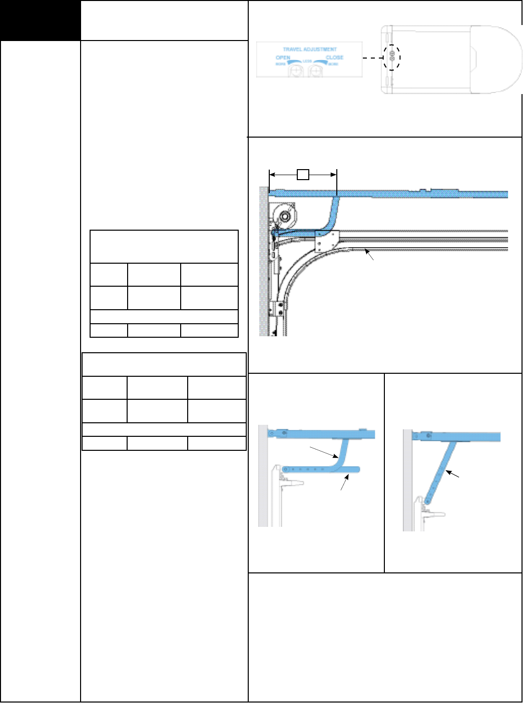
Trolley and latch assembly must be at the
factory preset fully closed position, (see
illustration).
Verify preliminary trolley and latch assembly
close position is 11” to 13” between trolley
clevis pin and the inside face of the door.
If adjustment of the trolley/latch assembly
position is required, use the close travel
adjustment screw located on the bottom of
the opener. A 1/4 turn equals approximately
1” of trolley travel; turn clockwise to de-
crease distance between header and trolley
and counter-clockwise to increase distance
between header and trolley.
Please Do Not Return This Product To The Store. Call Us Directly! Our Trained Technicians Will Answer Your Questions and/or Ship Any Parts You May Need
You can reach us Toll Free at 1-888-827-3667 for Consumer Assistance or online at www.wayne-dalton.com
14
Typical Installation:
Place nylon shoulder bushing in lower arm
hole in curved end (single hole). Place door
arm on right side of door bracket. Insert
5/16” x 1-1/4” multi-grip clevis pin through
nylon shoulder bushing, lower door arm and
middle hole of door bracket. Install hairpin
cotter through hole (Closest to door bracket)
of multi grip clevis, as shown.
For Models: 9100, 9400, 9600, 5120,
5140 And 9700
Place nylon shoulder bushing in lower arm
hole in curved end (single hole). Place the
lower door arm between the tabs (or the right
side of single tab) and insert 5/16” x 1-1/4”
multi-grip clevis pin through nylon shoulder
bushing, lower door arm and hole(s) of door
bracket. Install hairpin cotter through hole
(Closest to door arm “Double Tab” or door
bracket “Single Tab”) of multi grip clevis, as
shown.
For Models: 9700 And 9800
Place nylon shoulder bushing in lower arm
hole in curved end (single hole). Place the
lower door arm between the tabs and insert
5/16” x 1-1/4” multi-grip clevis pin through
nylon shoulder bushing, lower arm and holes
of door bracket. Install hairpin cotter through
hole (Closest to door arm) of multi grip clevis,
as shown.
CONNECTING UPPER AND LOWER DOOR
ARMS
FAILURE TO USE LOCKING NUT CAN
RESULT IN ARM RELEASING AND
POSSIBLE RESULTING IN PROPERTY
DAMAGE AND/OR PERSONAL INJURY.
Align upper and lower door arm pieces to
nearest matching holes.
NOTE: It may be necessary to apply down-
ward pressure on the door or slightly raise
the door during this process.
Secure upper and lower door arms to each
other using two 1/4”-20 x 3/4” hex head
bolts and nylock nuts.
NOTE: Install the hex head bolts as far apart
as possible, when positioning the upper and
lower arms.
NOTE: Door arm angle must be 10° to 30°
degrees (see illustration). If not, repeat “Set-
ting Trolley Close Position” and increase or
decrease distance between trolley clevis pin
and inside face of the door.
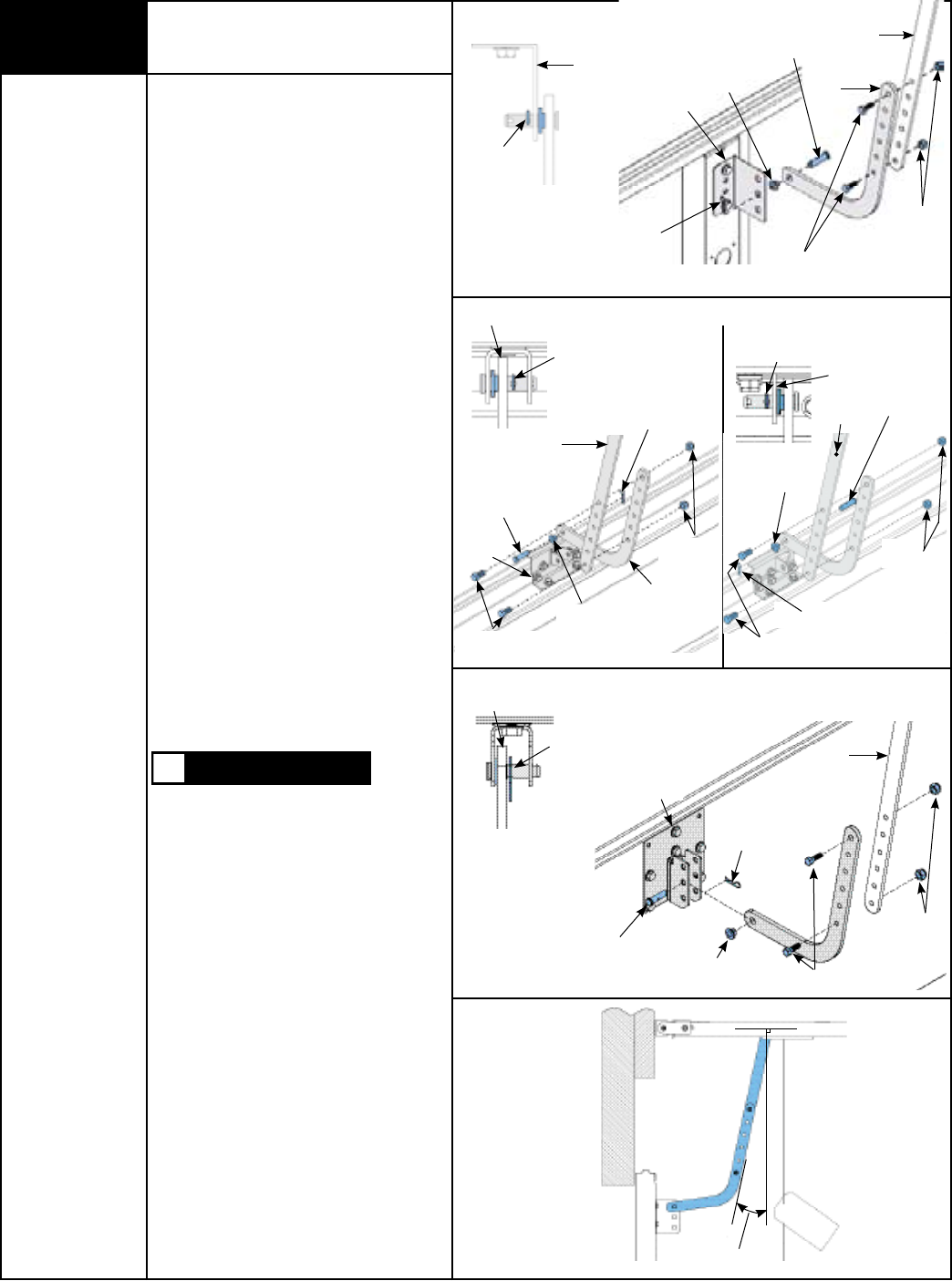
18 Connecting Door Arm to Door
Tools Needed:
Adjustable Wrench
Ratchet Wrench
7/16” Socket
9/16” Socket
WARNING
Typical Installation
10° To 30°
5/16” x 1-1/4”
Multi-grip Clevis pin
1/4”-20 x 3/4”
Hex Head Bolt
Nylon Shoulder
Bushing
Hairpin Cotter
Lower Arm
Upper Arm
1/4”
Nylock Nuts
Door Bracket
TOP VIEW
Hairpin Cotter
(Hole Closest to
Door Bracket)
Models: 9700 And 9800
Single TabDouble Tab
TOP VIEW
TOP VIEW
Models: 9100, 9400,9600, 5120, 5140 or 9700
TOP VIEW
Hairpin Cotter
Door
Bracket
Nylon Shoulder
Bushing
5/16” x 1-1/4”
Multi-grip Clevis pin
Lower Arm
Upper Arm
1/4”
Nylock Nuts
1/4”-20 x 3/4”
Hex Head Bolt
Hairpin Cotter
(Hole Closest to
Door Arm)
Lower Arm
Door Bracket
Hairpin Cotter
(Hole Closest to
Door Bracket)
Door Bracket
Lower Arm
Hairpin Cotter
(Hole Closest to
Door Arm)
Door
Bracket
5/16” x 1-1/4”
Multi-grip Clevis pin
1/4”-20 x 3/4”
Hex Head Bolt
Nylon Shoulder
Bushing
Lower Arm
1/4”
Nylock Nuts
Hairpin Cotter
Upper Arm
1/4”
Nylock Nuts
Hairpin
Cotter
Upper Arm
5/16” x 1-1/4”
Multi-grip Clevis pin
Door
Bracket
Nylon Shoulder
Bushing
1/4”-20 x 3/4”
Hex Head Bolt
Lower Arm
Please Do Not Return This Product To The Store. Call Us Directly! Our Trained Technicians Will Answer Your Questions and/or Ship Any Parts You May Need
You can reach us Toll Free at 1-888-827-3667 for Consumer Assistance or online at www.wayne-dalton.com
15
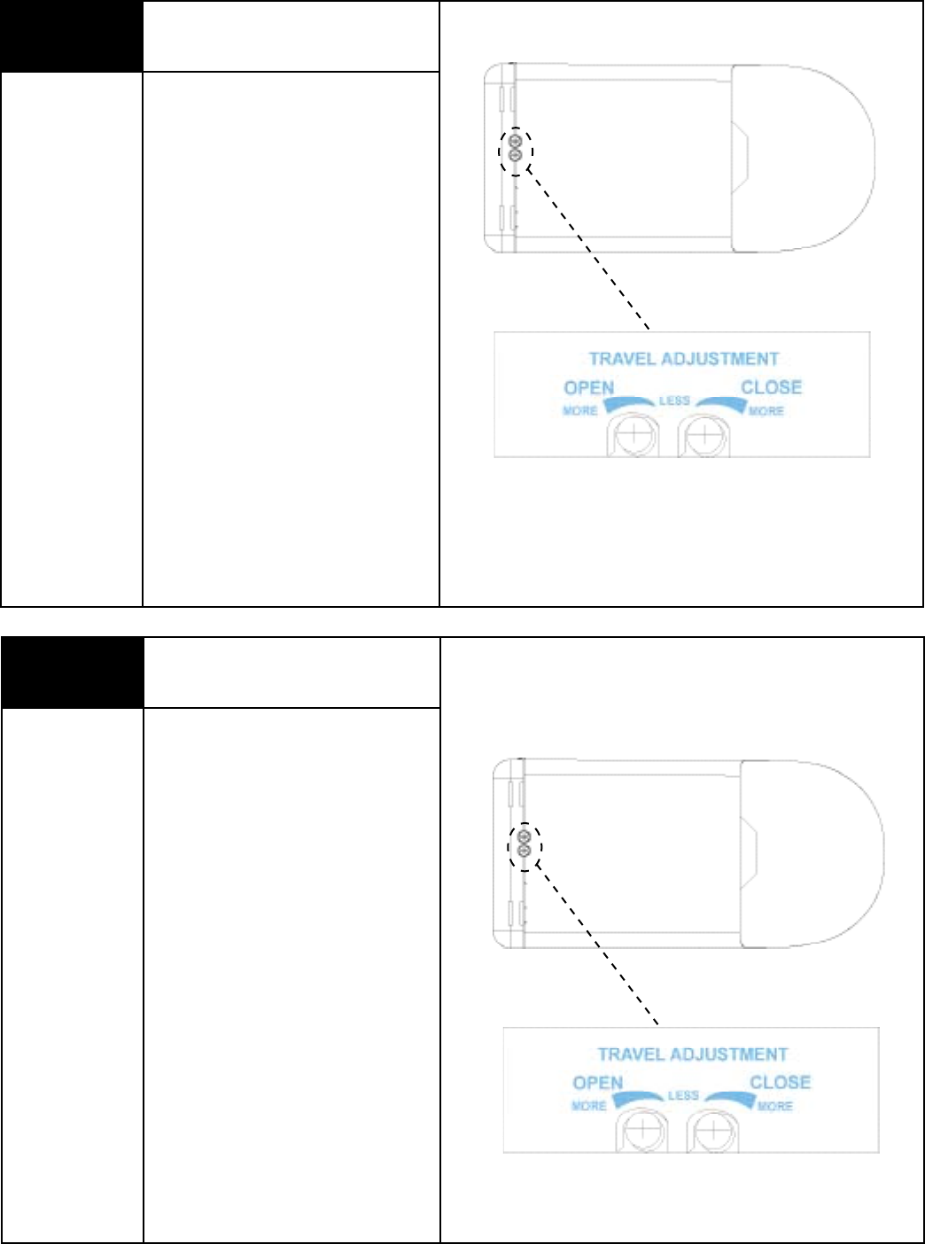
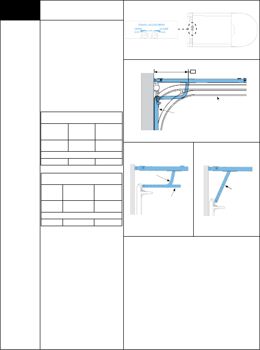
19 Setting Door Close Travel
Tools Needed:
Flat Tip
Screwdriver
Using the wall control up/down button,
activate door to full open position;
reactivate to close position.
The door should stop on the floor with the
bottom door seal slightly compressed.
If the door reverses off the floor, turn close
travel knob 1/4 turn “less”.
If door is not completely closed, turn travel
knob 1/4 turn “more”.
Repeat as necessary.
NOTE: 1/4 turn equals 1” of door travel.
Bottom Of Opener
Bottom Of Opener
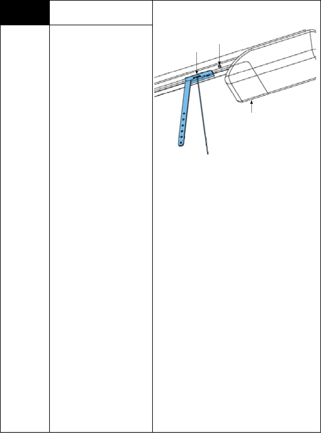
20 Setting Door Opening Travel
Tools Needed:
Flat Tip
Screwdriver
The door opener is assembled with the open
travel adjustment preset for a typical door,
but all doors should be adjusted to stop as
close as possible to the door’s “natural” fully
open, resting position.
To determine the door’s “natural” fully open,
resting position, disconnect door from
opener using the emergency release
disconnect (see page 27, EMERGENCY
DISCONNECT) and manually raise door to its
“natural” fully open, resting position. Use this
location for your open limit setting. To
determine if door needs adjustment, activate
the opener to bring door to fully open
position.
Please Do Not Return This Product To The Store. Call Us Directly! Our Trained Technicians Will Answer Your Questions and/or Ship Any Parts You May Need
You can reach us Toll Free at 1-888-827-3667 for Consumer Assistance or online at www.wayne-dalton.com
16
Setting Door Opening Travel
(Continued)
NOTE: If door does not open fully and
opener light flashes (make sure the bulb
is installed and operating) check for an
obstruction or see Adjustment #1, page 32
(Adjusting Opening Force).
To adjust for a non-standard door or to
precisely set the open position: Using
the wall station, operate the door and stop
it in mid-travel position. Using a flathead
screwdriver turn the OPEN travel adjuster for
more (counter-clockwise) or less (clockwise)
travel. A 1/4 turn equals approximately 1” of
trolley movement.
NOTE: Confirm that the door has stopped in
the UP position as a result of the upper limit
switch and not because the trolley has hit
the stop bolt, which is mounted in the rail
near the opener. The correct condition can
be verified by observing that the openers
convenience light does not flash after the
fully open door comes to a stop. The faulty
condition may also be confirmed visually
by checking to see if the trolley is resting
against the stop bolt.
To confirm final OPEN travel adjustment,
activate the opener to bring door to fully
open position. The opener light should not
be flashing.
Opener
Trolley
Stop Bolt
Please Do Not Return This Product To The Store. Call Us Directly! Our Trained Technicians Will Answer Your Questions and/or Ship Any Parts You May Need
You can reach us Toll Free at 1-888-827-3667 for Consumer Assistance or online at www.wayne-dalton.com
17
Safety Sensor Obstruction Test
Tools Needed:
2” x 6” x 12”
Solid Test Object
Sensor
12”
Sensor
12”
6”
WHEN PERFORMING THIS PART OF THE
TEST, DO NOT PLACE YOURSELF UNDER
DESCENDING DOOR, OR SEVERE OR
FATAL INJURY MAY RESULT.
Starting with the door fully open, place a 6”
high object on the floor, in line with sensors,
12” from the left side of the door.
Activation of the opener with the wall station
Up/Down button should cause the door to
move no more than one foot, stop and then
reverse to fully open position.
Repeat this test with the 6” high object
placed at the center of the door and then
12” from the right side of the door.
The 6” high object, when placed on the floor
in line with sensors, while door is closing,
should also cause the door to reverse.
WARNING
22
IF OPENER DOES NOT RESPOND PROPERLY TO THESE TESTS (STEPS
21 AND 22), HAVE A QUALIFIED SERVICE PERSON MAKE NECESSARY
ADJUSTMENTS/REPAIRS, OR SEVERE OR FATAL INJURY COULD RESULT
FROM OPERATING THE DOOR/OPENER.
WARNING
21 Contact Obstruction Test
Tools Needed:
2 x 4 Board
After installing the opener, the door must
reverse when it contacts a 1 1/2” inch high
object (or a 2 x 4 board laid flat) on the
garage floor.
Using the wall station, activate the door to
the fully open position. Place a 2 x 4 flat
on the garage floor, under the door path.
Activate the door to the closed position with
the wall station. Upon contacting the 2 x 4
board, the door should reverse.
If door stops on the 2 x 4 board, adjust
the close travel knob 1/8-1/4 turn “more”
until door reverses upon contact with 2 x 4
board.
When the door reverses, remove the
2 x 4 board and run the full cycle of open
and close of the door. Door should not
reverse when it comes to the fully closed
position on the floor.
NOTE: If opener fails to pass this test,
repeat Step 19. Also see Adjustment #2,
page 32 (Contact Obstruction Test).
2 x 4 Laid Flat
On The Floor
IF OPENER DOES NOT RESPOND PROPERLY TO THESE TESTS (STEPS
21 AND 22), HAVE A QUALIFIED SERVICE PERSON MAKE NECESSARY
ADJUSTMENTS/REPAIRS, OR SEVERE OR FATAL INJURY COULD
RESULT FROM OPERATING THE DOOR/OPENER.
WARNING
Please Do Not Return This Product To The Store. Call Us Directly! Our Trained Technicians Will Answer Your Questions and/or Ship Any Parts You May Need
You can reach us Toll Free at 1-888-827-3667 for Consumer Assistance or online at www.wayne-dalton.com
18
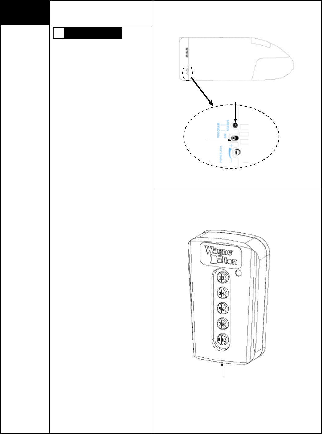
23 Programming Wireless Keyless
Entry (If Included)
Tools Needed:
None
Program Status
LED
Program
Button
Right Side Of Opener
Keyless Entry
DURING PROGRAMMING THE GARAGE
DOOR MAY OPERATE. KEEP PEOPLE AND
OBJECTS CLEAR OF THE MOVING DOOR
TO PREVENT DOOR DAMAGE OR
POSSIBLE PERSONAL INJURY.
NOTE: To simplify installation, program the wire-
less keyless entry to the opener before mounting
to the wall.
NOTE: Before programming ensure garage door
is in the “down” position.
1. Press and release the PROGRAM button. The
red PROGRAM STATUS light on the opener and
the overhead lamp will turn on and remain lit for
one minute, indicating that it is ready to learn the
keyless entry.
2. Press the desired five digit PIN (PERSONAL
IDENTIFICATION NUMBER), example 1-3-8-2-5.
The PROGRAM STATUS light will turn on and off
three times indicating a successful learn.
NOTE: Do not set a code that presents the num-
bers in sequential order, as an example 1/2, 3/4,
5/6, 7/8, 9/0. Studies show that people naturally
press the buttons in a sequential pattern. Also,
do not select a code that uses the same button
five times consecutively. Thieves can easily
figure out these types of codes.
NOTE: If at anytime, an error was made entering
the code, simultaneously press and release the
7/8 and 9/0 buttons to reset the keyless entry;
then repeat programming steps above.
NOTE: A single wireless keyless entry device may
be programmed to operate multiple garage door
openers. To program additional openers, repeat
programming steps using a different five digit PIN
for each additional opener.
How Your Keyless Entry Operates Your Door:
The following explains how your Keyless Entry
can be used to OPEN, CLOSE, START, and STOP
your door.
1. Enter your 5-digit PIN (personal identification
number); door will move.
NOTE: If you inadvertently enter an incorrect
code, the door will not move. To reset,
simultaneously press and release the 7/8 and
9/0 buttons and reenter your PIN number.
2. Unit remains active for next 25 seconds.
Pressing any key, will stop the door if opening,
and stop or reverse the door if closing during the
25 seconds active period.
WARNING
Please Do Not Return This Product To The Store. Call Us Directly! Our Trained Technicians Will Answer Your Questions and/or Ship Any Parts You May Need
You can reach us Toll Free at 1-888-827-3667 for Consumer Assistance or online at www.wayne-dalton.com
19
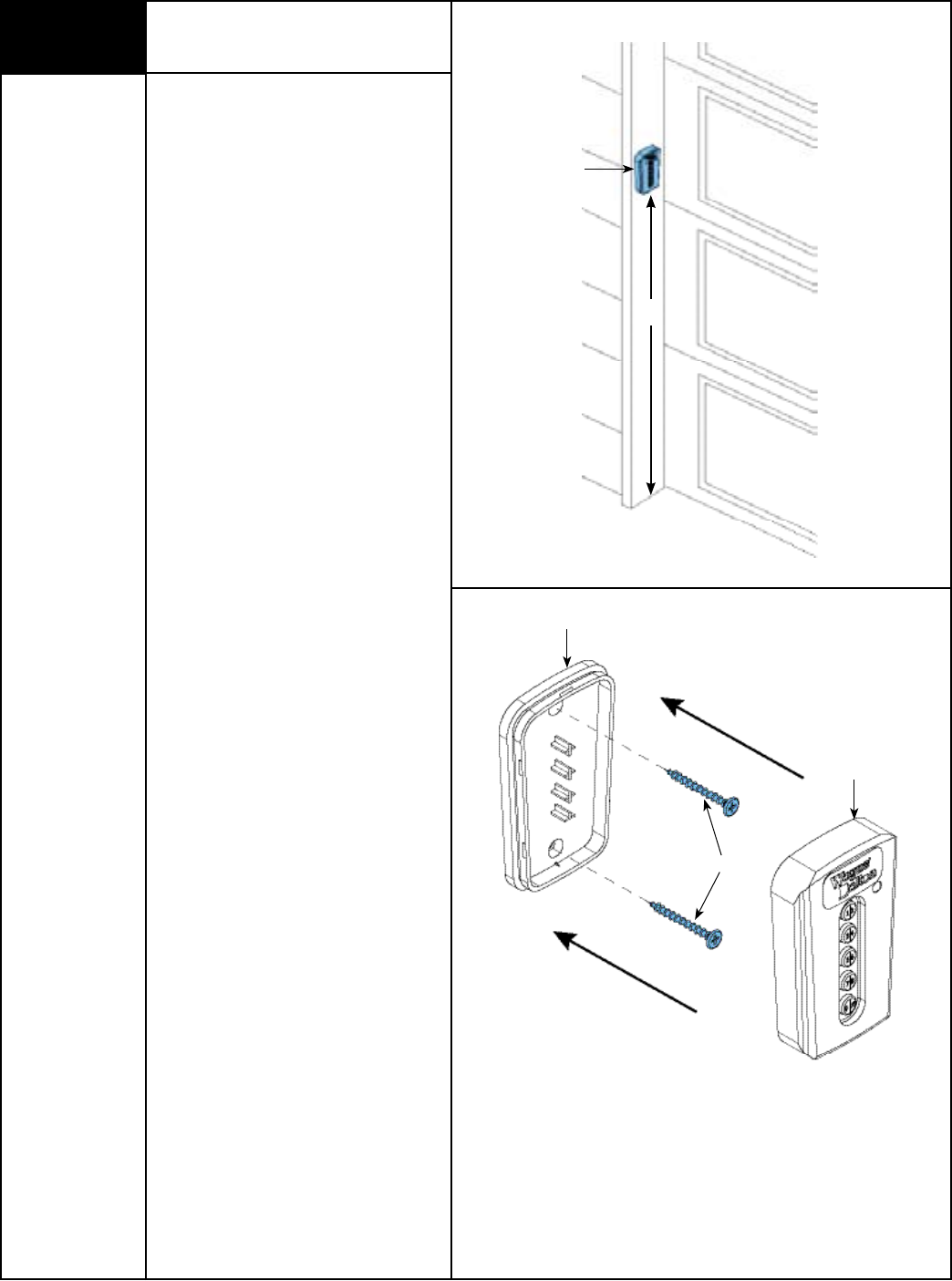
24 Installing Wireless Keyless Entry
(If Included)
Tools Needed:
Power Drill
5/64” Drill Bit
Phillips Head
Screwdriver
IMPORTANT: INSTALL ALL WALL
CONTROLS OUT OF THE REACH OF
CHILDREN AND IN A LOCATION WHERE THE
DOOR CAN BE SEEN BEFORE ACTIVATING.
Locate a convenient place to mount the
wireless keyless entry, that does not
interfere with the normal opening and
closing of the door. To keep keyless entry
out of the reach of children, measure and
mark a spot at least 5 feet up from the floor.
Use the drilling template located on Page 39
to determine hole positions. Drill 5/64” pilot
holes 3/4” deep at each screw location.
Snap open the wireless keyless entry case
with a coin. Secure keyless entry base into
wood framing using the two screws
provided. Snap the front case half back onto
the base. Remove paper backing from
instruction label and apply to a clean
surface inside garage.
NOTE: Two screws are included for
mounting to wood structures. Ensure proper
hardware is used for mounting to other
materials.
NOTE: After completing this step, continue
with page 27.
5’
Screws
Keyless Entry
Keyless Entry Base
Keyless Entry Front
Case
Please Do Not Return This Product To The Store. Call Us Directly! Our Trained Technicians Will Answer Your Questions and/or Ship Any Parts You May Need
You can reach us Toll Free at 1-888-827-3667 for Consumer Assistance or online at www.wayne-dalton.com
20
Power Connection
(Permanent Wiring Option)
Tools Needed:
Needle Nose Pliers
Pliers/Wire Cutters
Flat Tip
Screwdriver
TO AVOID ELECTRICAL SHOCK,
DISCONNECT POWER AT THE FUSE/
BREAKER BOX BEFORE PROCEEDING.
IMPORTANT: CHECK YOUR LOCAL
ELECTRICAL CODES. IF YOUR LOCAL CODE
REQUIRES PERMANENT WIRING, USE THE
SPECIFICATIONS CALLED FOR AND
INSTRUCTIONS ILLUSTRATED.
Permanent Wiring Procedure
1. Ensure power cord is disconnected from
electrical power.
2. Cut power cord 1/2” – 1” from strain
relief/bushing.
3. Use needle nose pliers to remove strain
relief bushing from frame. Squeeze tabs in
on underside of bushing and work bushing
out of hole.
4. Pull or strip off remaining section of outer
insulation from power cord.
5. Remove lens by pressing up on both sides
of the bottom of the lens at the junction of
the housing, releasing the locking tabs,
and pulling forward; remove light bulb (if
installed).
6. Remove the housing from the chassis by
removing the screw securing the
housing to the chassis. Press on the
locking tabs and slide the cover off the
chassis.
7. Pull the three wires into the opener;
strip 1/2” of insulation from the black,
white, and green wires.
8. Using wire nuts for 14-18 AWG wire,
connect the black wire to black wire, the
white wire to white wire and the green
wire to green wire. Make sure connections
are secure.
9. Replace opener cover.
Reconnect the power at the fuse/ breaker
box, as soon as power is applied to the unit,
the light on the opener will blink once to
indicate a successful self check of the
controls.
WARNING
Live & Neutral
Ground
Opener
1/2” To 1”
Power Cord
Strain Relief Bushing
Strain Relief
Bushing
Screw
Lens
Light Bulb
Tabs
Tab
Chassis
Tabs
Housing
Wire Nuts
Please Do Not Return This Product To The Store. Call Us Directly! Our Trained Technicians Will Answer Your Questions and/or Ship Any Parts You May Need
You can reach us Toll Free at 1-888-827-3667 for Consumer Assistance or online at www.wayne-dalton.com
21
U-BAR
Door Bracket
Male Part Of Top
Section
Door Bracket
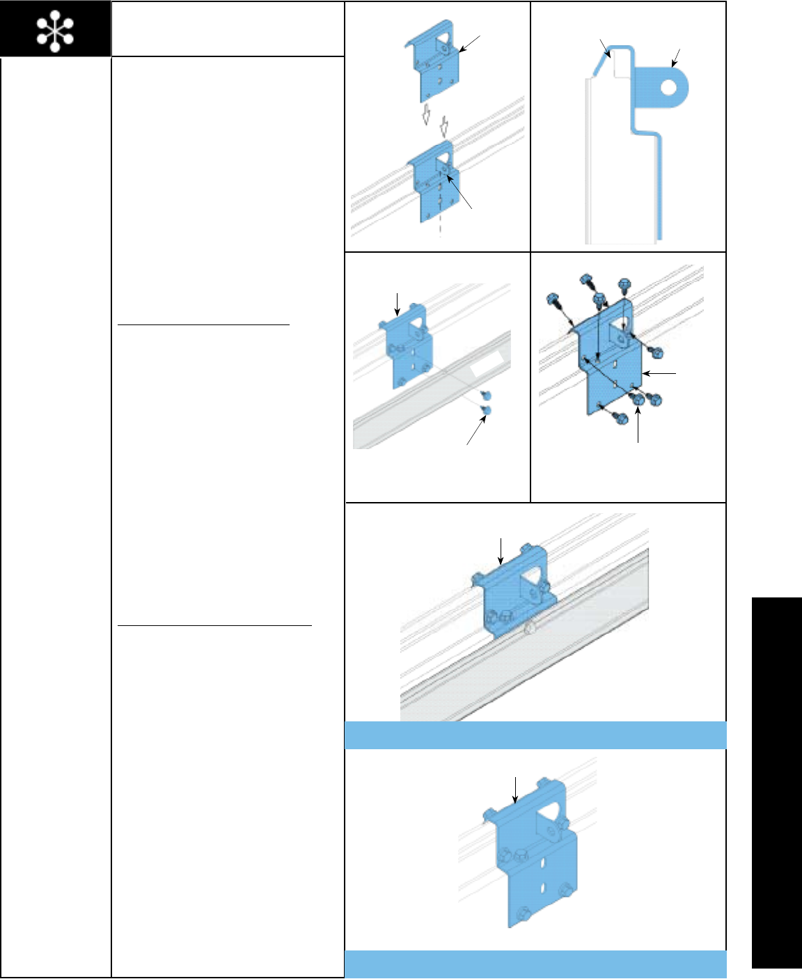
Align Tab With Center
Line Of Top Section
Or Ubar
Mounting Door Bracket To
A 9700 Series Door
IMPORTANT: WHEN CONNECTING A
TROLLEY TYPE GARAGE DOOR OPENER
TO A 9700 SERIES DOOR, A WAYNE-
DALTON OPENER/TROLLEY BRACKET
MUST BE SECURELY ATTACHED TO THE
TOP SECTION OF THE DOOR, ALONG WITH
ANY U-BARS PROVIDED WITH THE DOOR.
THE INSTALLATION OF THE OPENER MUST
BE ACCORDING TO MANUFACTURER’S
INSTRUCTIONS AND FORCE SETTINGS
MUST BE ADJUSTED PROPERLY.
Locate the center of the top section or
factory attached u-bar as shown in FIG 1.1.
FOR TOP SECTION WITH U-BAR:
Remove and retain 4-6 screws from the
center of the u-bar, allowing the door
bracket to slide between the section and the
u-bar.
Position the door bracket until it seats on
the male part of the section as shown in FIG
1.2. The door bracket must be centered and
positioned on the top section so it bridges
the transition point of the section thickness.
Attach the door bracket using
1/4” - 14 x 5/8” self tapping screws as
shown in FIG 1.4. Re-attach the u-bar using
(2) 1/4” - 20 x 11/16” self drilling screws
through the door bracket as shown in
FIG 1.3. Finish re-attaching the u-bar using
the self tapping screws removed previously.
FOR TOP SECTION WITHOUT U-BAR:
Position the door bracket until it seats on
the male part of the section as shown in FIG
1.2. The door bracket must be centered and
positioned on the top section so it bridges
the transition point of the section thickness.
Attach the door bracket using
1/4” - 14 x 5/8” self tapping screws as
shown in FIG 1.4.
NOTE: After completing this step, continue
with Step 7.
Tools Needed:
Power Drill
7/16” Socket
Driver
Door Bracket
(2) 1/4”-20 x 11/16”
Self Drilling Screws
(8) 1/4”-14 x 5/8”
Self Tapping Screws
Door Bracket
Door Bracket
Top Section With U-Bar
Top Section Without U-Bar
Door Bracket
FIG. 1.1 FIG. 1.2
FIG. 1.3 FIG. 1.4
OPTIONAL INSTALLATIONS
Please Do Not Return This Product To The Store. Call Us Directly! Our Trained Technicians Will Answer Your Questions and/or Ship Any Parts You May Need
You can reach us Toll Free at 1-888-827-3667 for Consumer Assistance or online at www.wayne-dalton.com
22
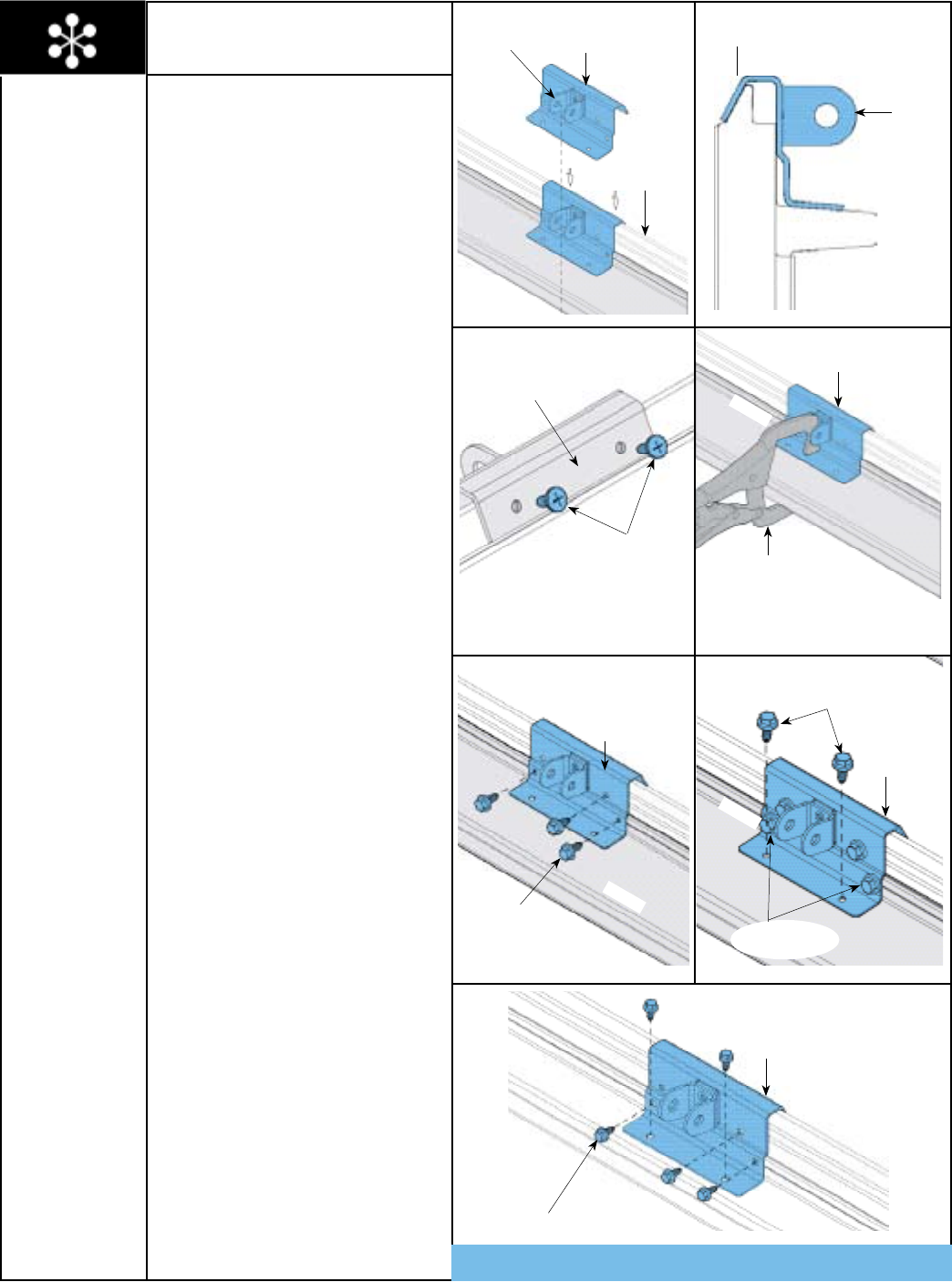
Mounting Door Bracket To A
(9100, 9400, 9600, 5120 & 5140 Series Door)
IMPORTANT: WHEN CONNECTING A
TROLLEY TYPE GARAGE DOOR OPENER
TO THE ABOVE LISTED DOORS, A WAYNE-
DALTON OPENER/TROLLEY BRACKET
MUST BE SECURELY ATTACHED TO THE
TOP SECTION OF THE DOOR, ALONG WITH
ANY U-BARS PROVIDED WITH THE DOOR.
THE INSTALLATION OF THE OPENER MUST
BE ACCORDING TO MANUFACTURER’S
INSTRUCTIONS AND FORCE SETTINGS
MUST BE ADJUSTED PROPERLY.
Locate the center of the top section and seat
the door bracket on male part of the top
section. The door bracket must be centered
and positioned on top section so it bridges
the transition point of the section thickness,
as shown in FIG. 1.1 and 1.2. Install (2) #12
x 1/2” phillips head screws on the opposite
side of door bracket, as shown in FIG. 1.3. If
initially supplied ubar is on the door, clamp
door bracket to u-bar, as shown in FIG. 1.4.
First attach (3) 1/4” - 14 x 5/8” self-tapping
screws to the door bracket, as shown in
FIG. 1.5. Then attach (2) 1/4” - 14 x 5/8”
self-tapping screws to the door bracket, as
shown in FIG. 1.6. Remove vice clamps.
NOTE: If you have a 9100 door, you can use
two of the 1/4” - 20 x 11/16” self-drilling
screws used to attach the u-bar instead of
the 1/4” - 14 x 5/8” self-tapping screws
when attaching door bracket to u-bar, as
shown in FIG. 1.6.
NOTE: When attaching door bracket to top
section with u-bar, apply additional pressure
to thread fasteners into the u-bar.
NOTE: See FIG. 1.7 for installing door
bracket on top section without u-bars.
NOTE: After completing this step, continue
with Step 7.
FIG. 1.1
FIG. 1.3
FIG. 1.5
FIG. 1.2
FIG. 1.4
FIG. 1.6
Tools Needed:
Power Drill
7/16” Socket
Driver
Vice Clamps
Phillips Head
Screwdriver
U-BAR
U-BAR
U-BAR
Door Bracket
Align Tab With Center
Line Of Top Section
Top Section With Or
Without U-Bar
Opposite Side Of
Door Bracket
(2) #12 x 1/2”
Phillips Head Screws
Door Bracket
Vice Clamp
NOTE: Not Required
For J-Struts
(3) 1/4”-14 x 5/8”
Self Tapping Screws
(2) 1/4”-14 x 5/8”
Self Tapping Screws
(2) 1/4”-20 x 11/16”
Self Drilling Screws
Door Bracket
Door Bracket
Door Bracket
(5) 1/4”-14 x 5/8”
Self Tapping Screws
Male Part Of Top
Section
Door Bracket
Fig. 1.7 Top Section Without U-Bar
Please Do Not Return This Product To The Store. Call Us Directly! Our Trained Technicians Will Answer Your Questions and/or Ship Any Parts You May Need
You can reach us Toll Free at 1-888-827-3667 for Consumer Assistance or online at www.wayne-dalton.com
23
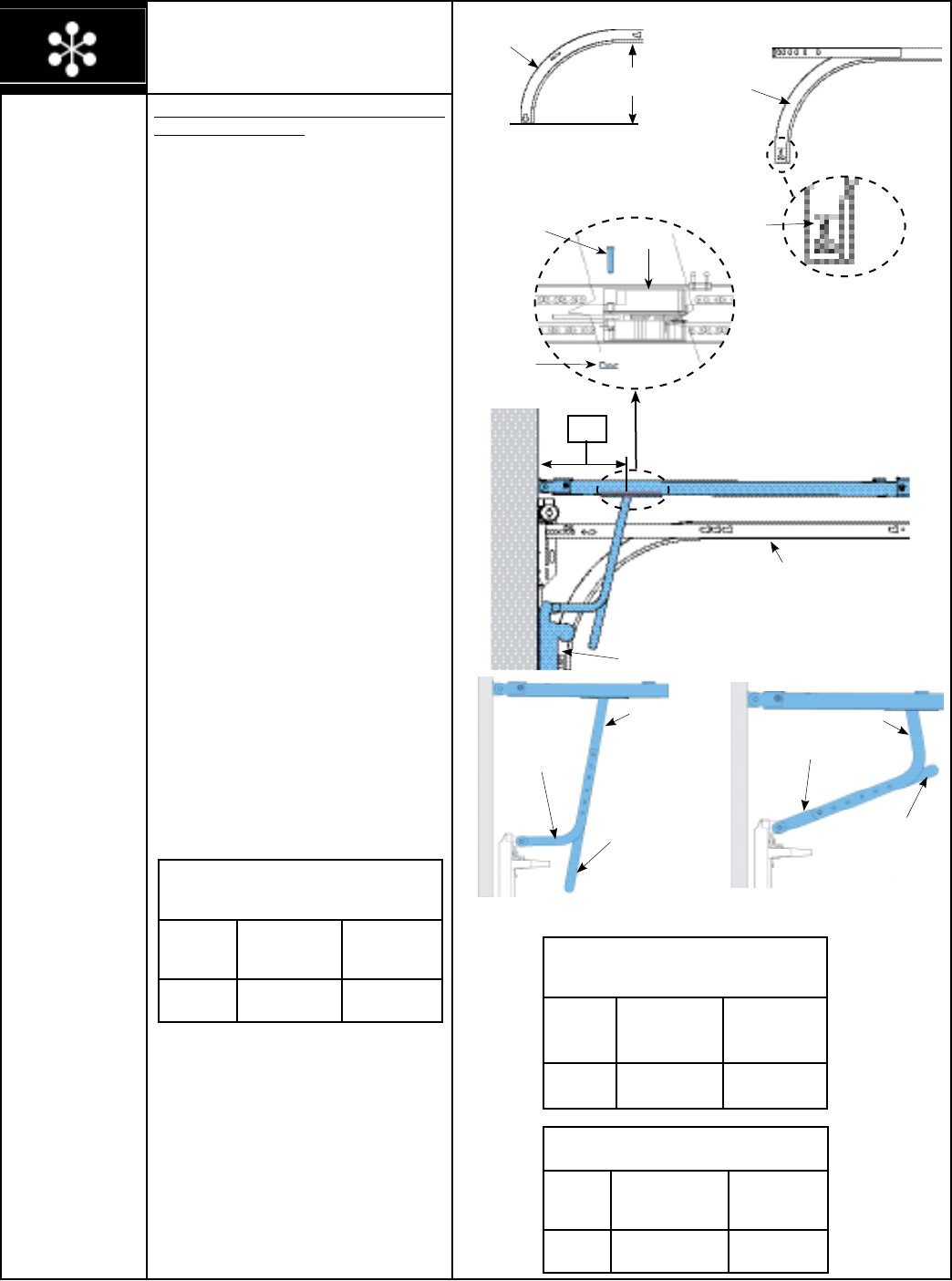
DETERMINE THE WAYNE-DALTON TRACK
RADIUS BEING USED:
FOR MOUNT HOPE AND PENSACOLA
TRACK:
Measure the curved ends of the horizontal
track to determine if you have a 12” or 15”
radius horizontal track, as shown in FIG. 1.
FOR PORTLAND TRACK:
The horizontal tracks are stamped with
radius on the side of the horizontal track, as
shown in FIG. 1.1.
NOTE: If necessary, remove the upper arm
(straight arm) from the trolley, to use the
lower arm (curved arm). Remove the hairpin
cotter from the clevis pin at the front of
trolley and slide clevis pin out far enough
to slide the upper arm out between the left
and right side of trolley body. Position the
lower door arm so the end with the single
hole lines up with the clevis pin. Slide clevis
pin completely back into trolley and reinstall
hairpin cotter.
LOW HEADROOM:
If you have low headroom track, as shown
in FIG. 1.6 on page 24, then proceed with
“Low Headroom Trolley Positioning Charts”
on page 24.
STANDARD LIFT:
Using the STANDARD LIFT TROLLEY
POSITIONING CHARTS, refer to DIM “X” to
set the distance from header to trolley, as
shown in FIG. 1.2.
NOTE: Depending on your setup, you may
have to cut straight arm to accomplish trolley
settings.
If adjustment of the trolley position is
required, use the close travel adjustment
screw located on the bottom of the opener,
as shown in FIG 1.5 on page 24. A 1/4 turn
equals approximately 1” of trolley travel; turn
clockwise to decrease distance (forward)
and counter-clockwise to increase distance
(forward).
NOTE: Proceed with “Connecting Door Arm
To Door” Step 18, on page 14.
STANDARD LIFT TROLLEY POSITIONING CHART
FOR (MODEL 9700) 15” RADIUS
DIM “X” TYPE OF ARM
BEING USED
REFERENCE
ILLUSTRATIONS
10 9/16”-
14 5/8”
STRAIGHT /
CURVED FIG. 1.3
Setting Trolley Close Position/
Connecting Door Arm
(Models 9100, 9400, 9600, 5120, 5140 & 9700)
With TorqueMaster® Or Extension Springs
FIG. 1.3
Cut Straight Arm To
Accomplish Trolley
Setting
Curved
Arm
Straight Arm
FIG. 1.4
Straight Arm
Curved Arm
Cut Straight Arm To
Accomplish Trolley
Setting
Stamped
Radius
FIG. 1.1
Horizontal
Track
FIG. 1
Horizontal
Track
12” OR 15”
STANDARD LIFT TROLLEY POSITIONING CHART
FOR (MODELS 9100, 9400, 9600, 5120 & 5140)
10” AND 12” RADIUS
DIM “X” TYPE OF ARM
BEING USED
REFERENCE
ILLUSTRATIONS
11 1/2” CURVED /
STRAIGHT FIG. 1.4
STANDARD LIFT TROLLEY POSITIONING CHART
FOR (MODELS 9100, 9400, 9600, 5120 & 5140)
14” AND 15” RADIUS
DIM “X” TYPE OF ARM
BEING USED
REFERENCE
ILLUSTRATIONS
13”-15” CURVED /
STRAIGHT FIG. 1.4
FIG. 1.2
Top Section
10”, 12”, 14”, OR 15”
Standard Lift Track
“X”
Clevis Pin
Hairpin Cotter
Trolley
TOP vIEw
Tools Needed:
Needle Nose Pliers
Adjustable Wrench
Ratchet Wrench
7/16” Socket
9/16” Socket
Hacksaw
Please Do Not Return This Product To The Store. Call Us Directly! Our Trained Technicians Will Answer Your Questions and/or Ship Any Parts You May Need
You can reach us Toll Free at 1-888-827-3667 for Consumer Assistance or online at www.wayne-dalton.com
24
LOW HEADROOM TROLLEY POSITIONING CHART
FOR (MODEL 9700)
DIM “X” TYPE OF ARM
BEING USED
REFERENCE
ILLUSTRATIONS
14 3/4”-
17 11/16”
CURVED /
STRAIGHT FIG. 1.7
OPTIONAL HOOKUP
10” - 14” STRAIGHT FIG. 1.7a
LOW HEADROOM:
Using the LOW HEADROOM TROLLEY
POSITIONING CHARTS, refer to DIM “X”
to set the distance from header to trolley, as
shown in FIG. 1.6.
NOTE: Depending on your setup, you may or
may not have to cut straight arm to
accomplish trolley settings.
If adjustment of the trolley position is
required, use the close travel adjustment
screw located on the bottom of the opener,
as shown in FIG 1.5. A 1/4 turn equals
approximately 1” of trolley travel; turn
clockwise to decrease distance (forward)
and counter-clockwise to increase distance
(forward).
NOTE: Proceed with “Connecting Door Arm
To Door” Step 18, on page 14.
Setting Trolley Close Position/
Connecting Door Arm
(Continued)
Low Headroom Track
Top
Section
FIG. 1.7
Curved Arm
Cut Straight Arm To
Accomplish Trolley
Setting
“X”
FIG. 1.6
LOW HEADROOM TROLLEY POSITIONING CHART
FOR (MODELS 9100, 9400, 9600, 5120 & 5140)
DIM “X” TYPE OF ARM
BEING USED
REFERENCE
ILLUSTRATIONS
TO THE RIGHT
14 1/2” CURVED /
STRAIGHT FIG. 1.7
OPTIONAL HOOKUP
10” - 14” STRAIGHT FIG. 1.7a
Bottom Of Opener
FIG. 1.5
FIG. 1.7a
Straight Arm
Please Do Not Return This Product To The Store. Call Us Directly! Our Trained Technicians Will Answer Your Questions and/or Ship Any Parts You May Need
You can reach us Toll Free at 1-888-827-3667 for Consumer Assistance or online at www.wayne-dalton.com
25
DETERMINE THE WAYNE-DALTON
TRACK RADIUS BEING USED:
FOR MOUNT HOPE AND PENSACOLA
TRACK:
Measure the curved ends of the horizontal
track to determine if you have a 12” or 15”
radius horizontal track, as shown in FIG. 1.
FOR PORTLAND TRACK:
The horizontal tracks are stamped with
radius on the side of the horizontal track, as
shown in FIG. 1.1.
NOTE: If necessary, remove the upper arm
(straight arm) from the trolley, to use the
lower arm (curved arm). Remove the hairpin
cotter from the clevis pin at the front of
trolley and slide clevis pin out far enough
to slide the upper arm out between the left
and right side of trolley body. Position the
lower door arm so the end with the single
hole lines up with the clevis pin. Slide clevis
pin completely back into trolley and reinstall
hairpin cotter.
LOW HEADROOM:
If you have low headroom track, as shown
in FIG. 1.5 on page 26, then proceed with
“Low Headroom Trolley Positioning Charts”
on page 26.
STANDARD LIFT:
Using the STANDARD LIFT TROLLEY
POSITIONING CHARTS, refer to DIM “X”
to set the distance from header to trolley, as
shown in FIG. 1.2.
NOTE: Depending on your setup, you may
have to cut straight arm to accomplish
trolley settings.
If adjustment of the trolley position is
required, use the close travel adjustment
screw located on the bottom of the opener,
as shown in FIG 1.4 on page 26. A 1/4
turn equals approximately 1” of trolley
travel; turn clockwise to decrease distance
(forward) and counter-clockwise to increase
distance (forward).
NOTE: Proceed with “Connecting Door Arm
To Door” Step 18, on page 14.
Cut Straight Arm To
Accomplish Trolley
Setting
Curved
Arm
Straight Arm
FIG. 1.3
STANDARD LIFT TROLLEY POSITIONING
CHART FOR 10” AND 12” RADIUS
FOR (MODELS 9100, 9400, 9600, 5120 & 5140)
DIM “X” TYPE OF ARM
BEING USED
REFERENCE
ILLUSTRATIONS
11 1/2”-13” STRAIGHT /
CURVED FIG. 1.3
STANDARD LIFT TROLLEY POSITIONING CHART
FOR 14” AND 15” RADIUS
(MODELS 9100, 9400, 9600, 5120 & 5140)
DIM “X” TYPE OF ARM
BEING USED
REFERENCE
ILLUSTRATIONS
10”-12” STRAIGHT /
CURVED FIG. 1.3
STANDARD LIFT TROLLEY POSITIONING CHART
FOR (MODEL 9700) 15” RADIUS
DIM “X” TYPE OF ARM
BEING USED
REFERENCE
ILLUSTRATIONS
11 1/16”-
16 7/8”
STRAIGHT /
CURVED FIG. 1.3
Setting Trolley Close Position/
Connecting Door Arm
(Models 9100, 9400, 9600, 5120, 5140 & 9700)
With Torsion Springs
FIG. 1
Horizontal
Track
12” OR 15”
FIG. 1.2
Top Section
10”, 12”, 14”, OR 15”
Standard Lift Track
“X”
Clevis Pin
Hairpin Cotter
Trolley Stamped
Radius
FIG. 1.1
Horizontal
Track
TOP vIEw
Tools Needed:
Needle Nose Pliers
Adjustable Wrench
Ratchet Wrench
7/16” Socket
9/16” Socket
Hacksaw
Please Do Not Return This Product To The Store. Call Us Directly! Our Trained Technicians Will Answer Your Questions and/or Ship Any Parts You May Need
You can reach us Toll Free at 1-888-827-3667 for Consumer Assistance or online at www.wayne-dalton.com
26
LOW HEADROOM:
Using the LOW HEADROOM TROLLEY
POSITIONING CHART, refer to DIM “X” to
set the distance from header to trolley, as
shown in FIG. 1.5.
NOTE: Depending on your setup, you may or
may not have to cut straight arm to
accomplish trolley settings.
If adjustment of the trolley position is
required, use the close travel adjustment
screw located on the bottom of the opener.
A 1/4 turn equals approximately 1” of trolley
travel; turn clockwise to decrease distance
(forward) and counter-clockwise to increase
distance (forward).
NOTE: Proceed with “Connecting Door Arm
To Door” Step 18, on page 14.
LOW HEADROOM TROLLEY
POSITIONING CHART FOR (MODEL 9700)
DIM “X” TYPE OF ARM
BEING USED
REFERENCE
ILLUSTRATIONS
15”-18” CURVED /
STRAIGHT FIG. 1.6
OPTIONAL HOOKUP
10” - 14” STRAIGHT FIG. 1.6a
FIG. 1.6
Curved Arm
Cut Straight Arm To
Accomplish Trolley
Setting
Low Headroom Track
“X”
FIG. 1.5
LOW HEADROOM TROLLEY
POSITIONING CHART FOR
(MODELS 9100, 9400, 9600, 5120 & 5140)
DIM “X” TYPE OF ARM
BEING USED
REFERENCE
ILLUSTRATIONS
20” CURVED /
STRAIGHT FIG. 1.6
OPTIONAL HOOKUP
10” - 14” STRAIGHT FIG. 1.6a
Setting Trolley Close Position/
Connecting Door Arm
(Continued)
Bottom Of Opener
FIG. 1.4
FIG. 1.6a
Straight Arm
Please Do Not Return This Product To The Store. Call Us Directly! Our Trained Technicians Will Answer Your Questions and/or Ship Any Parts You May Need
You can reach us Toll Free at 1-888-827-3667 for Consumer Assistance or online at www.wayne-dalton.com
27
IMPORTANT SAFETY INSTRUCTIONS
TO REDUCE THE RISK OF SEVERE
INJURY OR DEATH:
1. READ AND FOLLOW ALL INSTRUCTIONS.
2. Never let children operate or play with the door controls.
Keep remote controls away from children.
3. Always keep a moving door in sight and keep people and objects
away until it is completely closed. NO ONE SHOULD CROSS THE
PATH OF A MOVING DOOR.
4. NEVER GO UNDER A STOPPED, PARTIALLY OPEN DOOR.
5. Test the Door/Opener monthly. The garage door MUST reverse on
contact with a 1-1/2 inch high object (or a 2 x 4 board laid flat) on the
floor. The door MUST also reverse when a 6” high object is placed on
the floor in line with safety sensors. If Door/Opener fails these tests,
have adjustments/repairs made immediately. Failure to make
adjustments/repairs may cause severe or fatal injury.
6. When possible, use the Emergency Disconnect only when the door is
in the closed position. Be very cautious using the Emergency
Disconnect when the door is open. Weak or broken spring(s) may
allow the door to fall rapidly, causing a severe or fatal injury.
7. KEEP THE GARAGE DOOR PROPERLY BALANCED. See the owner’s
manual included with the door. An improperly balanced door could
cause a severe or fatal injury. Have a qualified service person make
repairs to the cables, spring assemblies, and other hardware.
8. SAVE THESE INSTRUCTIONS.
Door activation:
Upon activation by either the wall station Up/Down button, transmitter or
wireless keyless entry, the door will move in the following manner:
1. If open, the door will close. If closed, the door will open.
2. If closing, the door will stop. Next activation will open.
3. If opening, the door will stop. Next activation will close.
4. If an obstruction is contacted or the safety sensor beam is
interrupted while closing, the door will reverse and the light will flash.
5. If an obstruction is encountered while opening, the door will stop
and the light will flash. The next activation will close the door.
6. The Infrared Safety Sensor uses an invisible beam which, when
broken by an obstruction, causes a closing door to reverse, prevents
an open door from closing and causes the light to flash.
ALWAYS KEEP MOVING DOOR IN SIGHT AND KEEP PEOPLE AND
OBJECTS AWAY UNTIL IT IS COMPLETELY CLOSED. TO PREVENT A
SEVERE OR FATAL INJURY, AVOID STANDING IN A OPEN DOOR WAY
OR WALKING THROUGH THE DOORWAY WHILE THE DOOR IS
MOVING.
NEVER LET CHILDREN OPERATE DOOR OR PLAY WITH THE DOOR
CONTROLS. KEEP REMOTE CONTROLS AWAY FROM CHILDREN.
FATAL INJURY COULD RESULT SHOULD A CHILD BECOME TRAPPED
BETWEEN THE DOOR AND FLOOR.
KEEP THE GARAGE DOOR PROPERLY BALANCED. AN IMPROPERLY
BALANCED DOOR COULD CAUSE SEVERE OR FATAL INJURY. HAVE A
QUALIFIED SERVICE PERSON MAKE ADJUSTMENTS/REPAIRS TO
CABLES, SPRING ASSEMBLIES, AND OTHER HARDWARE.
Emergency Disconnect:
THE DOOR SHOULD BE FULLY CLOSED WHEN ACTIVATING THE
EMERGENCY RELEASE DISCONNECT. WEAK OR BROKEN SPRINGS
COULD ALLOW AN OPEN DOOR TO FALL RAPIDLY POSSIBLY
CAUSING SEVERE OR FATAL INJURY.
The opener is equipped with an emergency release recessed trolley type
disconnect system, enabling manual operation of the garage door during
power failure. The trolley is disconnected from the chain by pulling down on
the red release knob, allowing the garage door to be operated manually. Do
not use the manual release knob to pull the door open or closed. The trolley
will automatically reconnect when power is restored and door is activated. If
emergency release is used, close door before operating opener.
NOTE: Outside keylock emergency releases are an available accessory and
are recommended for garages without a service entrance.
HOW THE LIGHT WORKS AND WHAT IT MEANS WHEN IT FLASHES:
1. Overhead light automatically turns on when opener is activated and
remains on for 4 minutes for convenience and safety.
2. The light will flash if opener senses an obstruction in the up or
down direction, to warn you of a problem. It will continue flashing for
1 minute, and then shut off.
If the light begins to flash and the door moves a short distance and then
reverses from a wall station button, transmitter or keyless entry, the external
safety sensor device is activated or defective. To temporarily override safety
sensor device and close door, activate wall station up/down button, keeping
button depressed; opener will begin in down direction. The button must
remain depressed until cycle is completed. If the button is released before
cycle is completed, the door will reverse and come to full up position.
Problems in the safety system should be corrected by a qualified service
person.
NOTE: A fully open door with a blinking light indicates an obstruction or
problems with external safety sensors during close travel. See trouble
shooting section on page 35.
WARNING WARNING
WARNING
WARNING
WARNING
OPERATION
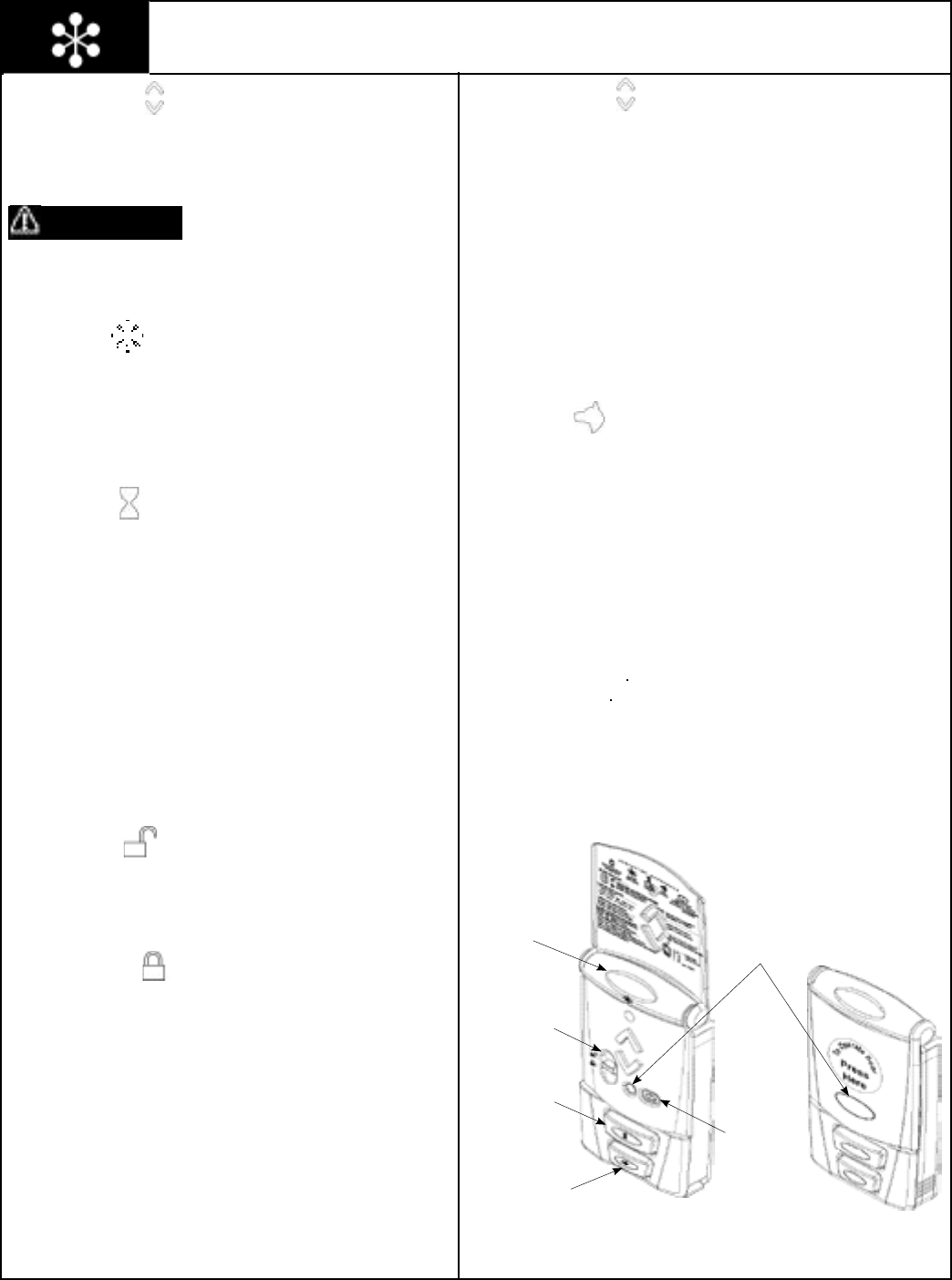
Please Do Not Return This Product To The Store. Call Us Directly! Our Trained Technicians Will Answer Your Questions and/or Ship Any Parts You May Need
You can reach us Toll Free at 1-888-827-3667 for Consumer Assistance or online at www.wayne-dalton.com
28
Up-Down Button:
Momentarily pressing the Up/Down button starts or stops door
movement or changes door’s direction. Pressing and holding Up/
Down button during the door’s travel will override safety sensors. The
Up/Down Button (when unit is closed) can be activated by pressing
flip cover.
IF DOOR REQUIRES THAT SAFETY SENSORS BE OVERRIDDEN
THAT CONDITION MUST BE CORRECTED IMMEDIATELY. FAILURE
TO MAKE ADJUSTMENTS/REPAIRS COULD RESULT IN SEVERE
OR FATAL INJURY.
Light Button:
Momentarily pressing the light button turns on the convenience light.
The light will remain on until either the light button is pressed again
or the door is activated. The light automatically turns on with a door
activation and remains on for 4 minutes. Pressing the light button
before the 4 minutes has elapsed will turn off the light. While the
door is in motion, the light button functions identically as the Up/
Down button, stopping or reversing the door immediately.
Timer Button:
Momentarily pressing the timer button causes a delayed activation of
a stationary fully open door. The light fixture or the opener’s lamp will
blink on and off for about 10 seconds prior to closing the door,
allowing enough time to exit the garage when the opener is in the
timer mode. Pressing any button, except the program button while
the opener lamp is blinking cancels the timer mode.
NOTE: The timer feature will only function with the door in the full
open position. Pressing the timer button with a stationary door in any
other position will cause the opener lamp to blink 4 times and the
door will not be activated.
While the door is in motion, the timer button functions identical to
the Up/Down button, stopping or reversing the door immediately.
Vacation Slide Switch:
The slide switch has two positions: Normal, and Door lock.
Normal position:
Move the slide switch to normal position for all normal functions of
the opener. The normal position will cancel the door lock feature.
NOTE: When the slide switch is moved to the unlocked position the
opener light fixture will blink on/off three times.
Door Lock position:
If the door is stopped (fully open, fully closed or partially open) move
the slide switch to the door lock position to suspend all normal
functions of the opener. The opener will remain completely disabled
and non-operational in this mode. All wall stations, transmitters and
keyless entry units are ignored until the slide switch is moved to the
normal position. If the door is moving when the slide switch is
moved to the door lock position, the door lock mode is not activated
and all functions of the opener remain active.
NOTE: When the slide switch is moved to the locked position the
opener light fixture will blink on/off three times.
Operating the Wireless Wall Station
Back Lit LED Lights:
The Up/Down arrows’ backlit red LED blink intermittently to help you
locate the wall station in a dark garage. This blink rate can be changed
for longer battery life or can be turned off. The default blink rate is one
blink every 2 seconds. For longer battery life the blink rate can be
changed to blink once every 5 seconds. To change the blink rate, remove
the battery cover and remove one battery. Re-install the battery and
within 2 seconds, press the Light button. Re-install the battery cover.
For longest battery life, the blink can be turned off. To turn off the blink,
remove the battery cover and remove one battery.
Re-install the battery and within 2 seconds, press the Pet button. Re-
install the battery cover.
NOTE: The wall station’s arrow LED will light while any wall station
button remains pressed.
Pet Position:
Pressing the pet button opens a closed door to a preset position between
8 and 30 inches above the floor, allowing pets to enter and exit the
garage without the door being fully open. The door must be fully closed
to activate the pet open feature. Pressing the pet button with a stationary
door in the pet open position will cause the door to close. Pressing the
Up/Down button while the door is in the pet position will cause the door
to open. While the door is in motion, the pet button functions identically
to the Up/Down button, stopping or reversing the door immediately. The
pet feature allows for custom setting of the pet position door height.
NOTE: A door in the “pet position” (open 8-30 inches) is not locked and
should not be used as a secured door position.
Program Button:
The wall station program button has several functions.
a. It can be used to set a custom pet position. (see Customizing the
Settings, on the next page)
b. It can be used to set the opener’s closing force (see Adjustment
#1 Page 32).
Pet Button
Light Button Up/Down Button
Timer Button
WARNING
Program Button
Vacation
Slide Switch
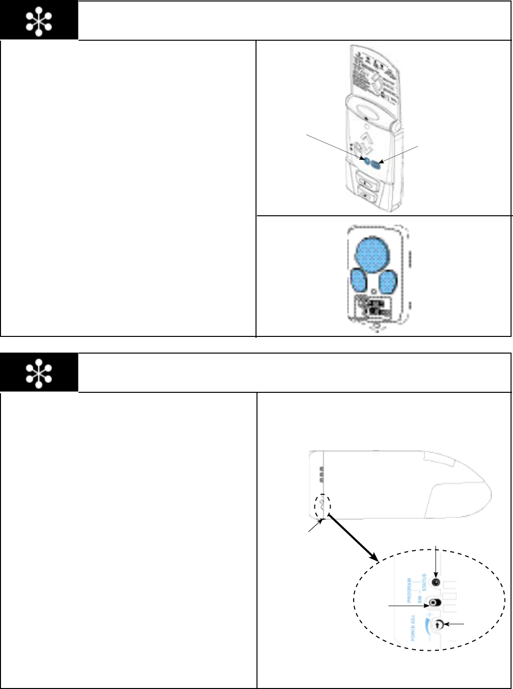
Please Do Not Return This Product To The Store. Call Us Directly! Our Trained Technicians Will Answer Your Questions and/or Ship Any Parts You May Need
You can reach us Toll Free at 1-888-827-3667 for Consumer Assistance or online at www.wayne-dalton.com
29
Customizing the Settings
Custom pet position:
The pet button opens a closed door to a preset position between 8 and
30 inches above the floor, allowing pets to enter and exit the garage
without the door being fully open. To change the automatic pet opening
height:
Start with the door in the closed position.
1. Operate the door then stop it at the desired height. If desired
height is not achieved, the door must be returned to the closed
position.
2. Press and release the wall stations program button, or the
opener program switch button two times. The status light on the
opener unit and the overhead light will flash on and off at a
normal rate.
3. Press the pet button. The status light on the opener and the
overhead light will flash on and off three times indicating
successful programming.
Multi-Door Programming:
Momentarily pressing the button programmed in the transmitter
programming step activates the door. Other buttons can also be
programmed to activate different doors, for multi-door installations.
Each button or a combination of two buttons pressed simultaneously
can be programmed to activate a different door. Only one button at a
time can be programmed to activate a specific opener. The transmitter
LED will light while any transmitter button remains pressed.
Program Button
Up/Down Button
Opener Controls
Program Status
LED
Program
Button
Right Side Of Opener
The program button located on the right side of the opener has several
functions.
1. Pressing the program button once, will make the status
light and overhead lamp turn on steady. This mode allows
programming of transmitters, wireless keyless entry, and wireless
wall stations (see page 33).
2. Pressing the program button two times will make the
status light and overhead lamp blink on and off. This mode allows
programming of a custom pet position (see “Customizing The
Settings” above).
3. Pressing the program button three times will make the
status light and overhead lamp blink on and off with a long pause
at each blink cycle. This mode allows programming of the opening
force (see page 32).
4. Pressing and holding the program button for 10 seconds
will erase all transmitters, multi-function wall station and wireless
keyless entry from memory. The status light and over
head light will blink 3 times indicating a successful erase operation.
Closing
Force
Bottom Of Opener

Please Do Not Return This Product To The Store. Call Us Directly! Our Trained Technicians Will Answer Your Questions and/or Ship Any Parts You May Need
You can reach us Toll Free at 1-888-827-3667 for Consumer Assistance or online at www.wayne-dalton.com
30
Primary Programming for HomeLink® to the Prodrive™
NOTE: This step can only be done on automobiles equipped with the
HomeLink® System.
NOTE: Programming HomeLink® requires a Wayne-Dalton
Transmitter that is programmed to the opener (the wallstation and
transmitter(s) supplied with the opener, come pre-programmed from
the factory). Any additional wallstation(s) or transmitter(s) will need to
be programmed to the opener, see page 33.
IMPORTANT: Use the programming instructions provided with your
vehicle first. Follow these instructions if the HomeLink® unit does not
learn the transmitter, when using the vehicle’s instructions.
NOTE: If Primary Programming does not work then use the Alternate
Procedure on next page.
NOTE: Vehicle may need to be in accessory position when
programming. Check car owner’s manual.
NOTE: HomeLink® is a registered trademark of Johnson Controls.
Programming/Training HomeLink® Unit
GARAGE DOOR MAY OPERATE DURING PROGRAMMING. TO AVOID
POSSIBLE SEVERE OR FATAL INJURY, PLACE THE EMERGENCY
DISCONNECT HANDLE IN THE MANUAL OPERATED POSITION.
1. Pull the manual disconnect to put the opener in the disengaged
position.
2. Verify the HomeLink® unit has an empty channel press the desired
HomeLink® button and observe the indicator light if it flashes slowly,
the channel is empty and ready for programming. If pressing the
desired channel/button causes the indicator light to blink rapidly, or
come on without blinking this channel is already programmed. You
either need to choose a different channel/button on the HomeLink®, or
perform Step 3 below.
3. OPTIONAL – To completely clear all channels on the HomeLink®
unit, press and hold the two outside buttons on the HomeLink® unit
until the HomeLink® indicator light begins to flash rapidly (approx. 20
seconds), then release both buttons. (Do not perform this step to train
additional hand-held transmitters.) NOTE: This operation erases all
previously learned transmitters and you will need to re-teach any other
transmitters to your HomeLink® unit.
4. Hold the end of the Wayne-Dalton hand-held transmitter
approximately 1 to 3 inches away from the HomeLink® surface keeping
the HomeLink® indicator light in view.
5. Press and hold the desired HomeLink® channel/button indicator light
should flash slowly (indicating empty channel). Continue holding the
HomeLink® button, and press and hold the large button (“U” Models) or
desired button (“A”, “C” or “R” models) on the Wayne-Dalton
transmitter for approximately 3-5 seconds. The HomeLink® indicator
light should now blink rapidly, indicating a successful learn operation.
Release both buttons. Verify transmitter has been learned by pressing
the HomeLink® button used to learn the transmitter; HomeLink®
indicator light will come on without flashing or flash rapidly indicating a
successful learn. Proceed to step 6 below. NOTE: If this procedure is
unsuccessful perform Alternate procedure.
Teaching HomeLink® to the opener
6. Press and release the program switch on the opener. The red
program status light on the opener and light will turn on and remain lit
for one minute, indicating that it is ready to learn.
7. Press the HomeLink® button used in Step 5 above for 1 to 3
seconds. The program status light and convenience light on the opener
will turn on and off three times indicating a successful learn.
8. Press the HomeLink® button once more to operate the door. The
opener will activate and the trolley will travel towards open, the next
activation will cause the trolley to travel to the closed position and
reengage, subsequent operations will move the door.
WARNING

Please Do Not Return This Product To The Store. Call Us Directly! Our Trained Technicians Will Answer Your Questions and/or Ship Any Parts You May Need
You can reach us Toll Free at 1-888-827-3667 for Consumer Assistance or online at www.wayne-dalton.com
31
Alternate Programming for HomeLink® to the Prodrive™
NOTE: This Step can only be done on automobiles equipped with the
HomeLink® System.
NOTE: Programming HomeLink® requires a Wayne-Dalton
Transmitter that is programmed to the opener (the wallstation and
transmitter(s) supplied with the opener, come pre-programmed from
the factory). Any additional wallstation(s) or transmitter(s) will need to
be programmed to the opener, see page 33.
IMPORTANT: Use the programming instructions provided with your
vehicle first. Follow these instructions if the HomeLink® unit does not
learn the transmitter, when using the vehicle’s instructions.
NOTE: Vehicle may need to be in accessory position when
programming. Check car owner’s manual.
NOTE: HomeLink® is a registered trademark of Johnson Controls.
Programming/Training HomeLink® Unit
GARAGE DOOR MAY OPERATE DURING PROGRAMMING. TO AVOID
POSSIBLE SEVERE OR FATAL INJURY, PLACE THE EMERGENCY
DISCONNECT HANDLE IN THE MANUAL OPERATED POSITION.
1. Pull the manual disconnect to put the opener in the disengaged
position.
2. Press and hold the two outside buttons on the HomeLink® unit until
the HomeLink® indicator light begins to flash rapidly (approx. 20
seconds), then release both buttons. (Do not perform this step to train
additional hand-held transmitters.) NOTE: This operation erases all
previously learned transmitters and that you need to re-teach any other
transmitters to your HomeLink® unit by repeating steps 3 - 6 below.
3. Hold the end of the Wayne-Dalton hand-held transmitter
approximately 1 to 3 inches away from the HomeLink® surface
keeping the HomeLink® indicator light in view.
4. Press and hold the Wayne-Dalton hand-held transmitter’s large
center button. The transmitter’s red indicator light will turn on. After 10
seconds the red indicator light will blink rapidly. Do not release the
button and proceed to the next step.
5. Press the desired HomeLink® button. Do not release either button
until step 6 has been completed. NOTE: It is important to immediately
press the HomeLink® button as soon as the transmitter’s red indicator
light blinks. If the red indicator light subsequently turns on or off ignore
it, this is normal.
6. The HomeLink® indicator light will be blinking during the training
operation. When the HomeLink® indicator light flashes rapidly or turns
off (approx. 5 to 60 seconds), both buttons may be released. The
HomeLink® indicator light flashing rapidly or turning off indicates
successful programming of the new frequency signal. Verify transmitter
has been learned by pressing the HomeLink® button used to learn the
transmitter; HomeLink® indicator light will come on without flashing or
flash rapidly indicating a successful learn.
Teaching HomeLink® to the opener
7. Press the program switch on the opener. The red program status
light on the opener and light will turn on and remain lit for one minute,
indicating that it is ready to learn.
8. Press the HomeLink® button used in Step 5 above for 1 to 3
seconds. The program status light on the opener will turn on and off
three times indicating a successful learn.
9. Press the HomeLink® the opener will activate and the trolley will
travel towards open, the next activation will cause the trolley to travel to
the closed position and reengage, subsequent operations will move the
door.
WARNING
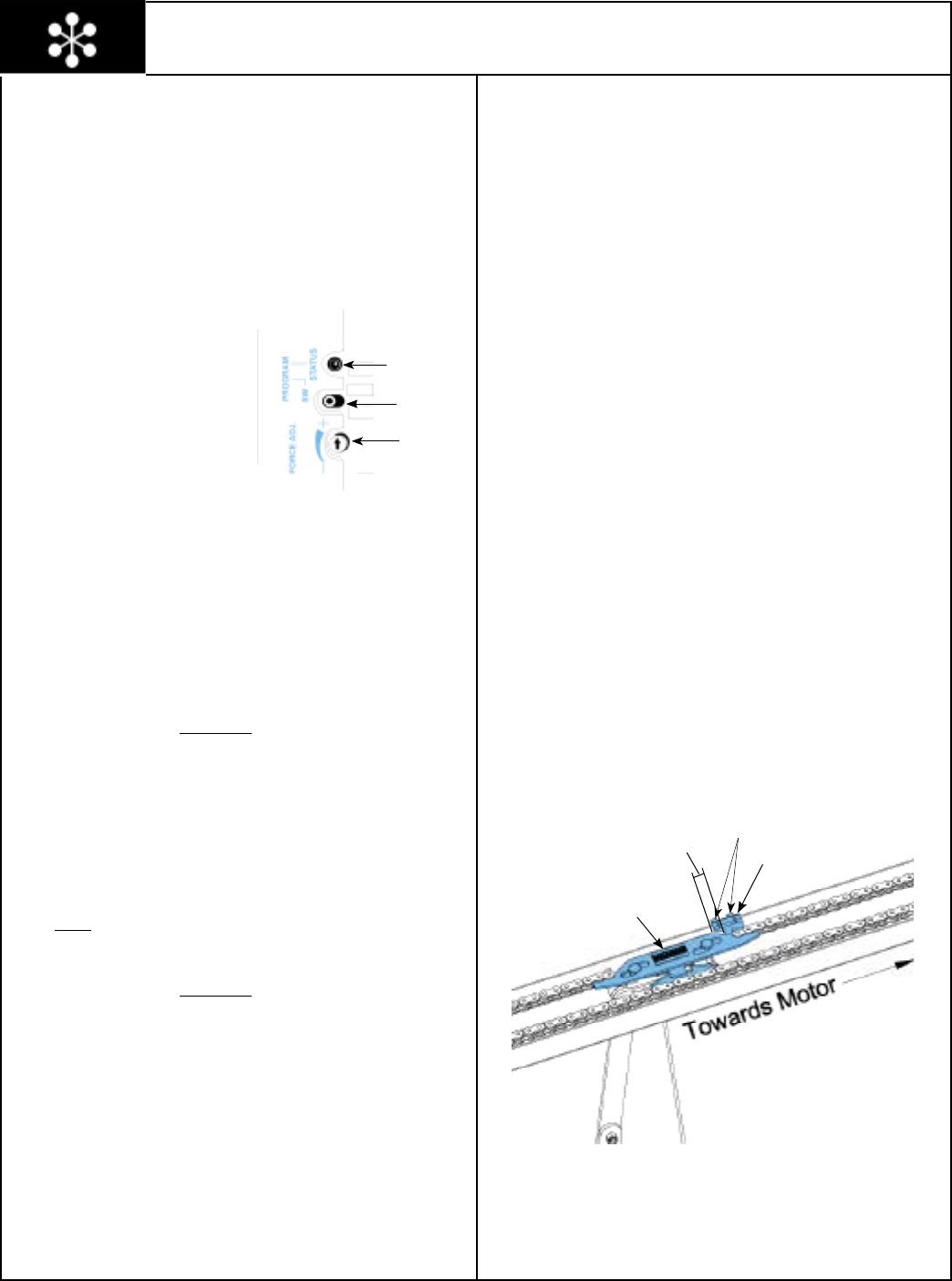
Please Do Not Return This Product To The Store. Call Us Directly! Our Trained Technicians Will Answer Your Questions and/or Ship Any Parts You May Need
You can reach us Toll Free at 1-888-827-3667 for Consumer Assistance or online at www.wayne-dalton.com
32
Adjustments
Adjustment # 1 Opening and Closing Force
This garage door opener is built with a safety system that allows the
door to reverse when closing and stop when opening. This must be
adjusted so your opener does not use excessive force in the down
direction or react to the weight of the door during upward travel.
CLOSING FORCE ADJUSTMENT
To help determine that the closing door force is not excessive, grasp
the door handle or bottom edge during downward travel. The opener
should REVERSE to this force.
NOTE: Do not stand under door
during this test.
To adjust the closing force follow
one of the two methods listed
below.
Method A (manual)
1. Turn the FORCE ADJ. counter
clockwise to decrease force and repeat
reversal test until door reacts properly.
Method B (computer assisted)
1. Operate the door to the fully open position.
2. Turn the FORCE ADJ. counter clockwise to the minimal force setting.
3. Press the PROGRAM button two times or the PROGRAM
button on the Wireless Wall Station (if included) until the LED turns
on solid (5 sec.). The STATUS LED and the overhead lamp will flash
on and off at a slow rate.
4. Operate the door to the fully closed position.
5. Turn the FORCE ADJ. clockwise until the STATUS LED flickers or just
turns off.
6. Press the PROGRAM button once to confirm setting.
OPENING FORCE ADJUSTMENT
To determine that the opening force is not excessive, grasp the door
handle or bottom edge during upward travel. If the opener does not
stop or is hard to hold, decrease the open force setting. The opener
should STOP without using excessive force.
To change the opening force follow the procedure listed below.
1. Operate the door to the fully closed position.
2. Press the PROGRAM button three times. The STATUS LED
and the overhead lamp will flash on and off. The blink rate, which
corresponds to the force setting, will consist of 1 to 5 fast blinks
followed with a long pause between blink sequences.
3. The first time an attempt is made to increase the force, the setting
will begin at the lightest setting (1 blink).
4. To increase the force, press and release the door up/down button on
any control (The STATUS LED will remain lit during button press).
5. Continue to press and release the door button until the desired force
setting is achieved.
6. Press the PROGRAM button once to confirm setting.
Adjustment # 2 Contact Obstruction Sensing
(Closing Direction)
The opener is designed to automatically reverse the door during
closing travel whenever it comes in contact with a 2 x 4 laid flat on
the floor. An object on the floor with a height less than 1-1/2” will not
cause the door to reverse. (Test according to instructions in Step 21.)
If opener reverses properly with a 2 x 4 laid flat on the garage floor
(Step 21) and stops without the solid test object in the fully closed
position, proceed to Adjustment # 3.
When door comes in contact with a 2 x 4 laid flat on the garage floor
and stops instead of reversing, reset the door close limits according to
instruction in Step 19, adjusting until door reverses upon contact with a
2 x 4 laid flat on the garage floor.
If door reverses when it comes in contact with the floor, reset the door
close limits according to instruction in Step 19.
Adjustment # 3 Positive Mechanical Door Lock
The garage door opener is designed with an automatic mechanical
locking system. This lock secures the door in the fully closed
position.
To adjust, activate the door opener and allow the door to go to its fully
closed position. Loosen the two screws on the rail stop and move it
behind the latch assembly with a gap of 3/4” between “stop” and
“latch”. Retighten screws.
“LATCH”
3/4” Rail “Stop”
Program Status
LED
Program
Button
Closing Force
Adjustment
Screws
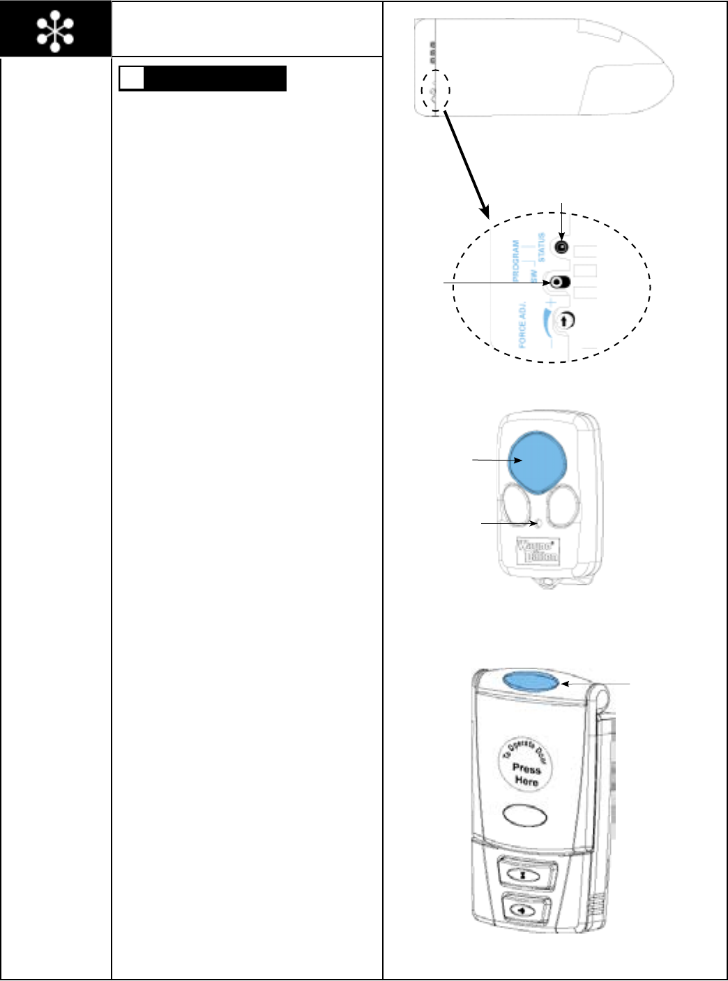
Please Do Not Return This Product To The Store. Call Us Directly! Our Trained Technicians Will Answer Your Questions and/or Ship Any Parts You May Need
You can reach us Toll Free at 1-888-827-3667 for Consumer Assistance or online at www.wayne-dalton.com
33
DURING PROGRAMMING THE GARAGE DOOR
MAY OPERATE. KEEP PEOPLE AND OBJECTS
CLEAR OF THE MOVING DOOR TO PREVENT
DOOR DAMAGE OR POSSIBLE PERSONAL
INJURY.
NOTE: Programming failure can occur if the wall
station or transmitter is too close to the opener during
the programming sequence. There must be a
minimum of 6 feet between the wall station/
transmitter and the opener.
NOTE: The opener can be activated by up to 8 remote
transmitters, 2 wall stations and 2 keyless entries. If a
9th remote is programmed the first remote
programmed will be lost from memory. The same is
true if a third wall station or a third keyless entry is
programmed, the first will no longer be in memory
and will not operate the opener.
NOTE: Do not press any button on the wall station
or transmitter until instructed.
TRANSMITTER:
1. Press and release the PROGRAM button located
on the garage door opener. The red PROGRAM
STATUS light on the opener unit and the overhead
lamp will turn on and remain lit for one minute,
indicating activation of the learn mode.
2. Press one of the buttons on the transmitter you
wish to use to operate the door. The PROGRAM
STATUS light on the opener will turn on and off
three times indicating a successful learn.
3. Press the same button on the transmitter once
more to confirm operation. The opener will turn on
and move the door.
At this point you will be able to activate the opener.
WALL STATION:
1. Press and release the PROGRAM button located
on the garage door opener. The red PROGRAM
STATUS light on the opener unit and the overhead
lamp will turn on and remain lit for one minute,
indicating activation of the learn mode.
2. Press the light on/off button on the wall station.
The program status light will turn on and off three
times indicating a successful learn.
3. Press the light on/off button on the wall station
once more to confirm operation. The overhead light
will toggle from on to off and from off to on.
At this point you will be able to activate the opener.
Program Status
LED
Program
Button
Programming Wireless Wall Station(s)
Or Transmitter(s) to Opener
Tools Needed:
None
Right Side Of Opener
WARNING
Light
Button
Wall Station
Large Button
LED
Transmitter

Please Do Not Return This Product To The Store. Call Us Directly! Our Trained Technicians Will Answer Your Questions and/or Ship Any Parts You May Need
You can reach us Toll Free at 1-888-827-3667 for Consumer Assistance or online at www.wayne-dalton.com
34
Maintenance
Monthly Maintenance:
1. Lubricate hinges and rollers of garage door.
2. Inspect the door for loose fasteners, worn or frayed counterbalance
cables and the presences of legible safety labels/ tags. Have repairs
made by a qualified service person. Contact customer assistance
for free replacement safety labels/ tags.
3. With door fully closed, pull down on the emergency disconnect to
manually operate the door. If the door feels unbalanced or binds,
have a qualified service person make necessary adjustments or
repairs to the door.
4. Perform the contact/obstruction tests. See Steps 21 and 22 for the
contact/obstruction test instructions. If door/opener fails contact/
obstruction test reset the door close limits according to the
instructions in Step 19, adjusting until door reverse on contact with
a 2 x 4 board laid flat on the garage floor. If opener still fails, have a
qualified service person make adjustments/repairs or this could
result in severe or fatal injury.
5. Failure of door/opener to respond to transmitter, multi-function wall
station or wireless keyless entry may be due to a weak or dead
battery. Press and hold the activation button on either the
transmitter or the wall station. If the LED does not light, this is an
indication that the battery is weak or dead. Replace the battery.
Twice a Year:
Check chain tension. If chain rests on bottom of rail, adjust tension by
turning the two chain adjusting nuts at the end of the rails
(opposite the opener end) clockwise. Make sure to adjust both nuts
equal amounts and until chain is approximately 1/2” above the bottom
of rails when measured in the middle of the rails.
Battery Replacement for Wall Station:
Remove the battery cover completely (right-hand side of wall station)
by disengaging the battery cover’s lower clip; remove the remove the
old batteries. Install two AAA batteries into the wall station observing
the polarity, (+) and (-), of both batteries. After a few seconds, the up/
down red LED will begin to blink every two seconds. If it is desired to
slow the LED blink rate refer to the wall station operation section on
page 28 “Backlit LED Lights”. Re-install the battery cover by first
inserting its top into the wall station then inserting and securing its
bottom.
Note: Use only two AAA batteries.
Note: Dispose of dead batteries properly.
Battery Replacement for Transmitter:
Insert a coin in the coin slot of the transmitter and twist coin to access
the dead battery. Replace the batteries, being careful to match the
positive (+) symbols on the circuit boards with the battery; snap case
back together.
Note: Transmitters use two CR2016 or equivalent batteries.
Note: Dispose of dead batteries properly.
Battery Replacement for Wireless Keyless Entry:
To change batteries, snap open case with a coin and remove old
batteries. Replace the batteries, being careful to match the positive
(+) symbols on the circuit boards with the battery; snap case back
together.
Note: Keyless entries use two CR2032 or equivalent batteries.
Note: Dispose of dead batteries properly.

Please Do Not Return This Product To The Store. Call Us Directly! Our Trained Technicians Will Answer Your Questions and/or Ship Any Parts You May Need
You can reach us Toll Free at 1-888-827-3667 for Consumer Assistance or online at www.wayne-dalton.com
35
SYMPTOM PROBABLE CAUSE CORRECTIVE ACTION
Opener won’t work from wall button or radio control. No power to opener.
Short circuit in wires to opener or wall button.
Motor Protector trips open due to excessive use.
Check cord to outlet, wall switch and circuit breaker.
Isolate by disconnecting the wires at the opener from the wall
station.
Allow motor to cool for 20 minutes and try again.
Opener works from wall button but not from radio control. Radio control system non-operational. Weak or dead battery in transmitter replace.
Security code not matched between receiver and transmitter
(see page 33)
If two or more transmitters don’t work, have motor control board
tested.
Door does not open and opener light flashes. Something obstructing door travel.
Insufficient opening force.
Build up of ice and snow around door.
Disconnect door from operator. Operate door by hand to locate
obstruction or call a service person.
Adjust opening force. (See Adj. #1 on page 32).
Shovel and clear door area.
Door does not open fully and light does not flash. Open limit not set properly. Adjust open travel with screwdriver, turn counter-clockwise to
desired setting. 1/4 turn equals to 1” of travel (see Step 20).
Door stops and does not close fully. Close limit not set properly. Adjust close travel with screwdriver, turn clockwise to desired
setting. 1/4 turn equals 1” of travel (See Step 19).
Door closes and then returns to fully open position and
opener light flashes.
Door arm adjustment.
Close travel adjustment is set beyond normal door position.
Obstructions on floor.
Adjust door arm (See Step 17 and 18).
Adjust close travel with screwdriver, turn counter-clockwise to
desired setting. 1/4 turn equals 1” of travel (See Step 19).
Check for stones or ice under door and remove.
When activated with door in fully open position, door travels
for 1 second, stops, and returns to fully open position and
light begins to flash.
Infrared safety sensors out of adjustment or defective.
Obstructions in door opening.
Infrared safety sensors alignment should be checked per
instructions. (See Step 16).
Check for object blocking Infrared safety sensors.
Door reverses travel before reaching fully closed position
and opener light flashes.
Activation of obstruction sensing system.
Loose or hanging objects on door activating Infrared safety
sensor.
Insufficient closing force.
Check for binding in door travel (door “stops”, door tracks, etc).
Remove objects.
Adjust closing force. (See Adj. #1 on page 32).
Door fully opens and then light flashes. Open limit is set too high and trolley is hitting the stop bolt. Adjust open travel with screwdriver, turn clockwise to desired
setting. 1/4 turn equals to 1” of travel (see Step 20).
Troubleshooting
MAINTENANCE/ TROUBLESHOOTING
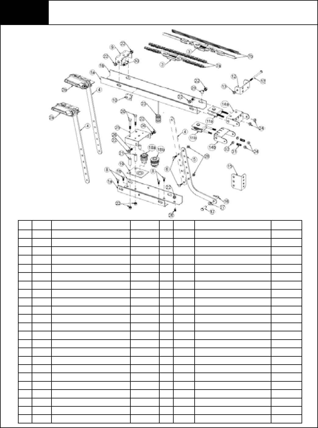
Please Do Not Return This Product To The Store. Call Us Directly! Our Trained Technicians Will Answer Your Questions and/or Ship Any Parts You May Need
You can reach us Toll Free at 1-888-827-3667 for Consumer Assistance or online at www.wayne-dalton.com
36
Parts Breakdown Rail Assembly - All Models
#. Part # Description # Per Unit #. Part # Description # Per Unit
1a. 325756 R.H. Rail (7’) 1 12. 220959 Front Wall Bracket 1
325758 R.H. Rail (8’) 1 13. 157559 1/4” - 20 x 4” Hex Head Bolt w/ Lock Nut 1
325760 R.H. Rail (10’) 1 14a. 220958 Front Bracket - Chain 1
1b. 325753 L.H. Rail (7’) 1 14b. 320696 Front Bracket - Belt 1
325757 L.H. Rail (8’) 1 15. 220956 Door Bracket 1
325759 L.H. Rail (10’) 1 16. 326207 Hairpin Cotter 1
2a. 324527 Trolley Assembly - Chain 1 17. 326206 5/16” x 1-1/4” Multi-Grip Clevis Pin 1
2b. 320697 Trolley Assembly - Belt 1 18a. 325022 Sprocket Coupling w/ Bushing - Chain 1
3. 309960 Chain Latch Assembly 1 18b. 325687 Sprocket Coupling w/ Bushing - Belt 1
4. 324273 Door Arm (Upper) 1 19. 252106 Sprocket Base Assembly 1
5. 324272 Door Arm (Lower) 1 20. 251228 5/16” - 18 x 2” Hex Bolts 2
6. 308967 1/4” - 20 x 3/4” Machine Bolt 2 21. 221014 Spacer Tubes 2
7a. 325682 Chain, 7’ 1 22. 220999 5/16” - 18 KEP Nut As Req.
325683 Chain, 8’ 1 23. 157143 Red Release Knob 1
325684 Chain, 10’ 1 24. 157665 Adjusting Nuts 2
7b. 325685 Belt, 7’ 1 25. 324270 Sprocket Cap Assembly 1
325686 Belt, 8’ 1 26. 157600 5/16” - 18 x 1/2” Self Clinching Bolt 3
325572 Belt, 10’ 1 27. 324200 Nylon Shoulder Bushings 1
8. 157510 Motor Head Mounting Screw 1/4” -20 x 5/8” 4 28. 157561 Locking Nuts 2
9. 220960 Rail Spacer Bracket 3 or 4 29. 157602 5/16” - 18 x 1/2” Carriage Bolts As Req.
10. 294674 Rail Stop w/ Set Screw 1 30. 309907 5/16” - 18 x 1/2” Flathead Carriage Bolts As Req.
11a. 318113 Chain Idler Assembly 1 31. 320693 Tension Springs - Belt 2
11b. 320704 Belt Idler Assembly 1 32. 324200 Nylon Shoulder Bushing - Belt 2
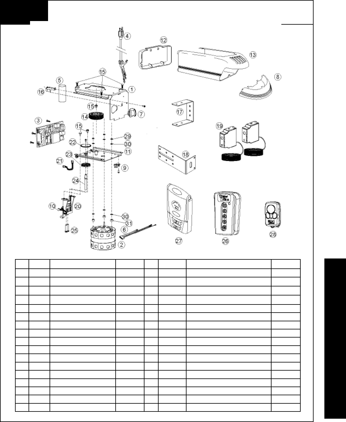
Please Do Not Return This Product To The Store. Call Us Directly! Our Trained Technicians Will Answer Your Questions and/or Ship Any Parts You May Need
You can reach us Toll Free at 1-888-827-3667 for Consumer Assistance or online at www.wayne-dalton.com
37
Parts Breakdown Opener Assembly And Accessories - All Models
#. Part # Description # Per Unit #. Part # Description # Per Unit
1. 157167 Frame 1 16. 301675 Capacitor Clamp 1
2. 325017 Motor 1/2 HP 1 17. 157166 Wired Sensor Mounting Bracket 2
3. 306131 Motor Control Board 1 18. 157165 Wired Sensor Sliding Bracket 2
4. 306364 Power Supply Cord 1 19. 318873 Infrared Safety Sensors - Pair 1
5. 260570 Capacitor 1/2 H.P. 1 20. 252092 Limit Assembly (Includes Items #10, 26 & 27) 1
6. 306486 Wiring Harness 1 21. 249321 LED Interrupter 1
7. 269028 Light Socket 1 22. 260556 Limit Driver Gear 1
8. 260552 Lens 1 23. 157039 Interrupter Disk 1
9. 252994 MOV Surge Suppressor 1 24. 260557 Shaft, Limit Driver 1
10. 252993 Limit Switch 1 25. 157055 Limit Adjuster 2
11. 325567 Sub-Frame 1 26. 306134 5 Button Wireless Keyless Entry 1
12. 325067 End Cap (Blue) 1 27. 311365 Wireless Multi Function Wall station 1
325093 End Cap (Black) 1 28. 312962 3 Button Mini Transmitter 1 or 2
13. 325066 Housing (Blue) 1 29. 157666 Hex Nut #10-32 3
325092 Housing (Black) 1 30. 157585 Lock Washer # 10 6
14. 325020 Gear Driven 1 31. 157496 Nylon Motor Spacer 3
15. 251248 Screw 1/4”-20x3/8” 7
PARTS BREAKDOWN
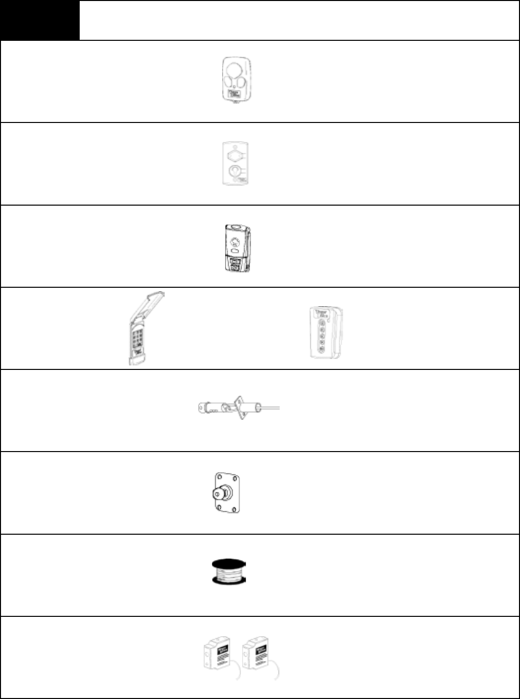
Please Do Not Return This Product To The Store. Call Us Directly! Our Trained Technicians Will Answer Your Questions and/or Ship Any Parts You May Need
You can reach us Toll Free at 1-888-827-3667 for Consumer Assistance or online at www.wayne-dalton.com
38
Three Button Mini / Visor
Transmitter
Wired Deluxe Wall Station
Controls up to 6 doors or wireless accessories.
Includes visor clip.
Wireless Multi-Function RF
Wallstation
Wireless Keyless Entry
Key Cable Outside Disconnect
Outside Key Switch
Wire Spool
Wired Infrared Safety Sensors
Allows independent door up/down control and
overhead light on/off control.
Completely wireless unit with independent door
up/down control, light on/off control, custom pet
opening, delay exit timer, and program button.
5 digit numeric keypad which allows the operation
of the garage door opener from outside by entering
a programmable personal code on a keypad. Can be
programmed to hundreds of doors.
Recommended for all vault type garages without an
access door
Used to open the door automatically from outside the
garage whenever the remote control is not available.
Shipped with 2 keys.
80ft. 22 gauge, 2 conductor polarized. UL listed
(CL-2, 75deg. C.).
Reversing sensors communicate with door opener
via direct wire connections to detect obstructions in
path of door and reacts by reversing door.
Prodrive™ Accessories
10 digit numeric keypad which allows the
operation of the garage door opener from
outside by entering a programmable
personal code on a keypad. Can be
programmed to hundreds of doors.
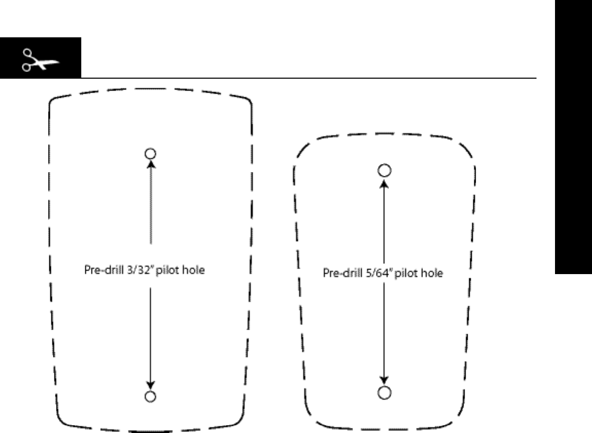
Please Do Not Return This Product To The Store. Call Us Directly! Our Trained Technicians Will Answer Your Questions and/or Ship Any Parts You May Need
You can reach us Toll Free at 1-888-827-3667 for Consumer Assistance or online at www.wayne-dalton.com
39
Cut-Out Template to Aid Installation
Multifunction
Wall Station Template
5 Button
Keyless Entry Template
DRILL TEMPLATE

Please Do Not Return This Product To The Store. Call Us Directly! Our Trained Technicians Will Answer Your Questions and/or Ship Any Parts You May Need
You can reach us Toll Free at 1-888-827-3667 for Consumer Assistance or online at www.wayne-dalton.com
40
Call Us Directly! Our Trained Technicians Will Answer
Your Questions and /or Ship Any Parts You May Need
Call Us Toll-Free:
(888) 827-3667
Thank you for your purchase
www.wayne-dalton.com
Please Do Not Return This Product To The Store

Please Do Not Return This Product To The Store. Call Us Directly! Our Trained Technicians Will Answer Your Questions and/or Ship Any Parts You May Need
You can reach us Toll Free at 1-888-827-3667 for Consumer Assistance or online at www.wayne-dalton.com
41
LIFETIME LIMITED WARRANTY
The Manufacturer warrants that the Prodrive™ Garage Door Opener’s electronic and mechanical components (excluding
motor) will be free from defects in materials and workmanship for a period of ONE YEAR (Models 3220C, 3221C, 3222C,
3320B, 3322B) and FIVE YEARS (Models 3224C, 3324B) from the date of installation, provided it is properly installed,
maintained and cared for under specified use and service.
The Motor is warranted for FIVE YEARS (Models 3220C, 3221C, 3320B) and for LIFETIME (Models 3222C, 3224C,
3322B, 3324B) against defects in materials and workmanship. Batteries are not warranted.
This Limited Warranty extends to the original homeowner, providing the Prodrive™ Garage Door Opener is installed in his/
her place of primary residence. This Limited Warranty is not transferable. The Limited Warranty applies to residential property
only.
NO EMPLOYEE, DISTRIBUTOR, OR REPRESENTATIVE IS AUTHORIZED TO CHANGE THE FOREGOING LIMITED
WARRANTY IN ANY WAY OR GRANT ANY OTHER WARRANTY ON BEHALF OF MANUFACTURER.
The Manufacturer shall not be responsible for any damage resulting to or caused by its products by reason of installation,
improper storage, unauthorized service, alteration of products, neglect or abuse, any acts of nature beyond Manufacturer’s
control (such as, but not limited to, lightning, power surges, water damage, etc.), or attempt to use the products for other
than the customary usage or for their intended purposes. The above Limited Warranty does not cover normal wear or any
damage beyond Manufacturer’s control. This Limited Warranty does not cover field
replacement labor.
THIS LIMITED WARRANTY COVERS A CONSUMER PRODUCT AS DEFINED BY THE MAGNUSON-MOSS WARRANTY ACT. NO
WARRANTIES, EXPRESSED OR IMPLIED, (INCLUDING, BUT NOT LIMITED TO, THE WARRANTY OF
MERCHANTABILITY OR FITNESS FOR A PARTICULAR PURPOSE), SHALL EXTEND BEYOND THE APPLICABLE TIME PERIOD
STATED IN BOLD FACE TYPE ABOVE.
Claims for defects in material and workmanship covered by this Limited Warranty shall be made in writing, within the
warranty period, to the dealer from whom the product was purchased. Manufacturer may either send a service
representative or have the product returned to the Manufacturer at Buyer’s expense for inspection. If judged by Manufacturer
to be defective in material or workmanship, the product will be replaced or repaired at the option of the Manufacturer, free
from all charges except authorized transportation and replacement labor. Replacement unit may be an equivalent model that
has been factory refurbished. Remainder of original Limited Warranty period will apply to repair/replacement unit.
THE REMEDIES OF BUYER SET FORTH HEREIN ARE EXCLUSIVE AND ARE IN LIEU OF ALL OTHER REMEDIES, THE LIABILITY
OF MANUFACTURER, WHETHER IN CONTACT, TORT, UNDER ANY WARRANTY OR OTHERWISE, SHALL NOT EXTEND BEYOND
ITS OBLIGATION TO REPAIR OR REPLACE, AT ITS OPTION, ANY PRODUCT OR PART FOUND BY MANUFACTURER TO BE
DEFECTIVE IN MATERIAL OR WORK SHALL NOT BE RESPONSIBLE FOR ANY DIRECT,
INDIRECT, SPECIAL OR CONSEQUENTIAL DAMAGES OF ANY NATURE.
This Limited Warranty gives you specific legal rights and you may have other rights, which may vary from state to state.
However, some states do not allow limitation on how long an implied warranty lasts or the exclusion or limitation of incidental
or consequential damages so the above limitations or exclusions may not apply to you.

FCC Regulatory Information:
This device complies with Part 15 of the FCC Rules. Operation is subject to the following two conditions: (1) this device may not cause harmful
interference, and (2) this device must accept any interference received, including interference that may cause undesired operation.
IC Regulatory Information:
This Class B digital apparatus meets all requirements of the Canadian Interference Causing Equipment Regulations. Operation is subject to the
following two conditions: (1) this device may not cause harmful interference, and (2) this device must accept any interference received, including interference that may cause undesired
operation.
NOTE: This equipment has been tested and found to comply with the limits for a Class B digital device, pursuant to Part 15 of the FCC Rules. These limits are designed to provide
reasonable protection against harmful interference in a residential installation. This equipment generates, uses, and can radiate radio frequency energy and, if not installed and used in
accordance with the instructions, may cause harmful interference to radio
communications. However, there is no guarantee that interference will not occur in a particular installation. If this equipment does cause harmful interference to radio or television
reception, which can be determined by turning the equipment off and on, the user is encouraged to try to correct the interference by one or more of the following measures: Reorient or
relocate the receiving antenna. Increase the separation between the equipment and receiver. Connect the equipment into an outlet on a circuit different from that to which the receiver is
connected. Consult the dealer or an experienced radio/TV technician for help.
WARNING: Changes or modifications to this unit not expressly approved by party responsible for compliance could void user’s authority to operate this equipment.
FCC and IC Statement
Models:
3220C, 3221C, 3222C, 3224C, 3320B, 3322B, 3324B, 3220C-Z, 3221C-Z, 3222C-Z, 3224C-Z, 3320B-Z, 3322B-Z, 3324B-Z
Covered by one or more of the following U.S. patents: D413,055; D413,579; D413,867; D421,031; D472,568; D472,910; D473,573; D473,574; D505,393; 5,929,580;
5,931,212; 6,078,249; 6,145,570; 6,161,438; 6,164,014; 6,325,134; 6,326,751; 6,326,754; 6,401,792; 6,561,255; 6,561,256; 6,568,454; 6,588,156; 6,605,910; 6,667,591;
6,739,372; 6,845,804; 6,851,465; 6,873,127; 6,880,609; 6,897,630; 6,903,650; Other U.S. and foreign patents pending.
Patent Information

INTRODUCTION
Z-Wave™ enabled prodrive™
This product is compatible with
other Z-Wave™ enabled products
Thank you for purchasing the Z-Wave™ enabled prodrive™. The Z-Wave™ enabled prodrive™
by Wayne-Dalton allows you to control your home by remote control. You can create a complete
Home Control and Access Network by combining your Z-Wave™ enabled prodrive™ with the
complete line of Wayne-Dalton’s HomeSettings products.
Endless Possibilities
HomeSettings products will allow you to easily control multiple devices in a home with the push
of a button in what is known as a “scene”. Turning on all of the lights as you come home is an
example of a scene. Dimming lights and closing your curtains to watch TV, it’s also a scene.
Install. Setup. Match. Go!
Creating a home control network is easy. Install the modules you need to control lights,
temperature, and access. Setup your scenes with a portable controller then copy them to your
prodrive garage door opener. Finish by matching a keychain remote control button to a scene.
Once you install your modules, a simple scene consisting of turning on your garage and outside
lights can be setup in less than 30 minutes.
Smart Technology
A Z-Wave™ network is a collection of modules in a mesh network. Each module acts as a
sender and a receiver using radio waves to communicate. In addition, thanks to the mesh
technology each module in the network is able to relay messages to other modules thus
increasing the reliability of the network. The more devices you add the better the network gets.
Up to 232 devices can be part of a network. All Wayne-Dalton HomeSettings products are Z-
Wave™ enabled.
Wayne-Dalton.com/access
Visit www.wayne-dalton.com/access to learn more about Wayne-Dalton’s HomeSettings line of
home control products.
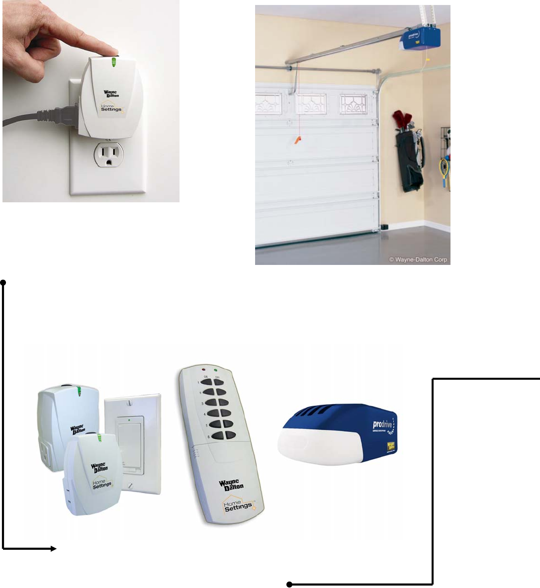
INTRODUCTION
Install your prodrive garage door opener
as outlined in the installation and owners
manual.
Setup Scenes with a portable
controller
Then.. Copy to prodrive
Install. Setup. Match. Go!
Setup
Use a portable controller to set up Scenes.
Once you create the scenes simply copy
them to the prodrive opener.
Install
Install your HomeSettings modules to
control your lights, appliances, etc. Get
ideas at www.wayne-dalton.com /access.
INTRODUCTION
Go!
Press a button on the keychain remote
control to open the door and trigger scenes.
Quick Start
Use the Quick Start guide in this
manual to learn how to create access
scenes with prodrive. The Quick
Start Guide will take you through the
Install, Setup, Match and Go! steps to
create a simple network. Once you
become familiar with the steps you
can create your own custom scenes
to match any access needs.
Match
Match a keychain remote control button to a scene
in prodrive using the Z-Wave™ interface located on
the back of the opener.
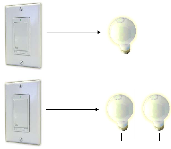
INSTALL
Install
In this example you will replace two standard 2-Way switches with two HomeSettings in-wall
dimmer switches. The HomeSettings dimmer switches are model number HA-06WD.
Follow the instructions which ship with the HA-06WD to remove the old switches and to install
the new ones.
For the example, switch one is wired to the inside garage lights. Switch two is wired to the
carriage lights outside the garage. HA-06WD in-wall dimmer switches wire exactly the same
way as a standard 2-way switch. Furthermore, once installed the HA-06WD in-wall dimmer
switches can be use manually to dim, turn off and turn on the load in the same manner as a
standard dimmer.
At this time the two in-wall light switch dimmers should be installed and working manually.
Furthermore, the prodrive opener must also be installed and working per the installation and
owners manual.
Garage
Carriage Lights
outside garage
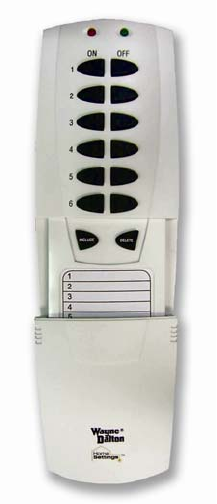
SETUP
SETUP
Once the opener and the two in-wall dimmer switches are installed it is time to set up scenes.
In order to create scenes a portable controller is needed. For this example an HA-09WD
Remote Control will be used. Other controllers such as the HA-07WD Deluxe Remote Control
or the WDHA-12R Wireless Gateway can also be used in this step.
For detailed instructions on how to use the portable remote controls please see the
documentation that ships with each controller.
To add the switches to the Network repeat the steps below for each of the two in-wall dimmer
switches.
1. Slide down the button cover on the HA-09WD Remote control to
expose the “Include” and “Delete” buttons.
2. Press and release the “include” button.
3. Press and release the dimmer’s paddle (either dim up or dim down).
4. Green LED on the Remote will light up solid momentarily indicating
success.
Create Scene 1
Once the switches are in the network you can create scenes. The scenes we
are about to create will be transferred to the prodrive opener latter on.
Prodrive can handle up to 4 scenes. Scene one is special in that it will
automatically trigger every time the door goes up and down. Furthermore, all
of the modules in scene one will automatically turn off after five minutes.
For this example we only want the inside garage lights in scene one since the
opener will turn off all modules in scene one after five minutes.
1. Press and hold simultaneously scene one “on” and “off” buttons.
2. Once the LED’s on the remote control begin to flash release the buttons.
3. Press and hold the “include” button on the remote control.
4. Press the paddle on the in-wall dimmer switch to dim up the light to full on.
5. Release the paddle on the in-wall dimmer switch.
6. Release the “include” button on the remote control.
7. The LED on the remote control will blink solid green indicating success.
Create Scene 2
Use the same process as outlined above to create scene two. Create the scene to turn on the
carriage lights only.
Create Scene 3
Use the same process as outlined above to create scene three. Add the carriage light switch in
the “off” state. In other words in step 4 above press the paddle on the in-wall dimmer switch to
turn the light off. Once you set up this scene, pressing the “on” or “off” button on scene 3 will
turn off the carriage lights.
HA-09WD
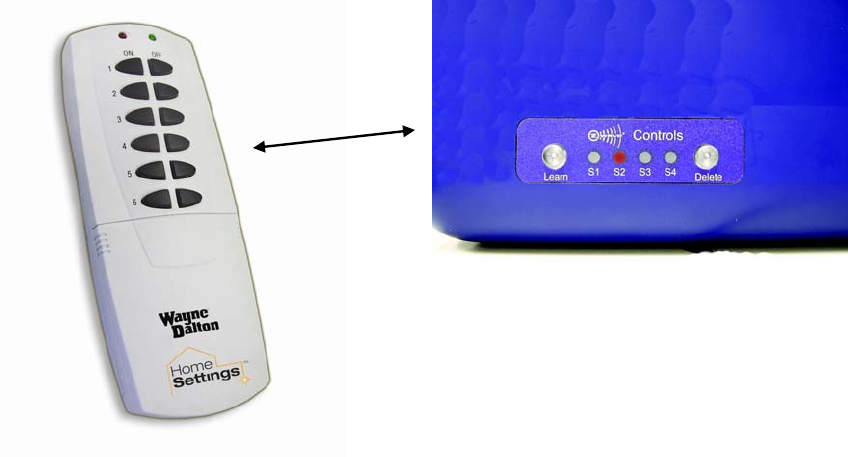
SETUP
Copy Scenes to prodrive™
Once the three scenes are created they must be copied from the HA09-WD Remote Control to
the prodrive garage door opener. To do so;
1. Press and hold the “include” button on the Remote control.
2. After five seconds the LED’s will begin flashing. Release the “include” button.
3. Press and release the scene one “on” button. The green LED will begin flashing.
4. On the prodrive, press and hold the “Learn” button located on the back of the opener.
5. Once the LED’s begin to flash release the button.
6. The copy process will take place for several seconds. Keep the HA-09WD within 3 feet
of the prodrive opener during this process.
7. The green LED on the HA-09WD remote control will flash solid green indicating success.
Z-Wave interface
(back panel on prodrive)
Kee
p
within 3 ft.
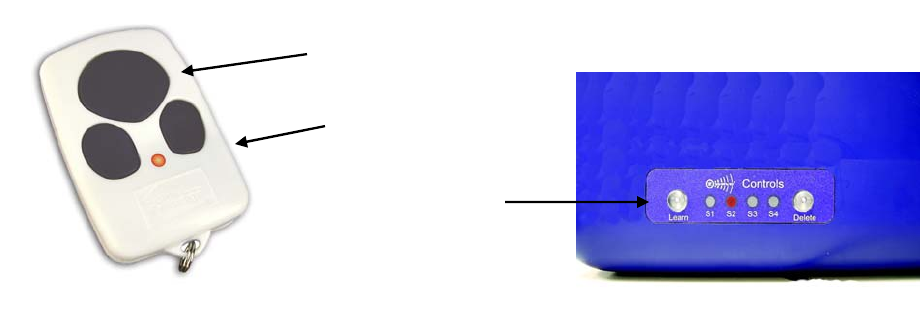
MATCH
Turn off carriage lights.
MATCH
As mentioned during the Setup process, scene one is special in that it will trigger automatically
whenever the garage door goes up and down. Therefore, there is no need to match a keychain
remote control button to scene one. All you have to do is press the keychain remote control
button already “learned” into the opener. You will see that as the door goes up or down the built
in light on prodrive will light up. Also, the garage light programmed into scene one will also light
up. Typically, the large button on the keychain remote control is used to control the garage
door. Make sure the large button on the keychain remote control activates the door.
See the prodrive installation and owners manual for instructions on how to “learn” a transmitter
button.
Matching Scene 2
For our example, we want to push a single button on the keychain remote control to open the
garage door, turn on all the lights in the garage, and also turn on the carriage lights outside.
Prodrive has the ability to trigger scene 1 and one additional scene with the same keychain
remote control button. We also want to turn off the carriage lights with another button.
To Match the large button:
1. Press and release the “Learn” button on the Z-Wave interface (back of opener). “S2”
(Scene 2) LED will light.
2. Press for one second the large button on the keychain remote control. KEEP CLEAR
OF DOOR AND OPENER AS DOOR WILL MOVE WHEN YOU PRESS THE LARGE
BUTTON.
3. Wait until the door stops motion. Once it does press the large button on the keychain
remote control. The door should move, the garage lights and the carriage lights will
light.
After five minutes the opener built-in light and the garage lights will turn off and the carriage
lights will remain on.
Control garage door, turn on garage
lights and carriage lights.
Z-Wave interface
(back panel on prodrive)
MATCH
Matching Scene 3
To complete our matching process we need to match scene 3 to one of the smaller buttons on
the keychain remote control.
To Match the smaller button:
1. Press and release the “Learn” button on the Z-Wave interface (back of opener). “S2”
(Scene 2) LED will light.
2. Press and release once again the “Learn” button on the Z-Wave interface. “S3” LED will
light.
3. Press for one second the lower right side button on the keychain remote control.
4. The “S3” LED will flash indicating successful programming.
5. Press the lower right side button on the keychain remote control. Scene 3 will trigger
turning off the carriage lights.
GO!
The prodrive opener is now setup with a basic access solution. By pressing the large button on
the keychain remote control the door will move, and the garage lights and carriage lights will
light up. After five minutes the lights in the garage automatically turn off leaving the carriage
lights on. At any time you can press the lower right hand button on the keychain remote control
to turn off the carriage lights.
With these basic building blocks you can now set up more useful access scenes. The prodrive
garage door opener can control a large number of modules with every scene. Also, the same
modules can be controlled by more than one scene.