Wayne Dalton 0001366 USB Z-WAVE ADAPTOR User Manual users manual
Wayne Dalton Corporation USB Z-WAVE ADAPTOR users manual
users manual

5015 B.U. Bowman Drive Buford, GA 30518 USA Voice: 770-831-8048 Fax: 770-831-8598
FCC Part 15.249
Transmitter Certification
Test Report
FCC ID: KJ8-0001366
FCC Rule Part: 15.249
ACS Report Number: 07-0133 - 15C
Manufacturer: Wayne-Dalton Corporation
Model: WDUSB-10
Installation Guide
This product is compatible with
other Z-Wave™ enabled products
1
Look for the symbol for basic instructions.
Quick
Sta rt
USB Z-Wave Adapter
Model WDUSB-10
Operating Instructions and Owner’s Manual
Package Contents ..................................................................................................... 1
Glossary/Basics ...................................................................................................2 - 3
Set-up .................................................................................................................4 - 6
Placement/Operation ...........................................................................................7 - 8
Advanced Features ............................................................................................9 - 13
Troubleshooting ................................................................................................14 -16
Regulatory Compliance ........................................................................................... 18
Table of Contents
Use you PC to control your Z-Wave
Home Controls System
Thank you for purchasing the WDUSB-10 Z-Wave™ USB Dongle. HomeSettings products by Wayne-Dal-
ton allow you to control your home by remote control. You can create a complete Home Control and Access
Network by combining your Z-Wave™ USB Dongle with other HomeSettings products. Indoor and outdoor
lighting, security systems, garage door openers, and thermostats are just a few of the items you can easily
control with additional HomeSettings products.
Your new Wireless Gateway is compatible with the complete range of Z-Wave™ enabled HomeSettings
products. Furthermore, other Z-Wave™ enabled modules regardless of brand will also work with your
Z-Wave™ USB Dongle. Please consult with your module supplier for more details.
Home Control Basics
HomeSettings products will allow you to easily control multiple devices in a home with the push of a button
in what is known as a “scene”. Turning on all of the lights as you come home is an example of a scene.
Dimming lights and closing your curtains to watch TV, it’s also a scene.
Visit www.wayne-dalton.com/access to get ideas on how to create scenes with your Wireless Gateway and
other Z-Wave™ enabled HomeSettings products.
PACKAGE CONTENTS
Instruction Manual WDUSB-10 USB Dongle Software CD
2
Glossary/Basics
Copy – See Replicate.
Delete – Erase a transmitter, a Z-Wave™ module or scene information from Controller. Also
known as Exclude.
Device – Any item that is connected to a module (for example, lamps).
Exclude – Remove a module, transmitter, or scene from the controller.
Include – Add a module to the controller.
Module – Any HomeSettings or Z-Wave™ product that is controlled with a HomeSettings or
Z-Wave™ remote controller. A module can be part of more than one scene.
Network – A collection of Z-Wave™ modules controlled by primary and secondary controllers
operating on the same system. A network has its own unique identification code for security.
Operator – Garage door opener or garage door operator.
Primary Controller – The first controller used to set up modules in a network.
NOTE: Only the Primary Controller can be used to include or delete modules from a network. It
is recommended that you mark the primary controller in the network for ease in modifying the
network.
Remote Control -- Garage door opener transmitter (also see Transmitter).
Replicate – Copy information from one controller to another.
Scene – A scene is a series of Z-Wave™ modules programmed to activate to a specific level (on,
off or dim) with the push of a button on a controller. The Wireless Gateway can control 3 scenes.
Secondary Controller – A controller containing a copy of the network information that is created
FROM the primary controller. Secondary controllers cannot include or delete modules to the
network.
Transmitter – Garage Door Opener transmitter.
The Z-Wave™ USB Dongle, by acting as a controller allows you to activate a multitude of Z-
Wave™ enabled modules right from your PC.
Additionally you can activate Z-Wave™ scenes directly from your PC or through a remote
connection.
GLOSSARY
USB Dongle Basics

3
Basics
The Z-Wave™ USB Dongle communicates with your -Wave™ modules using radio signals. Large
metal objects including your PC, house wiring, walls, furniture, refrigerators, microwaves and
similar items, may interfere and reduce the range of your unit. To maximize the range place the
Z-Wave™ USB Dongle in the USB stand provided and move it to an open area.
A Z-Wave™ network is a collection of Z-Wave™ modules in a mesh type of network. Each Z-
Wave™ module, regardless of manufacturer, communicates with all the other modules within its
range to route and repeat the signals from one device to the next, thus creating a highly robust
network transmission throughout the home.
A Z-Wave™ network can have only one primary controller. The primary controller establishes the
network security to ensure your network will not operate your neighbor’s network and vice-versa.
It is a good practice to label and protect your primary controller since it is the only Z-Wave™
controller that can add more modules to your network. It is easy to add secondary controllers as
your network grows.
For more tips and great ideas on how to use and expand your Z-Wave™ USB Dongle please visit
our website, www.wayne-dalton.com/access.
Wireless Gateway Basics (continued)
4
O
N
/
O
F
F
P
R
O
G
.
/
D
I
M
Green
LED on
module
Press and Release the PROGRAM
button on Module
REPLACE Use this procedure to add a Z-
Wave™ module to a Wireless Gateway scene
button.
If you have an existing Z-Wave™ network then
you must first copy the network information
from the existing primary controller to the
Wireless Gateway. First, follow the step titled
“Copy Scenes from Primary Controller to
Gateway” (page 11) to copy the existing network
information, then follow the procedure below.
Tip: Scenes can be programmed to turn all
modules on, off, dim or a combination of on ,off
and dim.
NOTE: Perform this procedure while the
Wireless Gateway is battery powered only.
Do not plug the Wireless Gateway into AC
power to program.
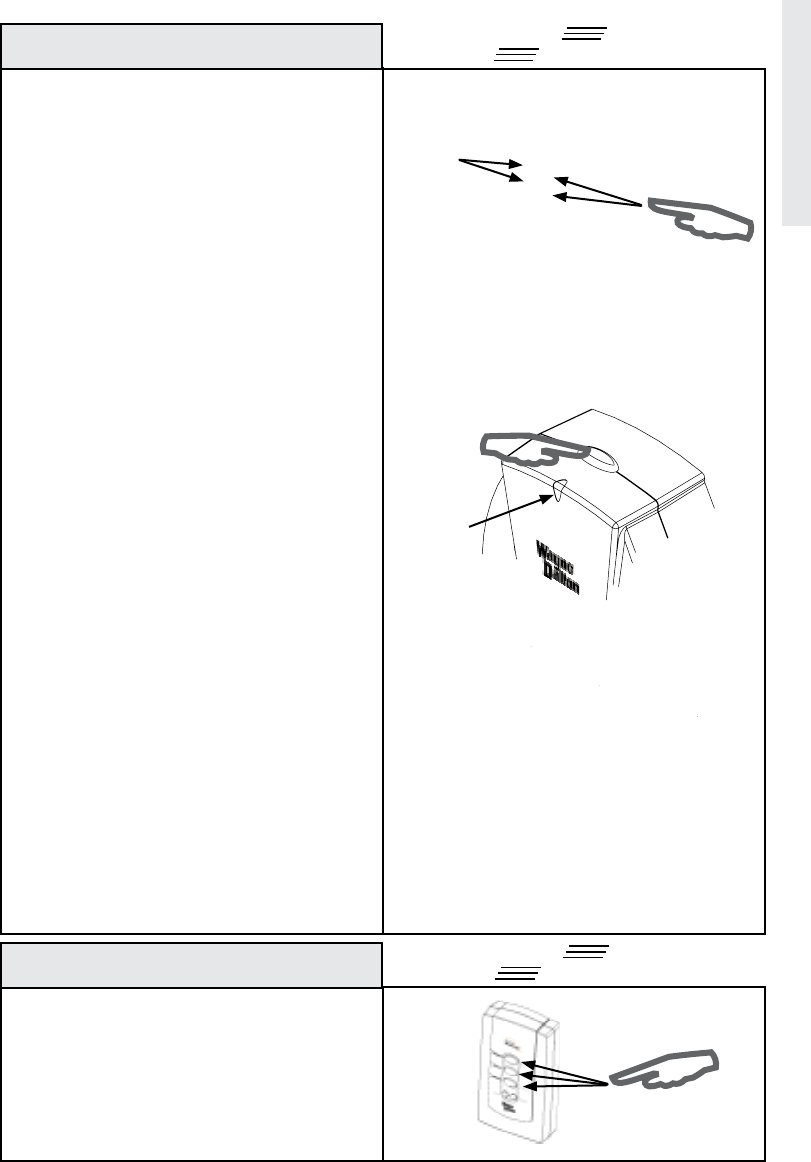
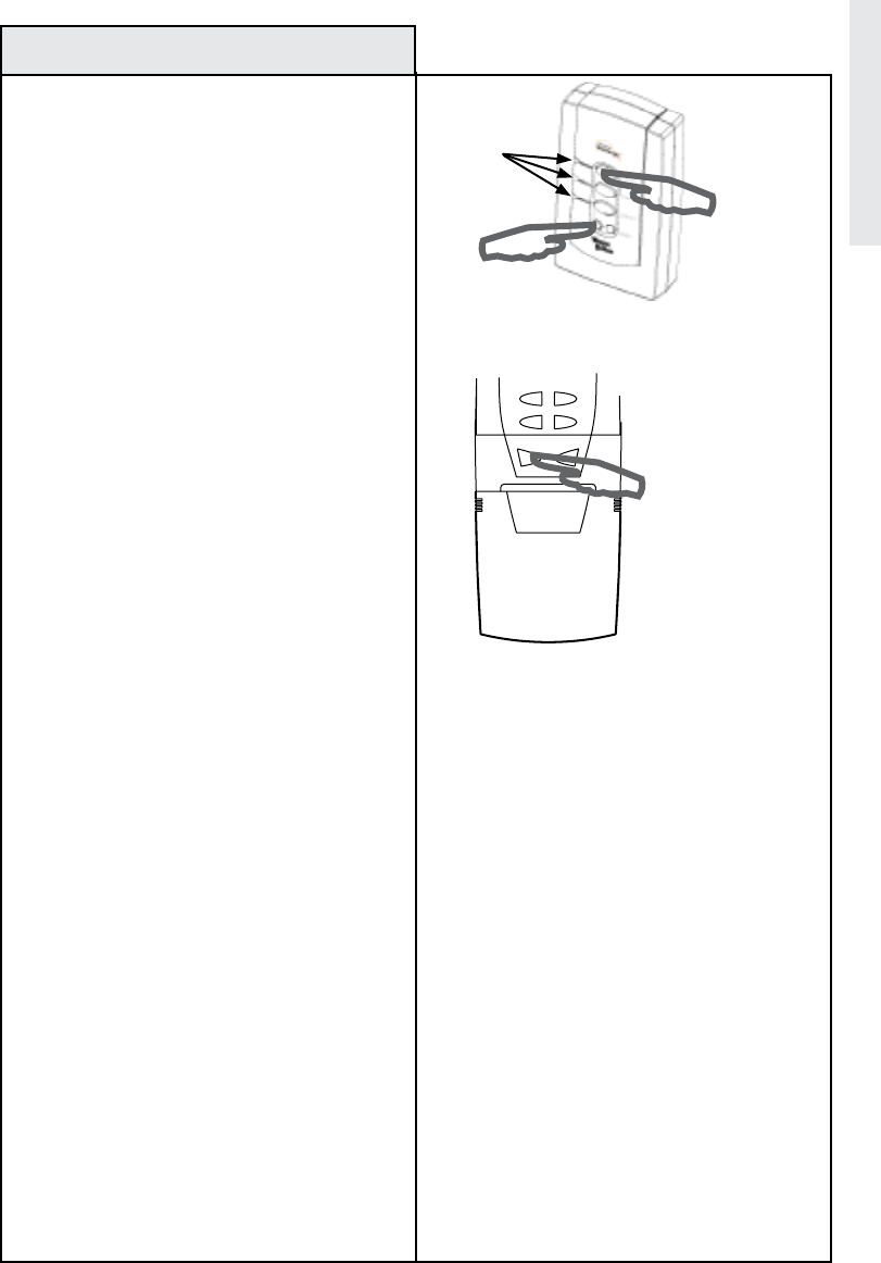
1. On the Wireless Gateway, Press and Hold the
Scene button you wish to program, (either Scene
1, 2 or 3.) The LED on the Wireless Gateway will
turn on immediately, then turn off, then turn on
again.
2. While holding the Scene button, Press and
release the OPERATE button on the Z-Wave™
module you wish to add to a scene.
The LED on the Wireless Gateway will flash three
(3) times quickly to indicate the programming
is successful. Do not release the Scene button
until you see the LED’s flash (30 second max wait.)
While holding the Scene button, Press the
OPERATE button on the Z-Wave™ module to set
the dim level or the ON/OFF state for relay type
devices.
3. Release the Scene button on the Wireless
Gateway.
Note: You may add multiple modules to each
scene button on the Wireless Gateway.
REPLACE Use the following procedure to
activate a programmed scene using the
buttons on the Wireless Gateway.
1. Momentarily Press and release the desired
Scene button (1,2 or 3) on the Wireless Gateway.
Programming a Z-Wave™ Scene
Manually Activating a Scene
Set-Up
Choose a
Scene button
Choose a
Scene button
Quick
Sta rt
Quick
Sta rt
5
Choose Button 3 on your
Car2U® transmitter
Car2U® is
a registered
trademark of
Lear Corp.
Choose a
Scene button
LED’s
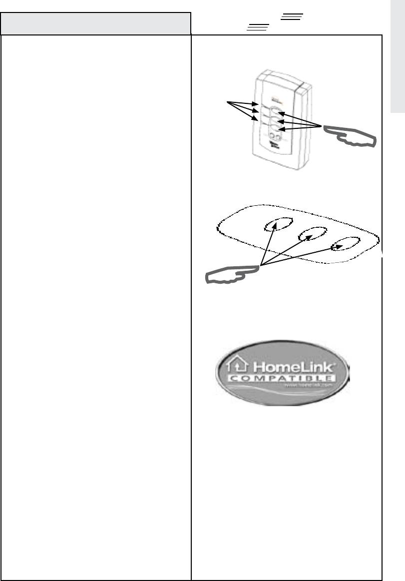
REPLACE Use the following procedure to
teach a hand held remote control transmitter
button to a scene button. This procedure
is also used to reassign a remote control
transmitter button to a different scene
button.
1. Press and Hold the scene button you wish to
program, either Scene 1, 2 or 3, until the LED
turns off, then immediately release the scene
button.
2. Press and hold the desired remote control
transmitter button.
The LED on the Wireless Gateway will flash three
(3) times quickly to indicate the programming is
successful.
3. Release the remote control transmitter button.
Note: During set-up the Wireless Gateway will
stay active for 10 seconds after programming
to allow for testing the scene. After 10 seconds
you must either plug the unit into an AC outlet or
push one of the three scene buttons to reactivate
DELETE Car2U® In-vehicle tranmsitters:
Use this procedure to teach Car2U® button
3 to a scene button. This procedure can
also be used to reassign Car2U® buttons to
a different scene button.
Note: To Program Car2U® buttons 1 or 2
to a scene button, see your vehicle owner’s
manual for instructions on programming
with rolling code receivers to change
Car2U® buttons 1 or 2.
1. Do not plug the Wireless Gateway into AC
power to program.
Press and Hold scene button you wish to
program, either Scene 1, 2 or 3, until the LED
turns off, then immediately release the scene
button.
2. Press and hold Car2U® button 3.
The LED on the Wireless Gateway will
flash three (3) times quickly to indicate the
programming is successful.
3. Release the transmitter button.
Programming to a Remote Control transmitter
Programming to In-Vehicle Mounted Remote
Control transmitters
Choose a Scene
button
LED’s
Set-Up
Remote control
Transmitter
buttons
Quick
Sta rt
Quick
Sta rt
6
The Homelink logo and trademark are
the property of Johnson Controls, Inc.
Choose a Homelink
transmitter button
Choose a
Scene button
LED’s
DELETE Homelink® in-vehicle transmitters:
Use this procedure to teach a Homelink®
button to a scene button. This procedure can
also be used to reassign a Homelink® button
to a different scene button.
1. Place the Wireless Gateway within 3 inches
of the Homelink® transceiver. The Wireless
Gateway must NOT be plugged into an AC
outlet for this operation.
2. Press and hold the desired Homelink®
button. The Homelink® LED will either flash
slowly or light on solid.
3. On the Wireless Gateway, press and hold
the Scene 1 button. The LED on the Wireless
Gateway will turn on immediately, then turn off ,
then turn on again. This is normal. Keep holding
both buttons simultaneously.
4. Keep holding both buttons until the
Homelink® transceiver LED flashes rapidly or
turns off completely. (This process may take up
to 60 seconds.)
5. Release the Wireless Gateway Scene button
and the Homelink® transceiver button.
6. On the Wireless Gateway, press and hold the
Scene button you wish to program; either Scene
1, 2 or 3 until the LED turns off, then immediately
release the Scene button.
7. Press and hold the desired programmed
Homelink® button from Step 2.
The LED on the wireless Gateway will
flash three(3) times quickly to indicate the
programming is successful.
Programming to In-Vehicle Mounted Remote
Controls (continued)
Set-Up
Quick
Sta rt
7
Choose a
Scene button
LED’s
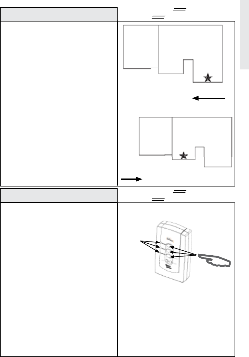
REPLACE Locate the Wireless Gateway in your
home in a convenient electrical outlet which will
give you the best performance for receiving your
in-vehicle remote control transmitter and for
transmitting the signal to other modules.
For many users the best location is in the front
corner of the home closest to their most common
approach direction which may be a dining room,
living room or bedroom. The position is indicated
in the drawings with a “Star” symbol.
Do not place the Wireless Gateway near large
metal objects such as refrigerators and freezers
or a permanently parked car that could block the
radio signal.
Note: The Wireless Gateway antenna should
be straight and positioned in the most vertical
position possible.
Use the following procedure to activate a
programmed scene.
1. Plug the Wireless Gateway into an appropriate
AC outlet.
2. Press and release the desired scene button
on the Wireless Gateway, either 1, 2 or 3.
OR
Activate Wireless Gateway scenes from your
hand held remote control transmitter or in-
vehicle mounted remote control transmitter by
pressing the transmitter button that corresponds
to the scene to which it was programmed. (See
page 5.)
Note: By default, scene 3 is pre-programmed to
ALL OFF unless Z-Wave™ modules have been
added to Scene 3, in which case only the added
modules will activate.
Tip: Scenes can be programmed to turn
all modules ON, turn all modules OFF, or a
combination of ON and OFF.
Note: A maximum of 12 remote control transmitters
can be programmed to the Wireless Gateway.
Placement of Gateway
Operation
Placement/Operation
Approach Direction
Approach Direction
Garage
Garage
House
House
Quick
Sta rt
Quick
Sta rt

8
The following examples describe how
your Wireless Gateway can be used. For
more ideas, please visit our website at
www.wayne-dalton.com/access.
1. Approaching your home in your car, you wish
to turn on the outside lights near the garage,
front door and rear door, as well as lamps in the
kitchen and family room. Wireless Gateway
Scene 1 can be programmed to turn all of these
lights ON. To operate Scene 1 from your car,
you will also need to program one button of the
remote control transmitter located in your car to
Scene 1.
2. In your car and leaving your home you wish
to turn off the outside lights near the garage,
front door and rear door, as well as interior lights.
Wireless Gateway Scene 2 can be programmed
to turn all of these modules OFF. To operate
Scene 2 from your car, you will also need to
program one button of the remote control
transmitter located in your car to Scene 2.
3. Noises outside your home awaken you during
the night. Scene 3 is programmed to turn on
only the outside lights. You can turn on Scene 3
with your Key chain Remote Control from your
bedroom to illuminate the area and scaring off
any potential intruders.
4. Lights out! You have tucked your 2 children
in bed and one has your permission to read for
15 minutes while the other has your permission
to watch TV for 15 minutes. After 15 minutes
you want to turn off their lights and TV. Scene
2 is programmed to their bedroom lights, lamps
and to a TV in the child’s room. Using your Key
chain Remote Control you can turn their lights
and TV off.
Examples require the following modules:
1 - Wireless Gateway, WDHA-12R
1 - Key chain Remote Control, 3150R (or in-
vehicle transmitter)
3 -Dimmer Switch Module HA-06WD (for each
light switch)
2 - Lamp Module, HA-03WD (for lamp in kitchen
and family room)
1 - Wireless Gateway, WDHA-12R
1 - Key chain Remote Control, 3150R (or in-
vehicle transmitter)
3 -Dimmer Switch Module HA-06WD (for each
light switch)
2 - Lamp Module, HA-03WD (for lamp in kitchen
and family room)
1 - Wireless Gateway, WDHA-12R
1 - Key chain Remote Control, 3150R
3 -Dimmer Switch Module HA-06WD (for each
light switch)
1 - Wireless Gateway, WDHA-12R
1 - Key chain Remote Control, 3150R
2 - Lamp Module, HA-03WD (for lamps in each
child’s room)
1 - Appliance Module HA-02WD (for the TV)
Examples of Scenes
Operation
9
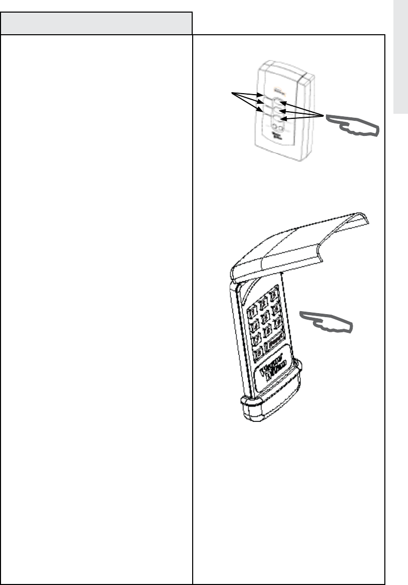
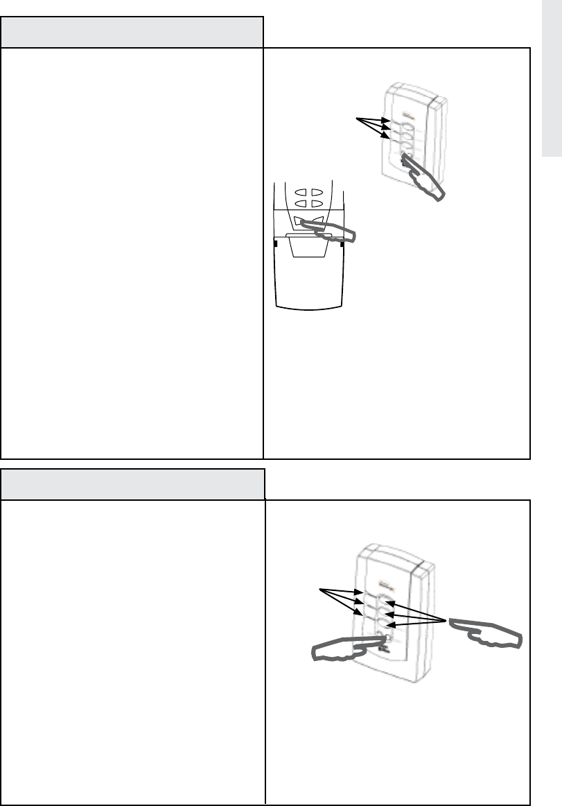
DELETE Use the following procedure to teach
a PIN keypad transmitter to a scene button.
1. On the Wireless Gateway, press and hold
the scene button you wish to program, either
scene 1, 2 or 3, until the LED turns off, then
immediately release the scene button.
2. Turn the PIN Keypad transmitter on, if
required, and type in your desired PIN Code (Be
sure you press the required number of digits for
your PIN keypad device, for example the KEP2
requires 4 digits and the Model 3966 (KEP3)
requires 5 digits.)
The LED on the Wireless Gateway will flash three
(3) times quickly to indicate the programming is
successful.
To Operate the scene from the PIN keypad
transmitter, turn the device on and type in the
PIN code for the scene you wish to activate.
Note: One PIN Keypad transmitter can operate
multiple Wireless Gateway modules.
Programming PIN Keypad Transmitters
(Keyless Entry)
Choose a
Scene button
LED’s
KEP2 PIN Code Keypad
Transmitter
Advanced Features
10
Remote Control
Transmitter
Buttons
Scene 1
Scene 2
Scene 3
Delete
LED’s Scene 1
Scene 2
Scene 3
Delete
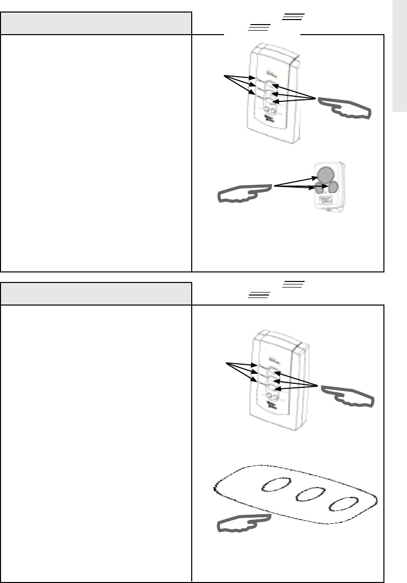
REPLACE Use this procedure to remove a
hand-held remote control transmitter or in-
vehicle mounted transmitter from a Wireless
Gateway scene button.
1. Press and release the DELETE button on the
Wireless Gateway.
All three (3) LED’s on the Wireless Gateway will
turn on.
2. Within five (5) seconds, press and release the
scene button you wish to disconnect from on the
Wireless Gateway.
The selected scene LED will stay lit for 5 seconds
and the other two will turn off.
3. Within five (5) seconds, press the in-vehicle
transmitter or hand-held remote control trans-
mitter button you wish to disconnect from the
Wireless Gateway.
The LED for the selected scene on the Wireless
Gateway will flash three (3) times quickly to
indicate a successful disconnect.
REPLACE Use the following procedure to
remove a single Z-Wave™ device from a
programmed scene. The Wireless Gateway
must not be plugged into AC outlet for this
operation.
1. Press and release the DELETE button on the
Wireless Gateway.
All three (3) LED’s on the Wireless Gateway will
turn on.
2. Within 5 seconds, press the scene button
that is associated with the device you want to
remove.
The selected scene LED will stay lit for 5 seconds
and the other two will turn off.
3. Press and release the Program button on the
Z-Wave™ device you wish to remove.
The LED on the Wireless Gateway will flash three
(3) times quickly to indicate the removal was
Remove Transmitter from Scene
Remove Z-wave™ module from a Scene
Advanced Features
O
N
/
O
F
F
P
R
O
G
.
/
D
I
M
Green LED
on module
Press and Release
Program button
on module
LED’s
Copy Scenes from Primary
Controller to Gateway
11
LED’s
REPLACE Use the following procedure to
copy scene information from a Primary
Controller. This procedure is used when you
are setting up the Wireless Gateway to an
existing Z-Wave™ network.
Note: This procedure can also be used to
make the Wireless Gateway assume the
primary controller role. Please refer to your
other controller’s instructions for information
on how to transfer Primary Controller Status
(via controller shift if supported) to a new
controller.
1. Place Wireless Gateway within 6 feet of the
primary controller.
2. Press and Hold the COPY and Scene 1 button
simultaneously for 3 seconds on the Wireless
Gateway.
After 3 seconds, the LED’s on the Wireless
Gateway will turn on. Immediately release the
COPY button. The Wireless Gateway will flash
all LED’s.
3. Within 20 seconds, start the “SEND” function
from the primary controller. Consult the
owner’s manual for your primary controller for
specific information on the “SEND” (Replicate)
command.
The LED’s on the Wireless Gateway will continue
to flash during the COPY (replication) process.
Once the LED’s turn off COPY is complete.
The Wireless Gateway is now a secondary
Controller (or primary controller if controller shift
is requested.)
Note: The process outlined above copies the
network and scene information to your Wireless
Gateway. If you are planning to create totally
new Scenes with Wireless Gateway you must
erase all copied scene information first. See
“Deleting the Contents of a Single Scene” page
12.
Advanced Features
Primary
Controller
Secondary
Controller
(Wireless
Gateway)
5
6
DELETE
INCLUDE
REPLACE Use the following procedure to
remove all Z-Wave™ modules from a single
scene on the Wireless Gateway. This will de-
lete all modules and remote control transmit-
ters from the chosen scene.
1. Simultaneously press and hold the DELETE
and the scene button you wish to reset, either
scene 1, 2 or 3 on the Wireless Gateway.
After 10 seconds the LED on the Wireless Gate-
way will flash three (3) times quickly indicating
the scene was cleared.
2. Release the buttons.
Deleting the Contents of a Single Scene
Copy Scenes from Gateway to
Secondary Controller
LED’s
REPLACE Z-Wave™ technology allows you
to create multiple duplicate controllers. The
duplicate controllers become secondary
controllers in your existing network. The
following procedure is used to send all
network and scene information to another
Controller from the Wireless Gateway. The
Wireless Gateway must be the primary
controller.
1. Place Wireless Gateway within 6 feet of the
secondary controller.
2. Place the secondary controller into “Receive
Replication” or “Copy From” mode. (See your
controller instructions for more details.)
3. Press and hold the COPY button on the
Wireless Gateway for 3 seconds . The LED’s
on the Wireless Gateway will flash rapidly
(approximately 1 flash every 1/2 second) during
the operation.
Primary
Controller
(Wireless
Gateway)
Secondary
Controller
5
6
DELETE
INCLUDE
12
Advanced Features
Choose a
Scene button
LED’s
Press and
Hold Delete
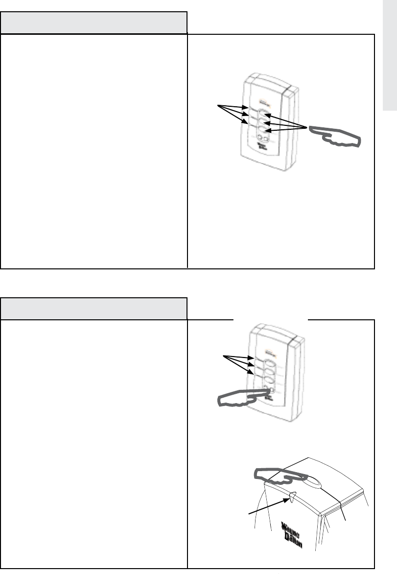
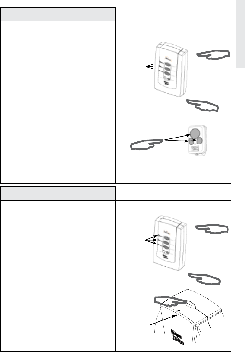
REPLACE Use the following procedure to
factory reset the Wireless Gateway. This pro-
cedure will destroy a network if the Wireless
Gateway is the primary controller.
Note: When resetting a Wireless Gateway
that is a primary controller, each module
within the network must be individually reset.
1. Simultaneously press and hold the
Scene 1, 2 and 3 buttons on the Wireless
Gateway.
After 3 seconds the LED’s on the Wireless Gate-
way will flash quickly indicating the memory was
cleared.
2. Release the buttons.
Resetting the Gateway
13
Remove a Z-Wave™ Module from the Network
LED’s
O
N
/
O
F
F
P
R
O
G
.
/
D
I
M
Green LED
on module
Press and Release
PROGRAM button on
module
REPLACE Use the following procedure to
permanently remove a single Z-Wave™
module from the Network. The Wireless
Gateway must be the primary controller for
the network.
Note: Use this feature only if you plan to per-
manently remove a module from the network.
Make sure you delete the module from all
scenes in all secondary controllers BEFORE
using this procedure.
1. Press and HOLD the DELETE button on the
Wireless Gateway until all 3 LED’s turn on then
release.
2. Press and Release the PROGRAM button on
the device you wish to remove. The LED’s on
the Wireless Gateway and Z-Wave™ module
will flash to indicate a successful operation.
Advanced Features
Press all
Scene buttons
LED’s

14
Troubleshooting
Problem:
Wireless Gateway LED’s remain lit for a long
period of time when deleting or programming.
Problem:
Modules can not be removed from the Wireless
Gateway.
Problem:
• How do I determine if my Wireless Gateway is
a primary or secondary controller?
Problem:
•When activating a Scene, the modules do not
turn on quickly and/or behave erratically.
Solution:
Momentarily plug the Wireless Gateway into an
electrical outlet to reset the device to normal
operating mode.
Solution:
The Wireless Gateway is a secondary controller
in the network, only Primary controllers can be
used to add or delete modules to a network.
Solution:
Press and hold the DELETE button for 3
seconds, if all 3 LED’s turn on the Gateway is
a primary controller, if the LED’s do not turn
on, the Gateway is a secondary controller. Do
not manually operate any Z-Wave™ modules
during this test.
Solution A:
This is a common when there is a burned out
bulb in one or more nodes. Replace the bulb.
Solution B:
If the primary controller was reset and all of
the modules and secondary controllers in the
network were not reset at the same time, then
the newly created network could exhibit this
behavior. The solution is to reset the primary
controller, all secondary controllers and all
modules in the network and then set up a new
network.
REPLACE
Troubleshooting

15
Troubleshooting
Troubleshooting
REPLACE
Problem:
• No Scenes activate when I use a Wireless Key
Chain transmitter to activate scenes, however
pressing scene buttons on the Wireless Gateway
work fine.
Problem:
• The Wireless Gateway will not program to a
Z-Wave™ enabled module.
Solution:
The Wireless Gateway must be plugged into
an AC outlet for power. Battery power is
for programming purposes only and has an
automatic time out feature.
Solution A:
The Wireless Gateway must be within 6 feet of
any Z-Wave™ module during programming.
Solution B:
Be certain you are following the correct
programming approach. Programming
Z-Wave™ modules requires that you Press and
Hold the scene button you wish to program on
the Wireless Gateway until the LED turns on,
off and then on again, then Press and Release
the Z-Wave™ module program button on the
module you want to associate with a scene.
Followed by releasing the Wireless Gateway
scene button.
Transmitters (such as Car2U, KEP2, 3966 (KEP3)
and 3150L)) require that you Press and Hold the
Scene button on the Wireless Gateway module
until the LED turns on, then off, then release the
Scene button, followed by a Press and Release
of the transmitter button you wish to program.
Solution C:
If your module is part of an existing network
you must first copy the scene information from
your primary controller to the Wireless Gateway.
See “Copy Scenes from Primary Controller to
Gateway”, page 11.
Solution D:
If your module previously belonged to another
network or you are replacing a lost or broken
primary controller then you must first delete the
module from the old network prior to adding it
to the new primary controller. See “Remove a
Z-Wave™ Module From the Network”, page 13.

Troubleshooting
REPLACE
Problem:
• A previously programmed remote control
transmitter no longer works.
Problem:
• I activated a scene but wish to abort the
execution of that scene before it is complete.
Problem:
• The range of the remote control transmitter I
use to activate the Wireless Gateway is reduced.
Problem:
• Modules take a long time to respond to a
command
Problem:
• The Wireless Gateway works fine when
plugged into an AC outlet but when used in hand
held mode nothing works.
OR
• The Wireless Gateway behaves erratically
and/or appears to lock up when creating scenes
or removing modules from scenes or from the
network.
Solution:
The Wireless Gateway holds a maximum of 12
remote control transmitters, after which the last
one is replaced.
Solution:
Using a remote control transmitter such as the
Car2U®, Homelink®, 3150R, KEP2, or 3966
(KEP3), by pressing any previously programmed
scene other than the one you just activated, you
will abort the current scene.
Solution A:
Your remote control transmitter may need fresh
batteries, replace if necessary.
Solution B:
Check to be sure the Wireless Gateway antenna
is in the most vertical position.
Solution C:
Check the area around the Wireless Gateway
for any large metal objects which could be
interfering with the antenna reception.
Solution:
Check that all Z-wave™ modules are on
and working, the Wireless Gateway may be
searching for a module that may have been
disconnected, moved, or has failed. Check for
burned out light bulbs in lamps controlled by
Z-wave™ modules and replace if necessary.
Solution:
Wireless Gateway battery needs to be replaced.
Open unit with a small philips head screwdriver
and replace the 9V battery, then reassemble the
Wireless Gateway. WARNING: DO NOT PLUG
THE WIRELESS GATEWAY INTO AC POWER
WHEN THE COVER IS REMOVED.
Troubleshooting
16
This page intentionally left blank.
17

FCC and IC Statement
FCC Regulatory Information:
NOTE: This equipment has been tested and found to comply with the limits for a Class B digital device, pursuant to Part 15
of the FCC Rules. These limits are designed to provide reasonable protection against harmful interference in a residential
installation. This equipment generates, uses, and can radiate radio frequency energy and, if not installed and used in
accordance with the instruction, may cause harmful interference to radio communications. However, there is no guarantee
that interference will not occur in a particular installation. If this equipment does cause harmful interference to radio or
television reception, which can be determined by turning the equipment off and on, the user is encouraged to try and correct
the interference by one or more of the following measures:
a) reorient or relocate the receiving antenna,
b) increase the separation between the equipment and receiver,
c) connect the equipment into an outlet on a circuit different from that to which the receiver is connected.
Consult the dealer or an experienced radio/TV technician for help.
IC Regulatory Information:
This Class B digital apparatus meets all requirements of the Canadian Interference Causing Equipment Regulations. Operation
is subject to the following two conditions: (1) this device may not cause harmful interference, and (2) this device must accept
any interference received, including interference that may cause undesired operation of the device.
Cet appareillage numérique de la classe B répond a toutes les exigences de l’interférence canadienne causant des règlements
d’équipement. L’opération est sujette aux deux conditions suivantes: (1) ce dispositif peut ne pas causer l’interférence nocive,
et (2) ce dispositif doit accepter n’importe quelle interférence reçue, y compris l’interférence qui peut causer l’opération peu
désirée.
WARNING: Changes or modications to this receiver not expressly approved by Wayne-Dalton Corp. could void the user’s
authority to operate this equipment.
You can reach us for Consumer Assistance at homesettings@wayne-dalton.com
or online at www.wayne-dalton.com/access
© Copyright 2007 Wayne-Dalton Corp. Part No. 0001676 rev 2 New 04/26/07
Z-Wave™ is a trademark of Zensys Corp.
18
Compliance