Wayne Dalton 0002119 Remote Control Light User Manual 339 xxx New 9 22 08 indd
Wayne Dalton Corporation Remote Control Light 339 xxx New 9 22 08 indd
User Manual
Tools Needed:
Step Ladder
Phillips Screw Driver
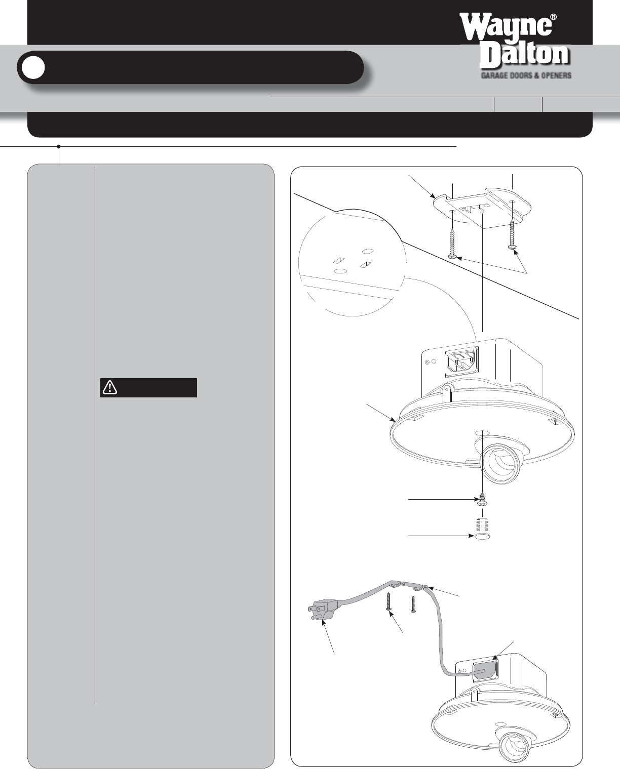
Select a grounding type receptacle on either
the ceiling or wall. If one is not available, have
one installed by a qualified electrician.
IMPORTANT! DOOR MUST CLEAR LIGHT
FIXTURE WHEN THE DOOR IS IN THE OPEN
POSITION.
Identify a mounting location for the light fixture
that’s in close proximity to the receptacle, and
within reaching distance of the power cord.
Fasten the mounting bracket to a stud, in the
desired location using (2) #10 x 1-1/2” deep
thread screws. Align the two metal tabs on the
mounting bracket. Hold the light fixture flush
against the mounting bracket using (1) #8 x
0.375” screw as shown. Place the hole plug
into the screw hole in the light fixture.
NOTE: For temperature protection, the hole
plug must be in place prior to using the light
fixture.
TO AVOID ELECTRICAL SHOCK/FIRE,
DO NOT CHANGE THE POWER CORD
PLUG IN ANY WAY.
IMPORTANT! THE POWER CORD HAS A
GROUNDING TYPE PLUG WITH A THIRD
(GROUNDIING) PIN. THIS PLUG WILL ONLY FIT
INTO A GROUNDING TYPE OUTLET. IF THE
PLUG DOES NOT FIT INTO YOUR OUTLET,
CONTACT A QUALIFIED ELECTRICIAN TO
INSTALL THE PROPER GROUNDING TYPE
OUTLET. DO NOT ALTER THE PLUG IN ANY
WAY.
Plug the female end of the power cord into the
inlet connect of the light fixture. Now, plug the
other end of the power cord into the nearest
grounding type receptacle. As soon as power is
applied to the light fixture it should blink one
time. Use cable clips and #6 x 7/8” wood
screws to secure the power cord.
Z-WAVE LIGHT KIT INSTALLATION
FOR TORSION I-DRIVE
Installation Instructions P.O. Box 67 Mt. Hope, OH 44660
GARAGE DOORS & OPENERS
© 2008 Wayne-Dalton Corp. Part No. 33xxxx New 9/22/2008
www.wayne-dalton.com
This insert is to be used in conjunction with the main installaton instructions and owner’s manual.
This insert is for Z-Wave I-Drive TorqueMaster® Pro Operator Only!
WARNING
Mounting Bracket
(P/N 293294)
#8 x 0.375”
Phillips Pan Head
Screw
Hole Plug-Snap In
(P/N 311122-6)
(ITW Fastex 354-310102-00-2099)
(2) #10 x 1-1/2” Deep Thread
Screws (P/N 279995)
Light Fixture
Wire Clips
#6 x 7/8” Wood
Screws
Plug into nearest outlet
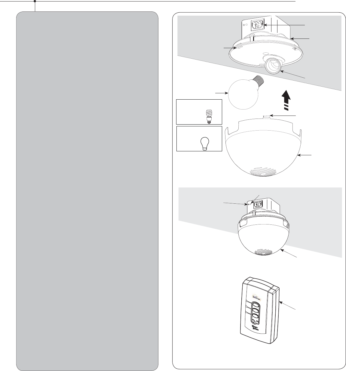
Screw a 15W Type-A bulb or 19W Compact
Fluorescent (maximum) light bulb into light
socket and snap diffuser into light fixture.
NOTE: When assembling diffuser, make sure
all three snap tabs are aligned and fully
snapped into the three mating slots of the
light fixture.
Turn receptacle power back on at fuse/breaker
box. The light should blink one time when the
power is turned back on.
IMPORTANT: FOR REPLACEMENT BULBS USE
ONLY 19W MAX COMPACT FLUORESCENT
BULBS OR USE ONLY 15W MAX TYPE-A
BULBS FOR THE LIGHT.
Top portion of Light
Fixture
Inlet Connector
Pg 1
Programming the Z-Wave Light Kit to the i-Drive TorqueMaster
Pro.
If your Z-Wave Light Kit is included with the opener, it should
already be programmed to the opener. Otherwise, follow the
instructions below.
IMPORTANT: ERASE ANY EXISTING PROGRAMMING ON
Z-WAVE LIGHT KIT
1. Press and hold the DELETE button on the unplugged
Wireless Gateway until the 3 LEDs turn on, then let go of the
button.
2. Press the red button on the Z-Wave Light Kit and
observe the LEDs on the Wireless Gateway flash. All network
programming, if any, has now been deleted from the Z-Wave
Light Kit. Press the red button again to turn off the light. If the
button is held in, the Z-Wave Light Kit may flash its light on
and off repeatedly. This is okay.
PROGRAM Z-WAVE LIGHT KIT TO PRIMARY CONTROLLER
1. Insure the Z-Wave Light Kit light is off.
2. Press the Scene 1 button on the Wireless Gateway and
observe that the LED lights up. Continue holding the button
down until the LED turns off and the turns back on again.
3. While the Scene 1 button is still being pressed, press
the red button on the Z-Wave Light Kit, while observing the
LED for Scene 1. If the LED flashes, the Z-Wave Light Kit has
been successfully programmed to Scene 1 of the Wireless
Gateway.
4. Release the button on the Wireless Gateway.
5. Note: If the programming was unsuccessful, try moving
the Wireless Gateway closer to the Z-Wave Light Kit or change
orientation.
COPY PRIMARY CONTROLLER PROGRAM TO THE Z-WAVE
OPERATOR
1. Press and hold the Learn button on the I-Drive
TorqueMaster® Pro until all 4 LEDs are blinking. Release the
button.
2. With the Wireless Gateway in close proximity to the
I-Drive TorqueMaster® Pro, press and hold the copy button on
the Wireless Gateway until all 3 LEDs are flashing.
3. Observe the 4 LEDs on the I-Drive TorqueMaster® Pro. If
programming is successful, the LEDs will begin blinking at a
different rate, and then turn off. If not, then you may have to
move the Wireless Gateway closer or change the orientation.
4. The Z-Wave Light Kit will now come on when the
operator is engaged. The light will automatically shut off after
approximately 5 minutes. Additionally, by default, Scene 3 will
turn off Scene 1. Therefore, the light can be turned off by
pressing Scene 3 on the Wireless Gateway.
Programming the Z-Wave Light Kit
Scene 1
Scene 2
Scene 3
Delete
Copy
Program Button
Light Button
LED
Light Fixture
Diffuser
Light Bulb
(Not Included)
Power Socket
Snap Tabs
(3) Mating Slots
Light Socket
Caution! Risk of Fire
Use Only 15W Max.
TYPE- A
Caution! Risk of Fire
Use Only 19W Max.
COMPACT
FLUORESCENT
Pg 2
Wireless Gateway
FCC and IC Statement
FCC Regulatory Information:
This device complies with Part 15 of the FCC Rules. Operation is subject to the following two conditions: (1) this device may not cause
harmful interference, and (2) this device must accept any interference received, including interference that may cause undesired
operation.
IC Regulatory Information:
Operation is subject to the following two conditions: (1) this device may not cause interference, and (2) this device must accept any
interference, including interference that may cause undesired operation of the device.
NOTE: This equipment has been tested and found to comply with limits for a Class B digital device, pursuant to Part 15 of FCC Rules.
These limits are designed to provide reasonable protection against harmful interference in a residential installation. This equipment
generates, uses and can radiate radio frequency energy and, if not installed and used in accordance with these instructions, may cause
harmful interference to radio communication; however, there is no guarantee that interference will not occur in a particular installation. If
this equipment does cause harmful interference to radio or television reception, which can be determined by turning equipment off and
on, user is encouraged to try to correct interference by one or more of the following measures: Reorient or relocate receiving antenna.
Increase separation between equipment and receiver. Connect equipment into an outlet on a circuit different from that which receiver is
connected. Consult your dealer or/and experienced radio/television technician for help.
WARNING: Changes or modifications to this unit not expressly approved by party responsible for compliance could void user’s authority
to operate this equipment.
Patent Information
Models:
3790/3790-Z
Made under the following US patents and methods D413,579; D466,141; D472,568; D472,910; D473,573; D473,574;
D474,215; D505,393; D517,580; CA 2,348,784; 5,929,580; 6,078,249; 6,145,570; 6,164,014; 6,253,824; 6,263,947;
6,325,134; 6,326,751; 6,326,754; 6,401,792; 6,561,255; 6,561,256; 6,568,454; 6,588,156; 6,605,910; 6,667,591; 6,739,372;
6,845,804; 6,851,465; 6,873,127; 6,880,609; 6,903,650; 7,053,571; 7,061,197; 7,075,256; 7,109,677; 7,123,128; 7,143,804;
7,173,389; 7,173,514; 7,173,516; 7,183,732; 7,190,266; 7,193,502; 7,207,142; 7,211,975; 7,246,647; 7,280,031; 7,327,107;
7,327,108; 7,327,249; 7,358,480; 7,367,160; 7,375,484; 7,375,612; 7,376,401;7,397,342. Other US and Foreign Patents
pending.