Wayne Dalton 0003177 ROOM KEY CONTROLLER User Manual XX XXXX Exhibit Cover
Wayne Dalton Corporation ROOM KEY CONTROLLER XX XXXX Exhibit Cover
Manual

5015 B.U. Bowman Drive Buford, GA 30518 USA Voice: 770-831-8048 Fax: 770-831-8598
Certification Exhibit
FCC ID: KJ8-0003177
IC: 3540A-0003177
FCC Rule Part: 15.249
IC Radio Standards Specification: RSS-210
ACS Report Number: 09-0189-15C
Manufacturer: Wayne-Dalton Corporation
Model: WDHKC-50
Manual

1
Room Key Controller
Model: WDHKC-50
Description
The Room Key Controller is a battery operated Generic Z-Wave controller capable of
triggering one Z-wave scene with up to 230 devices. When a generic room key card is
inserted in the card slot, the Z-Wave scene triggers. The controller then goes to sleep to
save batteries. When the room key card is removed all devices included into the scene
will trigger to the “off” state. Thermostats trigger to the “normal” mode when the card is
inserted, and to the “energy save” mode when the card is removed. Heat and cool are
selected automatically by a threshold. Out of the factory, the thermostat threshold is set
to 72deg. F. If the ambient room temperature is cooler than the threshold, the thermostat
will switch to a heating mode. If the temperature is warmer than the threshold the
thermostat will switch to a cooling mode.
The Room Key Controller will send commands to devices supporting the basic command
set. Light fixtures, thermostats, window coverings, etc. can be set to a particular level as
long as they support the Z-Wave standard basic command set.
Package Contents
• Room Key Controller.
• Wall Bracket.
• Instruction Manual.
• Battery (123A).
• Faceplate screws (2).
• Wall Bracket screws (2).
Special Operation Modes
Thermostat Set Points
The Controller supports custom temperature settings for thermostats. There are four
supported modes listed below;
Energy save cool
Energy save heat
Cool
Heat

2
To set the custom temperatures, simply power up the thermostat to be added to the
network and set the modes at the desired temperatures. This must be done before adding
the thermostat to the Room Key Controller. The Room Key Controller will grab the
temperature set points from the thermostat when it is added to the network. Multiple
thermostats are supported but only the temperatures from the first thermostat will be
recorded. The Room Key Controller will always set all thermostats in the room to the
same temperature.
This mode of operation is particularly useful when hotel guests manually change the
thermostat temperature. Once the card is inserted or removed, all thresholds will go back
to the originally programmed setting.
Custom Set Points Re-Programming
To set new custom set points for the Room Key Controller follow the following
procedure:
1. Power down all thermostats in the room.
2. Insert the key card in the slot. Wait 15 seconds.
3. Remove key card from the slot. Wait 15 seconds.
4. Power up all thermostats in the room and set all of the thresholds manually in the
thermostats.
5. Insert the key card in the slot. –Room Key Controller will grab the new thresholds
and program them into non volatile memory.
Stand Alone \ Indicator Mode
The Room Key Controller can be configured to act in Stand Alone mode (factory default)
where all control functions for the room are controlled by the Room Key Controller or in
Indicator mode where the Controller switches from Room Controller to Key
insertion\removal sensor. In this mode, the Room Key Controller sends key status
information to another controller such as Hotel Manager AG. When the Room Key
Controller is reset, it will automatically go to Stand Alone mode. Indicator mode can be
set via the parameter command which is only accessible with a compatible Controller.
PARAMETER #
PARAMETER
NAME DEFAULT
DESCRIPTION
VALID
VALUES
1 Stand Alone 1 Sets Stand Alone mode (1)
or Indicator mode (0)
0-1
3
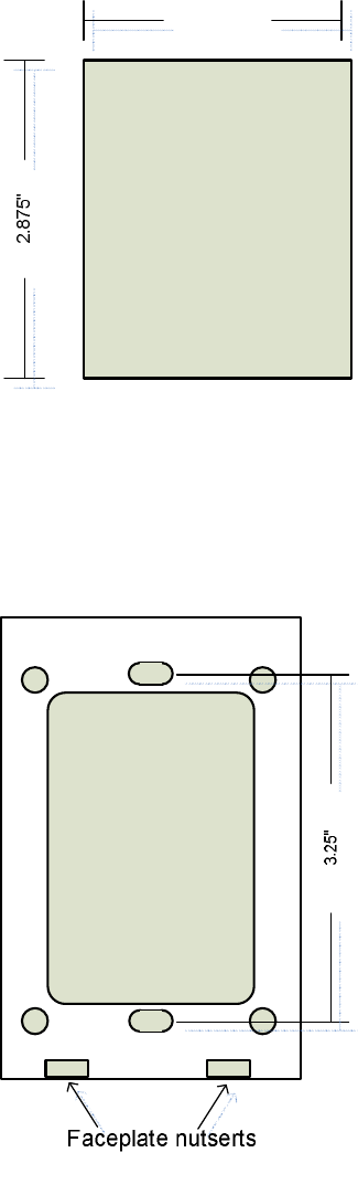
Installation
1. Cut a hole in the wall at the desired mounting location with the measurements
listed in figure 1
FIGURE 1
2. Use appropriate hardware to mount wall bracket aligned with the hole in the wall.
Make sure the smooth side of the wall bracket is facing the wall and the rib side is
facing out. Also make sure to orient the wall bracket with the faceplate nutserts
facing down. See Figure 2.
FIGURE 2
4
Z-Wave Setup
NOTE: The Room Key Controller supports the following Z-Wave functions.
• Add Z-Wave Node to Scene with Level and promote to primary (when
adding controllers).
• Remove Node from Scene and Network.
• Factory Reset.
• Join existing network with scenes.
• Inclusion Controller.
NOTE: Features not supported by Room Key Controller.
• Replicate Network out.
• Scene Command Class.
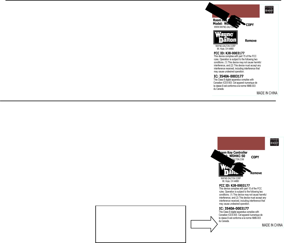
Add Z-Wave Node to Network and Scene
1. Press “COPY” button. LED will flash. Release.
2. Press the operate button on the Z-Wave node you want to add
to the network. At this time you may also set the level
(dimmers).
3. Release the operate button on the Z-Wave node.
4. LED will turn off indicating success.
NOTE: If a controller is added to the network it will be promoted
to primary.
Join Existing Network with Scenes.
1. Place the sending (primary) remote into replication send with
scenes.
2. Simultaneously, insert Room Key into Room Key Controller
slot and press and hold the “REMOVE” button. LED will
begin to flash.
3. Keep holding until LED lights solid for one second.
4. LED will continue blinking during replication.
5. Replication is complete when LED turns off.
NOTE: All nodes in scene 1 of sending remote will be copied into the
Room Key Controller.
ROOM KEY
5
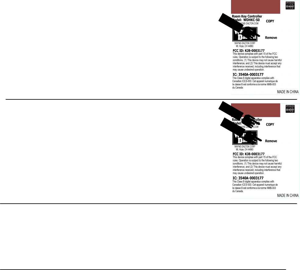
Remove Node from Network and Scene
1. Press the “REMOVE” button. LED will flash. Release.
2. Press the operate button on the Z-Wave node you want to delete
from the network. Release.
3. LED will turn off indicating success.
Factory Reset
1. Press and hold the “COPY” and “RESET” buttons.
2. Hold the buttons until the LED Turns on (about 5 seconds).
3. Release buttons.
4. The LED will flash 10 indicating success.
NOTE: This is a destructive function. All Z-Wave nodes in the
network will have to be reset if this function is used.
Faceplate Installation
1. Place the Room Key Controller into the Wall Bracket. The Faceplate has two
dimples on top which match with two top dimples on the Wall Bracket.
2. Use the two screws provided to secure the Faceplate to the Wall Bracket.
NOTE: The screws fit from the bottom of the Faceplate into the nutserts in the Wall
Bracket.
Regulatory Information
US and Foreign patents pending.
Z-Wave® is a registered trademark of Zen-sys Corporation.
Wayne-Dalton® is a registered trademark of Wayne-Dalton Corporation.
FCC Regulatory Information
NOTE: This equipment has been tested and found to comply with the limits for a Class B digital device,
pursuant to Part 15 of the FCC Rules. These limits are designed to provide reasonable protection against
harmful interference in a residential installation. This equipment generates, uses, and can radiate radio
frequency energy and, if not installed and used in accordance with the instruction, may cause harmful
interference to radio communications. However, there is no guarantee that interference will not occur in a
particular installation. If this equipment does cause harmful interference to radio or television reception,
6
which can be determined by turning the equipment off and on, the user in encouraged to try and correct the
interference by one or more of the following measures:
a) reorient or relocate the receiving antenna,
b) increase the separation between the equipment and receiver,
c) connect the equipment into an outlet on a circuit different from that to which the receiver is
connected.
Consult the dealer or an experienced radio/TV technician for help.
IC Regulatory Information
This class B digital apparatus meets all requirements of the Canadian Interference Causing
Equipment Regulations. Operation is subject to the following two conditions: (1) this device may
not cause harmful interference, and (2) this device must accept any interference received,
including interference that may cause undesired operation of the device.
Cet appareillage numérique de la classe B répond a toutes les exigences de l’interférence
canadienne causant des règlements d’équipement. L’opération est sujette aux deux conditions
suivantes : (1) ce dispositif peut ne pas causer l’interférence nocive, et (2) ce dispositif doit
accepter n’importe quelle interférence reçue , y compris l’interférence qui peut causer l’opération
peu désirée.
WARNING : Changes or modifications to this receiver not expressly approved by Wayne-Dalton
Corp. could void the user’s authority to operate this equipment
© Copyright 2009 Wayne-Dalton Corp. Part No.0003229 Rev. C New 7/8/2009
For Assistance, you may reach us online at www.wayne-dalton.com/access