Wayne Fueling Systems WAYNETRAC User Manual
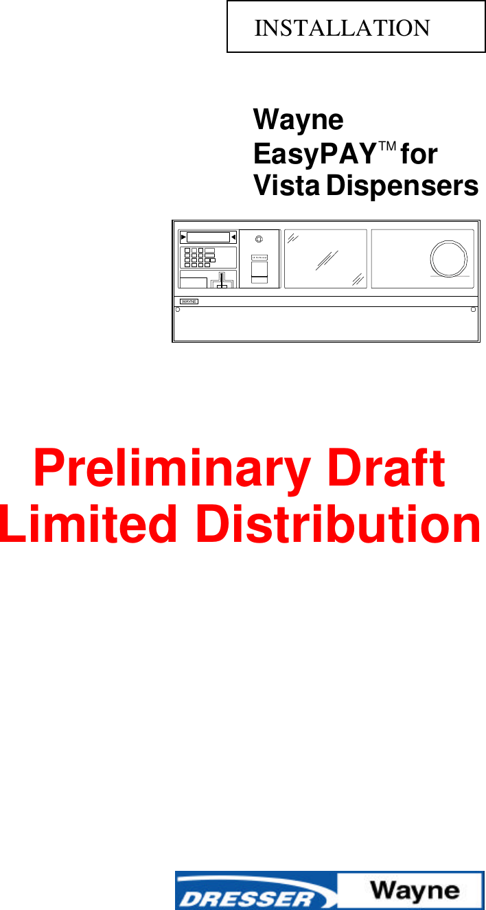
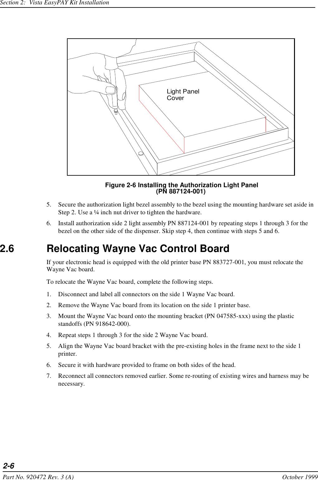
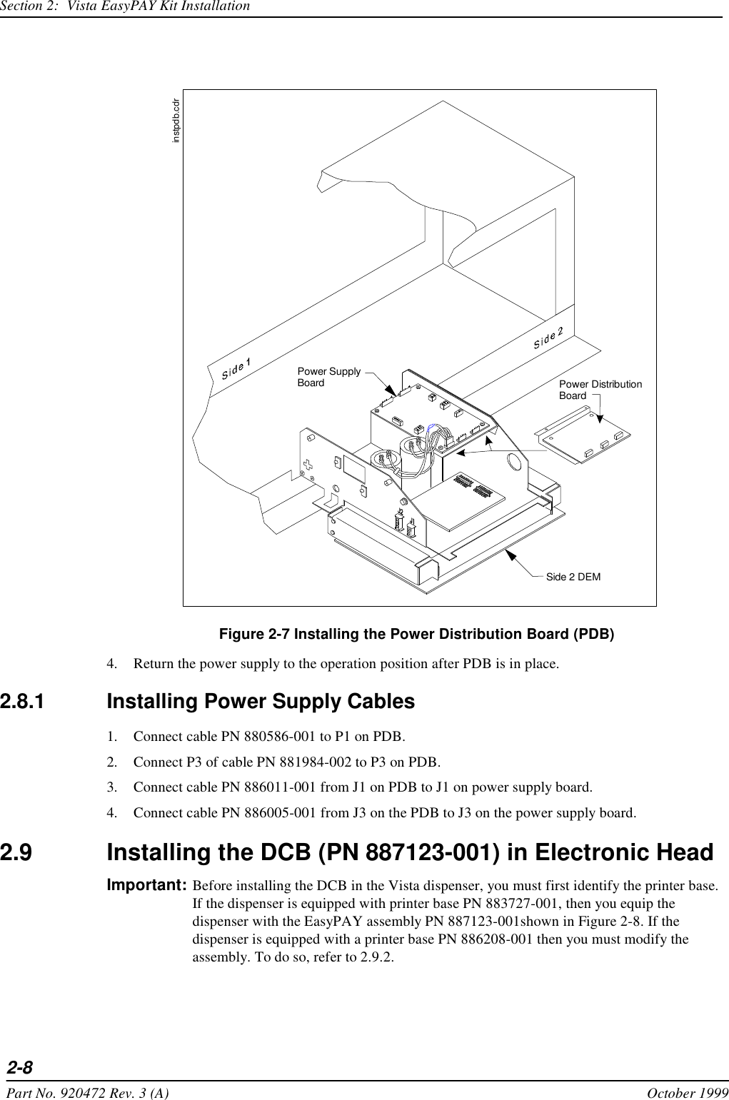
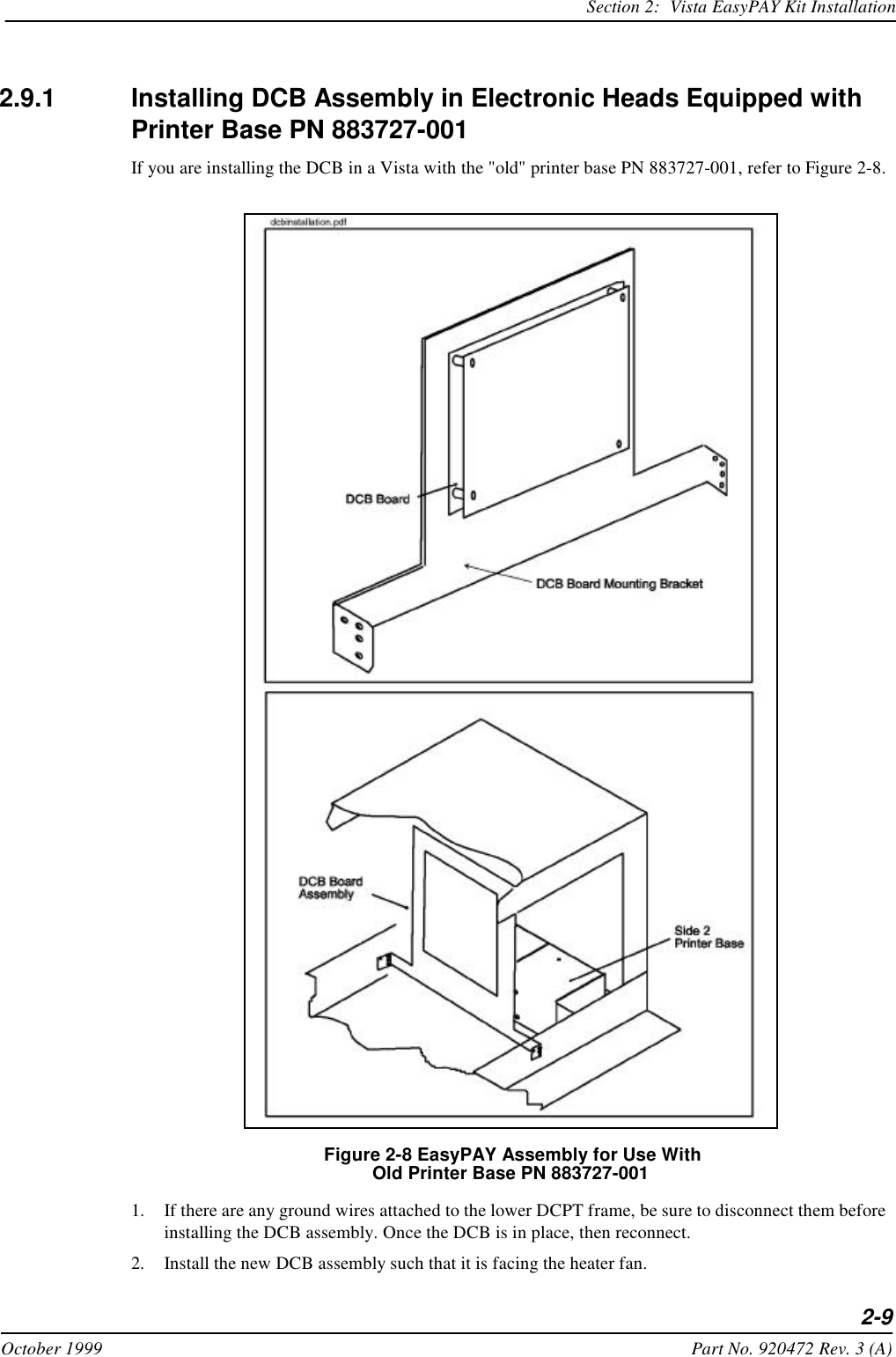
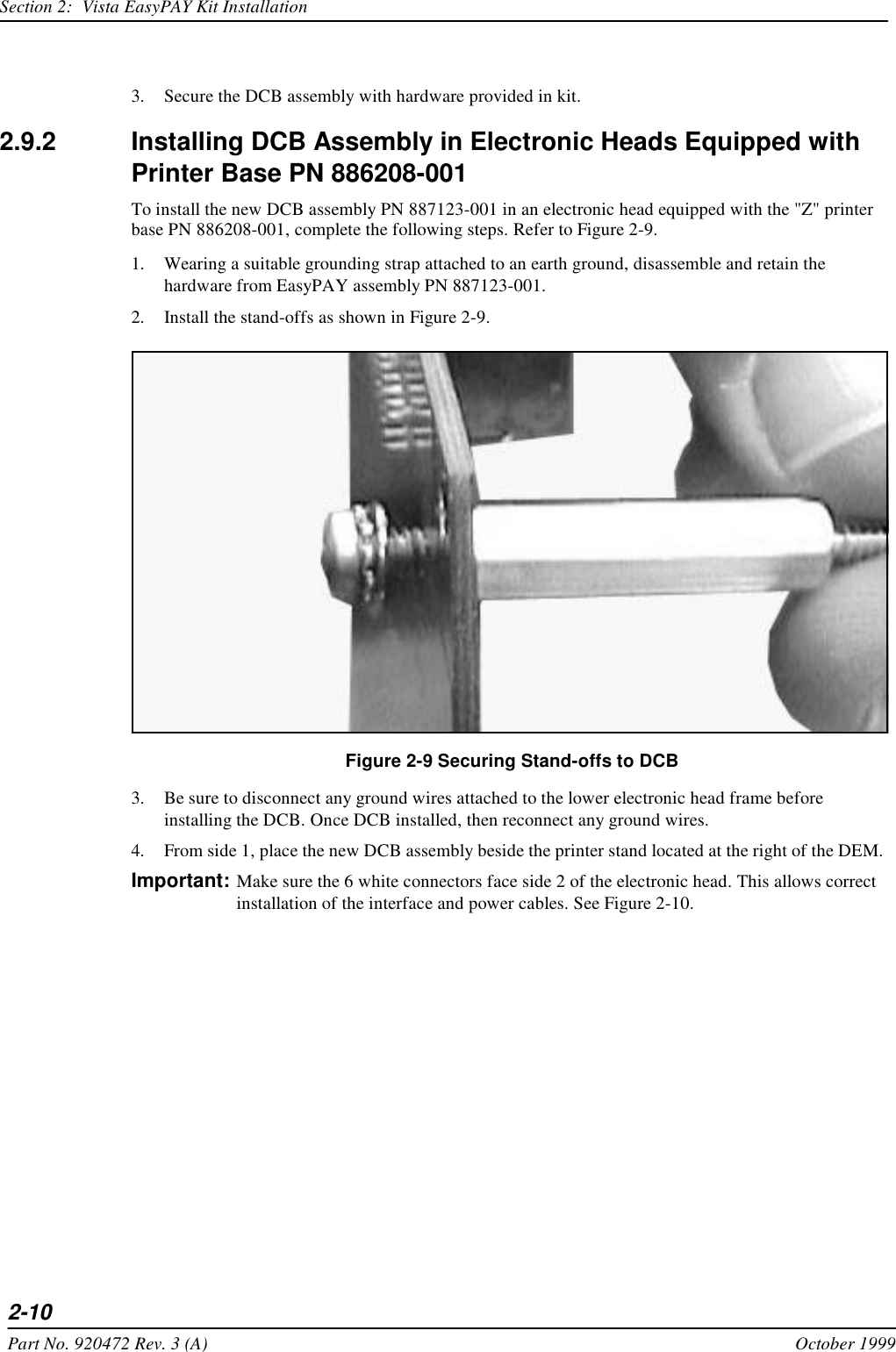
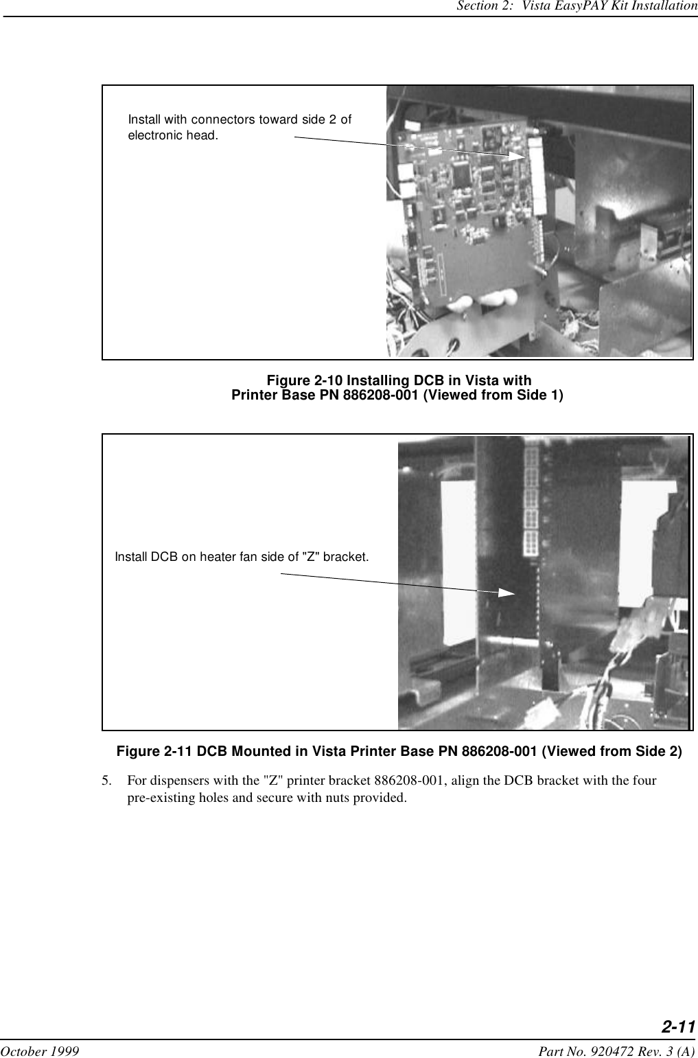
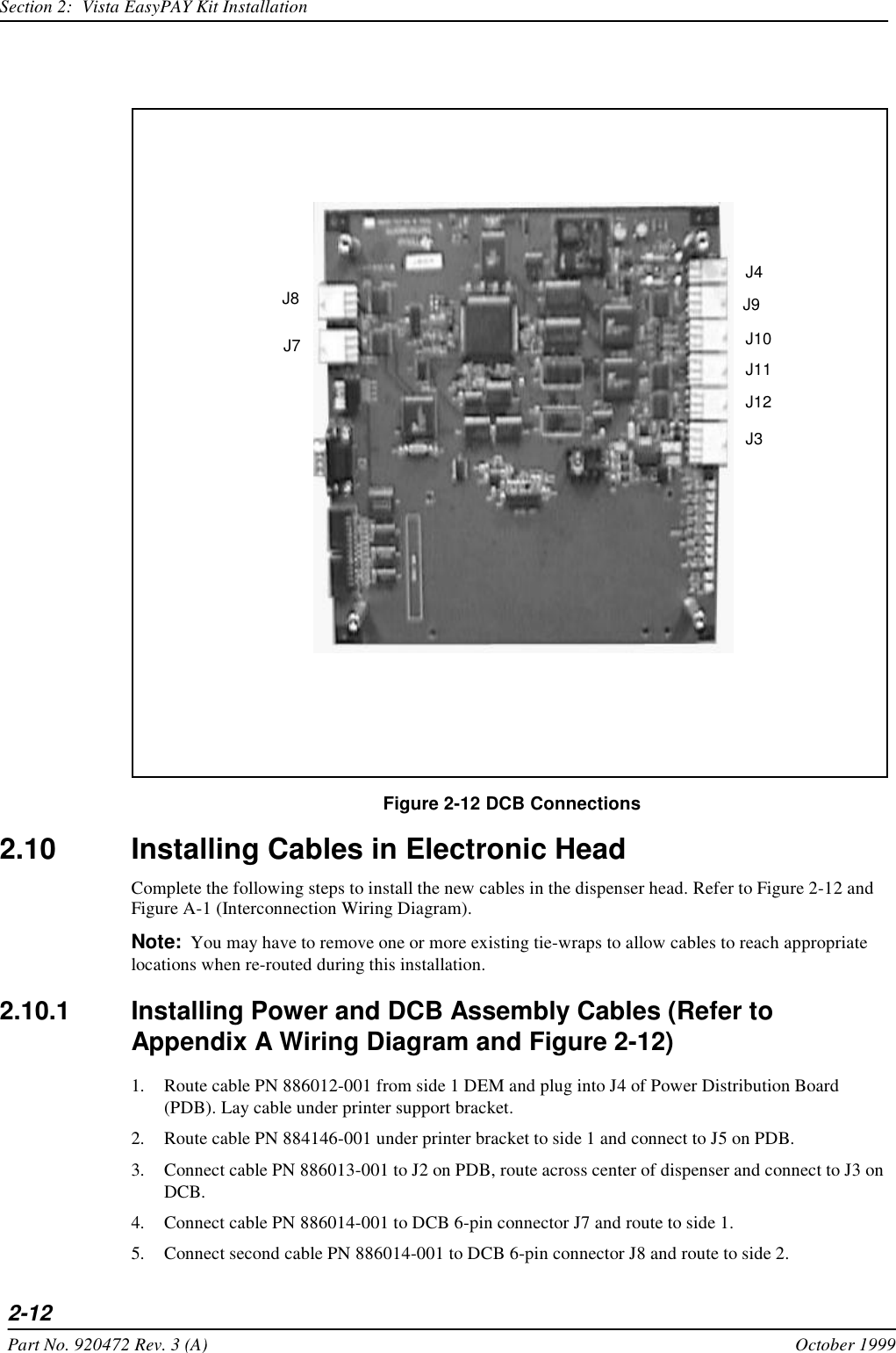
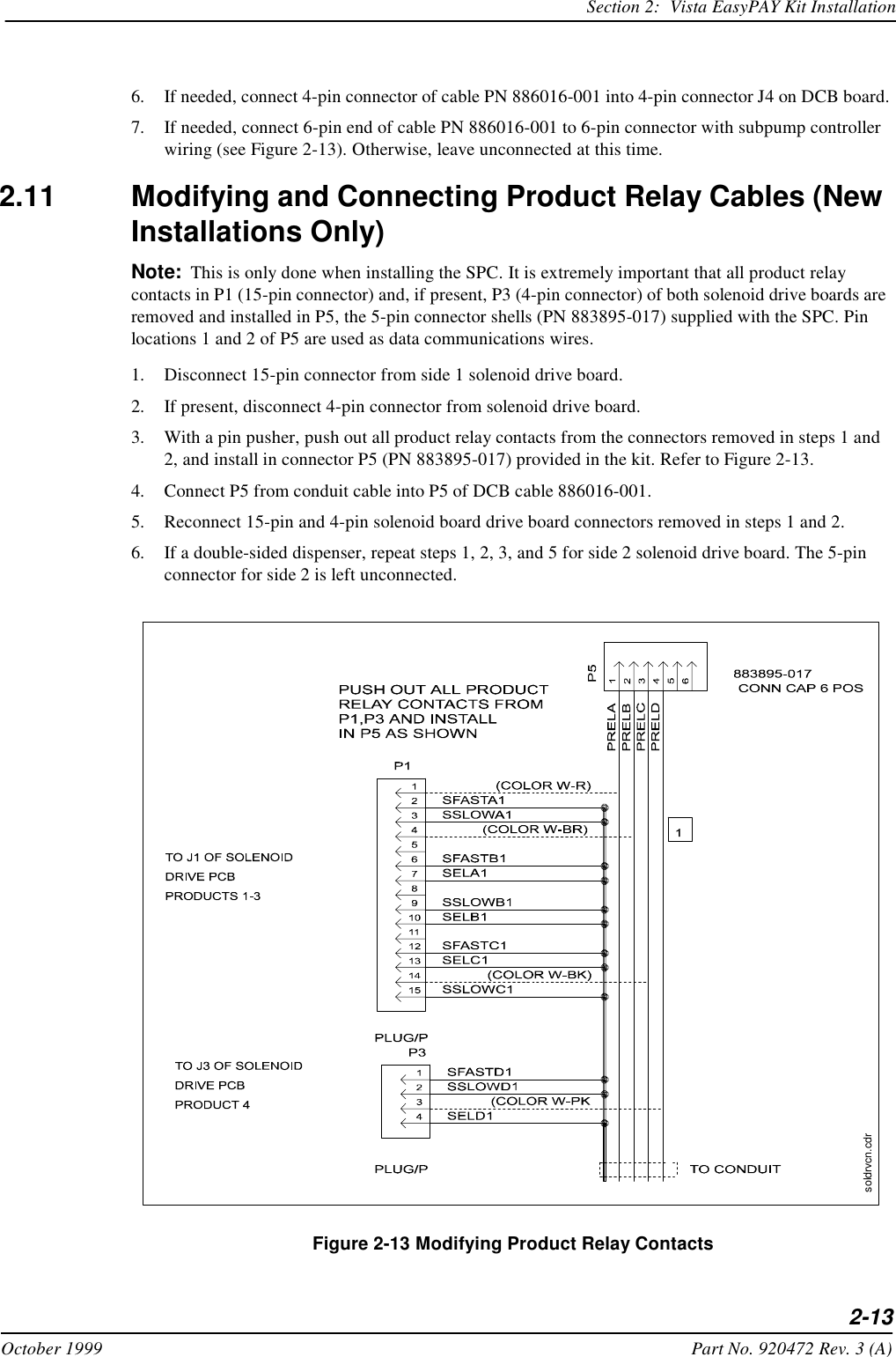
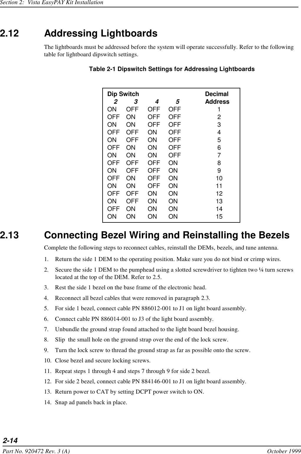
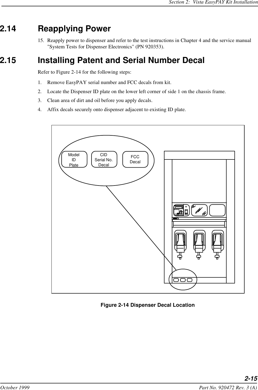
 vistaeasypay

Wayne Fueling Systems LLC vistaeasypay

installation manual

INSTALLATIONWayne EasyPAYTM for Vista Dispensers Preliminary Draft Limited DistributionWAYNELiftForReceipt
Installation ManualEasyPAYTM for Vista Dispensers
Copyright 1999 Dresser Industries, Inc.All rights reserved.Printed in the United States of AmericaEasyPay is a trademark of Wayne Division/Dresser Equipment Group, a Halliburton Company.No part of this publication may be electronically or mechanically reproduced, stored in a retrieval system, or transmitted, in any form or by any means without express written permission of Dresser Industries. Translation of this material to another language without express written permission of Dresser Industries is prohibited.The information in this publication is for informational use only and is subject to change without notice. The contents should not be construed as a commitment by Dresser Industries, Inc. who assumes no responsibility or liability for in-accuracies that may appear in this publication.Wayne Division / Dresser Industries, Inc.3814 Jarrett Way, Austin, TX  78728Telephone: (512) 388-8311Fax: (512) 388-8355
viiOctober 1999 Part No. 920472 Rev. 3 (A)Table of Contents1Before You StartIntroduction  1-1Unpacking and Inspection  1-2Returning Damaged Components  1-2Required Tools  1-3Power Ratings  1-32Vista EasyPAY Kit InstallationIntroduction  2-1Removing Dispenser Power  2-1Removing the Bezels  2-1Lowering the DEMs  2-3Installing the Authorization Light Assembly (PN887124)  2-4Relocating Wayne Vac Control Board  2-6Installing EMI Filter 2-7Installing Power Distribution Board  2-7Installing Power Supply Cables  2-8Installing the DCB (PN 887123-001) in Electronic Head  2-9Installing DCB Assembly in Electronic Heads Equipped with Printer Base PN 883727-001  2-9Installing DCB Assembly in Electronic Heads Equipped with Printer Base PN 886208-001  2-10Installing Cables in Electronic Head  2-12
viiiPart No. 920472 Rev. 3 (A) October 1999About This ManualInstalling Power and DCB Assembly Cables  2-12Modifying and Connecting Product Relay Cables (New Installations Only)  2-13Addressing Lightboards 2-14Connecting Bezel Wiring and Reinstalling the Bezels  2-14Reapplying Power  2-15Installing Patent and Serial Number Decal  2-15System Power-Up  2-163Subpump Controller InstallationIntroduction  3-1Power Rating  3-14System TestIntroduction  4-1Light Panel Functionality Test  4-1EasyPAY Functionality Test  4-2AWiring DiagramsIntroduction  A-1
viiOctober 1999 Part No. 920472 Rev. 3 (A)How To Use This ManualThis manual explains how to install the EasyPAY™ Vista retrofit. This includes Models V390, V395, V490, and V590. Important: By following this instruction manual from chapter 1 through chapter 4 in the sequences presented, you will be assured of a successful install. For best results, do not perform the steps out of the sequence shown.Section 1 includes unpacking and inspection procedures, component return procedures, and a list of tools required to install the retrofit kit. Section 2 provides instructions for installing the EasyPAY™ hardware in the dispenser head.Section 3 explains how to install the master installation kit. Section 4 shows how to test the EasyPAY™ hardware after installation.Appendix A includes interconnection wiring diagrams for the complete installation.
viiiPart No. 920472 Rev. 3 (A) October 1999About This Manual
1-1October 1999 Part No. 920472 Rev. 3 (A) Section     1Before You Start1.1 IntroductionThis manual explains how to install the EasyPAY™ retrofit kit in Wayne™ Vista 90 series dispensers. This includes Models V390, V395, V490, and V590. By following this instruction manual in the sequences presented, you will be assured of a successful in-stall. For best results, perform the steps in the sequence given for the particular kit or kits that are being installed. Important: These retrofit kits require installation of several wiring and hardware assemblies. Any installation or modification must comply with the requirements of the National Electrical Code (NFPA 70), the Automotive and Marine Service Station Code (NFPA 30A) and any other applicable codes. Refer to the information in Table 1-1 for identification of the EasyPAY™ retrofit kits.
1-2Part No. 920472 Rev. 3 (A) October 1999Section 1:  Before You StartImportant: You must wear a static wrist strap, part number 916962 or equivalent, securely attached to an earth ground, when handling any circuit board, electronic component or assembly, or when reaching into the site controller or dispenser computer enclosure. Do not use power tools.1.2 Unpacking and InspectionComplete the following steps:1. Before opening any cartons, count the number of cartons and verify the carton count against the supplied packing list.2. Inspect the cartons for damage made during transit.3. File claim information with the carrier on the bill of lading. 4. Retain cartons suspected of damage for future claim purposes. Caution: You must wear an anti-static wrist strap, part number 916962 when removing electronic components from static packages. Attach the wrist strap securely to an earth grounding point to prevent possible damage from static electricity. 5. Remove all equipment from the shipping cartons and carefully inspect for visible damage.Note: Any damage should be brought to the attention of the carrier and claims made immediately. Return all equipment to the respective cartons for protection until actual installation is made. Save all cartons until it is certain that return shipments are not required.6. Check supplied graphics (such as ad panel and dial face graphics) prior to start of installation. 1.3 Returning Damaged ComponentsParts or components returned to the factory under warranty or for repair are subject to damage if not pack-aged properly. Complete the following steps to return parts or components to the factory. 1. Place electronic components in an anti-static bag and in the original shipping cartons for return shipment to the factory. Note: If original shipping cartons are not available use a sturdy cardboard container and suitable packing materials such as anti-static polyethylene foam or bubble pack, to ensure the component is firmly packed. 2. Include a Return Parts Tag with the defective component describing the particular problem with the part. 3. Make sure adequate insurance is provided when returning parts to the factory.WARNING: If the parts or components arrive at our factory in a damaged condition and it is determined that the damage is a direct result of inadequate or improper packaging, the damage will not be covered under the original warranty and the customer or distributor will be held responsible for the cost of repairs necessary to correct or replace the damaged parts. Table 1-1 EasyPAY™ Retrofit Kits for Vista Part Number Description887122-001 EasyPAY Retrofit Kit, Vista DS
Section 1:  Before You Start1-3October 1999 Part No. 920472 Rev. 3 (A)1.4 Required ToolsRefer to Table 1-2 for a list of tools required to install the EasyPAY retrofit kit.1.5 Power RatingsThe EasyPAY installation does not change the existing dispenser power rating. Table 1-2 Required ToolsQuantity Description1Phillips Screwdriver (medium and small)1Slotted Screwdriver (medium and small)11/4 inch Nut Driver13/8 inch Socket Wrench1Diagonal Cutters1Anti-static Wrist Strap1Wire Stripper1Needle Nose Pliers1Pin Pusher
1-4Part No. 920472 Rev. 3 (A) October 1999Section 1:  Before You Start
2-1October 1999 Part No. 920472 Rev. 3 (A) Section     2Vista EasyPAY Kit Installation2.1 IntroductionThe information in this chapter explains how to install the EasyPAY retrofit kit (PN 887122-xxx). 2.2 Removing Dispenser PowerBefore you begin installing the retrofit kit, perform the following steps to protect the kit assemblies from damage. 1. Close station to fuel purchases.2. Disconnect the power from dispensers at the power panel. Post a warning sign at the power panel stating that the equipment is being serviced.2.3 Removing the BezelsComplete the following steps to remove the bezels from the dispenser.1. Remove and save any temporary advertisement or instructional attachments from the bezel face. 2. Place an anti-static wrist strap (PN 916962 or equivalent) on your wrist and attach the other end of the wrist strap to an earth grounding point.
2-2Part No. 920472 Rev. 3 (A) October 1999Section 2:  Vista EasyPAY Kit Installation3. Disengage the advertisement (ad) panels. Unsnap the ad panel by pulling forward firmly on the top edge of the panel. Refer to Figure 2-1. Figure 2-1 Removing the Ad Panel4. If necessary, unlock the function switch door.5. Turn the wing fasteners on the left and right side of bezel counter clockwise. Refer to Figure 2-2. Figure 2-2 Wing Fasteners on BezelWAYNEWayne1112323Tilt the ad panel out and down toward you.1/4 Turn Phillips Head ScrewsAd PanelBlank PanelDJR-FH/CD-1302ALift For ReceiptLift For ReceiptWAYNE2211334432PTS BarAreaAd Panel (lowered)Ad Panel FastenersWing FastenersFunction Switch Door LockDJR-CD-1303ALift For Receipt
Section 2:  Vista EasyPAY Kit Installation2-3October 1999 Part No. 920472 Rev. 3 (A)6. Rest the lower edge of the bezel on the dispenser and disconnect the following cables from the back of the bezel. a. If the bezel is equipped with a graphic display, disconnect the graphic display heater cable (PN 882827-001) plugged in the 2-conductor black connector that routes on the right side of the graphic display. See Figure 2-3. Figure 2-3 Disconnecting Cables on Back of Graphic Display Bezelb. Disconnect the cable assembly (PN 881524-xx) installed in J5 on the annunciator interface board. Refer to Figure 2-3 and Figure 2-4 for the following steps. c. If the bezel is equipped with a Push-to-Start (PTS) bar, disconnect the cable assembly (PN 881692-01 or 881693-01) plugged in the 13-pin connector on the back of the bezel.d. If the bezel is equipped with a CPM and a DES keypad, disconnect the cable assembly (PN 880963-02) plugged in the 4-pin connector on the DES keypad cable.e. If the bezel is equipped with KDC and a DES keypad is present, disconnect the cable assembly (PN 880963-01) plugged in the 4-pin DES keypad cable.f. If the dispenser is double-sided, repeat steps 3 through 6 to remove the bezel on the other side of the dispenser.2.4 Lowering the DEMsPerform the following steps to lower the DEM(s) (Display Electronic Modules) to the service position.1. Use a slotted screwdriver to loosen two ¼ turn screws located at the top of the DEM. Refer to Figure 2-4.2. Lower the DEM to the service position.3. Repeat steps 1 and 2 for the DEM on the other side of the dispenser.Rear View of CPM BezelJ3JP1J5DJR-FH/CD-1304AGraphic Display Adapter Board(Part No. 882440-xxx)DES Keypad4-Pin DES Keypad CableVista Annunciator InterfaceBoard (Part No. 883074-xx)
2-4Part No. 920472 Rev. 3 (A) October 1999Section 2:  Vista EasyPAY Kit Installation Figure 2-4 Lowering the DEM into the Service Position2.5 Installing the Authorization Light Assembly (PN887124)Complete the following steps to remove the blank panel from the bezel and install the authorization light assembly (PN 887124-xxx) in its place. Refer to Figure 2-5. 1. Locate the side 1 bezel removed earlier in paragraph 2.3.2. Use a ¼ inch nut driver to loosen and remove 3 hex head screws securing the blank panel to the back of the bezel. (See the following figure.) Set the blank panel aside. Retain the hardware for reinstallation later. DEM 1/4 Screws (2 Places)DispenserFront ViewSide 1 DEMServicePositionDispenserSide ViewDJR-FH/CD-1321A
Section 2:  Vista EasyPAY Kit Installation2-5October 1999 Part No. 920472 Rev. 3 (A) Figure 2-5 Removing the Blank Panels from the Vista Bezel3. Remove an authorization light assembly (PN 887124-001) from the retrofit kit.4. With the back of the authorization light panel facing toward you, install the device in the bezel. See Figure 2-6. Blank PanelBack View of BezelReceiving Slots(3 Places)Mounting Hardware(3 Places)Back View of BezelMounting Hardware(3 Places)Receiving Slots(3 Places)Removing the Blank Panel from the VistaCard BezelRemoving the Cash Access Door Panel from the VistaPay Bezelvistabks.cdr
2-6Part No. 920472 Rev. 3 (A) October 1999Section 2:  Vista EasyPAY Kit Installation Figure 2-6 Installing the Authorization Light Panel (PN 887124-001)5. Secure the authorization light bezel assembly to the bezel using the mounting hardware set aside in Step 2. Use a ¼ inch nut driver to tighten the hardware. 6. Install authorization side 2 light assembly PN 887124-001 by repeating steps 1 through 3 for the bezel on the other side of the dispenser. Skip step 4, then continue with steps 5 and 6.2.6 Relocating Wayne Vac Control BoardIf your electronic head is equipped with the old printer base PN 883727-001, you must relocate the Wayne Vac board. To relocate the Wayne Vac board, complete the following steps. 1. Disconnect and label all connectors on the side 1 Wayne Vac board.2. Remove the Wayne Vac board from its location on the side 1 printer base.3. Mount the Wayne Vac board onto the mounting bracket (PN 047585-xxx) using the plastic standoffs (PN 918642-000). 4. Repeat steps 1 through 3 for the side 2 Wayne Vac board.5. Align the Wayne Vac board bracket with the pre-existing holes in the frame next to the side 1 printer.6. Secure it with hardware provided to frame on both sides of the head.7. Reconnect all connectors removed earlier. Some re-routing of existing wires and harness may be necessary. Light PanelCover
Section 2:  Vista EasyPAY Kit Installation2-7October 1999 Part No. 920472 Rev. 3 (A)2.7 Installing EMI FilterPerfom the following steps to install the EMI filter.1. Disconnect three pin AC line input from EMI filter 881798-001 or 3-9974. This is the 10Amp EMI filter for the electronics. 2. Connect the three pin AC line input to the AC power cable assembly 887164-001, supplied with the kit. This is a “Y” expansion cable.3. Reconnect input of filter assembly 881798-001 or 3-997 with shortest end of the “Y” cable 887164-001.4. Using two 6/32 screws, connect the EasyPAY filter assembly  887173-001 to the filter bracket 886052-001.5. Mount this assembly to dispenser frame using existing holes located on either side of the side 2 DEM.6. Connect the input side of the filter assy (3 pin receptacle) to the remaining 3 pin plug of the “Y” expansion cable 887164-001.7. Disconnect the three-pin connector on cable 880560-XXX. This is the dual power supply AC input cable connecting to the power switch. 8. Connect filter cable plug (3pin) from EMI filter assembly 887173-001 to the three-pin receptacle of 880560-xxx that you just disconnected.2.8 Installing Power Distribution Board1. Disconnect cables (J1 and J3) from dual power supply on side 2 DEM.2. Loosen two retaining screws and raise front edge of power supply bracket.3. Install the PDB (PN 886038-001) and secure with hardware provided. See Figure 2-7.
2-8Part No. 920472 Rev. 3 (A) October 1999Section 2:  Vista EasyPAY Kit Installation Figure 2-7 Installing the Power Distribution Board (PDB)4. Return the power supply to the operation position after PDB is in place. 2.8.1 Installing Power Supply Cables 1. Connect cable PN 880586-001 to P1 on PDB.2. Connect P3 of cable PN 881984-002 to P3 on PDB.3. Connect cable PN 886011-001 from J1 on PDB to J1 on power supply board.4. Connect cable PN 886005-001 from J3 on the PDB to J3 on the power supply board.2.9 Installing the DCB (PN 887123-001) in Electronic HeadImportant: Before installing the DCB in the Vista dispenser, you must first identify the printer base. If the dispenser is equipped with printer base PN 883727-001, then you equip the dispenser with the EasyPAY assembly PN 887123-001shown in Figure 2-8. If the dispenser is equipped with a printer base PN 886208-001 then you must modify the assembly. To do so, refer to 2.9.2.Power SupplyBoardSide 2 DEMinstpdb.cdrPower DistributionBoard
Section 2:  Vista EasyPAY Kit Installation2-9October 1999 Part No. 920472 Rev. 3 (A)2.9.1 Installing DCB Assembly in Electronic Heads Equipped with Printer Base PN 883727-001If you are installing the DCB in a Vista with the "old" printer base PN 883727-001, refer to Figure 2-8. Figure 2-8 EasyPAY Assembly for Use With Old Printer Base PN 883727-0011. If there are any ground wires attached to the lower DCPT frame, be sure to disconnect them before installing the DCB assembly. Once the DCB is in place, then reconnect.2. Install the new DCB assembly such that it is facing the heater fan.
2-10Part No. 920472 Rev. 3 (A) October 1999Section 2:  Vista EasyPAY Kit Installation3. Secure the DCB assembly with hardware provided in kit.2.9.2 Installing DCB Assembly in Electronic Heads Equipped with Printer Base PN 886208-001To install the new DCB assembly PN 887123-001 in an electronic head equipped with the "Z" printer base PN 886208-001, complete the following steps. Refer to Figure 2-9.1. Wearing a suitable grounding strap attached to an earth ground, disassemble and retain the hardware from EasyPAY assembly PN 887123-001.2. Install the stand-offs as shown in Figure 2-9. Figure 2-9 Securing Stand-offs to DCB3. Be sure to disconnect any ground wires attached to the lower electronic head frame before installing the DCB. Once DCB installed, then reconnect any ground wires.4. From side 1, place the new DCB assembly beside the printer stand located at the right of the DEM. Important: Make sure the 6 white connectors face side 2 of the electronic head. This allows correct installation of the interface and power cables. See Figure 2-10.
Section 2:  Vista EasyPAY Kit Installation2-11October 1999 Part No. 920472 Rev. 3 (A) Figure 2-10 Installing DCB in Vista with Printer Base PN 886208-001 (Viewed from Side 1) Figure 2-11 DCB Mounted in Vista Printer Base PN 886208-001 (Viewed from Side 2)5. For dispensers with the "Z" printer bracket 886208-001, align the DCB bracket with the four pre-existing holes and secure with nuts provided.Install with connectors toward side 2 ofelectronic head.Install DCB on heater fan side of "Z" bracket.
2-12Part No. 920472 Rev. 3 (A) October 1999Section 2:  Vista EasyPAY Kit Installation Figure 2-12 DCB Connections2.10 Installing Cables in Electronic Head Complete the following steps to install the new cables in the dispenser head. Refer to Figure 2-12 and Figure A-1 (Interconnection Wiring Diagram).Note: You may have to remove one or more existing tie-wraps to allow cables to reach appropriate locations when re-routed during this installation.2.10.1 Installing Power and DCB Assembly Cables (Refer to Appendix A Wiring Diagram and Figure 2-12)1. Route cable PN 886012-001 from side 1 DEM and plug into J4 of Power Distribution Board (PDB). Lay cable under printer support bracket.2. Route cable PN 884146-001 under printer bracket to side 1 and connect to J5 on PDB.3. Connect cable PN 886013-001 to J2 on PDB, route across center of dispenser and connect to J3 on DCB.4. Connect cable PN 886014-001 to DCB 6-pin connector J7 and route to side 1.5. Connect second cable PN 886014-001 to DCB 6-pin connector J8 and route to side 2.J7J8J4J9J10J11J12J3
Section 2:  Vista EasyPAY Kit Installation2-13October 1999 Part No. 920472 Rev. 3 (A)6. If needed, connect 4-pin connector of cable PN 886016-001 into 4-pin connector J4 on DCB board.7. If needed, connect 6-pin end of cable PN 886016-001 to 6-pin connector with subpump controller wiring (see Figure 2-13). Otherwise, leave unconnected at this time.2.11 Modifying and Connecting Product Relay Cables (New Installations Only)Note: This is only done when installing the SPC. It is extremely important that all product relay contacts in P1 (15-pin connector) and, if present, P3 (4-pin connector) of both solenoid drive boards are removed and installed in P5, the 5-pin connector shells (PN 883895-017) supplied with the SPC. Pin locations 1 and 2 of P5 are used as data communications wires.1. Disconnect 15-pin connector from side 1 solenoid drive board.2. If present, disconnect 4-pin connector from solenoid drive board.3. With a pin pusher, push out all product relay contacts from the connectors removed in steps 1 and 2, and install in connector P5 (PN 883895-017) provided in the kit. Refer to Figure 2-13. 4. Connect P5 from conduit cable into P5 of DCB cable 886016-001. 5. Reconnect 15-pin and 4-pin solenoid board drive board connectors removed in steps 1 and 2.6. If a double-sided dispenser, repeat steps 1, 2, 3, and 5 for side 2 solenoid drive board. The 5-pin connector for side 2 is left unconnected. Figure 2-13 Modifying Product Relay Contactssoldrvcn.cdr
2-14Part No. 920472 Rev. 3 (A) October 1999Section 2:  Vista EasyPAY Kit Installation2.12 Addressing LightboardsThe lightboards must be addressed before the system will operate successfully. Refer to the following table for lightboard dipswitch settings. Table 2-1 Dipswitch Settings for Addressing Lightboards2.13 Connecting Bezel Wiring and Reinstalling the BezelsComplete the following steps to reconnect cables, reinstall the DEMs, bezels, and tune antenna.1. Return the side 1 DEM to the operating position. Make sure you do not bind or crimp wires.2. Secure the side 1 DEM to the pumphead using a slotted screwdriver to tighten two ¼ turn screws located at the top of the DEM. Refer to 2.5.3. Rest the side 1 bezel on the base frame of the electronic head.4. Reconnect all bezel cables that were removed in paragraph 2.3.5. For side 1 bezel, connect cable PN 886012-001 to J1 on light board assembly.6. Connect cable PN 886014-001 to J3 of the light board assembly.7. Unbundle the ground strap found attached to the light board bezel housing.8. Slip  the small hole on the ground strap over the end of the lock screw.9. Turn the lock screw to thread the ground strap as far as possible onto the screw.10. Close bezel and secure locking screws.11. Repeat steps 1 through 4 and steps 7 through 9 for side 2 bezel.12. For side 2 bezel, connect cable PN 884146-001 to J1 on light board assembly.13. Return power to CAT by setting DCPT power switch to ON.14. Snap ad panels back in place.Dip SwitchDecimal2 3 4 5AddressON OFF OFF OFF 1OFF ON OFF OFF 2ON ON OFF OFF 3OFF OFF ON OFF 4ON OFF ON OFF 5OFF ON ON OFF 6ON ON ON OFF 7OFF OFF OFF ON 8ON OFF OFF ON 9OFF ON OFF ON 10ON ON OFF ON 11OFF OFF ON ON 12ON OFF ON ON 13OFF ON ON ON 14ON ON ON ON 15
Section 2:  Vista EasyPAY Kit Installation2-15October 1999 Part No. 920472 Rev. 3 (A)2.14 Reapplying Power15. Reapply power to dispenser and refer to the test instructions in Chapter 4 and the service manual "System Tests for Dispenser Electronics" (PN 920353).2.15 Installing Patent and Serial Number DecalRefer to Figure 2-14 for the following steps:1. Remove EasyPAY serial number and FCC decals from kit.2. Locate the Dispenser ID plate on the lower left corner of side 1 on the chassis frame.3. Clean area of dirt and oil before you apply decals.4. Affix decals securely onto dispenser adjacent to existing ID plate. Figure 2-14 Dispenser Decal LocationModelIDPlateCIDSerial No.DecalFCCDecal
2-16Part No. 920472 Rev. 3 (A) October 1999Section 2:  Vista EasyPAY Kit Installation2.16 System Power-UpComplete the following steps.1. To add power to the dispensers, turn power ON at the control power circuit breaker.2. To turn power ON to the CAT, complete one of the following steps:a. For dual sided dispensers, turn power ON to the CAT at the function switch located on the side 2 DEM. b. For single sided dispensers, turn power ON to the CAT at the function switch located on the side 1 DEM. Note: If the CAT retrofit unit does not respond to power-up, check all connections. Replace any defective components.
3-1October 1999 Part No. 920472 Rev. 3 (A) Section     3Subpump Controller Installation3.1 IntroductionThe SPC is required for some EasyPAY installations. Those installations requiring you to convert two dispenser pump relay control wires to communication wires require SPC installation. One SPC, part number 884185-001, per site is required for those sites with converted wiring.Important:  You must refer to the manual entitled, “Wayne Sub Pump Controller for Nucleus,” part number 920474 for instructions for installing a a master kit with sub pump control. WARNING: Installing the master kit may expose you to high voltages that can be dangerous to you and station personnel. Do not attempt installation unless you are a licensed electrician.Note: The SPC requires installation of several wiring and hardware assemblies. Any installation or modification must comply with the requirements of the National Electrical Code (NFPA 70), the Automotive and Marine Service Station Code (NFPA 30A) and any other applicable codes. 3.2 Power RatingThe SPC installation does not change the existing power rating.
3-2Part No. 920472 Rev. 3 (A) October 1999Section 3:  Subpump Controller Installation
4-1October 1999 Part No. 920472 Rev. 3 (A) Section     4System Test4.1 IntroductionThe following paragraphs provide system test instructions for EasyPAY. Note: Refer to Service Manual PN 920353, “System Tests for  Electronic Heads” for testing CAT board, memory, card reader or display operations.4.2 Light Panel Functionality Test1. Open, but do not remove bezel or disconnect bezel wiring.2. Turn on DCPT power and make sure the red and yellow LEDs on the light board flash.3. If the LEDs flash, replace and secure the bezel.Note: If lights do not illuminate, check connections and inspect kit components for correct installation. Replace any defective components.
4-2Part No. 920472 Rev. 3 (A) October 1999Section 4:  System Test4.3 EasyPAY Functionality Test1. Hold transponder to area on bezel identified with the printed instructions.2. Light panel should illuminate and dispenser should authorize.If light panel fails to illuminate and dispenser authorization fails: a. Put the system in stand alone mode by placing jumper on JP1 on the addessed side of the bezels (usually side 1).b. Replace any defective components.c. If the light panel illuminates, the hardware is fine. There may still be a communication problem.d. If the light panel does not illuminate it usually means the light board or the antenna is bad.e. Check the lights on the DCB. Check to see that the heartbeat and the two 12 volt LED indicators and the TX and RX (transmit and receive) are flashing on the DCB.
A-1October 1999 Part No. 920472 Rev. 3 (A) Appendix    AWiring DiagramsRefer to the drawing on the following page for help in installing the EasyPAY Retrofit kit.
A-2Part No. 920472 Rev. 3 (A) October 1999Appendix A:  Wiring Diagrams
INSTALLATION MANUALEASYPAYTM VISTA, RETROFIT KIT Produced by Jim Hard.Artwork by Jim Hard and Karen Holland.Special thanks to Phong Cao, Lloyd Sargent, David Blanchard and Tom Sigmon.Very special thanks to Bart, BT, and the Rabbit.This manual was produced using Windows 95 and Framemaker 5 on a Wallingford Electronics PC.Page design uses a 1-column format set at 11/10 using Times New Roman and Arial.Mechanicals were printed on a Dataproducts LZR-2665 Typhoon 20 at 600 dpi then produced commercially.Art was produced using CorelDraw 7 for Windows 95.
WARRANTY AND LIMITATION OF REMEDY AND LIABILITYSeller warrants that new products and parts of its own design and manufacture when shipped, will be of goodquality and will be free from defects in material and workmanship and will conform to applicable specifications.Work, when performed by Seller, will meet applicable work requirements. No warranty is made with respect toused or rebuilt equipment and with respect to products not manufactured by Seller, Seller's only obligation shallbe to assign to Buyer, at the time of sale, whatever warranty Seller has received from the manufacturer. Itemssuch as but not limited to lamps, electric motors, hoses, nozzles, hose swivels and safety impact valves are in-cluded in the category referred to in the previous sentence. Seller's recommendations with respect to the oper-ation of Seller's equipment are advisory only and are not warranted. All claims under this warranty must bemade in writing immediately upon discovery and, in any event, with twelve (12) months from date of installa-tion, if a product is involved, or from completion of the applicable work, if work is involved, or fifteen (15)months from date of invoice (whichever shall occur first). (Provided however, that with respect to the Decade1000 electronic cash register, receipts/totals printer, and any other printers or printing mechanisms, all claimsmust be made in writing within ninety (90) days from date of installation.) Defective and nonconforming itemsmust be held for Seller's inspection and returned to the original f.o.b. point upon request. Seller's warranty onservice parts, whether new or reconditioned, is ninety (90) days from the date of installation, or twelve (12)months from date of invoice, whichever first occurs. THE FOREGOING IS EXPRESSLY IN LIEU OF ALLOTHER WARRANTIES WHATSOEVER, EXPRESSED, IMPLIED AND STATUTORY, INCLUDINGWITHOUT LIMITATIONS, THE IMPLIED WARRANTIES OF MERCHANTABILITY AND FITNESS.Upon Buyer's submission of a claim as provided above and its substantiation, Seller shall, at its option either (I)repair or replace its product or work at the original f.o.b. point or location of purchase products and/or parts or(II) refund an equitable portion of the purchase price. The foregoing is Seller's only obligation and Buyer's exclusive remedy for breach of warranty and, except forgross negligence, willful misconduct and remedies permitted under the performance inspection and acceptanceand the patents clauses hereof, the foregoing is Buyer's exclusive remedy against Seller for all claims arisinghereunder or relating hereto whether such claims are based on breach of contract, tort (including negligence andstrict liability) or other theories, Buyer's failure to submit a claim as provided above shall specifically waive allclaims for damages or other relief, including but not limited to claims based on latent defects. In no event shallbuyer be entitled to incidental or consequential damages. Any action by buyer arising hereunder or relatinghereto, whether based on breach of contract, tort (including negligence and strict liability) or other theories,must be commenced within one (1) year after the cause of action accrues or shall be barred.
"Note: This equipment has been tested and found to comply with the limits for a ClassA digital device, pursuant to Part 15 of the FCC Rules. These limits are designed toprovide reasonable protection against harmful interference when the equipment is op-erated in a commercial environment. This equipment generates, uses, and can radiateradio frequency energy and, if not installed and used in accordance with the instructionmanual, may cause harmful interference to radio communications. Operation of thisequipment in a residential area is likely to cause harmful interference in which case theuser will be required to correct the interference at his own expense."Wayne Division, Dresser Equipment Group,          3814 Jarrett Way Austin,             TX 78757 512/388-8311Part No. 920472 Rev. 3 (A)              10/99         1999 Dresser Equipment Group                         xxx10/99

Navigation menu