Webasto Thermo 90 St Users Manual Thermo_90S_90ST_en
2015-02-03
: Webasto Webasto-Thermo-90-St-Users-Manual-476724 webasto-thermo-90-st-users-manual-476724 webasto pdf
Open the PDF directly: View PDF ![]() .
.
Page Count: 55

Water heaters
08/2004
Workshop manual
Thermo 90 S
Thermo 90 S-ADR
(Transport of hazardous goods)
Thermo 90 ST
Thermo 90 ST-ADR
(Transport of hazardous goods)

Thermo 90 S / Thermo 90 ST Table of contents
I
Table of contents
1 Introduction
1.1 Contents and purpose ........................................................................................................................... 101
1.2 Meaning of signal words ........................................................................................................................ 101
1.3 Additional documentation to be used..................................................................................................... 101
1.4 Safety instructions and regulations........................................................................................................ 101
1.4.1 General safety regulations........................................................................................................... 101
1.5 Statutory regulations governing installation ............................................................................................102
1.6 Suggestions for improvements and modifications ................................................................................. 102
2 General description
2.1 Combustion air fan................................................................................................................................. 202
2.2 Heat exchanger ..................................................................................................................................... 202
2.3 Temperature sensor .............................................................................................................................. 203
2.4 Temperature limiter................................................................................................................................ 203
2.5 Burner insert .......................................................................................................................................... 203
2.6 Glow plug............................................................................................................................................... 203
2.7 Flame monitor........................................................................................................................................ 203
2.8 Combustion pipe.................................................................................................................................... 203
2.9 Circulating pump.................................................................................................................................... 203
2.10 Control unit ............................................................................................................................................ 203
2.11 Metering pump....................................................................................................................................... 203
3 Function description
3.1 Switching on .......................................................................................................................................... 301
3.2 Heating mode ........................................................................................................................................ 301
3.3 Control mode ......................................................................................................................................... 301
3.4 Switching off .......................................................................................................................................... 302
3.5 Heater functions when installed in ADR vehicles .................................................................................. 302
3.6 Malfunctions........................................................................................................................................... 303
3.6.1 Fault lock-out ............................................................................................................................... 303
3.6.2 Diagnosis after fault lock-out, Thermo 90 S and Thermo 90 ST ................................................. 304
4 Technical data ................................................................................................................................................ 401
5 Troubleshooting
5.1 General .................................................................................................................................................. 501
5.2 General fault indications ........................................................................................................................ 501
5.3 Fault indications on fault lock-out .......................................................................................................... 502
5.4 Visual check for assessing the burner ................................................................................................... 503
5.4.1 Burner housing .............................................................................................................................503
5.4.2 Back wall with metal evaporator .................................................................................................. 504
5.4.3 Combustion chamber .................................................................................................................. 504
5.4.4 Complete burner.......................................................................................................................... 504

Table of contents Thermo 90 S / Thermo 90 ST
II
6 Function tests
6.1 General ................................................................................................................................................. 601
6.2 Settings................................................................................................................................................. 601
6.2.1 Setting the CO2 content.............................................................................................................. 601
6.3 Testing individual components.............................................................................................................. 601
6.3.1 Resistance test of the temperature sensor ................................................................................. 601
6.3.2 Resistance test of the glow plug................................................................................................. 601
6.3.3 Resistance test of the flame monitor .......................................................................................... 601
6.3.4 Testing the combustion air fan.................................................................................................... 601
7 Circuit diagrams
7.1 General ................................................................................................................................................. 701
8 Service work
8.1 General ................................................................................................................................................. 801
8.2 Work on the heater ............................................................................................................................... 801
8.3 Work on the vehicle .............................................................................................................................. 801
8.4 Heater trial run ...................................................................................................................................... 802
8.5 Service work ......................................................................................................................................... 802
8.6 Visual inspections and installation instructions ..................................................................................... 804
8.6.1 Connection to the vehicle cooling system................................................................................... 804
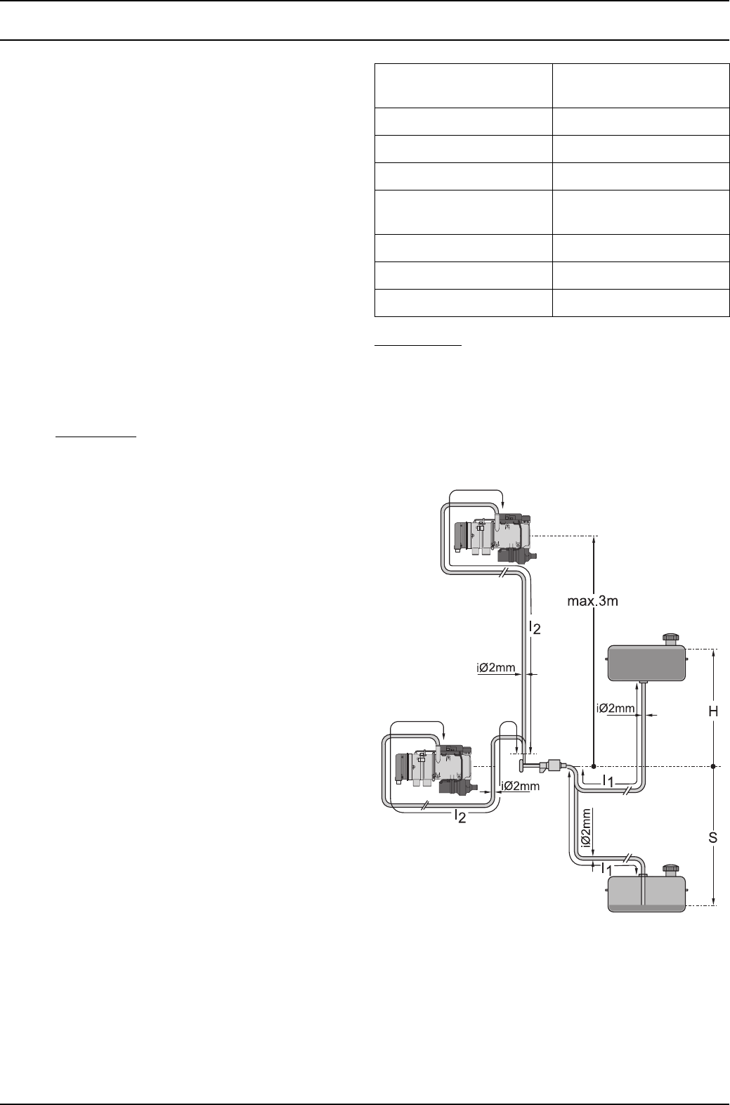
8.6.2 Connection to the vehicle fuel system ........................................................................................ 804
8.6.3 Metering pump with damper ....................................................................................................... 807
8.6.4 Fuel filter..................................................................................................................................... 807
8.6.5 Combustion air supply ................................................................................................................ 807
8.6.6 Exhaust line ................................................................................................................................ 808
8.7 Removal and installation....................................................................................................................... 808
8.7.1 Heater, removal and installation ................................................................................................. 808
8.7.2 Changing the circulating pump ................................................................................................... 809
8.7.3 Changing the temperature limiter ............................................................................................... 809
8.7.4 Changing the temperature sensor .............................................................................................. 809
8.7.5 Changing the combustion air fan................................................................................................ 809
8.8 Start-up ................................................................................................................................................. 809

Thermo 90 S / Thermo 90 ST Table of contents
III
9Repair
9.1 General .................................................................................................................................................. 901
9.1.1 Work on stripped-down components ........................................................................................... 901
9.2 Dismantling and assembling.................................................................................................................. 902
9.2.1 Electrical connections (Thermo 90 S).......................................................................................... 902
9.2.2 Changing the circulating pump .................................................................................................... 903
9.2.3 Changing the temperature limiter ................................................................................................ 904
9.2.4 Changing the temperature sensor ............................................................................................... 904
9.2.5 Changing the combustion air fan................................................................................................. 906
9.2.6 Changing the burner, flame monitor and glow plug..................................................................... 907
9.2.7 Changing the burner head........................................................................................................... 909
9.2.8 Changing the heat exchanger ..................................................................................................... 910
10 Packing, storage and shipment
10.1 General ................................................................................................................................................ 1001

List of illustrations Thermo 90 S / Thermo 90 ST
IV
List of illustrations
301 Sequence of functions ............................................................................................................................... 302
501 General fault indications ............................................................................................................................ 501
502 Fault indications on fault lock-out .............................................................................................................. 502
503 Visual check, burner back wall................................................................................................................... 503
504 Visual check, pilot flame outlet opening..................................................................................................... 504
505 Visual check, complete burner................................................................................................................... 504
701 System circuit for Thermo 90 S, 12 and 24 V, with standard clock............................................................ 702
702 System circuit for Thermo 90 S, 12 and 24 V, with standard clock and separate
circulating pump control ............................................................................................................................. 703
703 System circuit for Thermo 90 S-ADR, 24 V, with switch ............................................................................ 704
704 System circuit for Thermo 90 S-ADR, 24 V, with switch without power take-off ........................................ 705
705 System circuit for Thermo 90 ST, 12 and 24 V, with standard digital timer ............................................... 706
706 System circuit for Thermo 90 ST, 12 and 24 V, with standard digital timer and separate
circulating pump control ............................................................................................................................. 707
707 System circuit for Thermo 90 ST-ADR, 24 V, with switch.......................................................................... 708
708 System circuit for Thermo 90 ST-ADR, 24 V, with switch without power take-off...................................... 709
801 Specimen installations for heater in a truck ............................................................................................... 803
802 Fuel supply................................................................................................................................................. 804
803 Webasto fuel extractor............................................................................................................................... 805
804 Fuel extraction from the plastic tank (extraction through tank drain screw)............................................... 805
805 Fuel extraction from the plastic tank (extraction through tank fitting)......................................................... 805
806 Webasto fuel extractor............................................................................................................................... 806
807 Pipe/hose connection................................................................................................................................. 806
808 Metering pump, installation position and attachment ................................................................................ 807
809 Exhaust pipe opening, installation position................................................................................................ 808
901 Electrical connections (Thermo 90 S) ........................................................................................................ 902
902 Changing the circulating pump .................................................................................................................. 903
903 Changing the temperature limiter and temperature sensor ....................................................................... 905
904 Changing the combustion air fan ............................................................................................................... 906
905 Changing the burner, flame monitor and glow plug ................................................................................... 908
906 Changing the burner head ......................................................................................................................... 909

Thermo 90 S / Thermo 90 ST 1Introduction
101
1Introduction
1.1 Contents and purpose
This workshop manual is designed to assist trained
personnel with repairing both the petrol and the diesel
versions of the Thermo 90 S und Thermo 90 ST water
heaters.
The heater is only allowed to be operated with the
intended fuel (diesel or also with heating oil EL) and only
in the particular prescribed electrical connection type.
1.2 Meaning of signal words
Throughout this manual, the signal words WARNING,
CAUTION and NOTE have the following meanings:
WARNING
This heading is used to highlight operating instructions or
procedures which, if not or not correctly followed, may
result in personal injury or fatal accidents.
CAUTION
This heading is used to highlight operating instructions or
procedures which, if not or not correctly followed, may
result in damage to the equipment or its components.
NOTE
This heading is used to direct your attention to a special
feature deemed essential to highlight.
1.3 Additional documentation to be used
This workshop manual contains all necessary information
and instructions for repairing Thermo 90 S and Thermo 90 ST
water heaters.
Normally, there is no need to use additional
documentation.
If required, the installation instructions, the vehicle-
specific installation instructions and the operating
instructions can be used as well.
1.4 Safety instructions and regulations
In principle, the general accident prevention regulations
and current works safety instructions are applicable.
The “General safety regulations” that go beyond the
scope of the above regulations are stated below.
Any special safety regulations relevant to this instruction
manual will be highlighted in the relevant sections or text
passages of the procedures.
1.4.1 General safety regulations
The year of first start-up must be indelibly identified
on the rating plate by removing the corresponding
year number.
The heaters are only licensed for heating the motor
vehicle engine and vehicle cabin, not however for heating
the hazardous material transport space.
The heater is only allowed to be installed in motor vehicles
or in independent heating systems with a minimum
coolant volume of 6 litres.
The heater is not allowed to be installed in the driver’s cab
or passenger compartment of vehicles. If the heater is
nevertheless installed in such a place, the installation box
must be tightly sealed against the vehicle interior. The
installation box must have sufficient external ventilation to
ensure that a maximum temperature of 40 °C is not
exceeded in the box. Malfunctions may occur if the
temperature exceeds this level.
WARNING
The heater must not be operated in enclosed areas,
such as garages or workshops without an exhaust
emissions extraction system, not even using the
timer or Telestart, because of the risk of asphyxiation
and poisoning.
The heater must be switched off at filling stations and
fuel tank farms because of the risk of explosion.
CAUTION
Wherever inflammable vapours or dust may form (for
example near fuel, coal, wood dust or cereal stores or
the like), the heater must be switched off because of
the risk of explosion.
A temperature of 85 °C (storage temperature) must not be
exceeded in the vicinity of the control unit (for example
when completing painting work on the vehicle).
If this temperature is exceeded, the electronic systems
may suffer permanent damage.
Follow the instructions supplied by the vehicle
manufacturer to check the cooling water level. The water
in the heating circuit of the heater must contain at least
10% branded anti-freeze.
Non-compliance with the installation instructions and the
warnings contained therein will lead to the exclusion of all
liability by Webasto. The same applies if repairs are
carried out incorrectly or with the use of parts other than
genuine spare parts. This will result in the revocation of
the type licence for the heater and therefore the general
operating licence for the vehicle.

1Introduction Thermo 90 S / Thermo 90 ST
102
1.5 Statutory regulations governing
installation
Refer to the installation instructions for the statutory
regulations if necessary.
1.6 Suggestions for improvements and
modifications
Complaints, improvement suggestions or corrections
relating to this technical manual should be addressed to:
Webasto Thermosysteme International GmbH
Technical Documentation Dept.
D-82131 Stockdorf
Tel.: +49 (89) 8579 4542
Fax: +49 (89) 8579 4757
Thermo 90 S / Thermo 90 ST 2 General description
201
2 General description
Thermo 90 S and Thermo 90 ST water heaters operate in
conjunction with the vehicle’s own heating system and
serve
– to heat the cab,
– to defrost the vehicle windows and
– to preheat water-cooled engines.
The water heater operates independently of the engine
and is connected to the cooling system, the fuel system
and the electrical system of the vehicle.
The concept of the heater is based on the evaporator
principle. It is controlled by the temperature sensor and
operates intermittently.
Depending on the deviation between the current coolant
temperature and the nominal value measured at the
temperature sensor, the burner power is regulated
between the limits of 1.8 to 7.6 kW in diesel heaters and
1.8 to 7.6 kW in petrol heaters. When the heating
requirement is particularly high (preheating), diesel
heaters provide a maximum power of 9.1 kW for up to
2 hours after the heater is switched on.
The Thermo 90 S and Thermo 90 ST heater is principally
composed of
– the combustion air fan
– the heat exchanger
– the burner insert with combustion pipe
– the circulating pump
To control and monitor it, the heater has
– a control unit (external)
– a flame monitor
– a glow plug
– a temperature sensor
– a temperature limiter
inside it.
In the case of the Thermo 90 S heater, the control unit can
also be flange-mounted on the combustion air fan.
The Thermo 90 ST heater is delivered with the control unit
already flange-mounted on the combustion air fan.
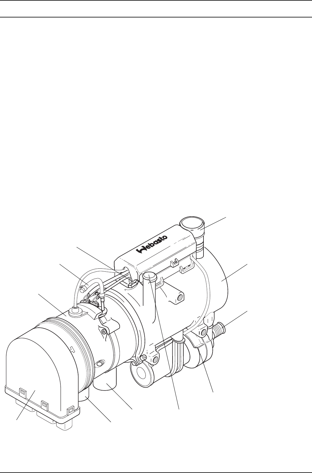
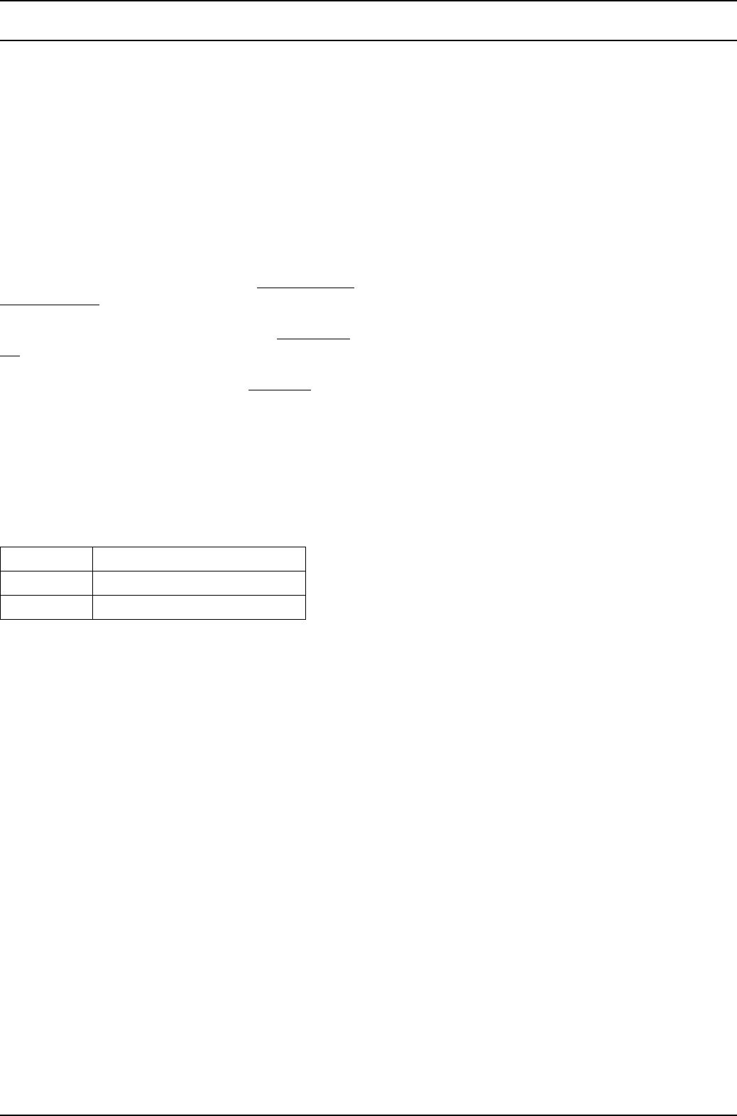
Thermo 90 S heater
Thermo 90 S
1
2
3
4
5
6
7
8
9
10
1 Combustion air fan
2 Fuel connection
3 Temperature sensor
4 Temperature limiter
5 Heat exchanger
6 Inlet, coolant
7 Circulating pump
8 Outlet, coolant
9 Outlet, exhaust gas
10 Inlet, combustion air
11 Control unit (can also be
arranged externally in the
vehicle)
11
2 General description Thermo 90 S / Thermo 90 ST
202
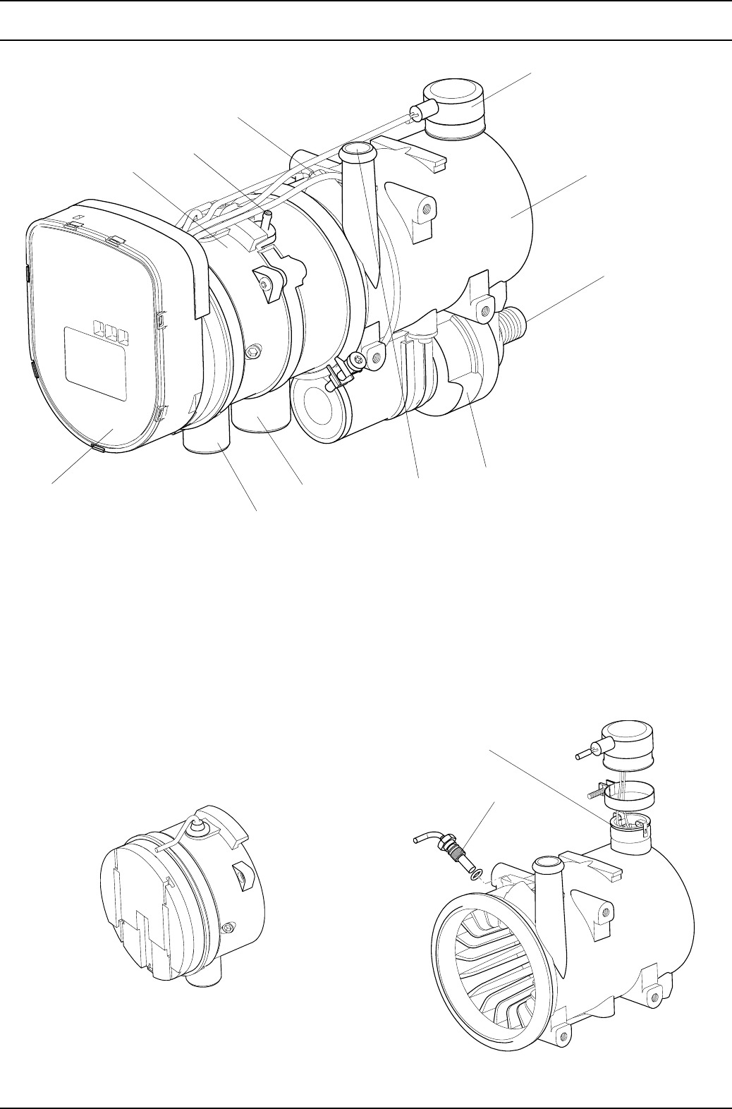
Thermo 90 ST heater
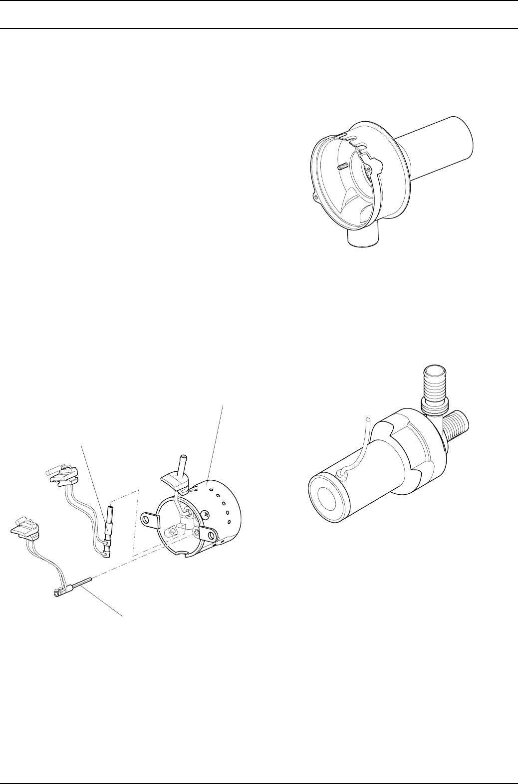
2.1 Combustion air fan
The combustion air fan supplies the air required for the
combustion process from the combustion air inlet to the
burner insert.
Combustion air fan
2.2 Heat exchanger
In the heat exchanger, the heat generated by combustion
is transferred to the coolant circuit.
Heat exchanger
1
2
3
4
5
6
7
8
9
10
11
1 Combustion air fan
2 Fuel connection
3 Temperature sensor
4 Temperature limiter
5 Heat exchanger
6 Inlet, coolant
7 Circulating pump
8 Outlet, coolant
9 Outlet, exhaust gas
10 Inlet, combustion air
11 Control unit
Temperature limiter
Temperature sensor
Thermo 90 S / Thermo 90 ST 2 General description
203
2.3 Temperature sensor
The temperature sensor records the coolant temperature
at the coolant outlet of the heater as an electrical
resistance. This signal is fed to the control unit where it is
processed.
2.4 Temperature limiter
The overheating guard circuit (bimetallic) protects the
heater against impermissibly high operating
temperatures. The overheating guard circuit trips if the
heat exchanger temperature exceeds 127 ±7 °C and
switches off the heater.
2.5 Burner insert
The fuel is distributed over the burner cross-section in the
combustion pipe in the burner insert.
2.6 Glow plug
The mixture of fuel and air is ignited by the glow plug when
the heater is started. The glow plug takes the form of an
electrical resistor and is positioned in the burner insert on
the side away from the flame.
2.7 Flame monitor
The flame monitor is a low-ohm PTC resistor, which
changes its resistance depending on the heat emitted by
the flame. The signals are fed to the control unit where
they are processed. The flame status is monitored by the
flame monitor whenever the heater is operating.
2.8 Combustion pipe
The mixture of fuel and air burns in the combustion pipe,
thus causing the heat exchanger to become hot.
Combustion pipe
2.9 Circulating pump
The circulating pump ensures that coolant is pumped
through the vehicle and heater circuits. The pump is
switched on by the control unit and it runs throughout
operation of the heater (including in the control pause).
Circulating pump
2.10 Control unit
The control unit is the central component. It guarantees
the sequence of functions and monitoring of combustion
mode. It is flange-mounted on the combustion air fan,
although in the case of the Thermo 90 S it may be
installed externally in the vehicle.
2.11 Metering pump
The fuel supply and metering for the heater is assured by
an external metering pump. It addition, it serves as a shut-
off element when the heater is switched off.
The solenoid coil of the metering pump receives its pulses
from the microprocessor in the control unit.
Burner insert
Glow plug
Flame monitor

2 General description Thermo 90 S / Thermo 90 ST
204
Page for notes

Thermo 90 S / Thermo 90 ST 3 Function description
301
3 Function description
(Fig. 301)
3.1 Switching on
The “operating indicator” on the digital timer lights up
when the “immediate heating” button is pressed.
or
When switching on with the switch, the operating indicator
in the switch lights up.
The circulating pump, glow plug and combustion air fan
start operating.
3.2 Heating mode
Combustion starts after approx. 60 to 140 seconds.
Automatically controlled heating operation runs at full load
for a maximum of 2 hours.
The vehicle’s own heater fan does not switch on until the
heat carrier (coolant) has heated up sufficiently. Once the
preset nominal temperature has been reached (see table
of regulating temperatures) the heating power is reduced
to the lowest part load in small individual steps.
3.3 Control mode
The heater switches to the control pause if the
temperature of the coolant continues to rise to the
threshold of the control pause. The circulating pump, the
vehicle’s own heater fan and the operating indicator
continue to operate during the control pause.
The heater restarts when the coolant cools to the preset
temperature for switching back on.
Diesel heaters
If the water temperature in the heater is higher than the
nominal temperature but has not yet reached the
threshold for the control pause and if the temperature then
falls back to the nominal temperature within 10 minutes
(after reaching this temperature for the first time), the
heater switches back to the 9.0 kW heating stage.
When the nominal temperature is reached, the heater is
only switched back on again up to the 7.6 kW heating
stage.
Petrol heaters
The maximum heating power in petrol heaters is
always 7.6 kW.
3 Function description Thermo 90 S / Thermo 90 ST
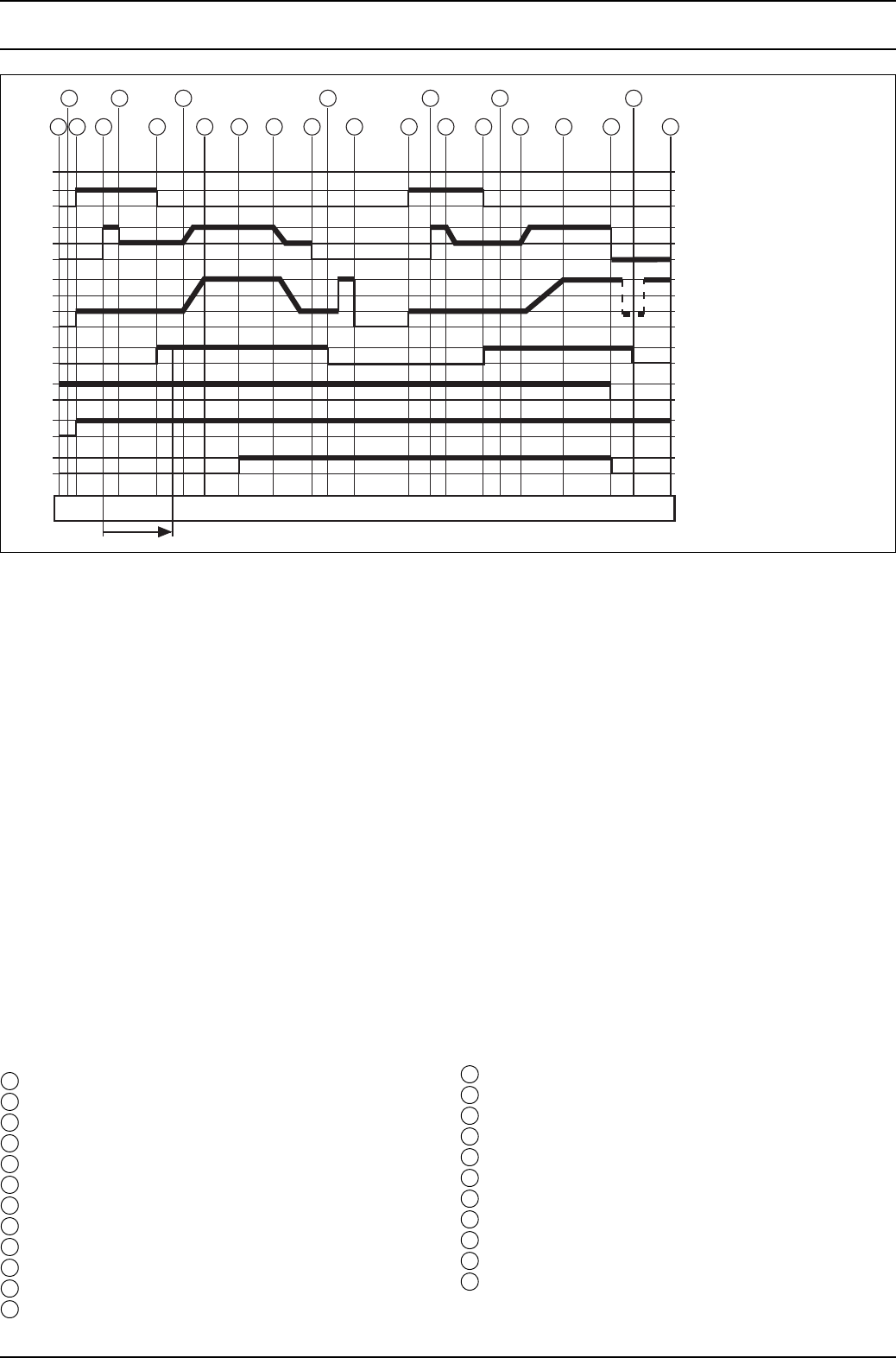
302
Fig. 301 Sequence of functions
3.4 Switching off
The operating indicator on the digital timer/switch goes
out when the heater is switched off. The combustion
process will be ended and the run-on phase will start.
The circulating pump and the combustion air fan continue
to run, however, in order to cool down the heater (run-on)
and are switched off automatically after approx.
105 seconds. The heater may be switched on again
during the run-on time.
The temperature in the cabin can also be controlled using
the vehicle’s own heater fan with a cabin thermostat.
3.5 Heater functions
when installed in ADR vehicles
The heater is started using the switch. An ADR case
(constrained shut-off) is triggered when
– the vehicle’s engine is switched off,
– a pumping device is started,
in which case the short run-on is terminated after
20 seconds (Thermo 90 S) and after 40 seconds
(Thermo 90 ST).
Following this, the control unit is left in the “fault lock-out”
status. The on/off switch must be moved to “Off” before it
can be restarted.
The disconnecting switch (emergency off switch) is only
allowed to be used in case of danger, because the heater
is switched off without any run-on (overheating possible).
Sequence of functions for Thermo 90 S and ST
Switch on
Component interrogation
Pre-glow 40 s (pulsed)
Metering pump supply 5 – 7 s (1)
Metering pump / part load (1/4)
Flame monitor take-over
Stabilisation time
Full load
Vehicle fan “On”
Control range
Control pause
Flame monitor “Cold” (0)
Run-on ended
Pre-glow 15 – 20 s (pulsed)
Metering pump supply 5 – 7 s (1)
Metering pump / part load (1/4)
Flame monitor take-over
Stabilisation time
Coolant temperature reduced
Full load
Switch off (run-on)
Flame monitor “Cold” (0)
Run-on ended
A
B
C
D
E
F
G
1
0
1
0
0
0
0
0
0
1
1
1
1
1
1/4
1/2
1/4
*
30 80 90 75 70 °C
23
22
212019171614131110
181512
986431
2 5 7
Safety time
❏
*If no flame is formed, the
start is automatically
repeated (20 s pulse pre-
glow, 90 s safety time).
oPossible regulating
temperatures that can be
set, see table below
1
2
3
4
5
6
7
8
9
10
11
12
13
14
15
16
17
18
19
20
21
22
23
Thermo 90 S / Thermo 90 ST 3 Function description
303
A Glow plug
B Metering pump
C Combustion air fan
D Flame monitor
E Operation indicator light
F Circulating pump
G Vehicle fan
3.6 Malfunctions
3.6.1 Fault lock-out
Fuel is supplied for max. 240 seconds if the flame does
not start to burn.
Fuel is supplied for max. 240 seconds if the flame goes
out during operation.
The fuel supply is shut off if the system overheats
(temperature limiter is tripped). If the system overheats,
the button on the temperature limiter must be reset.
Once the cause of the fault has been eliminated, the fault
lock-out is cancelled by switching the heater off and on
again.
If the undervoltage guard switches off the system
for longer than 20 seconds, the fuel supply is interrupted.
CAUTION
A forced reset of the return spring when hot can result in
damage to the component.
Thermo 90 S and Thermo 90 ST
12 volts 10.5 V - 0.5 V
24 volts 21 V -1 V

3 Function description Thermo 90 S / Thermo 90 ST
304
3.6.2 Diagnosis after fault lock-out
Thermo 90 S and Thermo 90 ST
Check the fuses and plug connectors.
3.6.2.1 Version with digital timer
If the system is equipped with a standard clock, a fault
message appears on the display of the digital timer after
a fault occurs:
F 01 No start (after 2 attempts to start)
F 02 Flame failure
F 03 Undervoltage or overvoltage
F 04 Premature flame recognition
F 05 Flame monitor interrupt or flame monitor short
circuit
F 06 Temperature sensor interrupt or temperature
sensor short circuit
F 07 Metering pump interrupt or metering pump short
circuit
F 08 Fan motor interrupt or fan motor short circuit or
fan motor incorrect speed
F 09 Glow plug interrupt or glow plug short circuit
F10 Overheating
F 11 Circulating pump interrupt or circulating pump
short circuit
3.6.2.2 Version with switch
If the system is operated with a switch, the nature of the
fault is indicated by a flashing code on an operating
indicator light during the run-on time of the heater.
After five short signals, count the long flashes:
1x No start (after 2 attempts to start)
2x Flame failure
3x Undervoltage or overvoltage
4x Premature flame recognition
5x Flame monitor interrupt or flame monitor short
circuit
6x Temperature sensor interrupt or temperature
sensor short circuit
7x Metering pump interrupt or metering pump short
circuit
8x Fan motor interrupt or fan motor short circuit or fan
motor incorrect speed
9x Glow plug interrupt or glow plug short circuit
10x Overheating
11x Circulating pump interrupt or circulating pump short
circuit

Thermo 90 S / Thermo 90 ST 3 Function description
305
Page for notes

Thermo 90 S / Thermo 90 ST 4 Technical data
401
4 Technical data
Except where limit values are specified, the technical data
below refer to the usual heater tolerances of ±10% at an
ambient temperature of +20 °C and at the rated voltage.
Electrical components
The control unit, motors for combustion air fan and
circulating pump, glow plug, switch and digital timer (no
timer for ADR mode) are designed for either 12 volts or
24 volts.
The temperature limiter, temperature sensor and flame
monitor are identical on 12 V and 24 V heaters.
Fuel for Thermo 90 S / Thermo 90 ST petrol:
The fuel specified by the manufacturer must be used.
Both leaded and unleaded fuel may be used.
Fuel for Thermo 90 S / Thermo 90 ST and Thermo 90
S-ADR / Thermo 90 ST-ADR (diesel):
The diesel fuel specified by the manufacturer must be
used.
We know of no negative influences due to additives. If fuel
is extracted from the vehicle’s tank, follow the additive
instructions issued by the vehicle manufacturer.
If you change to low-temperature fuel, the heater must be
operated for approx. 15 minutes so that the fuel line and
fuel pump are filled with the new fuel.
Heater Operation Thermo 90 S
Petrol
Thermo 90 ST
Petrol
Thermo 90 S diesel
Thermo 90 S-ADR
Thermo 90 ST diesel
Thermo 90 ST-ADR
EC licensing symbol ~S299 ~S298
Model Water heater with Ferro-Tec technology
Heat output Max.
regulating
range
2.0 kW – 7.6 kW
9.1 kW
1.8 kW – 7.6 kW
Fuel Petrol Diesel
Fuel consumption Max.
regulating
range
0.25 l/h – 1.0 l/h
1.1 l/h
0.19 l/h – 0.9 l/h
Rated voltage 12 volts 12 or 24 volts
Operating voltage range 10 ... 15 volts 10 ... 15 or 20 ... 30 volts
Nominal power consumption with circulating
pump
(without vehicle fan)
Max.
regulating
range
37 W – 83 W
90 W
37 W – 83 W
Max. ambient temperature:
Heater: - Operation -40 ... +110 °C (90 °C with control unit installed on heater)
- Storage -40 ... +110 °C (90 °C with control unit installed on heater)
Control unit: - Operation -40 ... +75 °C -40 ... +85 °C -40 ... +75 °C -40 ... +85 °C
- Storage -40 ... +85 °C
Metering pump: - Operation -40 ... +20 °C -40 ... +40 °C
- Storage -40 ... +85 °C
Permitted operating pressure (heat carrier) Max. 2.0 bar
Capacity of the heat exchanger 0.15 l
Max. combustion air intake temperature +40 °C
Minimum capacity of the circuit 6.00 l
Delivery rate of the circulating pump
against 0.15 bar
1650 l/h
CO2 in exhaust fumes (permitted function
range)
Max. 10 ... 12.0% by volume
CO2 adjustment values at approx. +20 °C
and geographic altitude above sea level
Max. 0 m 500 m 1000 m
10% 10.6% 11.3%
Heater dimensions (tolerance ± 3 mm)
* Control unit installed on the heater
L 310 (355*) mm
W 131 mm
H 232 mm
L 307 (352*) mm
W 131 mm
H 232 mm
L 310 (355*) mm
W 131 mm
H 232 mm
L 307 (352*) mm
W 131 mm
H 232 mm
Weight 4.8 kg

4 Technical data Thermo 90 S / Thermo 90 ST
402
Page for notes

Thermo 90 S / Thermo 90 ST 5 Troubleshooting
501
5 Troubleshooting
5.1 General
This section describes how to identify and remedy faults
on the Thermo 90 S und Thermo 90 ST heater.
CAUTION
Troubleshooting work demands precise knowledge of the
structure and theory of operation of the various
components and must be carried out by trained personnel
only.
If in doubt, refer to sections 2 and 3 for a description of
how the functions interact.
CAUTION
As a rule, fault detection is restricted to the localisation of
defective components.
The following potential sources of malfunctions are not
taken into account and should always be checked so that
they can then be excluded as the cause of the particular
fault:
• Corroded plugs
• Loose plug contacts
• Poor crimp contacts on plugs
• Corroded cables and fuses
• Corroded battery terminals
• Impermissibly high ambient temperature
Conduct a function test in the vehicle after rectifying each
fault; switch the heater off and back on again first.
5.2 General fault indications
The following table (Fig. 501) lists the possible general
fault indications.
Fig. 501 General fault indications
NOTE
In many cases, the burner may be one possible cause.
Perform a visual check in accordance with 5.4.
Fault indication Possible cause Remedy
Heater switches off
automatically
No combustion after start and
restart
Control unit enters fault lock-out status.
Switch the heater off and back on again.
Flame extinguishes during
operation
Contact a Webasto service centre if heater
operation does not start again
Heater overheats due to lack/
loss of coolant
Top up coolant.
After the unit has cooled down, press the
button of the temperature limiter before
switching on or fit a new temperature limiter
Voltage failure
longer than 20 seconds
Check fuses, plug connectors and charge
condition of the battery
Switch off by temperature limiter After the unit has cooled down,
press the button of the temperature limiter
before switching on or fit a new temperature
limiter
No flame recognition on start Check flame monitor and connections

5 Troubleshooting Thermo 90 S / Thermo 90 ST
502
5.3 Fault indications on fault lock-out
NOTE
If the system is operated with a switch, the nature of the
fault is indicated by a flashing code on an indicator light
during the run-on time of the heater.
After five short signals, count the long flashes.
In the Thermo 90 S heater with a standard clock, the fault
is output on the clock display (see 3.6.3). The following
table can be used accordingly.
Fig. 502 Fault indications on fault lock-out (page 1 of 2)
Fault indication Possible cause Remedy
No function Electrical cabling,
fuses
Check fuses
Check battery connections:
+ on 12 / – on 9 / + on 3, plug X12
(Thermo 90 S)
+ on 12 / – on 9 / + on 3, plug X8
(Thermo 90 ST)
Control unit defective Replace control unit
1 Flashing pulse
(start did not occur)
Fuel system Check fuel level
Check fuel filter
Bleed fuel system
Combustion air/exhaust line Check combustion air/exhaust line for
foreign bodies and clean if necessary
Burner Clean burner and change if necessary
2 Flashing pulses
(flame failure during burner
operation)
Fuel supply Check fuel level
Check fuel filter
Bleed fuel system
Burner Clean burner and change if necessary
3 Flashing pulses
(undervoltage)
Electrical power supply Check battery
Check electrical connections
4 Flashing pulses
(flame monitor continuously
hot)
Flame monitor defective Replace flame monitor
5 Flashing pulses
(flame monitor defective)
Cabling Check cabling for damage, discontinuity and
short-circuit
Flame monitor defective Replace flame monitor
6 Flashing pulses
(temperature sensor
defective)
Cabling Check cabling for damage, discontinuity and
short-circuit
Temperature sensor defective Replace temperature sensor
7 Flashing pulses
(metering pump defective/
(overheating guard circuit
defective)
Coolant circuit Check coolant level
Bleed coolant circuit
Reset temperature limiter
Cabling Check cabling for damage, discontinuity and
short-circuit
Metering pump defective Replace metering pump
8 Flashing pulses
(combustion air fan
defective)
Cabling Check cabling for damage, discontinuity and
short-circuit
Combustion air fan defective Replace combustion air fan
Thermo 90 S / Thermo 90 ST 5 Troubleshooting
503
Fig. 502 Fault indications on fault lock-out (page 2 of 2)
5.4 Visual check for assessing
the burner
The burner and the evaporator in the heater display
specific characteristics when they must be replaced or do
not have any fault source.
The criteria of a correct check are listed below.
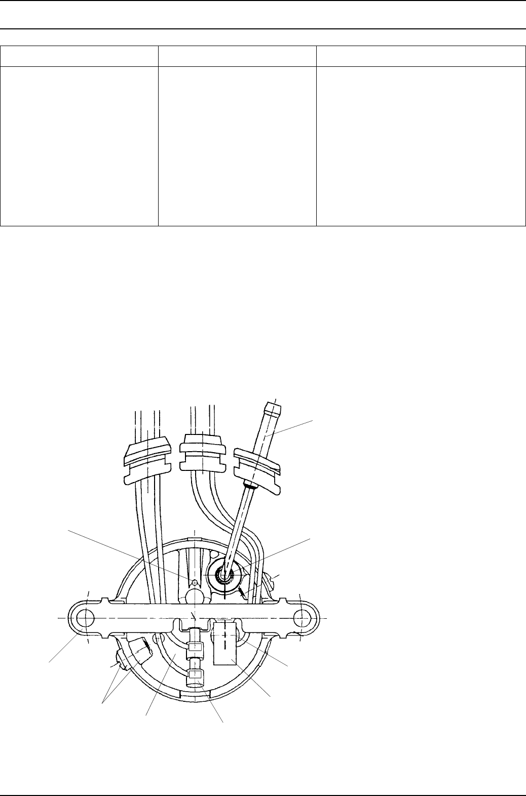
5.4.1 Burner housing
• The start air hole (Fig. 503) must be clear otherwise
no start will occur.
Remedy
Carefully remove impurities from the start air hole
(e.g. using a 1.5 mm diameter wire). Remove the glow
plug first.
Fig. 503 Visual check, burner back wall
Fault indication Possible cause Remedy
9 Flashing pulses
(glow plug defective)
Cabling Check cabling for damage, discontinuity and
short-circuit
Flow plug defective Replace glow plug
10 Flashing pulses
(overheating)
Heater overheats Check coolant and top up if necessary.
After the unit has cooled down, press the
button of the temperature limiter before
switching on or fit a new temperature limiter
11 Flashing pulses
(circulating pump defective)
Cabling Check cabling for damage, discontinuity and
short-circuit
Circulating pump defective Replace circulating pump
1 Fuel pipe
2 Round seal
3Flame monitor
4 Insulation
5 Glow plug
6Housing
7Screw
8Bar
9 Start air hole
1
2
3
4
5
6
7
8
9
5 Troubleshooting Thermo 90 S / Thermo 90 ST
504
5.4.2 Back wall with metal evaporator
• The pilot flame outlet opening (Fig. 504) must be clear
otherwise no start will occur.
Remedy
Replace burner
• Cracks, flaking as well as black or other discoloration
of the evaporator do not lead to burner failure and are
not significant.
• Coke deposits on the evaporator surface (except for
the pilot flame outlet opening) are normal; as a rule,
the burner cleans itself due to the load changes from
full load to part load and part load to full load.
Fig. 504 Visual check, pilot flame outlet opening
5.4.3 Combustion chamber
• The combustion chamber (Fig. 505) should not be
damaged (e.g. dented). A dented combustion
chamber can lead to poor combustion or carbon build-
up in the heater.
Remedy
Replace burner
• The air holes (Fig. 505) in the combustion chamber
must not be blocked up by carbon deposits. If the air
holes are blocked up by carbon deposits, this may
result in failure of combustion to start or to run
effectively.
Remedy
Carefully scratch clear the air holes
5.4.4 Complete burner
• The cables of the glow plug and flame monitor must
be routed as shown in Fig. 503.
• The screw connection of the housing and combustion
chamber (Fig. 505) must be tight.
• The housing and the combustion chamber (Fig. 505)
must be firmly connected together and there must not
be any play (check by moving the fuel pipe slightly).
• The round sealing ring (Fig. 503) must evenly
surround the fuel pipe and must not leak.
• The distance (gap) between the edge of the housing
and the top edge of the combustion chamber
(Fig. 505) does not have to be even all the way
around.
• The insulation (Fig. 503) must not be missing.
Fig. 505 Visual check, complete burner
Pilot flame outlet opening
Metal evaporator, petrol
Pilot flame outlet opening
Metal evaporator, diesel
Combustion chamber Swirl orifice
Air holes
Gap between housing
and combustion chamber

Thermo 90 S / Thermo 90 ST 6 Function tests
601
6 Function tests
6.1 General
This section describes the tests conducted on the heater
and its settings when it is installed and not installed to
verify that it is in working order.
WARNING
The heater must not be operated in enclosed areas such
as garages and workshops without an emissions
extraction system.
6.2 Settings
6.2.1 Setting the CO2 content
It is permitted for the factory-set combustion air quantity to
be modified. This is achieved by turning the air regulating
screw.
Setting procedure
Turning clockwise: CO2 value is reduced (let the heater
run for about 5 minutes before measuring).
Rough setting: Screw the adjusting screw fully in
clockwise and then one turn back.
6.3 Testing individual components
6.3.1 Resistance test of the temperature sensor
If you conduct this electrical test with a digital multimeter,
the temperature sensor should have the following values
at room temperature:
Resistance at 25 °C: 990 ... 1010 Ω
Test current: < 1 mA
6.3.2 Resistance test of the glow plug
If you conduct this electrical test with a digital multimeter,
the glow plug should have the following values:
Glow plug: 12 volts (red) 24 volts
(green)
Resistance at 25 °C: 0.3 ... 0.6 Ω1.3 ... 1.44 Ω
Test current: < 5 mA < 5 mA
6.3.3 Resistance test on the flame monitor
If you conduct this electrical test with a digital multimeter,
the flame monitor should have the following values:
Cold test:
Resistance at 25 °C: 3.0 ±0.4 Ω
Test current: < 5 mA
Hot test:
Resistance at 800 ±20 °C: 8 ±1.0 Ω
(ceramic rod at red heat over length of approx. 20 mm)
Test current: < 5 mA
6.3.4 Testing the combustion air fan
The motor speed test must be performed with the heater
assembled and in the operating voltage range. Listen out
for grinding noises.
NOTE
The cover must be removed from the fan in order to check
the motor speed. Fit a new seal before re-installing.
CAUTION
Make sure the detent lugs do not break off.
Fit a new cover and a new seal if the detent lugs have
broken off.
Speed in control range min. 1800 rpm (±9%)
Speed in control range max. 5600 rpm (±9%)
Fit a new combustion air fan if the speeds are outside
tolerance (see 9.2.5).

6 Function tests Thermo 90 S / Thermo 90 ST
602
Page for notes

Thermo 90 S / Thermo 90 ST 7 Circuit diagrams
701
7 Circuit diagrams
7.1 General
The circuit diagrams (Figs. 701 to 704) show the possible
circuits for the Thermo 90 S heater with
– Standard clock
– Standard clock and separate circulating pump
control
– ADR and switch
– ADR and switch, without power take-off
The circuit diagrams (Figs. 705 to 708) show the possible
circuits for the Thermo 90 ST heater with
– Standard clock
– Standard clock and separate circulating pump
control
– ADR and switch
– ADR and switch, without power take-off
7 Circuit diagrams Thermo 90 S / Thermo 90 ST
702
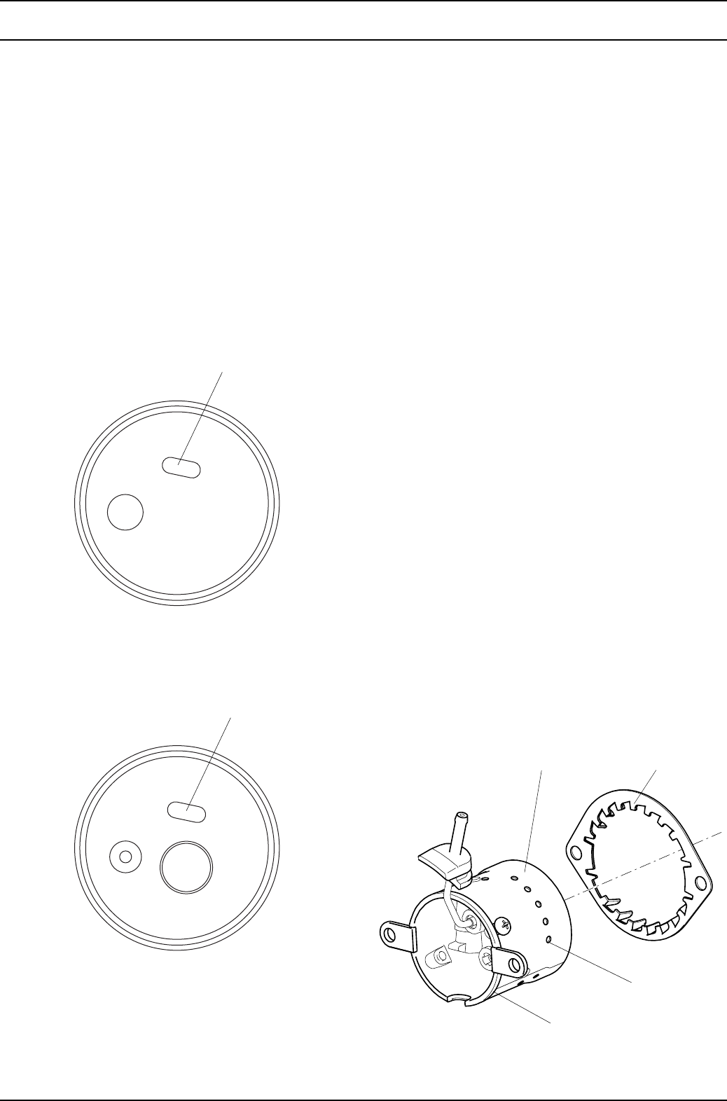
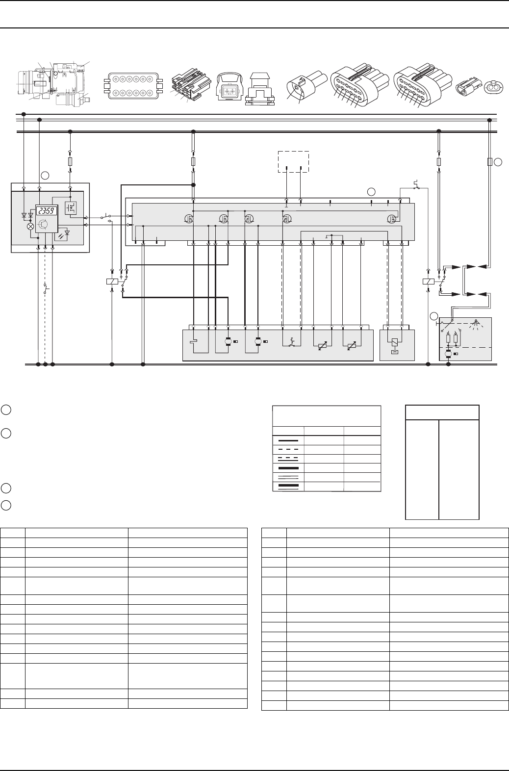
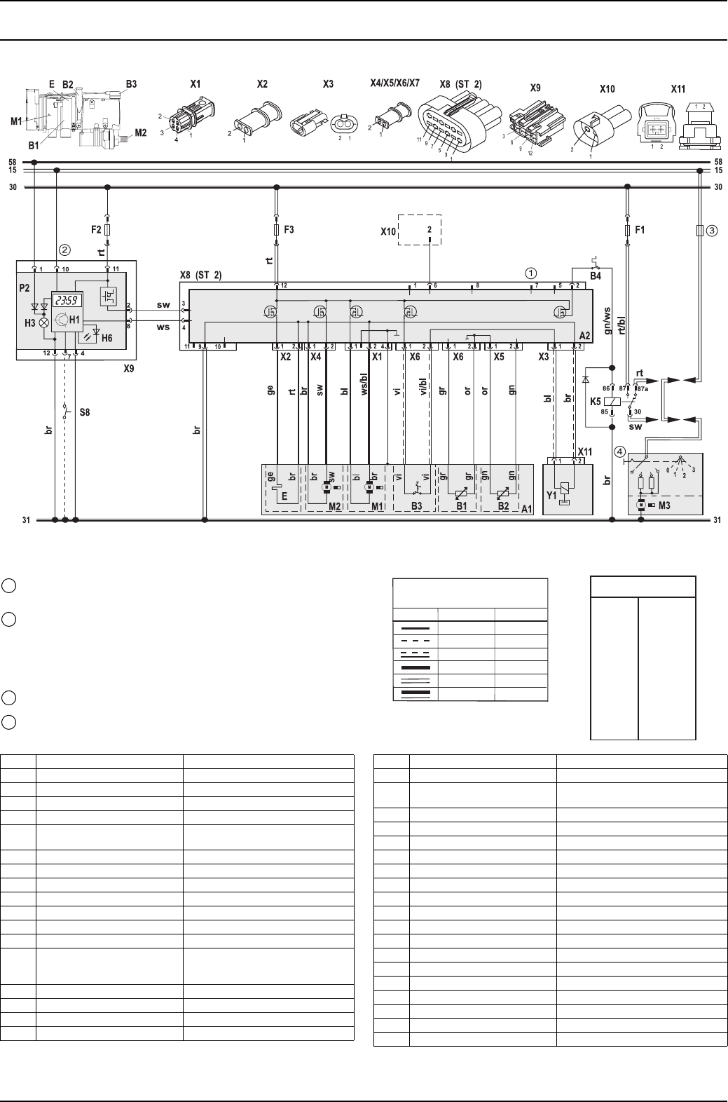
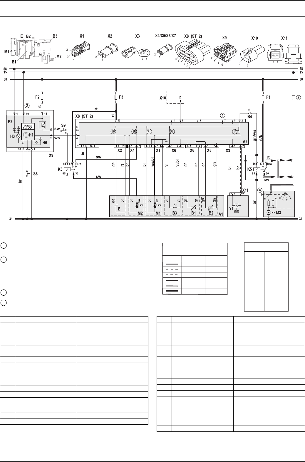
Fig. 701 System circuit for Thermo 90 S, 12 and 24 V, with standard clock
2
8
11
101
12 74
H3
P2
H1
H6
3085
86 87 87a
K5
br
br
br
rt
br gn/ws
rt/bl
ge
sw
rt
ws/bl
vi
bl
vi/bl
gr
gn
or
or
58
15
12
58
15
F2 F3 X6 F1
bl
br
30
30
31
31
sw
rt
sw
rt
ws
A2
11 6
12
2
2
23
1
0
710
32
1
1
1
4
58
11 9
9
4
3
71568
10
212
M2 M3
M1
br
br
bl
239
8657
112
11 10 4
sw
br
X1
X12 (ST 2)
X3
X5
X13
(ST 3)
X11
(ST 1)
Y1
vi
vi
gr
gr
gn
gn
B3
B4
B1 B2 A1
E
M
M
M
X5 X6
ϑϑ
X13 (ST 3)
1
12
2
11
3
10
4
9
5
8
6
7
X1
1
1
2
2
X11 (ST 1) X12 (ST 2)
ge
B1
B3
B2
E
X1
M1
M2
21
X3
S8
6
9
3
12
1
11
3
9
5
7
1
11
3
9
5
7
1
2
1
2
3
4
Temperature coding (temperature at water outlet):
See table on page 302
Digital timer P2:
with positive at connection 10 = Continuous operation with immediate
heating
Connection 10 open = Variable heating duration can be
programmed = (10 min to 120 min);
= Default setting 120 min
Vehicle fuse
Vehicle fan switch
1
2
3
4
Cable cross-sections
< 7.5 m 7.5 - 15 m
0.75 mm2
1.5 mm2
2.5 mm2
4.0 mm2
1.5 mm2
2.5 mm2
4.0 mm
6.0 mm
1.0 mm2
1.0 mm2
1.0 mm2
0.75 mm2
2
2
Cable colours
bl
br
ge
gn
gr
or
rt
sw
vi
ws
Blue
Brown
Yellow
Green
Grey
Orange
Red
Black
Violet
White
Cable colours
bl
br
ge
gn
gr
or
rt
sw
vi
ws
Blue
Brown
Yellow
Green
Grey
Orange
Red
Black
Violet
White
Item Designation Comment
A1 Heater
A2 Control unit
B1 Flame monitor
B2 Temperature sensor
B3 Temperature limiter/
overheating guard circuit
B4 Cabin thermostat
E Glow plug
F1 20 A fuse Blade-type fuse SAE J 1284
F2 5 A fuse Blade-type fuse SAE J 1284
F3 20 A fuse Blade-type fuse SAE J 1284
H1 “Heating” symbol in the display Operating indicator (in item P2)
H3 Symbol light Light (in item P2)
H6 Red LED Light in immediate heat button, ready
indicator, switch-on indicator
(in item P2)
K5 Relay For vehicle fan
M1 Motor Combustion air fan
Item Designation Comment
M2 Motor Circulating pump
M3 Motor Vehicle fan
P2 Standard clock For programmed operation
S8 Momentary-contact switch Immediate heat button remote
control
X1 12-pin plug connector To item A1
X3 12-pin plug connector To item P2
X5 12-pin plug connector To Y1
X6 12-pin plug connector Diagnosis
X11 12-pin plug connector To item A2 (ST 1)
X12 12-pin plug connector To item A2 (ST 2)
X13 12-pin plug connector To item A2 (ST 3)
Y1 Metering pump Fuel pump for heater
Thermo 90 S / Thermo 90 ST 7 Circuit diagrams
703
Fig. 702 System circuit for Thermo 90 S, 12 and 24 V, with standard clock and separate circulating pump control
2
8
11
101
12 74
H3
P2
H1
H6
3030 8585
8686 8787 87a87a
K5K3
br
br
br
rt
rt
br gn/ws
rt/bl
ge
sw
rt
ws/bl
vi
bl
vi/bl
gr
gn
or
or
58
15
12
58
15
F2 F3 X6 F1
bl
br
30
30
31
31
sw
rt
sw
sw
rt
ws
A2
11 6
12
2
2
23
1
0
710
32
1
1
1
4
58
11 9
9
4
3
71568
10
212
M2 M3
M1
br
br
bl
239
8657
112
11 10 4
sw
br
X1
X12 (ST 2)
X3
X5
X13
(ST 3)
X11
(ST 1)
Y1
vi
vi
gr
gr
gn
gn
B3
B4
B1 B2 A1
E
M
M
M
X5 X6
ϑϑ
X13 (ST 3)
1
12
2
11
3
10
4
9
5
8
6
7
X1
1
1
2
2
X11 (ST 1) X12 (ST 2)
ge
B1
B3
B2
E
X1
M1
M2
21
X3
S8
6
9
3
12
1
11
3
9
5
7
1
11
3
9
5
7
1
2
S9
1
2
3
4
Temperature coding (temperature at water outlet):
See table on page 302
Digital timer P2:
with positive at connection 10 = Continuous operation with immediate
heating
Connection 10 open = Variable heating duration can be
programmed = (10 min to 120 min);
= Default setting 120 min
Vehicle fuse
Vehicle fan switch
1
2
3
4
Cable cross-sections
< 7.5 m 7.5 - 15 m
0.75 mm2
1.5 mm2
2.5 mm2
4.0 mm2
1.5 mm2
2.5 mm2
4.0 mm
6.0 mm
1.0 mm2
1.0 mm2
1.0 mm2
0.75 mm2
2
2
Cable colours
bl
br
ge
gn
gr
or
rt
sw
vi
ws
Blue
Brown
Yellow
Green
Grey
Orange
Red
Black
Violet
White
Item Designation Comment
A1 Heater
A2 Control unit
B1 Flame monitor
B2 Temperature sensor
B3 Temperature limiter/
overheating guard circuit
B4 Cabin thermostat
E Glow plug
F1 20 A fuse Blade-type fuse SAE J 1284
F2 5 A fuse Blade-type fuse SAE J 1284
F3 20 A fuse Blade-type fuse SAE J 1284
H1 “Heating” symbol in the display Operating indicator (in item P2)
H3 Symbol light Light (in item P2)
H6 Red LED Light in immediate heat button, ready
indicator, switch-on indicator (in item
P2)
K3 Relay For circulating pump remote control
K5 Relay For vehicle fan
Item Designation Comment
M1 Motor Combustion air fan
M2 Motor Circulating pump
M3 Motor Vehicle fan
P2 Standard clock For programmed operation
S8 Momentary-contact switch Immediate heat button remote
control
S9 Switch Heating/circulating pump remote
control
X1 12-pin plug connector To item A1
X3 12-pin plug connector To item P2
X5 12-pin plug connector To Y1
X6 12-pin plug connector Diagnosis
X11 12-pin plug connector To item A2 (ST 1)
X12 12-pin plug connector To item A2 (ST 2)
X13 12-pin plug connector To item A2 (ST 3)
Y1 Metering pump Fuel pump for heater
7 Circuit diagrams Thermo 90 S / Thermo 90 ST
704
Fig. 703 System circuit for Thermo 90 S-ADR, 24 V, with switch
Temperature coding (temperature at water outlet):
See table on page 302
Vehicle fuse
Vehicle fan switch
1
3
4
A
FE
B
30
85
86 87 87a
H2
S4
K5
br
br
br
rt
br gn/ws
rt/bl
ge
sw
rt
ws/bl
vi
bl
vi/bl
gr
gn
or
or
58
15
12
D+/61
58
15
D+/61
F2 F3 X6 S7 F1
bl
br
30
31
S5
S5
sw
rt
rt
ws
A2
11 6
12
2
2
23
1
0
710
32
1
1
1
4
58
11 9
9
4
3
71568212
M2 M3
M1
br
br
bl
239
8657
112
11 10 4
sw
br
X1
H5 Y2
Y1
vi
gr
gn
B3
B4
B1 B2 A1
E
M
M
M
ϑϑ
ge
B1
B3
B2
E
X1
M1
M2
sw
10
X12 (ST 2)
X5
X13
(ST 3)
X11
(ST 1)
vi
gr
gn
X5 X6
X13 (ST 3)
1
12
2
11
3
10
4
9
5
8
6
7
X1
1
1
2
2
X11 (ST 1) X12 (ST 2)
21
1
11
3
9
5
7
1
11
3
9
5
7
1
2
1
3
4
Cable cross-sections
< 7.5 m 7.5 - 15 m
0.75 mm2
1.5 mm2
2.5 mm2
4.0 mm2
1.5 mm2
2.5 mm2
4.0 mm
6.0 mm
1.0 mm2
1.0 mm2
1.0 mm2
0.75 mm2
2
2
Cable colours
bl
br
ge
gn
gr
or
rt
sw
vi
ws
Blue
Brown
Yellow
Green
Grey
Orange
Red
Black
Violet
White
Item Designation Comment
A1 Heater
A2 Control unit
B1 Flame monitor
B2 Temperature sensor
B3 Temperature limiter/
overheating guard circuit
B4 Cabin thermostat
E Glow plug
F1 20 A fuse Blade-type fuse SAE J 1284
F2 5 A fuse Blade-type fuse SAE J 1284
F3 20 A fuse Blade-type fuse SAE J 1284
H2 Light max. 2 W Operating indicator (in item S4)
H5 Lamp min. 1.2 W Switch-on indicator pumping device
K5 Relay For vehicle fan
M1 Motor Combustion air fan
M2 Motor Circulating pump
M3 Motor Vehicle fan
S4 Switch ON/OFF
Item Designation Comment
S5 1 or 2-pin disconnecting switch Emergency off switch
electrical or pneumatic
S7 Pumping device switch To positive
X1 12-pin plug connector To item A1
X5 12-pin plug connector To Y1
X6 12-pin plug connector Diagnosis
X11 12-pin plug connector To item A2 (ST 1)
X12 12-pin plug connector To item A2 (ST 2)
X13 12-pin plug connector To item A2 (ST 3)
Y1 Metering pump Fuel pump for heater
Y2 Solenoid valve For pumping device
Thermo 90 S / Thermo 90 ST 7 Circuit diagrams
705
Fig. 704 System circuit for Thermo 90 S-ADR, 24 V, with switch without power take-off
Temperature coding (temperature at water outlet):
See table on page 302
Vehicle fuse
Vehicle fan switch
1
3
4
A
FE
B
30
85
86 87 87a
H2
S4
K5
br
br
br
rt
br gn/ws
rt/bl
ge
sw
rt
ws/bl
vi
bl
vi/bl
gr
gn
or
or
58
15
12
D+/61
58
15
D+/61
F2 F3 X6 F1
bl
br
30
31
S5
S5
sw
rt
rt
ws
A2
11 6
12
2
2
23
1
0
710
32
1
1
1
4
58
11 9
9
4
3
71568212
M2 M3
M1
br
br
bl
239
8657
112
11 10 4
sw
br
X1
Y1
vi
gr
gn
B3
B4
B1 B2 A1
E
M
M
M
ϑϑ
ge
B1
B3
B2
E
X1
M1
M2
sw
10
X12 (ST 2)
X5
X13
(ST 3)
X11
(ST 1)
vi
gr
gn
X5 X6
X13 (ST 3)
1
12
2
11
3
10
4
9
5
8
6
7
X1
1
1
2
2
X11 (ST 1) X12 (ST 2)
21
1
11
3
9
5
7
1
11
3
9
5
7
1
2
1
3
4
Cable cross-sections
< 7.5 m 7.5 - 15 m
0.75 mm2
1.5 mm2
2.5 mm2
4.0 mm2
1.5 mm2
2.5 mm2
4.0 mm
6.0 mm
1.0 mm2
1.0 mm2
1.0 mm2
0.75 mm2
2
2
Cable colours
bl
br
ge
gn
gr
or
rt
sw
vi
ws
Blue
Brown
Yellow
Green
Grey
Orange
Red
Black
Violet
White
Item Designation Comment
A1 Heater
A2 Control unit
B1 Flame monitor
B2 Temperature sensor
B3 Temperature limiter/
overheating guard circuit
B4 Cabin thermostat
E Glow plug
F1 20 A fuse Blade-type fuse SAE J 1284
F2 5 A fuse Blade-type fuse SAE J 1284
F3 20 A fuse Blade-type fuse SAE J 1284
H2 Light max. 2 W Operating indicator (in item S4)
K5 Relay For vehicle fan
M1 Motor Combustion air fan
M2 Motor Circulating pump
M3 Motor Vehicle fan
S4 Switch ON/OFF
S5 1 or 2-pin disconnecting switch Emergency off switch
electrical or pneumatic
Item Designation Comment
S7 Pumping device switch To positive
X1 12-pin plug connector To item A1
X5 12-pin plug connector To Y1
X6 12-pin plug connector Diagnosis
X11 12-pin plug connector To item A2 (ST 1)
X12 12-pin plug connector To item A2 (ST 2)
X13 12-pin plug connector To item A2 (ST 3)
Y1 Metering pump Fuel pump for heater
7 Circuit diagrams Thermo 90 S / Thermo 90 ST
706
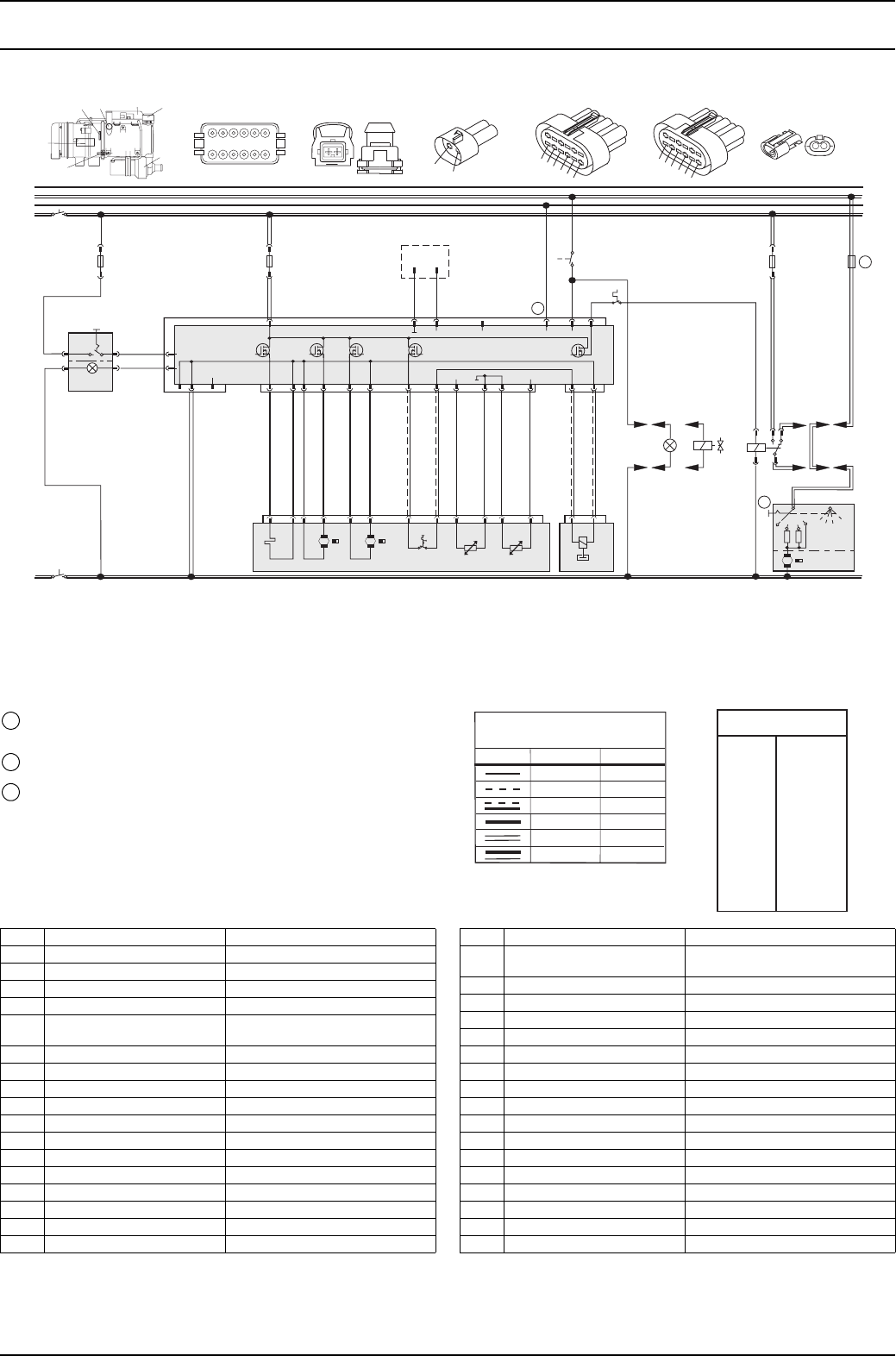
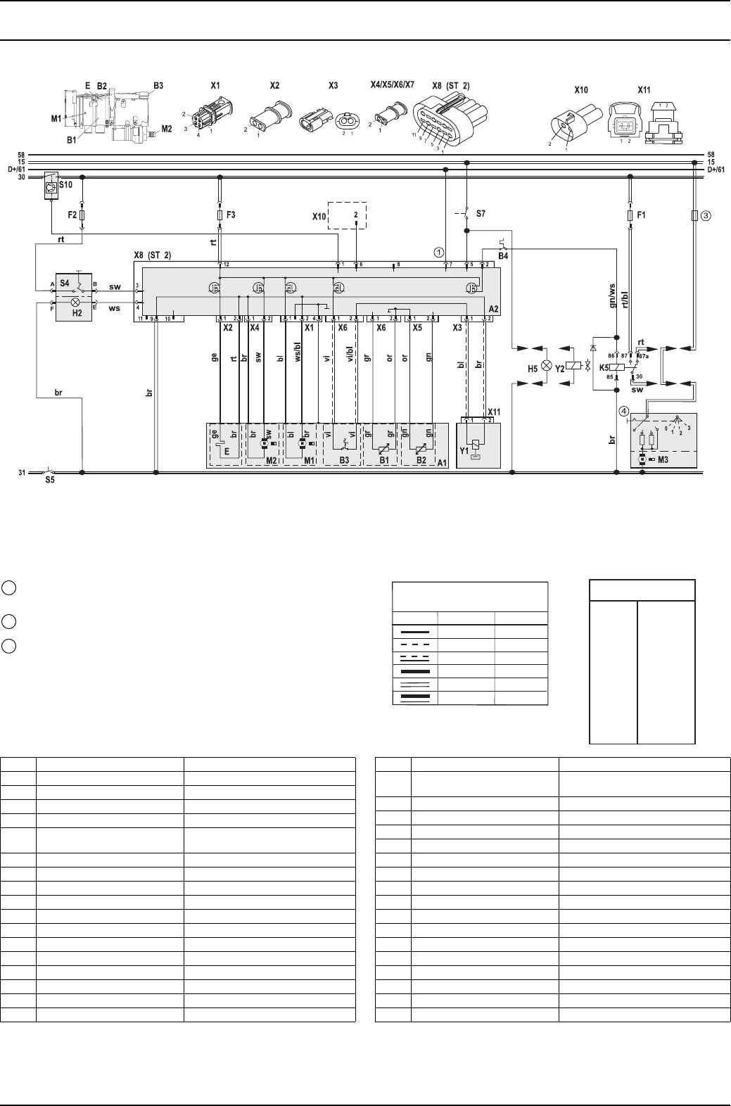
Fig. 705 System circuit for Thermo 90 ST, 12 and 24 V, with standard clock
ϑϑ
Temperature coding (temperature at water outlet):
See table on page 302
Digital timer P2:
with positive at connection 10 = Continuous operation with immediate
heating
Connection 10 open = Variable heating duration can be
programmed = (10 min to 120 min);
= Default setting 120 min
Vehicle fuse
Vehicle fan switch
1
2
3
4
Cable cross-sections
< 7.5 m 7.5 - 15 m
0.75 mm2
1.5 mm2
2.5 mm2
4.0 mm2
1.5 mm2
2.5 mm2
4.0 mm
6.0 mm
1.0 mm2
1.0 mm2
1.0 mm2
0.75 mm2
2
2
Cable colours
bl
br
ge
gn
gr
or
rt
sw
vi
ws
Blue
Brown
Yellow
Green
Grey
Orange
Red
Black
Violet
White
Item Designation Comment
A1 Heater
A2 Control unit
B1 Flame monitor
B2 Temperature sensor
B3 Temperature limiter/
overheating guard circuit
B4 Cabin thermostat
E Glow plug
F1 20 A fuse Blade-type fuse SAE J 1284
F2 5 A fuse Blade-type fuse SAE J 1284
F3 20 A fuse Blade-type fuse SAE J 1284
H1 “Heating” symbol in the display Operating indicator (in item P2)
H3 Symbol light Light (in item P2)
H6 Red LED Light in immediate heat button, ready
indicator, switch-on indicator
(in item P2)
K5 Relay For vehicle fan
M1 Motor Combustion air fan
M2 Motor Circulating pump
M3 Motor Vehicle fan
Item Designation Comment
P2 Standard clock For programmed operation
S8 Momentary-contact switch Immediate heat button remote
control
X1 4-pin plug connector To item A2
X2 2-pin plug connector To item A2
X3 2-pin plug connector To item A2
X4 2-pin plug connector To item A2
X5 12-pin plug connector To item A2
X6 12-pin plug connector Diagnosis
X8 12-pin plug connector To item A2 (ST 2)
X9 12-pin plug connector To item P2
X10 2-pin plug connector W-bus diagnosis
X11 12-pin plug connector To Y1
Y1 Metering pump Fuel pump for heater
Thermo 90 S / Thermo 90 ST 7 Circuit diagrams
707
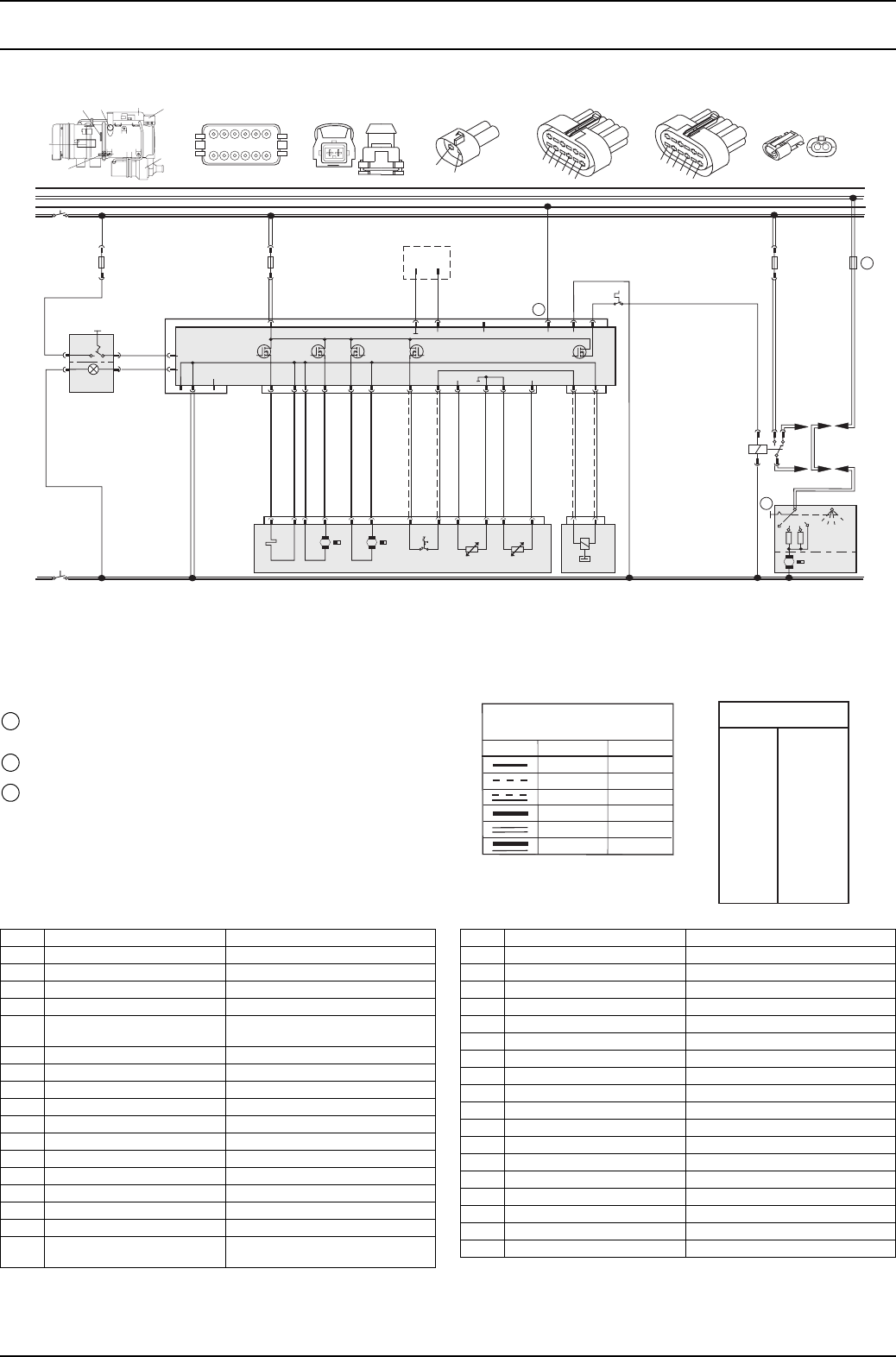
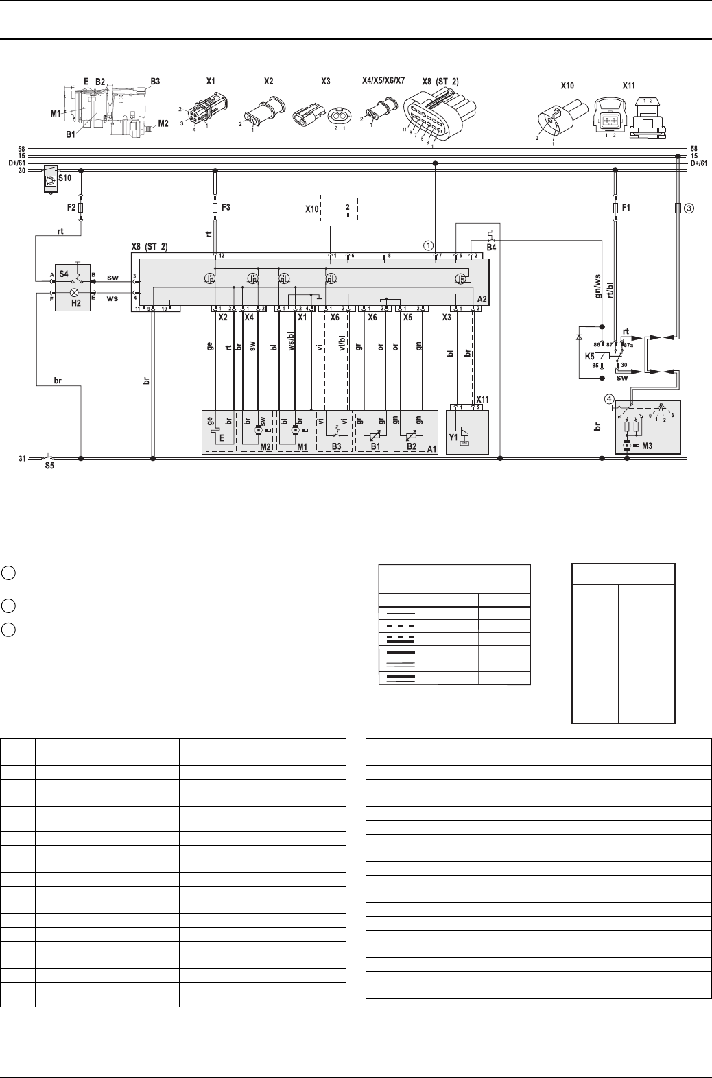
Fig. 706 System circuit for Thermo 90 ST, 12 and 24 V, with standard clock and separate circulating pump control
ϑϑ
Temperature coding (temperature at water outlet):
See table on page 302
Digital timer P2:
with positive at connection 10 = Continuous operation with immediate
heating
Connection 10 open = Variable heating duration can be
programmed = (10 min to 120 min);
= Default setting 120 min
Vehicle fuse
Vehicle fan switch
1
2
3
4
Cable cross-sections
< 7.5 m 7.5 - 15 m
0.75 mm2
1.5 mm2
2.5 mm2
4.0 mm2
1.5 mm2
2.5 mm2
4.0 mm
6.0 mm
1.0 mm2
1.0 mm2
1.0 mm2
0.75 mm2
2
2
Cable colours
bl
br
ge
gn
gr
or
rt
sw
vi
ws
Blue
Brown
Yellow
Green
Grey
Orange
Red
Black
Violet
White
Item Designation Comment
A1 Heater
A2 Control unit
B1 Flame monitor
B2 Temperature sensor
B3 Temperature limiter/
overheating guard circuit
B4 Cabin thermostat
E Glow plug
F1 20 A fuse Blade-type fuse SAE J 1284
F2 5 A fuse Blade-type fuse SAE J 1284
F3 20 A fuse Blade-type fuse SAE J 1284
H1 “Heating” symbol in the display Operating indicator (in item P2)
H3 Symbol light Light (in item P2)
H6 Red LED Light in immediate heat button, ready
indicator, switch-on indicator
(in item P2)
K3 Relay For circulating pump remote control
K5 Relay For vehicle fan
Item Designation Comment
M1 Motor Combustion air fan
M2 Motor Circulating pump
M3 Motor Vehicle fan
P2 Standard clock For programmed operation
S8 Momentary-contact switch Immediate heat button remote
control
S9 Switch Heating/circulating pump remote
control
X1 4-pin plug connector To item A2
X2 2-pin plug connector To item A2
X3 2-pin plug connector To item A2
X4 2-pin plug connector To item A2
X5 12-pin plug connector To item A2
X6 12-pin plug connector Diagnosis
X8 12-pin plug connector To item A2 (ST 2)
X9 12-pin plug connector To item P2
X10 2-pin plug connector W-bus diagnosis
X11 12-pin plug connector To Y1
Y1 Metering pump Fuel pump for heater
7 Circuit diagrams Thermo 90 S / Thermo 90 ST
708
Fig. 707 System circuit for Thermo 90 ST-ADR, 24 V, with switch
ϑϑ
Temperature coding (temperature at water outlet):
See table on page 302
Vehicle fuse
Vehicle fan switch
1
3
4
Cable cross-sections
< 7.5 m 7.5 - 15 m
0.75 mm2
1.5 mm2
2.5 mm2
4.0 mm2
1.5 mm2
2.5 mm2
4.0 mm
6.0 mm
1.0 mm2
1.0 mm2
1.0 mm2
0.75 mm2
2
2
Cable colours
bl
br
ge
gn
gr
or
rt
sw
vi
ws
Blue
Brown
Yellow
Green
Grey
Orange
Red
Black
Violet
White
Item Designation Comment
A1 Heater
A2 Control unit
B1 Flame monitor
B2 Temperature sensor
B3 Temperature limiter/
overheating guard circuit
B4 Cabin thermostat
E Glow plug
F1 20 A fuse Blade-type fuse SAE J 1284
F2 5 A fuse Blade-type fuse SAE J 1284
F3 20 A fuse Blade-type fuse SAE J 1284
H2 Light max. 2 W Operating indicator (in item S4)
H5 Lamp min. 1.2 W Switch-on indicator pumping device
K5 Relay For vehicle fan
M1 Motor Combustion air fan
M2 Motor Circulating pump
M3 Motor Vehicle fan
S4 Switch ON/OFF
Item Designation Comment
S5 1 or 2-pin disconnecting switch Emergency off switch
electrical or pneumatic
S7 Pumping device switch To positive
S10 Switch Battery switch in positive
X1 4-pin plug connector To item A2
X2 2-pin plug connector To item A2
X3 2-pin plug connector To item A2
X4 2-pin plug connector To item A2
X5 12-pin plug connector To item A2
X6 12-pin plug connector Diagnosis
X8 12-pin plug connector To item A2 (ST 2)
X10 2-pin plug connector W-bus diagnosis
X11 12-pin plug connector To Y1
Y1 Metering pump Fuel pump for heater
Y2 Solenoid valve For pumping device
Thermo 90 S / Thermo 90 ST 7 Circuit diagrams
709
Fig. 708 System circuit for Thermo 90 ST-ADR, 24 V, with switch without power take-off
Temperature coding (temperature at water outlet):
See table on page 302
Vehicle fuse
Vehicle fan switch
1
3
4
ϑϑ
Cable cross-sections
< 7.5 m 7.5 - 15 m
0.75 mm2
1.5 mm2
2.5 mm2
4.0 mm2
1.5 mm2
2.5 mm2
4.0 mm
6.0 mm
1.0 mm2
1.0 mm2
1.0 mm2
0.75 mm2
2
2
Cable colours
bl
br
ge
gn
gr
or
rt
sw
vi
ws
Blue
Brown
Yellow
Green
Grey
Orange
Red
Black
Violet
White
Item Designation Comment
A1 Heater
A2 Control unit
B1 Flame monitor
B2 Temperature sensor
B3 Temperature limiter/
overheating guard circuit
B4 Cabin thermostat
E Glow plug
F1 20 A fuse Blade-type fuse SAE J 1284
F2 5 A fuse Blade-type fuse SAE J 1284
F3 20 A fuse Blade-type fuse SAE J 1284
H2 Light max. 2 W Operating indicator (in item S4)
K5 Relay For vehicle fan
M1 Motor Combustion air fan
M2 Motor Circulating pump
M3 Motor Vehicle fan
S4 Switch ON/OFF
S5 1 or 2-pin disconnecting switch Emergency off switch
electrical or pneumatic
Item Designation Comment
S10 Switch Battery switch in positive
X1 4-pin plug connector To item A2
X2 2-pin plug connector To item A2
X3 2-pin plug connector To item A2
X4 2-pin plug connector To item A2
X5 12-pin plug connector To item A2
X6 12-pin plug connector Diagnosis
X8 12-pin plug connector To item A2 (ST 2)
X10 2-pin plug connector W-bus diagnosis
X11 12-pin plug connector To Y1
Y1 Metering pump Fuel pump for heater

7 Circuit diagrams Thermo 90 S / Thermo 90 ST
710
Page for notes

Thermo 90 S / Thermo 90 ST 8 Service work
801
8 Service work
8.1 General
This section describes the service work that can be
carried out on the heater when it is installed.
8.2 Work on the heater
Disconnect the main power cable from the vehicle’s
battery before carrying out any work on the heater. The
main battery power must not be disconnected whilst the
heater is operating or running on as a result of the risk of
the heater overheating and the overheating guard circuit
thus being tripped.
If you wish to carry out extensive repair work on the
heater, it may be a good idea to remove it completely.
After working on the heating circuit, top up with a coolant
mixture of water and antifreeze according to the
manufacturer’s instructions and carefully bleed the
heating circuit.
Refer to the relevant installation instructions and the
installation proposal for the heater for the specific vehicle
for repairs that necessitate the installation position being
changed.
8.3 Work on the vehicle
CAUTION
A temperature of 90 °C must not be exceeded in the
vicinity of the heater in any circumstances (for example
when completing painting work on the vehicle). See
section 4.

8 Service work Thermo 90 S / Thermo 90 ST
802
8.4 Heater trial run
The heater must not be operated in enclosed areas such
as garages and workshops without an emissions
extraction system, even if you use the timer.
8.5 Service work
The following service work is to be carried out after or
before each heating period to maintain the functional
reliability of the heater:
• Clean the exterior of the heater (avoid the ingress of
water).
• Check the electrical connections for contact corrosion
and to ensure that they are secure.
• Check the exhaust and combustion air lines for signs
of damage and to ensure that they are clear.
• Check the fuel line and filter for leaks.
• Check the coolant circuit and circulating pump for
leaks.
• Inspect hoses for cracks.
• Replace the fuel filter if there is one.
Thermo 90 S / Thermo 90 ST 8 Service work
803
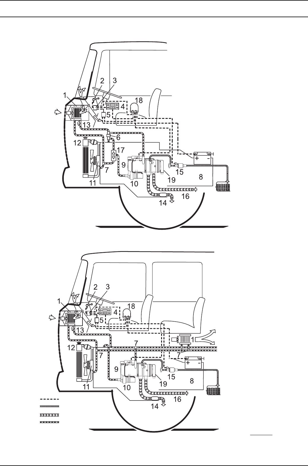
Fig. 801 Specimen installations for heater in a truck
NOTE
The Thermo 90 S and Thermo 90 ST
heater is supplied with the control
unit mounted on the combustion air
fan.
With non-return valve and thermostat
Without non-return valve
1 Heat exchanger
vehicle heating
2 Switch for fan
of the vehicle heating
3 Relay for vehicle fan
4 Digital timer
5 Fuse strip in the car
6 Non-return valve with
leakage hole
7T-piece
8 Vehicle engine
9 Heater
10 Circulating pump
11 Water pump
12 Radiator
13 Regulating valve
14 Exhaust muffler
15 Metering pump
16 Combustion air intake line
17 Thermostat
18 Control unit (optional on the
Thermo 90 S)
19 Control unit (installation
position of Thermo 90 ST
and optionally in
Thermo 90 S)
Wiring harness
Fuel line
Exhaust line
Coolant circuit
8 Service work Thermo 90 S / Thermo 90 ST
804
8.6 Visual inspections and installation
instructions
8.6.1 Connection to the vehicle cooling system
In thermostat circuits, only use thermostats which start to
open at < 65 °C.
The heater should be installed in as low a position as
possible to allow the heater and circulating pump to be
bled automatically.
This is particularly important as the circulating pump is not
self-priming.
The heater is connected to the vehicle cooling system as
shown in Fig. 801. The system must contain at least
6 litres of coolant.
The coolant hoses supplied by Webasto must always be
used. If you do not use these hoses, the hoses that you do
use must comply with DIN 73411. The hoses must be
installed without kinks and (to ensure perfect bleeding)
rising if possible.
Hose connections must be supported by hose clips to
prevent them slipping.
NOTE
The hose clips must be tightened with a torque of 4 Nm.
The cooling system must be bled carefully before using
the heater for the first time or after replacing the coolant.
The heater and lines should be installed in such a way as
to ensure static bleeding.
Perfect ventilation can be identified by the circulating
pump operating almost silently. Poor bleeding may cause
the resetting temperature limiter to trip whilst the heater is
operating.
8.6.2 Connection to the vehicle fuel system
The fuel is taken from the vehicle fuel tank or from a
separate fuel tank.
The values for the maximum pressure at the fuel
extraction point are shown in the table below.
Only for ADR: The statutory regulation of ADR (Accord
européen relatif au transport international des
marchandises dangereuses par route) governing fuel
tanks, part 9 para. 9.2.4.7, must be adhered to.
NOTE
A sign must be affixed to the fuel filler neck warning that
the heater must be switched off before refuelling.
Fig. 802 Fuel supply
Permissible fuel inflow
height H (m)
At max. pressure (bar) in
fuel line
0.00 0.20
1.00 0.11
2.00 0.03
Maximum fuel intake
height S (m)
At max. negative pressure
(bar) in fuel tank
0.00 -0.10
0.50 -0.06
1.00 -0.02
l1+l
2≤ 10.0 m
l1≤ 1.2 m
l2≤ 8.8 m
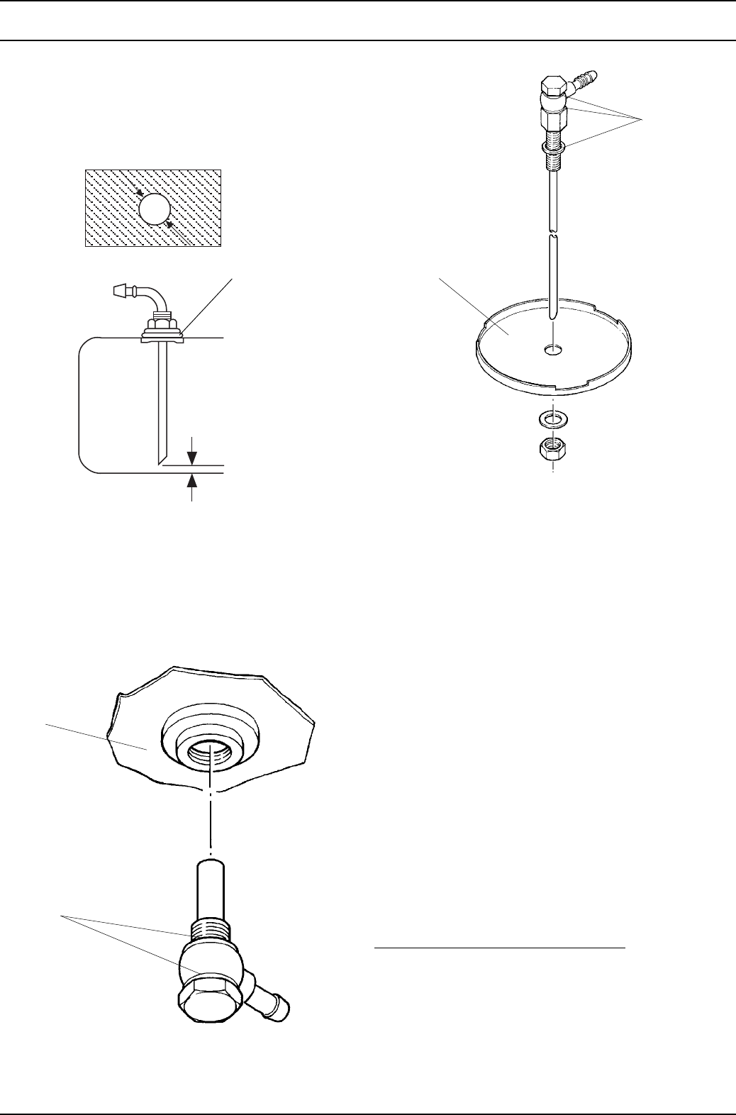
Thermo 90 S / Thermo 90 ST 8 Service work
805
8.6.2.1 Fuel extraction
Vehicles with diesel engines
The fuel must be taken from the vehicle fuel tank or from
a separate tank (Figs. 803, 804 and 805).
Fig. 803 Webasto fuel extractor
NOTE
The fitting must be made from metal!
Fig. 804 Fuel extraction from the plastic tank
(extraction through tank drain screw)
Fig. 805 Fuel extraction from the plastic tank
(extraction through tank fitting)
NOTE
Deburr the cut on the fuel extractor after sawing it off and
remove any metal chips
Vehicles with petrol engines
The heater must be integrated into the return line of fuel
systems in carburettor and injection engines with a return
line.
In carburettor engines without a return line the heater
must be integrated into the fuel system in the supply line
between the fuel tank and the vehicle pump.
NOTE
• A fuel feed line can normally be identified by the fact
that a fuel filter is installed in it.
• If there is an evaporation tank in the vehicle’s fuel
system, the fuel must be extracted upstream of the
evaporation tank.
Fuel may only be taken from the supply or return line
using the special Webasto fuel extractor (Fig. 806). The
fuel extractor must be fitted in such a way that any air or
gas bubbles are automatically discharged towards the
tank (Fig. 806). Air or gas bubbles may be produced in the
vehicle’s fuel line if there are leaks in the carburettor or
vehicle fuel pump or if the ambient temperature is higher
than the evaporation temperature of the fuel.
> 25 mm
25
Hole
pattern
Only use a fuel
extractor with
metal fuel tanks
Sealing ring
Plastic tank
Sealing ring
Tank fitting
Fuel extractor
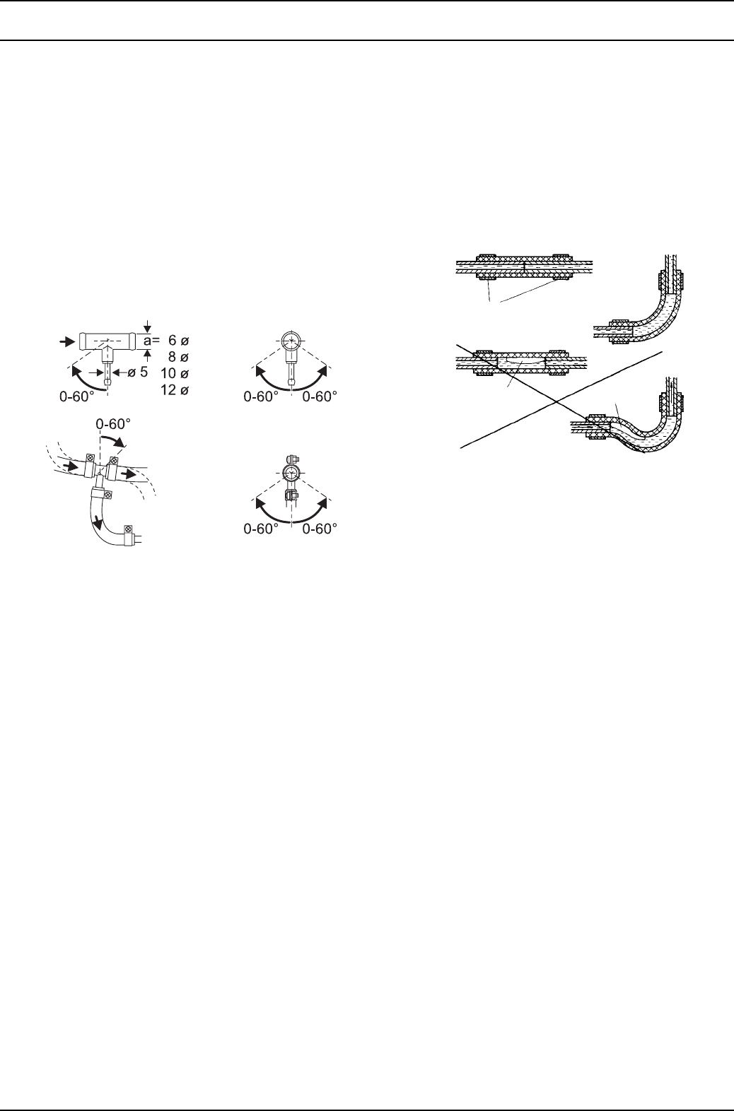
8 Service work Thermo 90 S / Thermo 90 ST
806
The fuel extractor should not be located near the engine,
as gas bubbles may form in the lines on account of heat
radiated from the engine. This may cause problems
during combustion. When installing the heater in a vehicle
with fuel injection system, it is important to establish
whether the fuel pump is located inside or outside the
tank. If the fuel pump is located inside the tank, fuel can
only be extracted from the return line. In this case it must
be ensured that the return line continues almost to the
bottom of the tank and is not sealed by a non-return valve.
If this is not the case the return line may be extended. If
the fuel pump is installed outside the tank, the fuel
connection may be made between the tank and the fuel
pump.
Fig. 806 Webasto fuel extractor
8.6.2.2 Fuel lines
Only steel, copper and plastic lines of plasticised, light and
temperature-stabilized PA 11 or PA 12 (e.g. Mecanyl
RWTL) pursuant to DIN 73378 may be used for the fuel
lines.
NOTE
Cut Mecanyl lines without burr and do not crush them. Do
not cut them with side-cutting pliers.
Since the lines normally cannot be routed with a constant
rising gradient, the internal diameter must not be allowed
to exceed a certain size. Air or gas bubbles will
accumulate in lines with an internal diameter of more than
4 mm and these will cause malfunctions if the lines sag or
are routed downwards. The diameters specified in
Figs. 802 and 806 will ensure that bubbles do not form.
The lines should not be routed downwards from the
metering pump to the heater.
Unsupported fuel lines must be secured to prevent them
sagging. They must be installed in such a way that they
cannot be damaged by flying road chippings and high
temperatures (exhaust line).
The fuel lines must be secure at the connections using
hose clips to prevent their slipping.
Connecting two pipes with a hose
The correct procedure for connecting fuel lines with
hosing is shown in Fig. 807.
NOTE
Ensure that there are no leaks.
Fig. 807 Pipe/hose connection
to engine
from tank
to metering pump
Correct
Wrong
Clip
Bubble Bubble
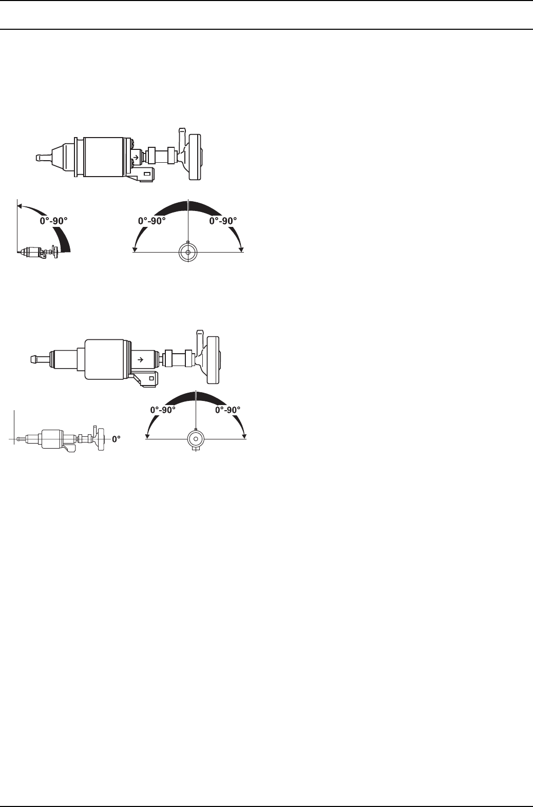
Thermo 90 S / Thermo 90 ST 8 Service work
807
8.6.3 Metering pump with damper
The metering pump is a combined delivery, metering and
shut-off system and is subject to certain installation
criteria (Figs. 802 and 808).
12 volts and 24 volts – petrol and diesel DP2
12 volts and 24 volts – diesel DP 30.2 only
Horizontal installation position
Fig. 808 Metering pump, installation position and
attachment
8.6.3.1 Installation position
Before installing the metering pump, ensure that the
maximum pressure occurring at the pickup point is less
than 0.2 bar
It is advisable to install the metering pump in a cool place.
The maximum ambient temperature must not exceed
+20 °C for petrol and +40 °C for diesel at any time during
operation.
The metering pump and fuel lines must not be installed
within range of the radiated heat from hot vehicle parts.
A heat shield must be used if necessary.
The pump should ideally be installed near the tank.
8.6.3.2 Installation and attachment
The metering pump must be secured with a vibration-
damping mounting. Its installation position is limited as
shown in Fig. 808 in order to ensure effective automatic
bleeding.
8.6.4 Fuel filter
Only a Webasto filter, order no. 487 171, is allowed to be
used if the fuel is expected to be contaminated. Install
vertically if possible, however at least horizontally.
NOTE
Note the installation position and direction of flow.
8.6.5 Combustion air supply
Under no circumstances may the combustion air be taken
from areas occupied by people. The combustion air intake
opening must not point in the direction of travel. It must be
located so that it cannot become clogged with dirt or snow
and cannot suck in splashing water.
The combustion air intake line (internal diameter at least
30 mm) may be 0.5 m to 5 m long with several bends
totalling 360°. Minimum bending radius is 45 mm.
The combustion air inlet must not be routed above the
exhaust outlet.
NOTE
If the combustion air intake line cannot be installed so that
it slopes downwards, a water drain hole (with a diameter
of 4 mm) is to be made at its lowest point.
If the heater is installed in a general installation space
near the vehicle’s fuel tank, the combustion air must be
taken in from the outside and the exhaust fumes
discharged into the atmosphere. The openings must be
splash-proof.
A ventilation opening measuring at least 6 cm2 is required
if the heater is installed in an enclosed box. The size of the
ventilation opening must be increased accordingly if the
temperature in the box exceeds the permitted ambient
temperature of the heater (see Technical data).
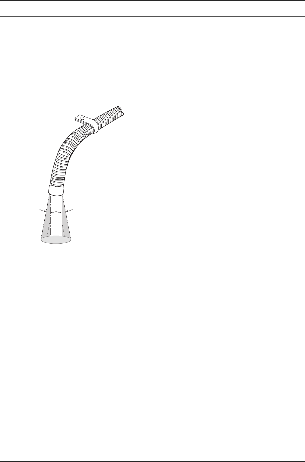
8 Service work Thermo 90 S / Thermo 90 ST
808
8.6.6 Exhaust line
The exhaust line (internal diameter 38 mm) can be
installed with a length of 0.5 m to 5 m and several bends
(360° altogether, minimum bending radius 85 mm). The
exhaust muffler is essential and must be installed near the
heater.
An attachment is required no further than 150 mm from
the end of the exhaust pipe to ensure that the angle of
90° ±10° is achieved.
Fig. 809 Exhaust pipe opening, installation position
The opening of the exhaust pipe must not point towards
the front of the vehicle (see Figure 809).
The exhaust pipe opening must be located so that it
cannot become clogged with snow and mud.
Rigid pipes of unalloyed or alloyed steel with a minimum
wall thickness of 1.0 mm or flexible piping of alloyed steel
only must be used as the exhaust line. The exhaust pipe
is secured to the heater using a clamping collar, for
example. See the statutory regulations for other
requirements.
Only for ADR: The statutory regulation of ADR (Accord
européen relatif au transport international des
marchandises dangereuses par route) governing the
routing of the exhaust line, part 9 para. 9.2.4.7, must be
adhered to.
8.7 Removal and installation
CAUTION
When the heater is installed, only the following
dismantling or removal procedures are permitted
providing the upper cover cap is accessible and can be
removed, and there is sufficient room for removal:
– Changing the circulating pump
– Changing the temperature limiter
– Changing the temperature sensor
– Changing the combustion air fan
– Changing the control unit (Thermo 90 S/
Thermo 90 ST)
8.7.1 Heater, removal and installation
8.7.1.1 Removal
1. Disconnect the battery.
NOTE
Only disconnect plug connectors X12 and X13 on the
control unit in the Thermo 90 S heater with the control
unit flange-mounted on the combustion air fan.
2. Remove the upper cover cap.
3. Disconnect the wiring harness plug from the heater.
4. Disconnect the connection for the combustion air inlet
on the heater.
5. Unfasten the hose clips and pull the coolant hoses off
the heater.
6. Disconnect the connections for the combustion air
inlet and exhaust outlet on the heater.
7. Remove three screws and washers from the heater
holder.
8. Remove the heater.
8.7.1.2 Installation
1. Position the heater in its installation position and
screw in 3 screws with washers to attach it.
2. Connect the coolant hoses and secure with hose
clips. Tighten the hose clips to 5 Nm.
3. Secure the connection for the combustion air inlet on
the heater.
4. Secure the connections for the combustion air inlet
and exhaust outlet on the heater.
NOTE
Only reconnect plug connectors X12 and X13 on the
control unit in the Thermo 90 S heater with the control
unit flange-mounted on the combustion air fan.
5. Connect the wiring harness plug to the heater.
6. Put on the top cover cap and lock it in place.
7. Connect the battery.
8. Bleed the fuel supply system.
9. Bleed the coolant circuit.
10°
10°
Discharge direction
almost vertical 90° ±10°

Thermo 90 S / Thermo 90 ST 8 Service work
809
8.7.2 Changing the circulating pump
NOTE
The process for changing the circulating pump is the
same irrespective of whether the heater is installed or
removed.
Change as described in 9.2.2.
8.7.3 Changing the temperature limiter
NOTE
The process for changing the temperature limiter is the
same irrespective of whether the heater is installed or
removed.
Change as described in 9.2.3.
8.7.4 Changing the temperature sensor
NOTE
The process for changing the temperature sensor is the
same irrespective of whether the heater is installed or
removed.
Change as described in 9.2.4.
8.7.5 Changing the combustion air fan
NOTE
The process for changing the combustion air fan is the
same irrespective of whether the heater is installed or
removed.
Change as described in 9.2.5.
8.8 Start-up
After you have installed the heater, bleed the coolant
circuit and the fuel supply system carefully. Comply with
the instructions given by the vehicle manufacturer when
doing this. During the trial run, check all coolant and fuel
connections for leaks and to ensure that they are secure.
If the heater suffers a fault during operation, the fault must
be located and remedied (see section 5).

Thermo 90 S / Thermo 90 ST 9Repair
901
9 Repair
9.1 General
This section describes the repair work which is permitted
on the heater when it has been removed. Any further
dismantling will invalidate the warranty.
Only use the spare parts from the appropriate spare parts
kits for assembling the heater.
9.1.1 Work on stripped-down components
CAUTION
All seal elements between the dismantled components
must be removed and new ones fitted.
9.1.1.1 Cleaning
• Clean all stripped down components.
9.1.1.2 Visual inspection
• Check all components for damage (cracks,
deformation, wear, etc.) and fit new ones if necessary.
• Inspect the plugs and cables for corrosion, loose
contacts, crimping faults, etc. and repair them if
necessary.
• Check plug contacts for signs of corrosion and to
ensure they are secure. Repair them if necessary.
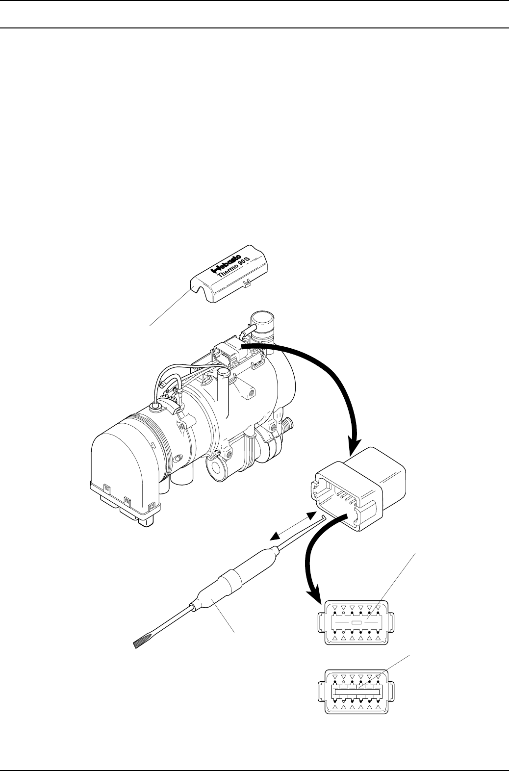
9Repair Thermo 90 S / Thermo 90 ST
902
9.2 Dismantling and assembling
9.2.1 Electrical connections (Thermo 90 S)
9.2.1.1 Disconnecting the electrical connections (plug
connector X1)
NOTE
All electrical connections are grouped together in the plug.
Before removing a component, first disconnect the
corresponding electrical connections.
In the Thermo 90 S heater with flange-mounted
combustion air fan, disconnect plug X1 on the heater and
plug connector X12 on the control unit. Reconnect them
after restoring the electrical connections.
1. Remove the upper cover cap from the heater.
2. Use the removing tool (hook part) to pull the locking
wedge out of the plug.
3. Use the removing tool (screwdriver part) to press the
corresponding locking lug, keep it pressed and pull
the cable out of the plug.
9.2.1.2 Making the electrical connections
1. Push the cable into the corresponding contact hole
until it locks.
2. Use the removing tool (screwdriver part) to insert the
locking wedge in the plug and press in until it locks.
3. Put on the upper cover cap.
Fig. 901 Electrical connections (Thermo 90 S)
Locking wedge
Locking lug
(12 pcs.)
Upper cover cap
Removing tool
Supplier for removing tool
(Order no. DT RT1)
Compagnie Deutsch GmbH
Fraunhoferstr. 11b
D-82152 Martinsried
Tel. +49 (89) 899 1570
Fax +49 (89) 857 4684
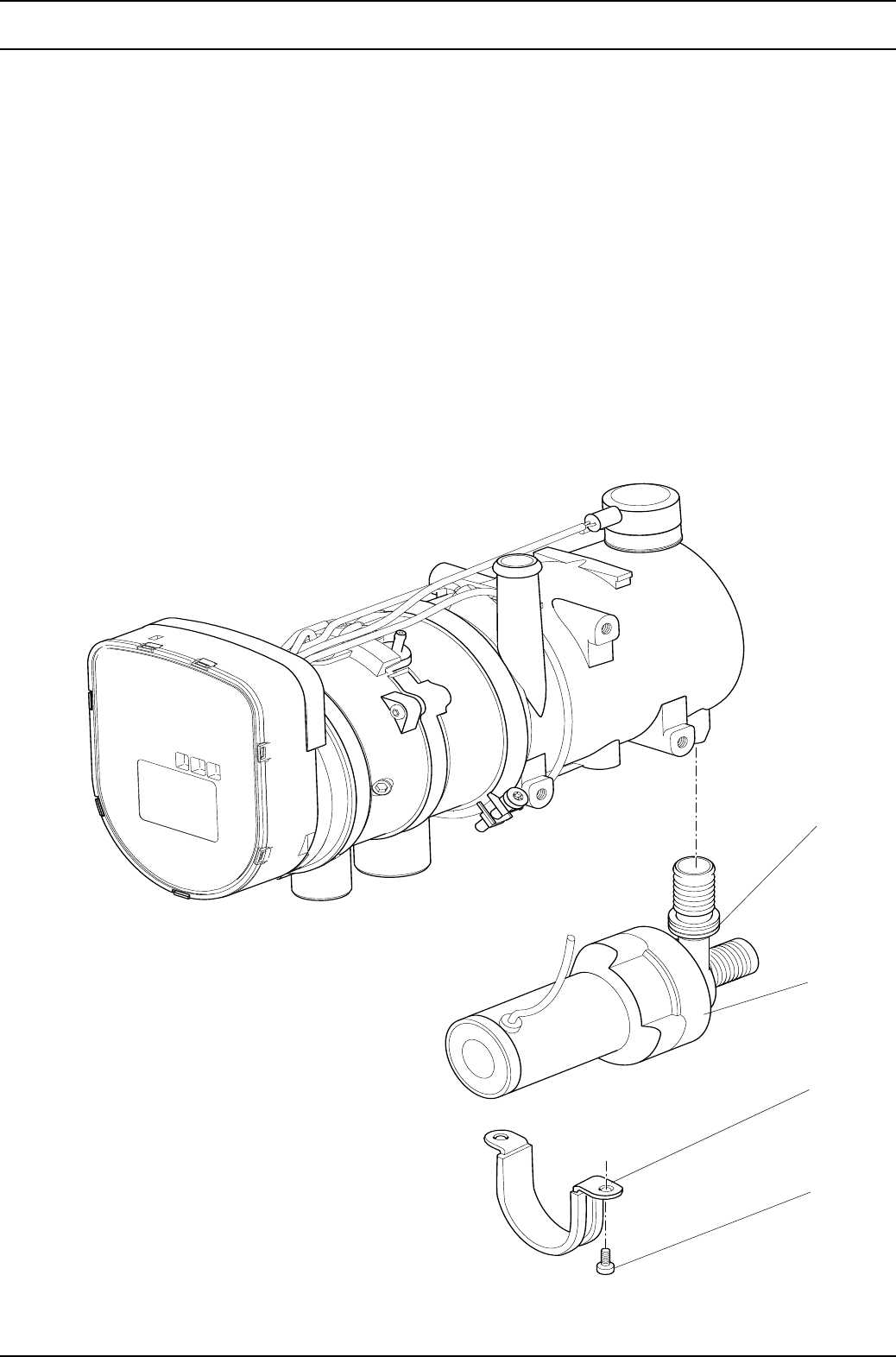
Thermo 90 S / Thermo 90 ST 9Repair
903
9.2.2 Changing the circulating pump
9.2.2.1 Removal
1. Remove the heater (see 8.7.1.1).
2. Disconnect the electrical connections (see 9.2.1.1).
3. Remove the screws (4, Fig. 902).
4. Remove the clip (3) and circulating pump (2).
5. Complete the work on stripped-down components
(see 9.1.1).
9.2.2.2 Installation
1. Apply acid-free grease (Vaseline) to the sealing ring
(1, Fig. 902).
2. Place the circulating pump (2, Fig. 902) in the
assembly position and attach with the clip (3) and
screws (4).
3. Tighten the screws (4) to 3 Nm ±10%.
4. Connect the electrical connections (see 9.2.1.2).
5. Install the heater (see 8.7.1.2).
Fig. 902 Changing the circulating pump
NOTE
A Thermo 90 ST heater is shown. In the Thermo
90 S heater, the control unit can also be
arranged on the combustion air fan without
having any effect on changing the circulating
pump.
1 Sealing ring
2 Circulating
pump
3 Clip
4 Screw (2)
1
2
3
4

9Repair Thermo 90 S / Thermo 90 ST
904
9.2.3 Changing the temperature limiter
9.2.3.1 Removal
NOTE
The temperature limiter only has to be removed if it is
being replaced with a new one.
The function must be checked in the installed condition.
1. Remove the heater (see 8.7.1.1).
2. Disconnect the electrical connections (see 9.2.1.1).
3. Remove the clip (2, Fig. 903) and pull off the
protective cap (1).
4. Use a screwdriver to lever off the retaining spring and
remove the temperature limiter (3).
5. Complete the work on stripped-down components
(see 9.1.1).
NOTE
It is essential to fit a new temperature limiter to replace a
removed one!
9.2.3.2 Installation
CAUTION
Incorrect installation will cause the heat exchanger to
melt.
1. Insert the new temperature limiter (3, Fig. 903) into the
heat exchanger (4) and press in the retaining spring.
NOTE
You must be able to hear and feel the spring clip into
the groove. Only then is the temperature limiter in the
correct installation position.
If you do not hear and feel the spring clip in:
• Clean the contact surface of the temperature limiter
on the heat exchanger
• Clean the groove in the heat exchanger
• Ensure that the detent lugs are present on both sides
of the spring. Fit a new temperature limiter if
necessary.
2. Put on the protective cap (1) and secure it with the
clip (2).
3. Tighten the clip to 1 Nm ±10%.
4. Connect the electrical connections (see 9.2.1.2).
5. Install the heater (see 8.7.1.2).
9.2.4 Changing the temperature sensor
9.2.4.1 Removal
1. Remove the heater (see 8.7.1.1).
2. Disconnect the electrical connections (see 9.2.1.1).
WARNING
Leaking hot coolant can cause burns.
3. Unscrew and remove the temperature sensor
(6, Fig. 903) and remove it together with the round
sealing ring (5).
4. Complete the work on stripped-down components
(see 9.1.1).
9.2.4.2 Installation
1. Apply acid-free grease (Vaseline) to the round sealing
ring (5, Fig. 904).
2. Fit the temperature sensor (6) with the round sealing
ring (5) and screw it into the heat exchanger (4).
Tighten to 1.5 Nm ±10%.
3. Connect the electrical connections (see 9.2.1.2).
4. Install the heater (see 8.7.1.2).
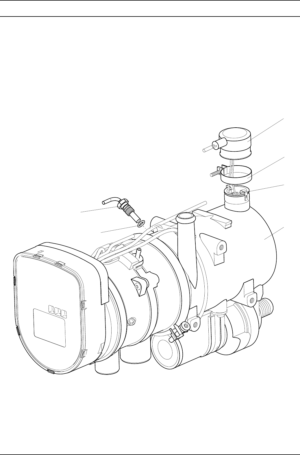
Thermo 90 S / Thermo 90 ST 9Repair
905
Fig. 903 Changing the temperature limiter and temperature sensor
6
5
1
2
3
4
1 Protective cap
2 Clip
3 Temperature limiter
4 Heat exchanger
5 Round sealing ring
6 Temperature sensor
NOTE
A Thermo 90 ST heater is shown. In the
Thermo 90 S heater, the control unit can also be
arranged on the combustion air fan without
having any effect on changing the temperature
sensor.
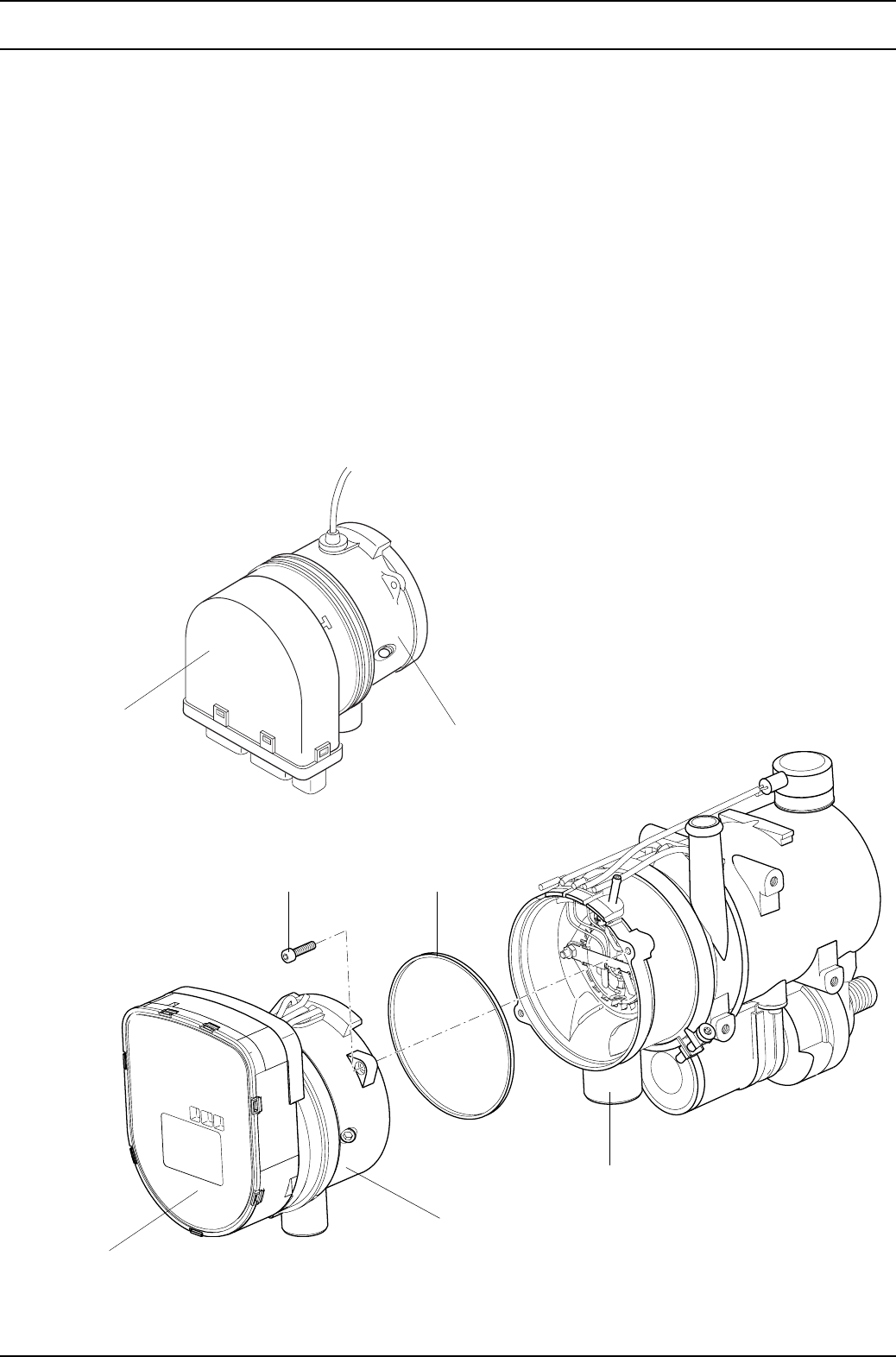
9Repair Thermo 90 S / Thermo 90 ST
906
9.2.5 Changing the combustion air fan
9.2.5.1 Removal
1. Remove the heater (see 8.7.1.1).
2. Disconnect the electrical connections (see 9.2.1.1).
3. Remove the screws (2, Fig. 904).
4. Pull the combustion air fan (1) off the burner head (4)
and remove together with the shaped sealing ring (3).
NOTE
Remove the control unit if necessary from the
Thermo 90 S/Thermo 90 ST heater with flange-
mounted control unit.
5. Complete the work on stripped-down components
(see 9.1.1).
9.2.5.2 Fitting
NOTE
Insert the shaped seal (3, Fig. 904) correctly and grease it
(e.g. with Vaseline). Take care not to squash it.
1. Fit the new shaped sealing ring (3) onto the
combustion air fan (1). Bring the fan into the assembly
position and secure it with screws (2).
2. Tighten the screws (2) to 3 Nm ±10%.
NOTE
Install the control unit if necessary on the Thermo
90 S/Thermo 90 ST heater with flange-mounted
control unit.
3. Connect the electrical connections (see 9.2.1.2).
4. Install the heater (see 8.7.1.2).
Fig. 904 Changing the combustion air fan
Thermo 90 S
Control unit 1
23
4
1
1 Combustion air
fan
2 Screw (2)
3 Shaped sealing
ring
4 Burner head
Control unit
NOTE
A Thermo 90 ST heater is shown.
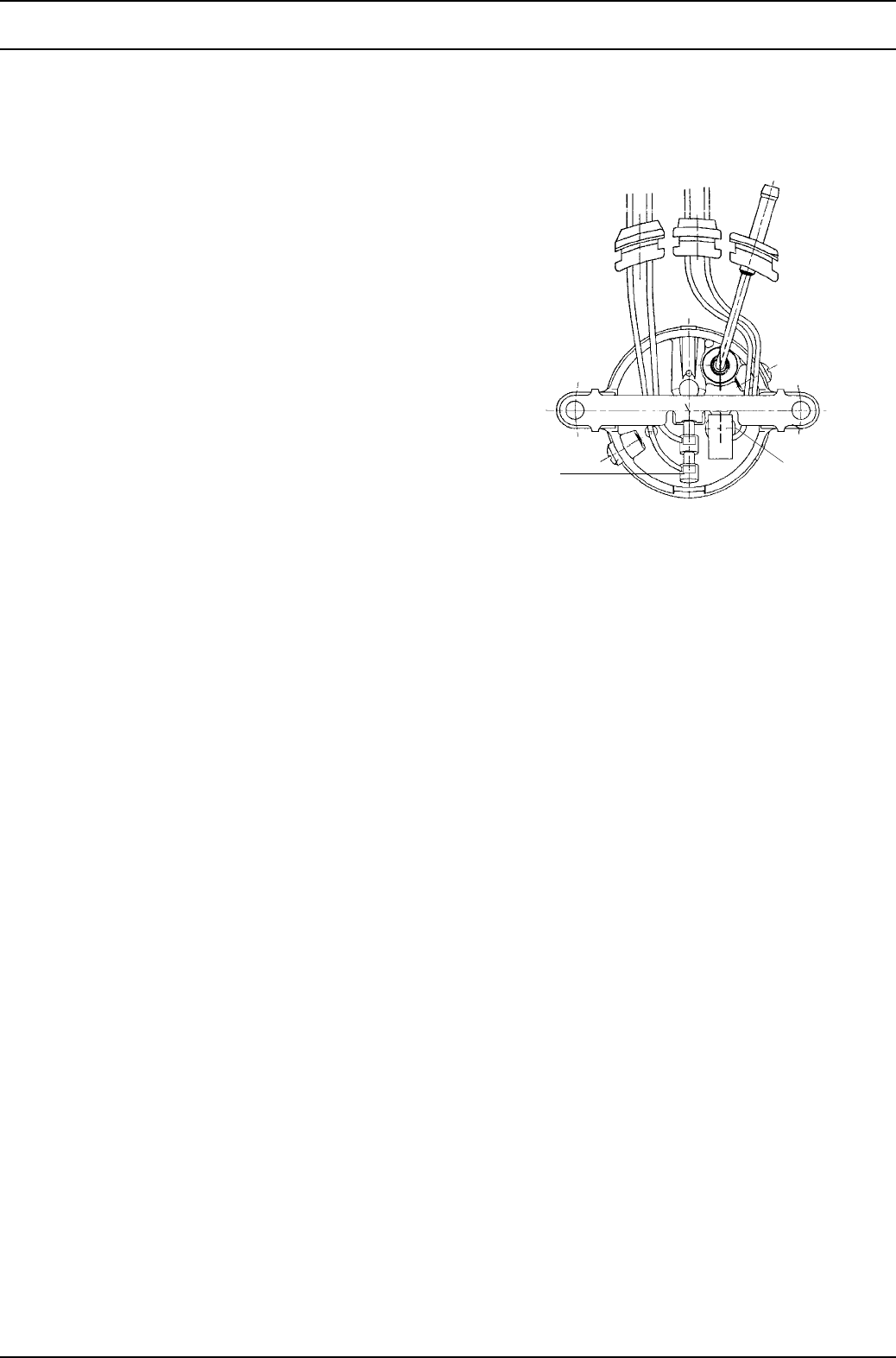
Thermo 90 S / Thermo 90 ST 9Repair
907
9.2.6 Changing the burner, flame monitor and
glow plug
9.2.6.1 Removal
1. Remove the heater (see 8.7.1.1).
2. Remove the combustion air fan (see 9.2.5.1).
3. Remove the screw (5, Fig. 905) and washer (4).
4. Remove the nuts (10) and pull off the bar (8).
5. Pull the grommets (11 and 12) out of the slots in the
housing of the combustion pipe (3).
6. Pull the grommet (13) and burner (1) out of the burner
head and remove with the swirl orifice (2).
7. Pull the flame monitor (7) and glow plug (6) from the
burner (1) and remove.
8. Perform a visual check for assessing the burner
(see 5.3).
9. Complete the work on stripped-down components
(see 9.1.1).
9.2.6.2 Installation
1. Place the swirl orifice (2, Fig. 905) onto the burner (1).
2. Carefully insert the flame monitor (7) and glow plug (6)
into the burner up to the stop and push the grommets
(11 and 12) into the slots in the housing of the burner
pipe (3).
3. Insert the burner (1) and grommet (13) into the burner
head (3).
CAUTION
During the following procedure, make sure that the
cables of the flame monitor (7) and the glow plug (6)
are routed as shown in the figure.
4. Push the insulation (9) onto the bar (8) and bring the
bar into the assembly position.
NOTE
Route the cable of the flame monitor and the glow plug
as shown in the figure!
5. Secure the bar (8) using the nuts (10). Tighten the
nuts to 3 Nm ±10%.
6. Secure the fuel line using the screw (5) and
washer (4). Tighten the screw to 3 Nm ±10%.
7. Fit the combustion air fan (see 9.2.5.2).
8. Connect the electrical connections (see 9.2.1.2).
9. Install the heater (see 8.7.1.2).
Glow plug Flame monitor
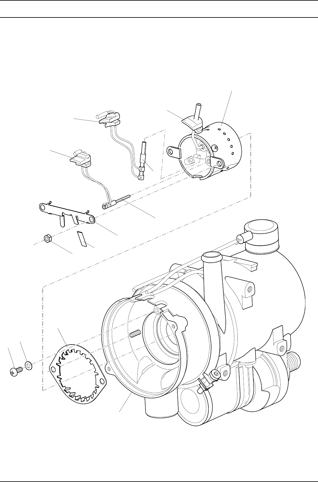
9Repair Thermo 90 S / Thermo 90 ST
908
Fig. 905 Changing the burner, flame monitor and glow plug
1 Burner
2 Swirl orifice
3 Burner head
4 Washer
5Screw
6 Glow plug
7 Flame monitor
8Bar
9 Insulation
10 Nut (2)
11 Grommet
12 Grommet
13 Grommet
NOTE
A Thermo 90 ST heater is shown.
The figure can also be used for the
Thermo 90 S heater.
11
12
6
7
8
9
10
13
1
3
5
4
2
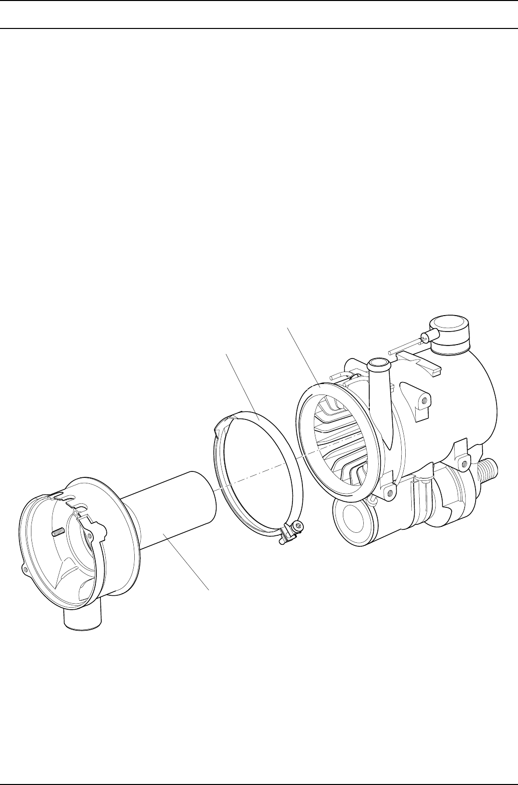
Thermo 90 S / Thermo 90 ST 9Repair
909
9.2.7 Changing the burner head
9.2.7.1 Removal
1. Remove the heater (see 8.7.1.1).
2. Remove the combustion air fan (see 9.2.5.1).
3. Remove the burner, flame monitor and glow plug
(see 9.2.6.1).
4. Remove the mounting screw of the V-clamping collar
(2, Fig. 906) and pull off the clamping collar.
5. Pull out and remove the burner head (1) from the heat
exchanger (3).
6. Complete the work on stripped-down components
(see 9.1.1).
9.2.7.2 Installation
NOTE
The burner head and exhaust outlet port can also be
aligned during installation in the vehicle.
1. Guide the burner head (1, Fig. 906) into the heat
exchanger (3), align it if necessary and secure with
the V-clamping collar (2).
2. If necessary, tighten the mounting screw of the
V-clamping collar to 3 Nm ±10%.
3. Install the burner, flame monitor and glow plug
(see 9.2.6.2).
4. Fit the combustion air fan (see 9.2.5.2).
5. Install the heater (see 8.7.1.2).
Fig. 906 Changing the burner head
1 Burner head
2 V-clamping collar
3 Heat exchanger
1
2
3
NOTE
A Thermo 90 ST heater is shown.
The figure can also be used for the
Thermo 90 S heater.

9Repair Thermo 90 S / Thermo 90 ST
910
9.2.8 Changing the heat exchanger
9.2.8.1 Removal
1. Remove the heater (see 8.7.1.1).
2. Remove the circulating pump (see 9.2.2.1).
3. Remove the temperature limiter (see 9.2.3.1).
4. Remove the temperature sensor (see 9.2.4.1).
5. Remove the combustion air fan (see 9.2.5.1).
6. Remove the burner, flame monitor and glow plug
(see 9.2.6.1).
7. Remove the burner head (see 9.2.7.1).
8. Remove the plug and connector housing.
9. Complete the work on stripped-down components
(see 9.1.1).
9.2.8.2 Installation
1. Clip the connector housing onto the heat exchanger
and insert the plug into the connector housing.
2. Install the burner head (see 9.2.7.2).
3. Install the burner, flame monitor and glow plug
(see 9.2.6.2).
4. Fit the combustion air fan (see 9.2.5.2).
5. Install the temperature sensor (see 9.2.4.2).
6. Install the temperature limiter (see 9.2.3.2).
7. Fit the circulating pump (see 9.2.2.2).
8. Install the heater (see 8.7.1.2).

Thermo 90 S / Thermo 90 ST 10 Packing / Storage / Shipment
1001
10 Packing / Storage and Shipment
10.1 General
If the heater or its components are sent to Webasto
Thermosysteme GmbH for testing or repair, it must be
cleaned and packed in such a way that it is protected
against damage during handling, transport and storage.
CAUTION
Fully drain a complete heater before sending it back.
Make sure that no fuel or coolant can leak out during
packing and/or shipment.
Seal the coolant ports with dummy plugs.
The ambient temperatures listed in section 4 must not be
exceeded during storage.

10 Packing / Storage / Shipment Thermo 90 S / Thermo 90 ST
1002
Page for notes
