Weider 831149222 User Manual PRO 6900 Manuals And Guides 1210310L
User Manual: Weider 831149222 831149222 WEIDER WEIDER PRO 6900 - Manuals and Guides View the owners manual for your WEIDER WEIDER PRO 6900 #831149222. Home:Fitness Equipment Parts:Weider Parts:Weider WEIDER PRO 6900 Manual
Open the PDF directly: View PDF ![]() .
.
Page Count: 32
|
Model No. 831.14922.2
Serial No.
Write the serial number in the space
above for reference.
Serial Number Decal
(under the seat)
•Assembly
• Operation
•Maintenance
•Part List and Drawing
Sears, Roebuck and Co.
Hoffman Estates, IL 60179
WEIGHT SYSTEM EXERCISER
User's Manual
i_w _w_ FREE
(_ HOW-TO "_
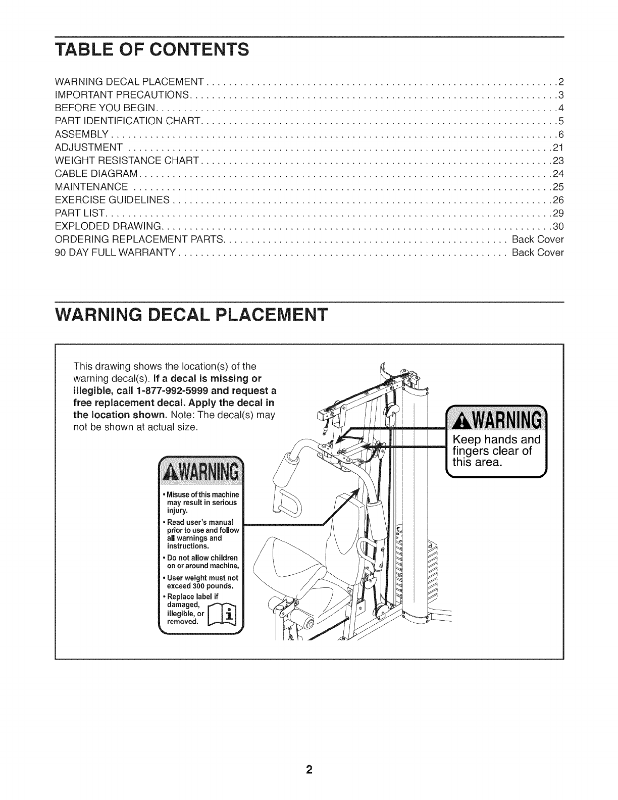
TABLE OF CONTENTS
WARNING DECAL PLACEMENT ............................................................... 2
IMPORTANT PRECAUTIONS .................................................................. 3
BEFORE YOU BEGIN ........................................................................ 4
PART IDENTIFICATION CHART ................................................................ 5
ASSEMBLY ................................................................................ 6
ADJUSTMENT ............................................................................ 21
WEIGHT RESISTANCE CHART ............................................................... 23
CABLE DIAGRAM .......................................................................... 24
MAINTENANCE ........................................................................... 25
EXERCISE GUIDELINES .................................................................... 26
PART LIST ................................................................................ 29
EXPLODED DRAWING ...................................................................... 30
ORDERING REPLACEMENT PARTS ................................................... Back Cover
90 DAY FULL WARRANTY ........................................................... Back Cover
WARNING DECAL PLACEMENT
This drawing shows the location(s) of the
warning decal(s). If a decal is missing or
illegible, call 1-877-992=5999 and request a
free replacement decal. Apply the decal in
the location shown. Note: The decal(s) may
not be shown at actual size.
• Misuseof this machine
may result in serious
injury.
• Read user's manual
prior to use and follow
all warnings and
instructions.
• Do not aflow children
on or around machine,
•User weight must not
exceed 300 pounds,
•Replace label if
damaged, [_
illegible, or
removed,
2
iMPORTANT PRECAUTIONS
3
BEFORE YOU BEGIN
Thank you for selecting the versatile WELDER PRO "R_
6900 weight system. The weight system offers a selec-
tion of weight stations designed to develop every major
muscle group of the body. Whether your goal is to tone
your body, build dramatic muscle size and strength, or
improve your cardiovascular system, the weight system
will help you to achieve the specific results you want.
For your benefit, read this manual carefully before
using the weight system. If you have questions after
reading this manual, please see the front cover of this
manual. To help us assist you, note the product model
number and serial number before contacting us. The
model number and the location of the serial number
decal are shown on the front cover of this manual.
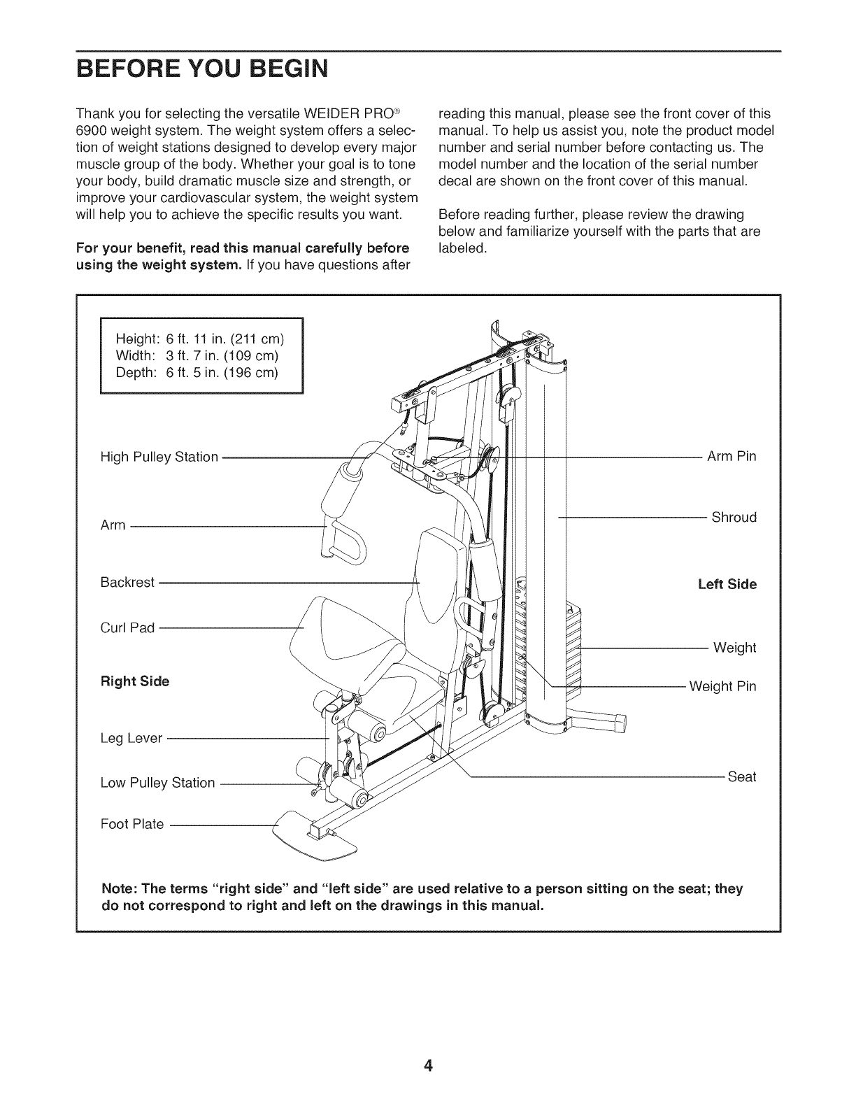
Before reading further, please review the drawing
below and familiarize yourself with the parts that are
labeled.
Height: 6 ft. 11 in. (211 cm)
Width: 3 ft. 7 in. (109 cm)
Depth: 6 ft. 5 in. (196 cm)
High Pulley Station
Arm
Backrest
Curl Pad
Right Side
Leg Lever
Low Pulley Station
Arm Pin
Shroud
Left Side
Weight
Weight Pin
Seat
Foot Plate
Note: The terms "right side" and "left side" are used relative to a person sitting on the seat; they
do not correspond to right and left on the drawings in this manual.
4

PART iDENTiFiCATiON CHART
Refer to the drawings below to identify small parts used in assembly. The number in parentheses by each drawing
is the key number of the part, from the PART LIST near the end of this manual, iMPORTANT: If you cannot find
apart in the hardware kit, check to see if it has been preassembled. If a part is missing, please call 1=877=
992=5999. To avoid damaging parts, do not use power tools for assembly.
13mm Spacer
(52)
11mm Spacer
(86)
M4 Washer
(33) H
M6 Washer (82)
M8 Washer (59)
M10 Washer (57)
Large Washer (85)
M10 x 25mm Screw(74)
MIO x 25mm
Button Screw (77)
M8 x 22mm
Shoulder Bolt (65)
M4 x 20mm
Self-tapping Screw (69)
M12 Nut (84)
M10 Locknut (56)
M8 Locknut (58) (
L
M6 x 32mm Screw (64)
M6 x 38mm Screw (95)
I M10 x 46mm Bolt (81)
I M10 x 51 mm Bolt (66)
M8 x 63mm Carriage Bolt (87)
MIO x 63mm Bolt (75) _
M8 x 65mm Bolt (68)
M6 x 16mm
Screw (62)
M4.2 x 16mm
Self-tapping Screw (49)
M4 x 12ram
Screw (78)
M10 x 67mm Bolt (71)
M10 x 77mm Bolt (79)
M10 x 86mm Carriage Bolt (67)
M10 x 64mm Bolt Set (76)
M10 x 130mm Bolt (72)
5
ASSEMBLY
Assembly requires two persons.
Because of its weight and size, assemble the
weight system in the location where it will be
used. Make sure that there is enough clearance
to walk around the weight system.
Place all parts in a cleared area and remove the
packing materials. Do not dispose of the packing
materials until assembly is completed.
For help identifying small parts, use the PART
IDENTIFICATION CHART on page 5.
• The following tool(s) (not included) may be
required for assembly:
two adjustable wrenches
one rubber mallet c (_
one standard screwdriver (_:3====_
one Phillips screwdriver
Assembly may be easier if you have a set of
wrenches. To avoid damaging parts, do not use
power tools.
The Four Stages of the Assembly Process
Frame Assembly--You will begin by assembling
the base and the uprights that form the skeleton of
the weight system.
Arm Assembly--During this stage you will assem-
ble the arms and the leg lever.
Cable Assembly--During this stage you will attach
the cables and pulleys that connect the arms to the
weights.
Seat Assembly--During the final stage you will
assemble the seat and the backrest.
6
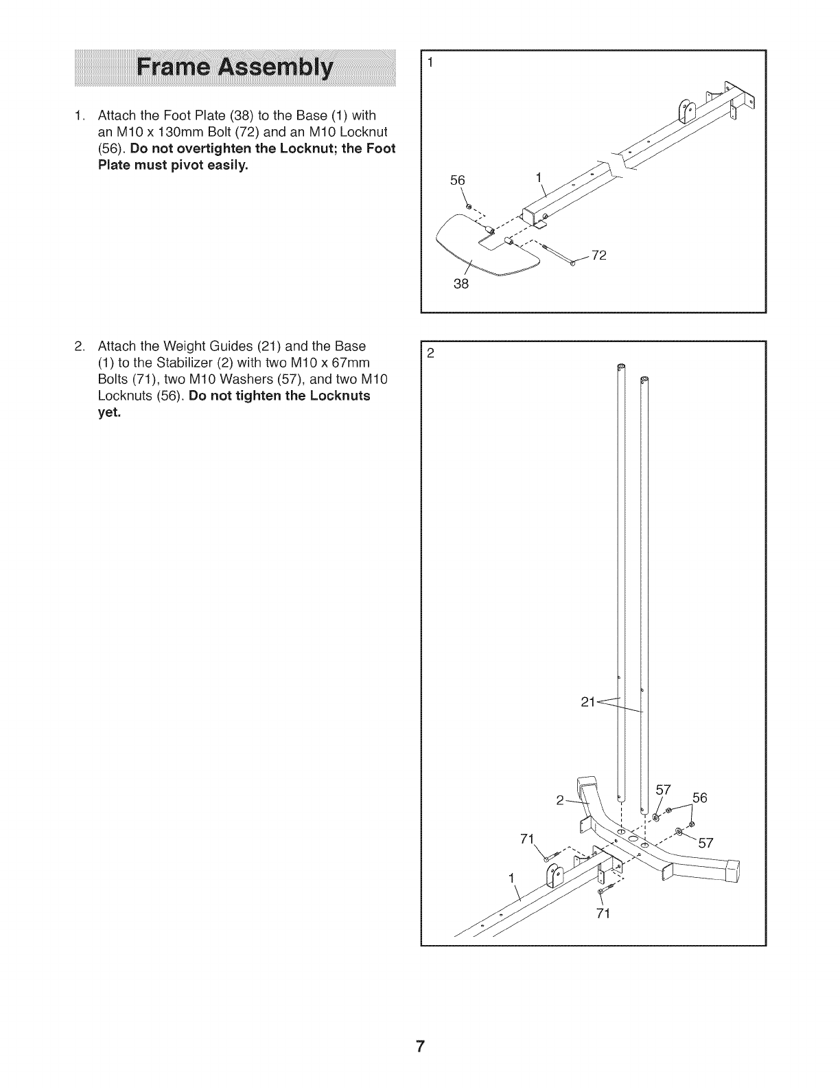
,Attach the Foot Plate (38) to the Base (1) with
an M10 x 130mm Bolt (72) and an M10 Locknut
(56). Do not overtighten the Locknut; the Foot
Plate must pivot easily. 56
38
,Attach the Weight Guides (21) and the Base
(1) to the Stabilizer (2) with two M10 x 67mm
Bolts (71), two M10 Washers (57), and two M10
Locknuts (56). Do not tighten the Locknuts
yet.
71
71
7
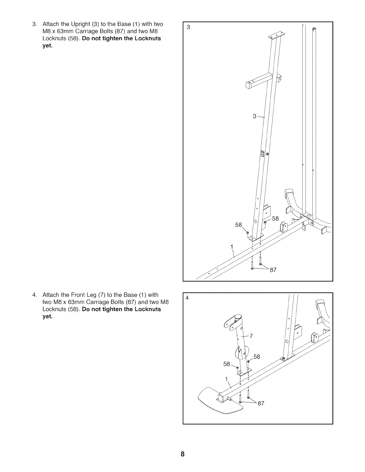
,Attach the Upright (3) to the Base (1) with two
M8 x 63mm Carriage Bolts (87) and two M8
Locknuts (58). Do not tighten the Locknuts
yet.
58 58
87
,Attach the Front Leg (7) to the Base (1) with
two M8 x 63mm Carriage Bolts (87) and two M8
Locknuts (58). Do not tighten the Locknuts
yet.
4
58
87
8
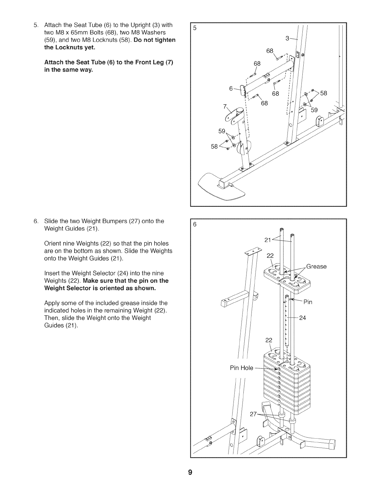
5. 5
Attach the Seat Tube (6) to the Upright (3) with
two M8 x 65mm Bolts (68), two M8 Washers
(59), and two M8 Locknuts (58). Do not tighten
the Locknuts yet.
Attach the Seat Tube (6) to the Front Leg (7)
in the same way.
59
68
68
68
,Slide the two Weight Bumpers (27) onto the
Weight Guides (21).
Orient nine Weights (22) so that the pin holes
are on the bottom as shown. Slide the Weights
onto the Weight Guides (21).
Insert the Weight Selector (24) into the nine
Weights (22). Make sure that the pin on the
Weight Selector is oriented as shown.
Apply some of the included grease inside the
indicated holes in the remaining Weight (22).
Then, slide the Weight onto the Weight
Guides (21).
Pin Hole
Grease
24
22
9
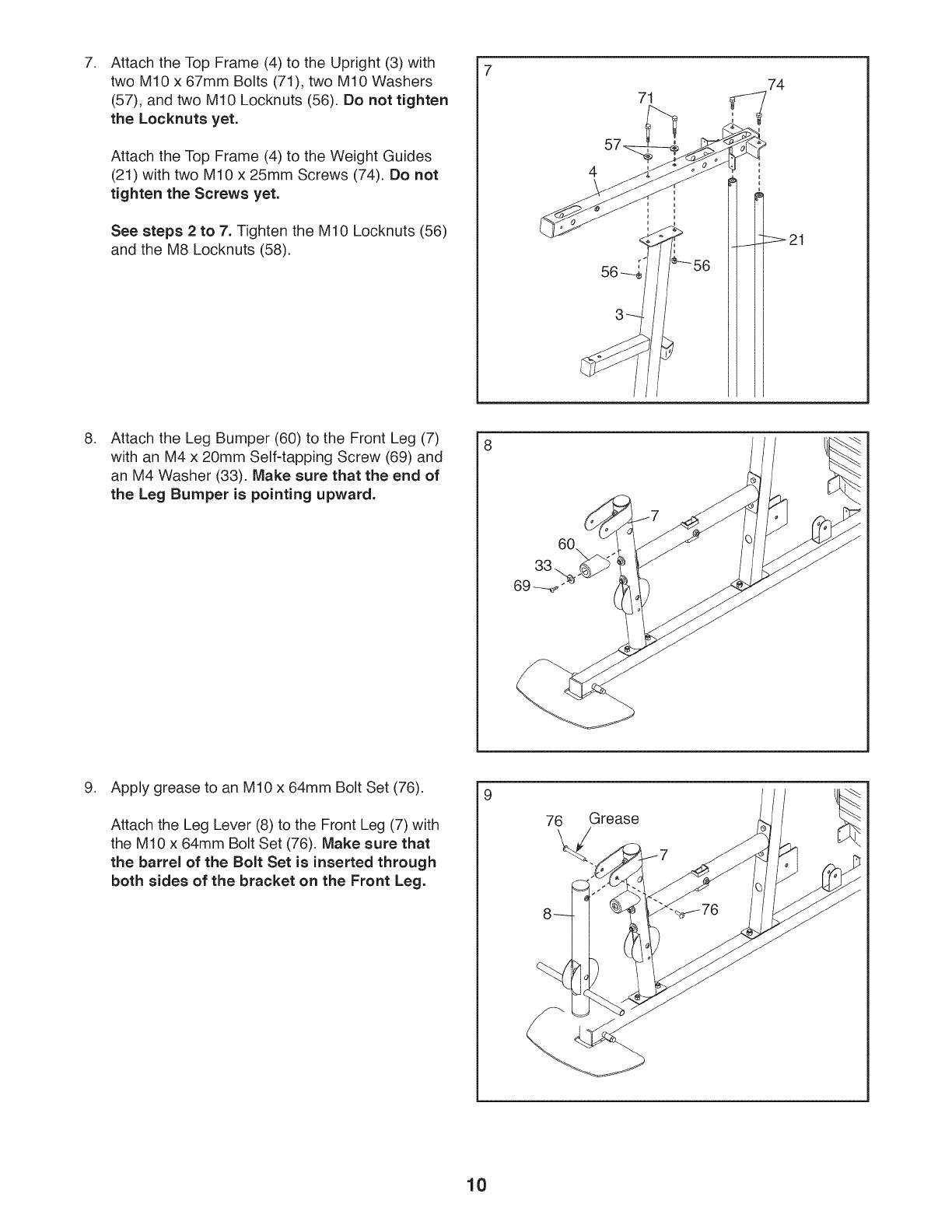
,Attach the Top Frame (4) to the Upright (3) with
two M10 x 67mm Bolts (71), two M10 Washers
(57), and two M10 Locknuts (56). Do not tighten
the Locknuts yet.
Attach the Top Frame (4) to the Weight Guides
(21) with two M10 x 25mm Screws (74). Do not
tighten the Screws yet.
See steps 2 to 7. Tighten the M10 Locknuts (56)
and the M8 Locknuts (58).
71 74
,Attach the Leg Bumper (60) to the Front Leg (7)
with an M4 x 20mm Self-tapping Screw (69) and
an M4 Washer (33). Make sure that the end of
the Leg Bumper is pointing upward.
8
9. Apply grease to an M10 x 64mm Bolt Set (76).
Attach the Leg Lever (8) to the Front Leg (7) with
the M10 x 64mm Bolt Set (76). Make sure that
the barrel of the Bolt Set is inserted through
both sides of the bracket on the Front Leg.
9
76 Grease
10

10. Apply grease to an M10 x 77mm Bolt (79).
Attach the Pivot Frame (5) to the Top Frame
(4) with the M10 x 77mm Bolt (79) and an M10
Locknut (56). Do not overtighten the Locknut;
the Pivot Frame must pivot easily.
10
'," Grease
11. Attach the two Arm Pins (40) to the Pivot
Frame (5) with two M4 x 20mm Self-tapping
Screws (69).
See the inset drawing. Insert the Arm Pins (40)
into the indicated holes in the Upright (3).
11
69
/
/
12. Apply grease to an M10 x 51mm Bolt (66).
Attach a Cable Pivot (39)to the Left Arm (10)
with the M10 x 51mm Bolt (66) and an M10
Locknut (56). Do not overtighten the Locknut;
the Cable Pivot must pivot easily.
Wet the inside of a Large Foam Pad (42) with
soapy water. Slide the Large Foam Pad onto the
Left Arm (10).
Attach a Handle (11) to the Left Arm (10) with
two M10 x 25mm Button Screws (77) and two
M10 Washers (57).
Assemble the Right Arm (9) in the same way.
12
66
'_ Grease
-_39
11
/ 57
77
11
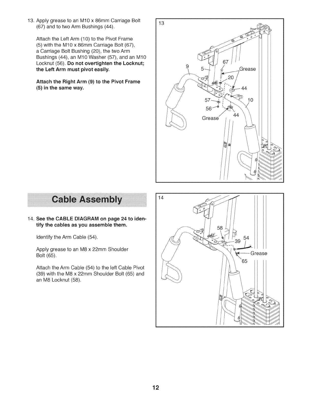
13. Apply grease to an M10 x 86mm Carriage Bolt
(67) and to two Arm Bushings (44).
Attach the Left Arm (10) to the Pivot Frame
(5) with the M10 x 86mm Carriage Bolt (67),
a Carriage Bolt Bushing (20), the two Arm
Bushings (44), an M10 Washer (57), and an M10
Locknut (56). Do not overtighten the Locknut;
the Left Arm must pivot easily.
Attach the Right Arm (9) to the Pivot Frame
(5) in the same way.
13
Grease
14. See the CABLE DIAGRAM on page 24 to iden-
tify the cables as you assemble them.
Identify the Arm Cable (54).
Apply grease to an M8 x 22mm Shoulder
Bolt (65).
Attach the Arm Cable (54) to the left Cable Pivot
(39) with the M8 x 22mm Shoulder Bolt (65) and
an M8 Locknut (58).
14
12
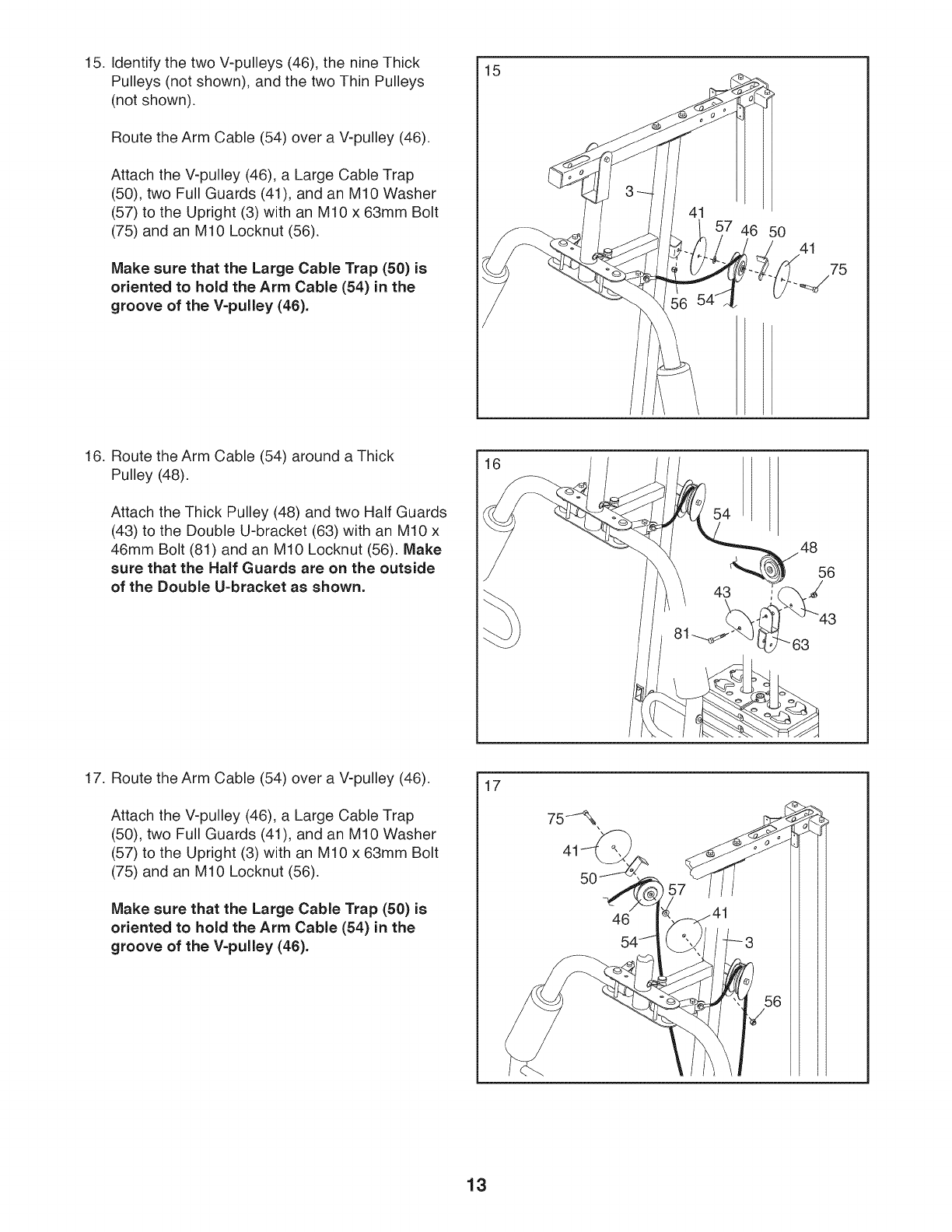
15. Identify the two V-pulleys (46), the nine Thick
Pulleys (not shown), and the two Thin Pulleys
(not shown).
Route the Arm Cable (54) over a V-pulley (46).
Attach the V-pulley (46), a Large Cable Trap
(50), two Full Guards (41), and an M10 Washer
(57) to the Upright (3) with an M10 x 63mm Bolt
(75) and an M10 Locknut (56).
Make sure that the Large Cable Trap (50) is
oriented to hold the Arm Cable (54) in the
groove of the V=pulley (46).
15
7 46 50 41
75
16. Route the Arm Cable (54) around a Thick
Pulley (48).
Attach the Thick Pulley (48) and two Half Guards
(43) to the Double U-bracket (63) with an M10 x
46mm Bolt (81) and an M10 Locknut (56). Make
sure that the Half Guards are on the outside
of the Double U=bracket as shown.
16
54
48
56
J
17. Route the Arm Cable (54) over a V-pulley (46).
Attach the V-pulley (46), a Large Cable Trap
(50), two Full Guards (41), and an M10 Washer
(57) to the Upright (3) with an M10 x 63mm Bolt
(75) and an M10 Locknut (56).
Make sure that the Large Cable Trap (50) is
oriented to hold the Arm Cable (54) in the
groove of the V=pulley (46).
17
46
i7
13
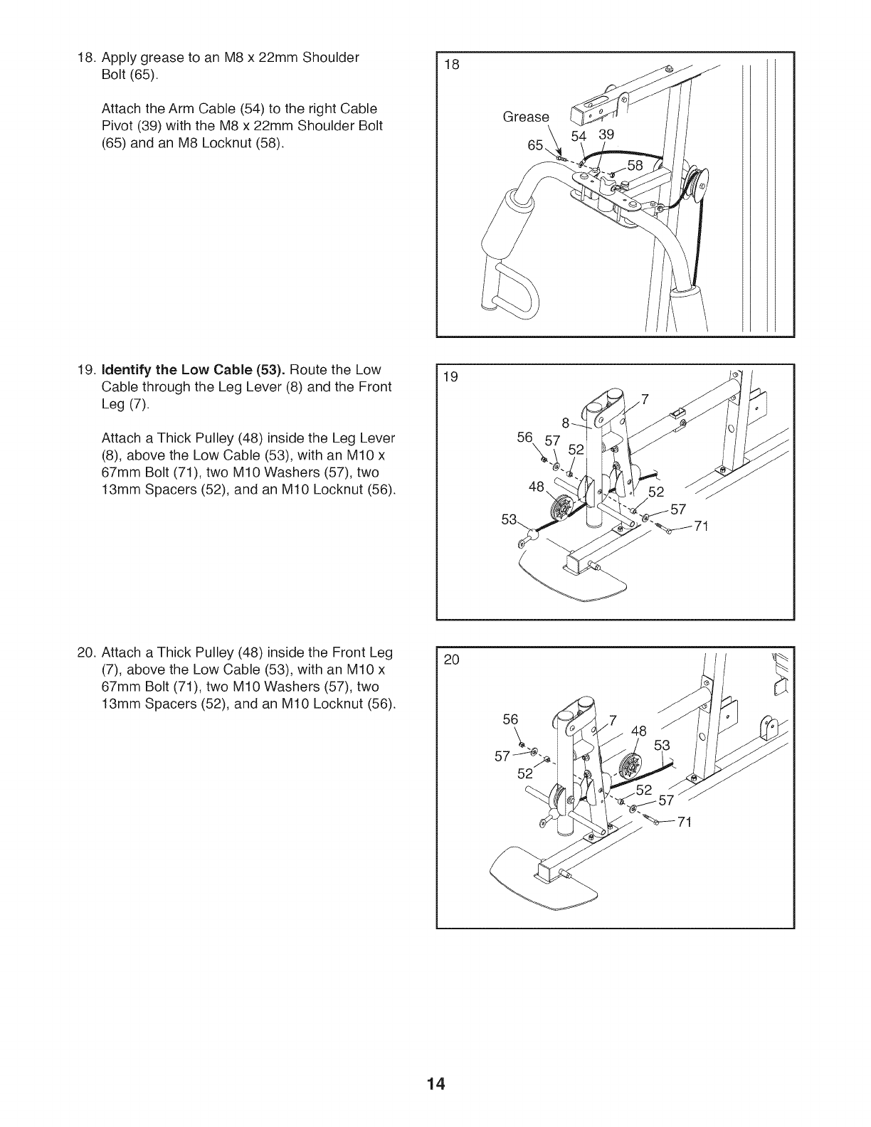
18. Apply grease to an M8 x 22mm Shoulder
Bolt (65).
Attach the Arm Cable (54) to the right Cable
Pivot (39) with the M8 x 22mm Shoulder Bolt
(65) and an M8 Locknut (58).
18
Grease
19. Identify the Low Cable (53). Route the Low
Cable through the Leg Lever (8) and the Front
Leg (7).
Attach a Thick Pulley (48) inside the Leg Lever
(8), above the Low Cable (53), with an M10 x
67mm Bolt (71), two M10 Washers (57), two
13mm Spacers (52), and an M10 Locknut (56).
19
56\
71
20. Attach a Thick Pulley (48) inside the Front Leg
(7), above the Low Cable (53), with an M10 x
67mm Bolt (71), two M10 Washers (57), two
13mm Spacers (52), and an M10 Locknut (56).
20
56
52
48
14
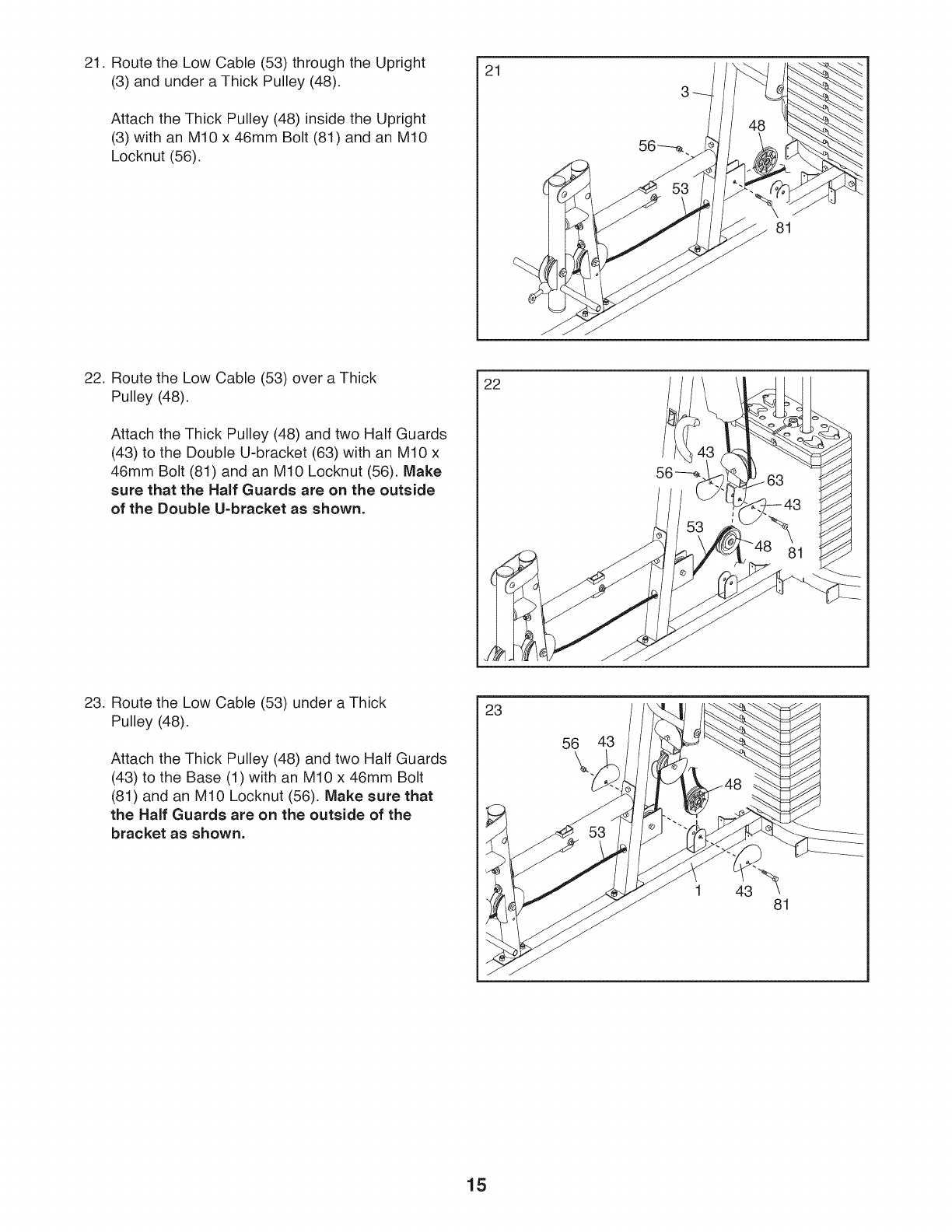
21. Route the Low Cable (53) through the Upright
(3) and under a Thick Pulley (48).
Attach the Thick Pulley (48) inside the Upright
(3) with an M10 x 46mm Bolt (81) and an M10
Locknut (56).
21
J
81
22. Route the Low Cable (53) over a Thick
Pulley (48).
Attach the Thick Pulley (48) and two Half Guards
(43) to the Double U-bracket (63) with an M10 x
46mm Bolt (81) and an M10 Locknut (56). Make
sure that the Half Guards are on the outside
of the Double U=bracket as shown.
22
23. Route the Low Cable (53) under a Thick
Pulley (48).
Attach the Thick Pulley (48) and two Half Guards
(43) to the Base (1)with an M10 x 46mm Bolt
(81) and an M10 Locknut (56). Make sure that
the Half Guards are on the outside of the
bracket as shown.
23
56 43
15
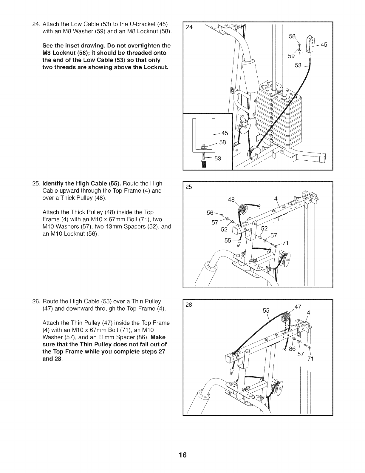
24. Attach the Low Cable (53) to the U-bracket (45)
with an M8 Washer (59) and an M8 Locknut (58).
See the inset drawing. Do not overtighten the
M8 Locknut (58); it should be threaded onto
the end of the Low Cable (53) so that only
two threads are showing above the Locknut.
24
45
58
25. identify the High Cable (55). Route the High
Cable upward through the Top Frame (4) and
over a Thick Pulley (48).
Attach the Thick Pulley (48) inside the Top
Frame (4) with an M10 x 67mm Bolt (71), two
M10 Washers (57), two 13mm Spacers (52), and
an M10 Locknut (56).
25
48
26. Route the High Cable (55) over a Thin Pulley
(47) and downward through the Top Frame (4).
Attach the Thin Pulley (47) inside the Top Frame
(4) with an M10 x 67mm Bolt (71), an M10
Washer (57), and an 11mm Spacer (86). Make
sure that the Thin Pulley does not fall out of
the Top Frame while you complete steps 27
and 28.
26 55 47
57
4
71
16
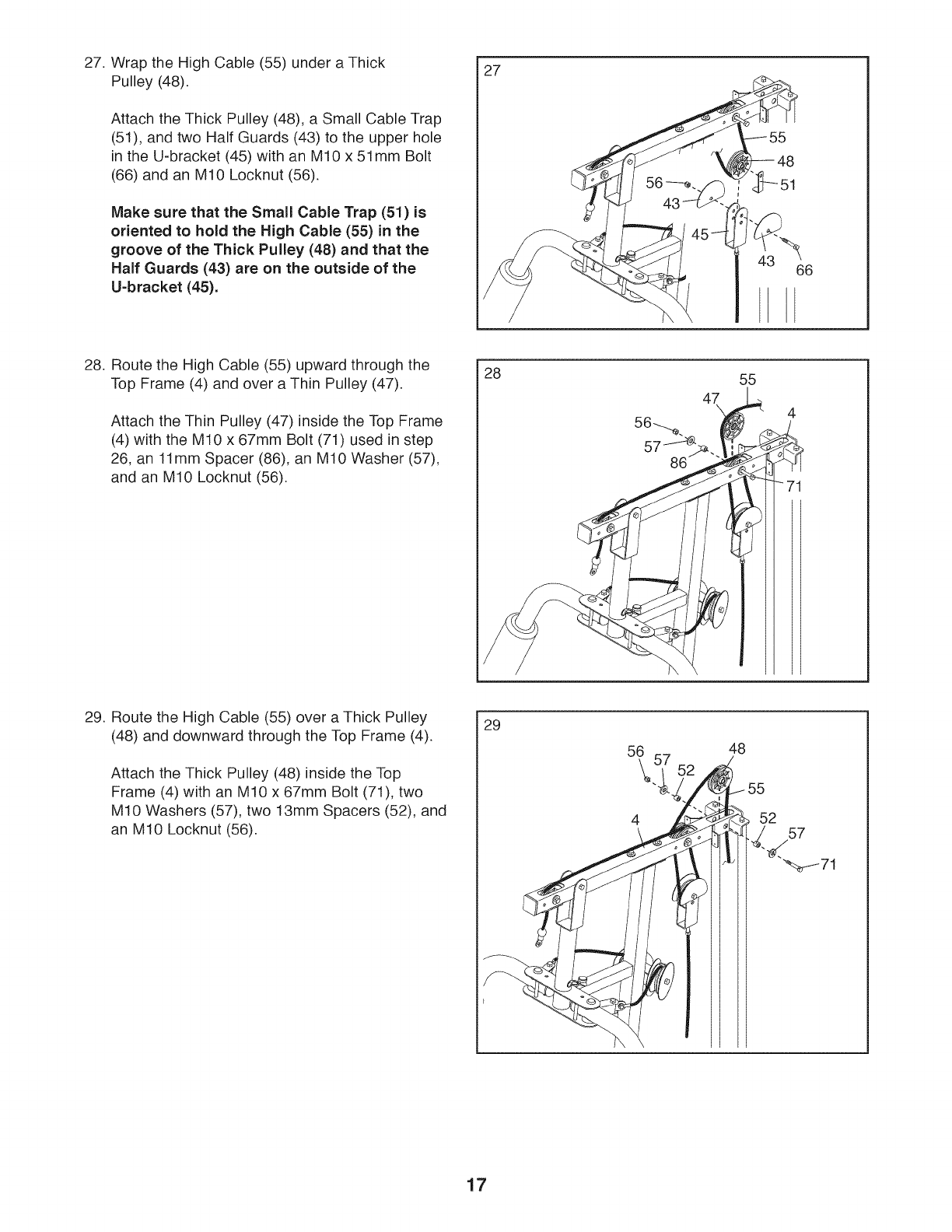
27. Wrap the High Cable (55) under a Thick
Pulley (48).
Attach the Thick Pulley (48), a Small Cable Trap
(51), and two Half Guards (43) to the upper hole
in the U-bracket (45) with an M10 x 51mm Bolt
(66) and an M10 Locknut (56).
Make sure that the Small Cable Trap (51) is
oriented to hold the High Cable (55) in the
groove of the Thick Pulley (48) and that the
Half Guards (43) are on the outside of the
U=bracket (45).
27
66
28. Route the High Cable (55) upward through the
Top Frame (4) and over a Thin Pulley (47).
Attach the Thin Pulley (47) inside the Top Frame
(4) with the M10 x 67mm Bolt (71) used in step
26, an 11mm Spacer (86), an M10 Washer (57),
and an M10 Locknut (56).
28
47\
55
4
71
29. Route the High Cable (55) over a Thick Pulley
(48) and downward through the Top Frame (4).
Attach the Thick Pulley (48) inside the Top
Frame (4) with an M10 x 67mm Bolt (71), two
M10 Washers (57), two 13mm Spacers (52), and
an M10 Locknut (56).
29
56
4\
48
_52 57
" ._.
"_/71
17
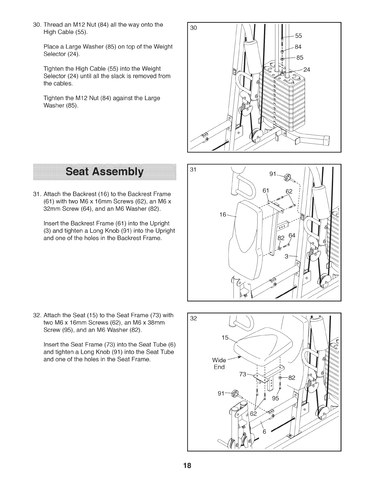
30. Thread an M12 Nut (84) all the way onto the
High Cable (55).
Place a Large Washer (85) on top of the Weight
Selector (24).
Tighten the High Cable (55) into the Weight
Selector (24) until all the slack is removed from
the cables.
Tighten the M12 Nut (84) against the Large
Washer (85).
30
31. Attach the Backrest (16) to the Backrest Frame
(61) with two M6 x 16mm Screws (62), an M6 x
32mm Screw (64), and an M6 Washer (82).
Insert the Backrest Frame (61) into the Upright
(3) and tighten a Long Knob (91) into the Upright
and one of the holes in the Backrest Frame.
31
32. Attach the Seat (15) to the Seat Frame (73) with
two M6 x 16mm Screws (62), an M6 x 38mm
Screw (95), and an M6 Washer (82).
Insert the Seat Frame (73) into the Seat Tube (6)
and tighten a Long Knob (91) into the Seat Tube
and one of the holes in the Seat Frame.
32
Wide
End
18
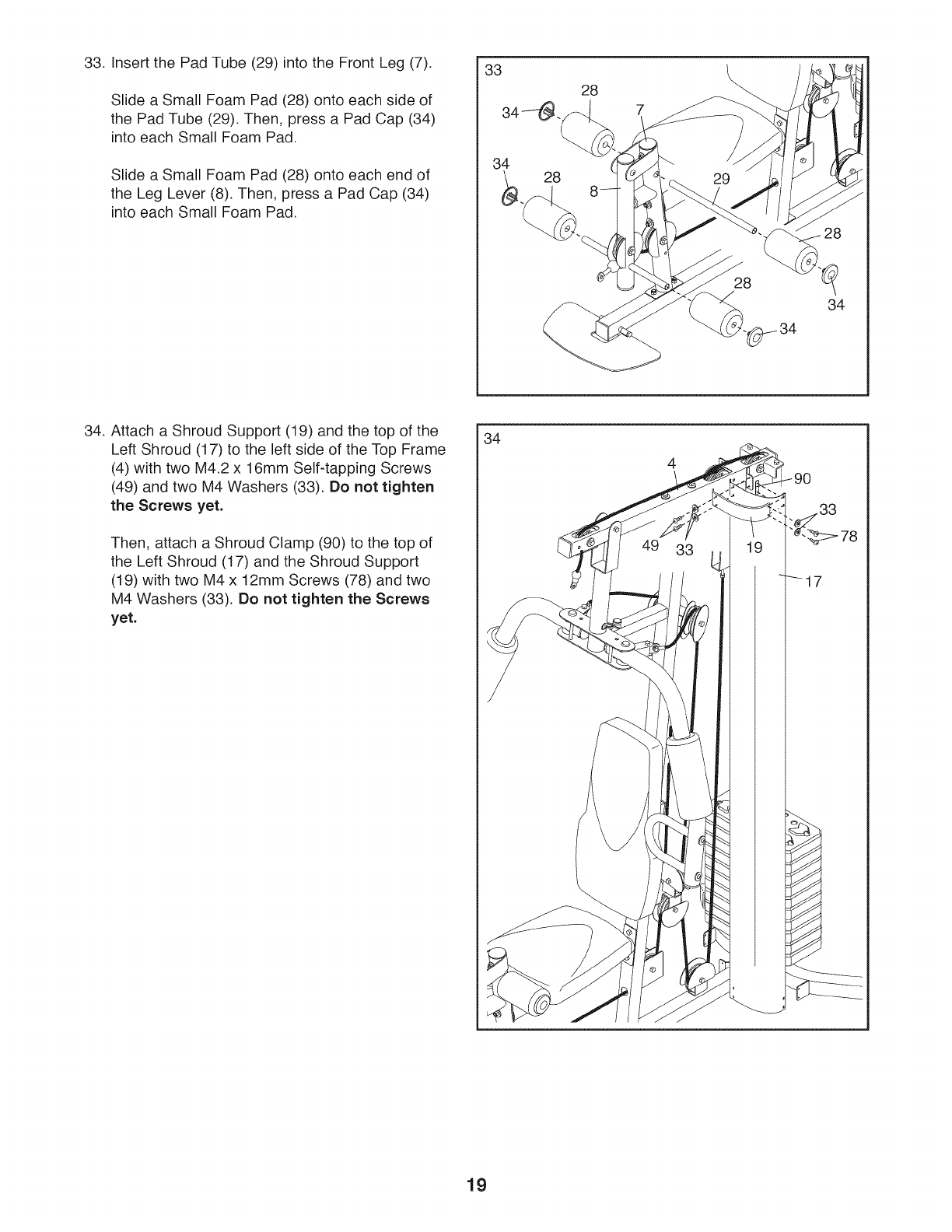
33. Insert the Pad Tube (29) into the Front Leg (7).
Slide a Small Foam Pad (28) onto each side of
the Pad Tube (29). Then, press a Pad Cap (34)
into each Small Foam Pad.
Slide a Small Foam Pad (28) onto each end of
the Leg Lever (8). Then, press a Pad Cap (34)
into each Small Foam Pad.
7
34 28
28
34
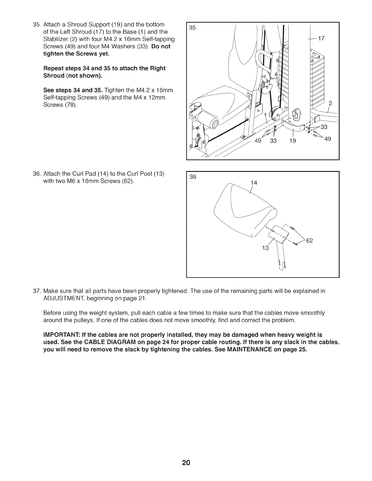
34. Attach a Shroud Support (19) and the top of the
Left Shroud (17) to the left side of the Top Frame
(4) with two M4.2 x 16mm Self-tapping Screws
(49) and two M4 Washers (33). Do not tighten
the Screws yet.
Then, attach a Shroud Clamp (90) to the top of
the Left Shroud (17) and the Shroud Support
(19) with two M4 x 12mm Screws (78) and two
M4 Washers (33). Do not tighten the Screws
yet.
34
17
19
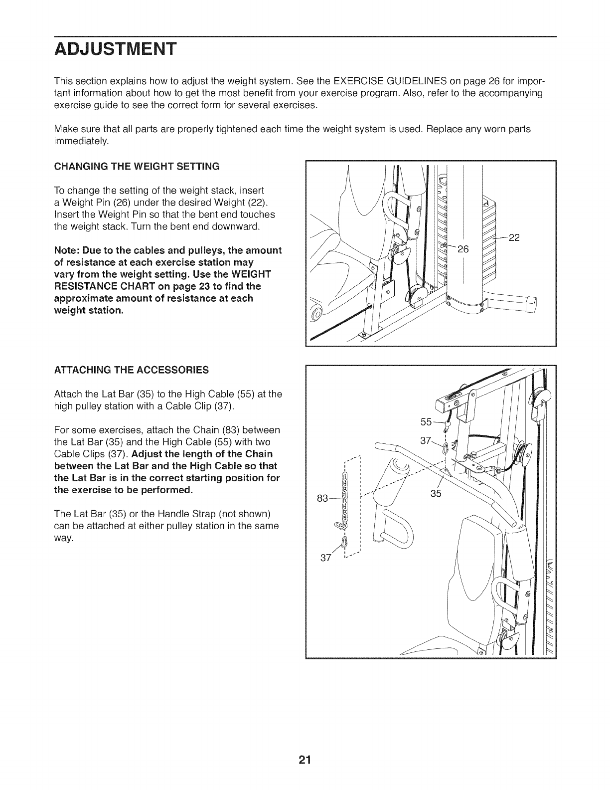
35. Attach a Shroud Support (19) and the bottom
of the Left Shroud (17) to the Base (1) and the
Stabilizer (2) with four M4.2 x 16mm Self-tapping
Screws (49) and four M4 Washers (33). Do not
tighten the Screws yet.
Repeat steps 34 and 35 to attach the Right
Shroud (not shown).
See steps 34 and 35. Tighten the M4.2 x 16mm
Self-tapping Screws (49) and the M4 x 12mm
Screws (78).
35
49 33 19 49
36. Attach the Curl Pad (14) to the Curl Post (13)
with two M6 x 16mm Screws (62). 36 14
13
37. Make sure that all parts have been properly tightened. The use of the remaining parts will be explained in
ADJUSTMENT, beginning on page 21.
Before using the weight system, pull each cable a few times to make sure that the cables move smoothly
around the pulleys. If one of the cables does not move smoothly, find and correct the problem.
iMPORTANT: if the cables are not properly installed, they may be damaged when heavy weight is
used. See the CABLE DIAGRAM on page 24 for proper cable routing, if there is any slack in the cables,
you will need to remove the slack by tightening the cables. See MAINTENANCE on page 25.
2O
ADJUSTMENT
This section explains how to adjust the weight system. See the EXERCISE GUIDELINES on page 26 for impor-
tant information about how to get the most benefit from your exercise program. Also, refer to the accompanying
exercise guide to see the correct form for several exercises.
Make sure that all parts are properly tightened each time the weight system is used. Replace any worn parts
immediately.
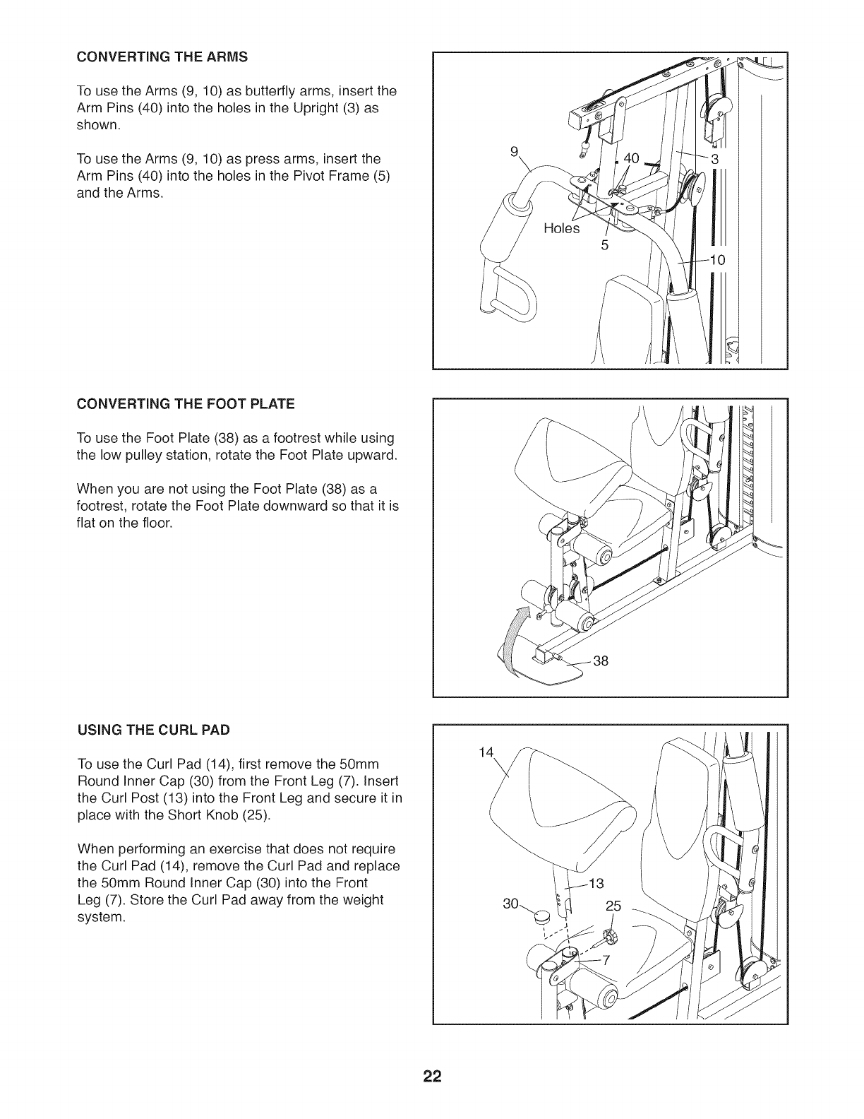
CHANGING THE WEIGHT SETTING
To change the setting of the weight stack, insert
a Weight Pin (26) under the desired Weight (22).
Insert the Weight Pin so that the bent end touches
the weight stack. Turn the bent end downward.
Note: Due to the cables and pulleys, the amount
of resistance at each exercise station may
vary from the weight setting. Use the WEIGHT
RESISTANCE CHART on page 23 to find the
approximate amount of resistance at each
weight station.
%
J
ATTACHING THE ACCESSORIES
Attach the Lat Bar (35) to the High Cable (55) at the
high pulley station with a Cable Clip (37).
For some exercises, attach the Chain (83) between
the Lat Bar (35) and the High Cable (55) with two
Cable Clips (37). Adjust the length of the Chain
between the Lat Bar and the High Cable so that
the Lat Bar is in the correct starting position for
the exercise to be performed.
The Lat Bar (35) or the Handle Strap (not shown)
can be attached at either pulley station in the same
way.
r
i
83__1 -'i
37 '"
21
CONVERTING THE ARMS
To use the Arms (9, 10) as butterfly arms, insert the
Arm Pins (40) into the holes in the Upright (3) as
shown.
To use the Arms (9, 10) as press arms, insert the
Arm Pins (40) into the holes in the Pivot Frame (5)
and the Arms.
Holes
CONVERTING THE FOOT PLATE
To use the Foot Plate (38) as a footrest while using
the low pulley station, rotate the Foot Plate upward.
When you are not using the Foot Plate (38) as a
footrest, rotate the Foot Plate downward so that it is
flat on the floor.
/
USING THE CURL PAD
To use the Curl Pad (14), first remove the 50mm
Round Inner Cap (30) from the Front Leg (7). Insert
the Curl Post (13) into the Front Leg and secure it in
place with the Short Knob (25).
When performing an exercise that does not require
the Curl Pad (14), remove the Curl Pad and replace
the 50mm Round Inner Cap (30) into the Front
Leg (7). Store the Curl Pad away from the weight
system.
14k
22
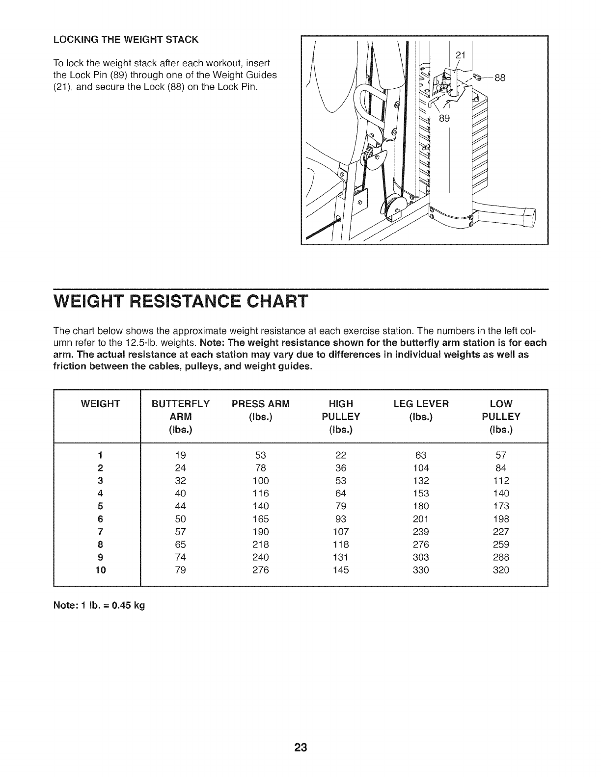
LOCKING THE WEIGHT STACK
To lock the weight stack after each workout, insert
the Lock Pin (89) through one of the Weight Guides
(21), and secure the Lock (88) on the Lock Pin.
WEIGHT RESISTANCE CHART
The chart below shows the approximate weight resistance at each exercise station. The numbers in the left col-
umn refer to the 12.5-1b. weights. Note: The weight resistance shown for the butterfly arm station is for each
arm. The actual resistance at each station may vary due to differences in individual weights as well as
friction between the cables, pulleys, and weight guides.
WEIGHT
1
2
3
4
5
6
7
8
9
10
BUTTERFLY PRESS ARM HiGH LEG LEVER LOW
ARM (Ibs.) PULLEY (Ibs.) PULLEY
(Ibs.) (Ibs.) (Ibs.)
19 53 22 63 57
24 78 36 104 84
32 100 53 132 112
40 116 64 153 140
44 140 79 180 173
50 165 93 201 198
57 190 107 239 227
65 218 118 276 259
74 240 131 303 288
79 276 145 330 320
Note: 1 lb. = 0.45 kg
23
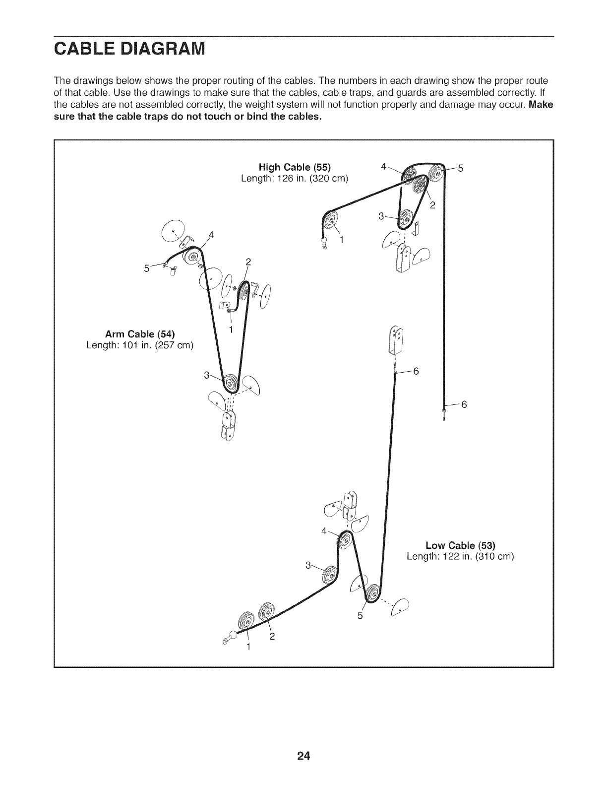
CABLE DIAGRAM
The drawings below shows the proper routing of the cables. The numbers in each drawing show the proper route
of that cable. Use the drawings to make sure that the cables, cable traps, and guards are assembled correctly. If
the cables are not assembled correctly, the weight system will not function properly and damage may occur. Make
sure that the cable traps do not touch or bind the cables.
4
Arm Cable (54)
Length: 101 in. (257 cm)
High Cable (55)
Length 126 in. (320 cm)
J6
Low Cable (53)
Length: 122 in. (310 cm)
5
24
MAINTENANCE
Make sure that all parts are properly tightened each time the weight system is used. Replace any worn parts
immediately. To clean the weight system, use a damp cloth and a mild, non-abrasive detergent; do not use sol-
vents to clean the weight system.
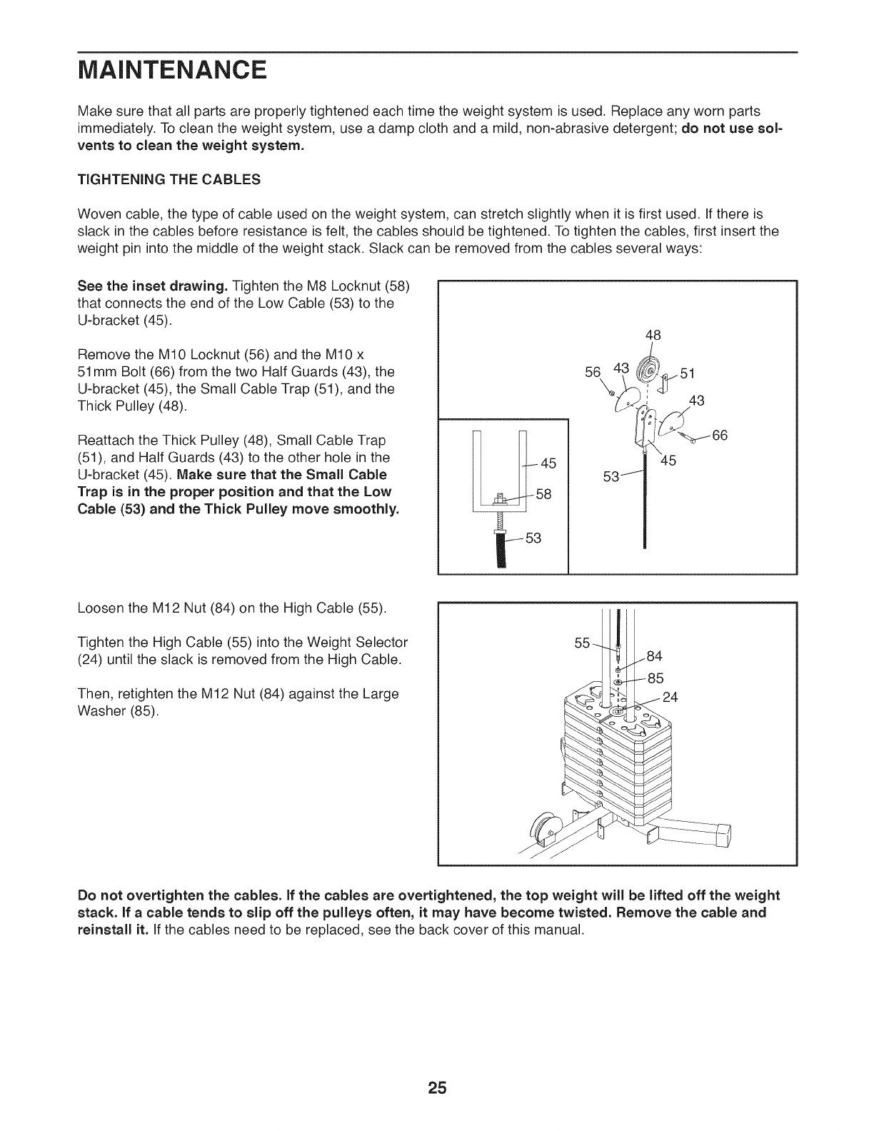
TIGHTENING THE CABLES
Woven cable, the type of cable used on the weight system, can stretch slightly when it is first used. If there is
slack in the cables before resistance is felt, the cables should be tightened. To tighten the cables, first insert the
weight pin into the middle of the weight stack. Slack can be removed from the cables several ways:
See the inset drawing. Tighten the M8 Locknut (58)
that connects the end of the Low Cable (53) to the
U-bracket (45).
Remove the M10 Locknut (56) and the M10 x
51mm Bolt (66) from the two Half Guards (43), the
U-bracket (45), the Small Cable Trap (51), and the
Thick Pulley (48).
Reattach the Thick Pulley (48), Small Cable Trap
(51), and Half Guards (43) to the other hole in the
U-bracket (45). Make sure that the Small Cable
Trap is in the proper position and that the Low
Cable (53) and the Thick Pulley move smoothly.
45
58
53J
Loosen the M12 Nut (84) on the High Cable (55).
Tighten the High Cable (55) into the Weight Selector
(24) until the slack is removed from the High Cable.
Then, retighten the M12 Nut (84) against the Large
Washer (85).
45
Do not overtighten the cables. If the cables are overtightened, the top weight will be lifted off the weight
stack. If a cable tends to slip off the pulleys often, it may have become twisted. Remove the cable and
reinstall it. if the cables need to be replaced, see the back cover of this manual.
25
EXERCISE GUiDELiNES
FOUR TYPES OF STRENGTH WORKOUTS
Note: A "repetition" is one complete cycle of an
exercise, such as one sit-up. A "set" is a series of
repetitions.
Muscle Building--Work your muscles near their maxi-
mum capacity and progressively increase the intensity
of your exercise. Adjust the intensity level of an indi-
vidual exercise as follows:
•Change the amount of resistance used.
•Change the number of repetitions or sets performed.
Use your own judgment to determine the amount of
resistance that is right for you. Begin with 3 sets of 8
repetitions for each exercise you perform. Rest for 3
minutes after each set. When you can complete 3 sets
of 12 repetitions without difficulty, increase the amount
of resistance.
Toning--Tone your muscles by working them to a
moderate percentage of their capacity. Select a moder-
ate amount of resistance and increase the number of
repetitions in each set. Complete as many sets of 15 to
20 repetitions as possible without discomfort. Rest for
1 minute after each set. Work your muscles by com-
pleting more sets rather than by using high amounts of
resistance.
Weight Loss--To lose weight, use a low amount of
resistance and increase the number of repetitions in
each set. Exercise for 20 to 30 minutes, resting for a
maximum of 30 seconds between sets.
Cross Training--Combine strength training and aero-
bic exercise by following this type of program:
•Strength training workouts on Monday, Wednesday,
and Friday.
•20 to 30 minutes of aerobic exercise on Tuesday and
Thursday.
•One full day of rest each week to give your body time
to regenerate.
WORKOUT GUIDELINES
Familiarize yourself with the equipment and learn the
proper form for each exercise. Use your own judgment
to determine the appropriate length of time for each
workout, and the numbers of repetitions and sets to
complete. Progress at your own pace and be sensitive
to your body's signals. Follow each workout with at
least one day of rest.
Warming Up--Start with 5 to 10 minutes of stretch-
ing and light exercise. A warm-up increases your body
temperature, heart rate, and circulation in preparation
for exercise.
Working Out--Include 6 to 10 different exercises in
each workout. Select exercises for every major muscle
group, emphasizing areas that you want to develop.
To give balance and variety to your workouts, vary the
exercises from workout to workout.
Cooling Down--Finish with 5 to 10 minutes of stretch-
ing. Stretching increases the flexibility of your muscles
and helps to prevent post-exercise problems.
EXERCISE FORM
Move through the full range of motion for each exer-
cise and move only the appropriate parts of the body.
Perform the repetitions in each set smoothly and
without pausing. The exertion stage of each repeti-
tion should last about half as long as the return stage.
Exhale during the exertion stage of each repetition and
inhale during the return stroke. Never hold your breath.
Rest for a short period of time after each set:
• Muscle Building--Rest for three minutes after each
set.
• Toning--Rest for one minute after each set.
• Weight Loss--Rest for 30 seconds after each set.
STAYING MOTIVATED
For motivation, keep a record of each workout. Write
the date, the exercises performed, the resistance used,
and the numbers of sets and repetitions completed.
Record your weight and key body measurements once
a month. To achieve good results, make exercise a
regular and enjoyable part of your life.
26
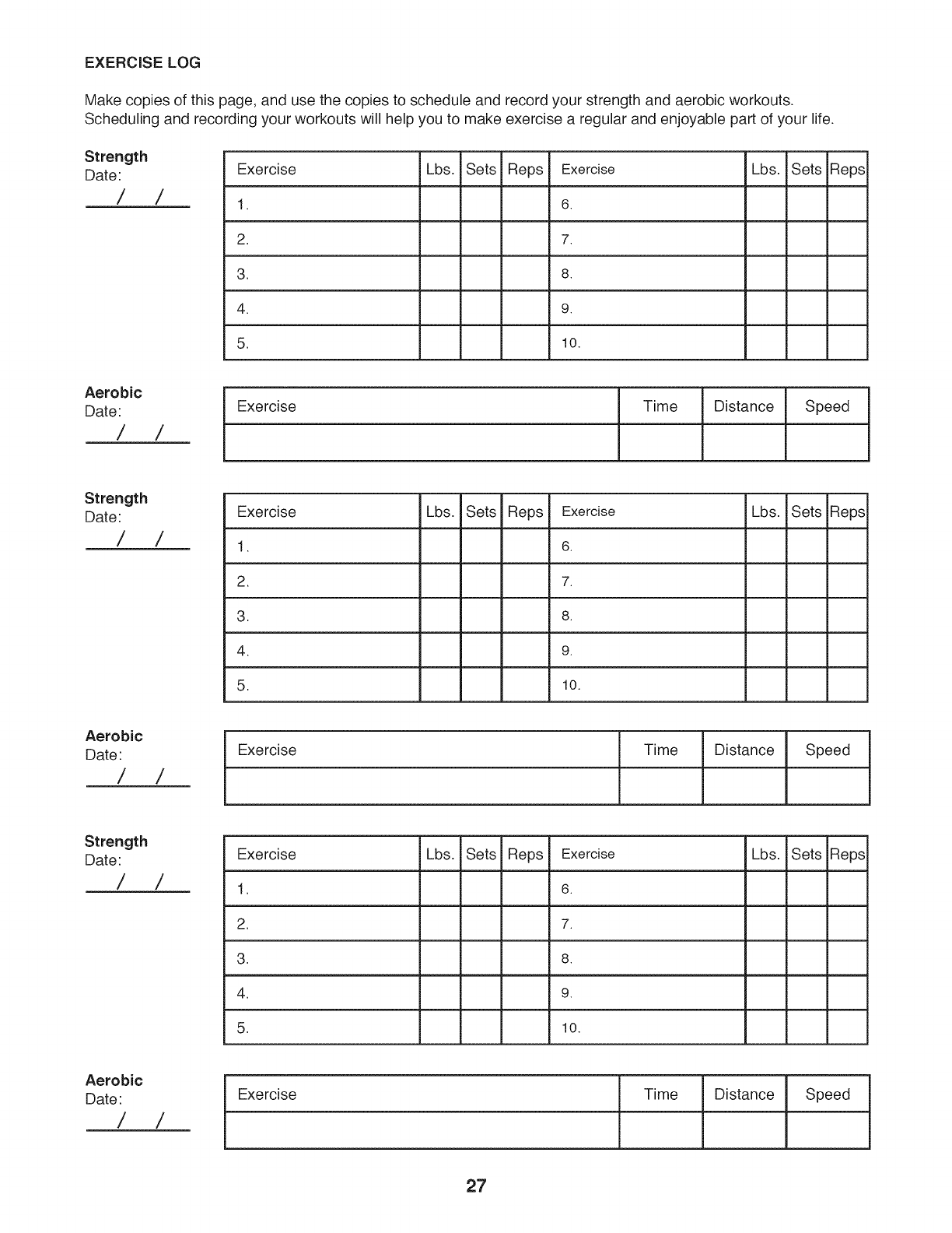
EXERCISE LOG
Make copies of this page, and use the copies to schedule and record your strength and aerobic workouts.
Scheduling and recording your workouts will help you to make exercise a regular and enjoyable part of your life.
Strength
Date:
/ /
Exercise Lbs. Sets Reps Exercise
1. 6.
2. 7.
3. 8.
4. 9.
5. 10.
Lbs. Sets Reps
Aerobic
Date:
/ /
Exercise Time Distance Speed
Strength
Date:
/ /
Aerobic
Date/ /
Exercise Lbs. Sets Reps Exercise
1. 6.
2. 7.
3. 8.
4. 9.
5. 10.
Exercise
Lbs.
Time Distance
Sets Reps
Speed
Strength
Date:
/ /
Aerobic
Date/ /
Exercise Lbs. Sets Reps Exercise
1. 6.
2. 7.
3. 8.
Lbs. Sets Reps
4. 9.
5. 10.
Exercise Time Distance Speed
27

NOTES
28
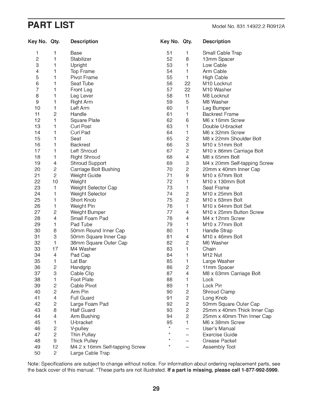
PART LIST Model No. 831.14922.2 R0912A
Key No. Qty. Description Key No. Qty. Description
1 1 Base 51 1 Small Cable Trap
2 1 Stabilizer 52 8 13mm Spacer
3 1 Upright 53 1 Low Cable
4 1 Top Frame 54 1 Arm Cable
5 1 Pivot Frame 55 1 High Cable
6 1 Seat Tube 56 22 M10 Locknut
7 1 Front Leg 57 22 M10 Washer
8 1 Leg Lever 58 11 M8 Locknut
9 1 Right Arm 59 5 M8 Washer
10 1 Left Arm 60 1 Leg Bumper
11 2 Handle 61 1 Backrest Frame
12 1 Square Plate 62 6 M6 x 16mm Screw
13 1 Curl Post 63 1 Double U-bracket
14 1 Curl Pad 64 1 M6 x 32mm Screw
15 1 Seat 65 2 M8 x 22mm Shoulder Bolt
16 1 Backrest 66 3 M10 x 51mm Bolt
17 1 Left Shroud 67 2 M10 x 86mm Carriage Bolt
18 1 Right Shroud 68 4 M8 x 65mm Bolt
19 4 Shroud Support 69 3 M4 x 20mm Self-tapping Screw
20 2 Carriage Bolt Bushing 70 2 20mm x 40mm Inner Cap
21 2 Weight Guide 71 9 M10 x 67mm Bolt
22 10 Weight 72 1 M10 x 130mm Bolt
23 1 Weight Selector Cap 73 1 Seat Frame
24 1 Weight Selector 74 2 M10 x 25mm Bolt
25 1 Short Knob 75 2 M10 x 63mm Bolt
26 1 Weight Pin 76 1 M10 x 64mm Bolt Set
27 2 Weight Bumper 77 4 M10 x 25mm Button Screw
28 4 Small Foam Pad 78 4 M4 x 12mm Screw
29 1 Pad Tube 79 1 M10 x 77mm Bolt
30 8 50mm Round Inner Cap 80 1 Handle Strap
31 3 50mm Square Inner Cap 81 4 M10 x 46mm Bolt
32 1 38mm Square Outer Cap 82 2 M6 Washer
33 17 M4 Washer 83 1 Chain
34 4 Pad Cap 84 1 M12 Nut
35 1 Lat Bar 85 1 Large Washer
36 2 Handgrip 86 2 11mm Spacer
37 3 Cable Clip 87 4 M8 x 63mm Carriage Bolt
38 1 Foot Plate 88 1 Lock
39 2 Cable Pivot 89 1 Lock Pin
40 2 Arm Pin 90 2 Shroud Clamp
41 4 Full Guard 91 2 Long Knob
42 2 Large Foam Pad 92 2 50mm Square Outer Cap
43 8 Half Guard 93 2 25mm x 40mm Thick Inner Cap
44 4 Arm Bushing 94 2 25mm x 40mm Thin Inner Cap
45 1 U-bracket 95 1 M6 x 38mm Screw
46 2 V-pulley * - User's Manual
47 2 Thin Pulley * - Exercise Guide
48 9 Thick Pulley * - Grease Packet
49 12 M4.2 x 16mm Self-tapping Screw * - Assembly Tool
50 2 Large Cable Trap
Note: Specifications are subject to change without notice. For information about ordering replacement parts, see
the back cover of this manual. *These parts are not illustrated. If a part is missing, please call 1-877-992-5999.
29
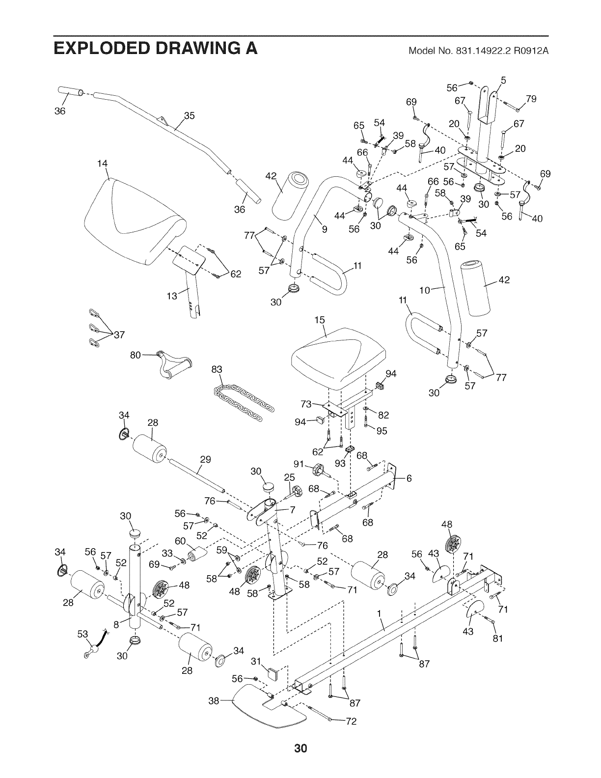
EXPLODED DRAWING A Model No. 831.14922.2 R0912A
42
36
57
9
34 56
30
15
28
30
83
29
28
11
57
30
48
56 43 71
\
77
28
28 87
43
87
72
30
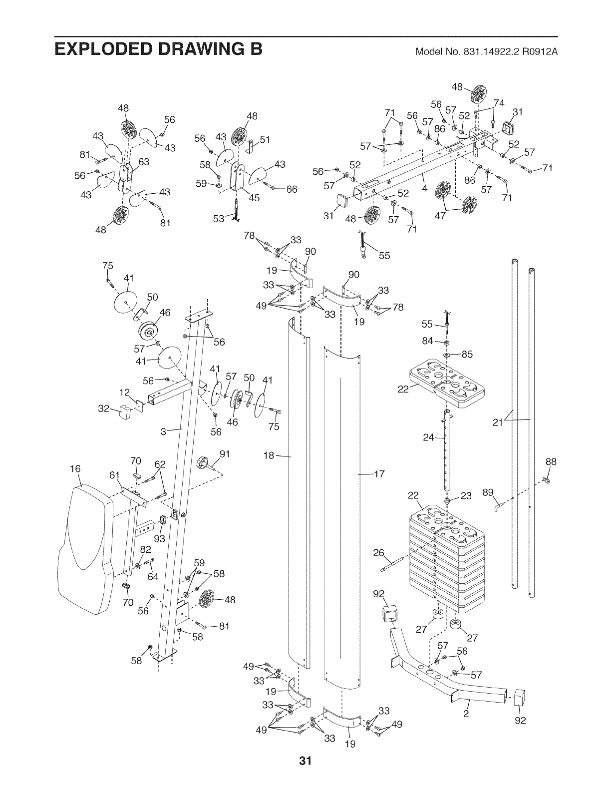
EXPLODED DRAWING BModel No. 831.14922.2 R0912A
43
16
48
56
43
48
63
81
56 4_
59----_,'i
J
53 J
56 46
7O
61
56
59 .58
48
45
75
31
71
90
33
19
47
71
88
33 19

Your Home
For repair--in your home--of all major brand appliances, lawn and garden equipment,
or heating and cooling systems, no matter who made it, no matter who sold it!
For the replacement parts, accessories, and user's manuals that you need to do-it-yourself.
For Sears professional installation of home appliances
and items like garage door openers and water heaters.
1-800-4-MY-HOME ® (1-800-469-4663)
Call anytime, day or night (U.S.A. and Canada)
www.sears.com www.sears.ca
Our Home
For repair of carry-in items like vacuums, lawn equipment,
and electronics, call or go on-line for the location of your nearest
Sears Parts & Repair Center.
1-800-488-1222 Call anytime, day or night (U.S.A. only)
www.sears.com
To purchase a protection agreement (U.S.A.)
or maintenance agreement (Canada) on a product serviced by Sears:
iiiiiiiiiiiiiiiiiii
iiiiiiiiiiiiiiiiiii
iiiiiiiiiiiiiiiiiii
iiiiiiiiiiiiiiiiiii
iiiiiiiiiiiiiiiiiii
iiiiiiiiiiiiiiiiiii
iiiiiiiiiiiiiiiiiii
iiiiiiiiiiiiiiiiiii
iiiiiiiiiiiiiiiiiii
iiiiiiiiiiiiiiiiiii
iiiiiiiiiiiiiiiiiii
iiiiiiiiiiiiiiiiiii
iiiiiiiiiiiiiiiiiii
iiiiiiiiiiiiiiiiiii
iiiiiiiiiiiiiiiiiii
iiiiiiiiiiiiiiiiiii
1-800-827-6655 (U.S.A.) 1-800-361-6665 (Canada)
Para pedir servicio de reparaci6n a domicilio, y para ordenar piezas:
.... 1-888-SU-HOGAR ®(1-888-784-6427) ..... ....
f
® Registered Trademark /TMTrademark /SMService Mark of Sears Brands, LLC
TM SM
® Marca Registrada /Marca de F&brica /Marca de Servicio de Sears Brands, LLC
90 DAY FULL WARRANTY
If this Sears Weight System Exerciser fails due to a defect in material or workmanship within 90 days of
the date of purchase, call 1-800-4-MY-HOME® (1-800-469-4663) to arrange for free repair (or replace-
ment if repair proves impossible).
This warranty does not apply when the Weight System Exerciser is used commercially or for rental pur-
poses. This warranty gives you specific legal rights, and you may also have other rights which vary from
state to state.
Sears, Roebuck and Co., Hoffman Estates, IL 60179
Part No. 338274 R0912A Printed in China © 2012 ICON IP, Inc.
