Weider 831150360 User Manual PRO 205 BENCH Manuals And Guides 99020064
WEIDER Weight System Manual 99020064 WEIDER Weight System Owner's Manual, WEIDER Weight System installation guides
User Manual: Weider 831150360 831150360 WEIDER WEIDER PRO 205 BENCH - Manuals and Guides View the owners manual for your WEIDER WEIDER PRO 205 BENCH #831150360. Home:Fitness Equipment Parts:Weider Parts:Weider WEIDER PRO 205 BENCH Manual
Open the PDF directly: View PDF ![]() .
.
Page Count: 18
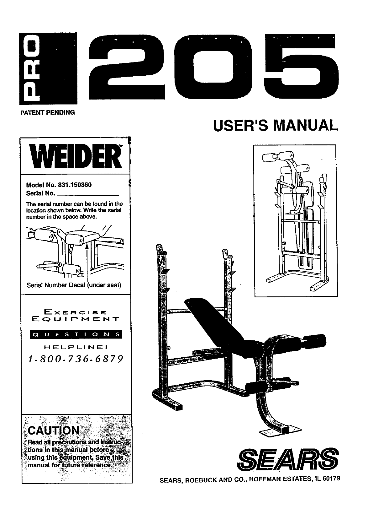
PATENTPENDING
WELDER
Model No. 831.150360
Serial No.
The sedal number can be found in the
location shown below. Wdte the serial
number in the space above.
Serial Number Decal (under seat)
HELPLINE!
/-800-736-6879
USER'S MANUAL
SFARS
SEARS, ROEBUCK AND CO., HOFFMAN ESTATES, IL 60179
TABLE OF CONTENTS
IMPORTANT PRECAUTIONS ............................................................. 2
BEFORE YOU BEGIN .................................................................. .3
PART IDENTIFICATION CHART .......................................................... .4
ASSEMBLY ........................................................................... 5
ADJUSTING.THE WELDER PRO 205 ........................................................ 9
EXERCISE GUIDELINES ................................................................ 11
PART MST ........................................................................... 14
EXPLODED DRAWING ................................................................. 15
ORDERING REPLACEMENT PARTS ................................................ Back Cover
FULL 90 DAY WARRANTY ....................................................... Back Cover
IMPORTANT PRECAUTIONS
WAHPlINU: io,reauce me riSK OXser pus Iniury; reap the lrollowln_ imDodant precautions befoi_._:_
using the weight bench.
1.,* Re_d all il'tstructions In this manuaJ_before._t_u.._Keep hands and feet away from movini] ,_arts_
' " using the,_welght bench.
"Always wear athleUc shoes for foot protec-
2. Use the weight bench only as de_ribecl]n "tion while'exercising.
this manual.
-10. The weight bench does not include weights. ,
3. Use the weight bench only on a level,surf.ace._,_'_,, The weight bench is designed to support a, ":
Cover the floor beneath, the weigh t_,benchJora_:_: maximum of 510 pounds, Including the User, L_
protection• .a weight bar and weights. Do not place more
':_=thano310 pounds, inc uding a weight bar and ,i
4.. Inspect and bghten all parts each _we|ghLs, on the we|eht rests. Do not olai:e -_,_
use,the we,ght bench. Replace an_ _-:--'more than 150 pounds on the leg lever_
part_ immediately. :._'_,_",_, _- .- -" ,. ..... ,_,.'-_',_'_
,",_:: _,+j_ l_.-When using the backrest'make sure that,the,
5. Keep small chddren ah'_ pets away,:_romi_J)_'_,_,,-adJustment tube is firmly seated in the '_',\=-_:,_
weight bench at all t.mes. ;,,adjustment brackets on the uprights. " , =_-
61 Always be.,su=re_,themjs-;_znequa!_.ap!ount_)f_._12.'lf you feal pain or dizziness at any time whlle ,___• . • .._, . ..., .._\ _.... -_, _
weight on each-side of_your barbel! (not_,_.," Lexercising; stop immediatslv and bealn cool _€
included) when you a_using IL ,:_:- ",- := ".._,_, ,_. :ing down. '., - -
,, _._
7.- When you are using the weight carrlage_ be, , 13.-:1t is the responsibility of the owner to ensure :',
sure there is an equal amount of weight on that all users of the weight bench are ade- :_¢',
each side of the weight tube. . .quately Informed of all precautions.. _:_?, =;.
WARNING. Bfffore beginning this or any exercise program;'consult your physician: This is es_l_;lly_
impo ,r,tantfor persons overthe age of _or persons with pre-existing hdalth pro'b!ems. Redid all'_._:
instruct!ons_fore usIng.,S .EARS assumes no*responsibility for personal injury or.property damaue_
sustained byor through the'use of this product•
2
BEFORE YOU BEGIN
Thank you for selecting the WELDER=PRO 205
Weight Bench. The versatile PRO 205 Weight Bench
is designed to be used with your own weight set (not
• included) to develop every major muscle group of the
body. Whether your goal is a shapely figure, dramatic
muscle size and strength, or a healthier cardiovascular
system, the PRO 205 Weight Bench will help you to
achieve the specific results you want.
For your benefit, read this manual carefully before
using the WELDERe PRO 205 Weight Bench. If you
have additional questions, please call our toll-free
HELPLINE at 1-800-736-6879, Monday through
Saturday, 7 a.m. until 7 p.m. Central "13me(excluding
holidays). To help us assist you, please note the prod-
uct model number and sedal number before calling.
The model number is 831.150360. The serial number
can be found on a decal attached to the PRO 205
Weight Bench (see the front cover of this manual).
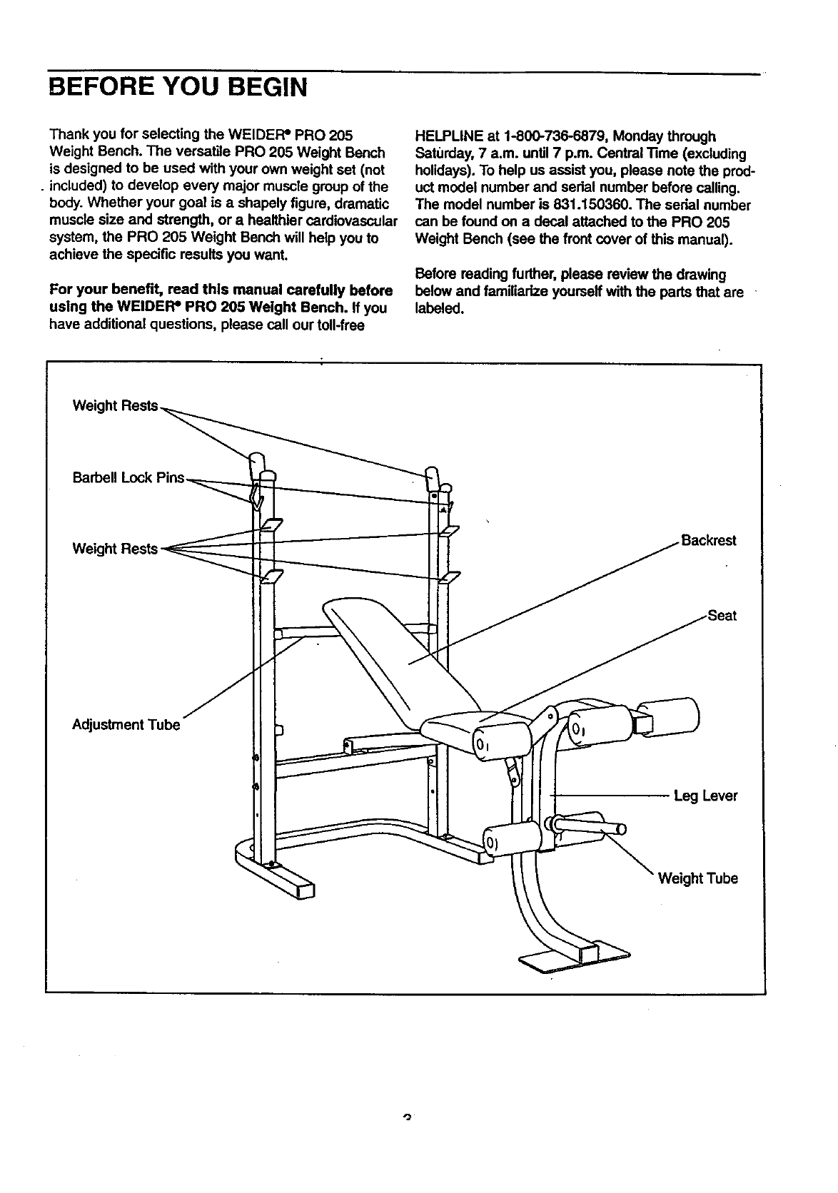
Before reading further, please review the drawing
below and familiarize yourself with the pads that are
labeled.
Barbell Lock
Adjustment Tube
Leg Lever
Weight Tube
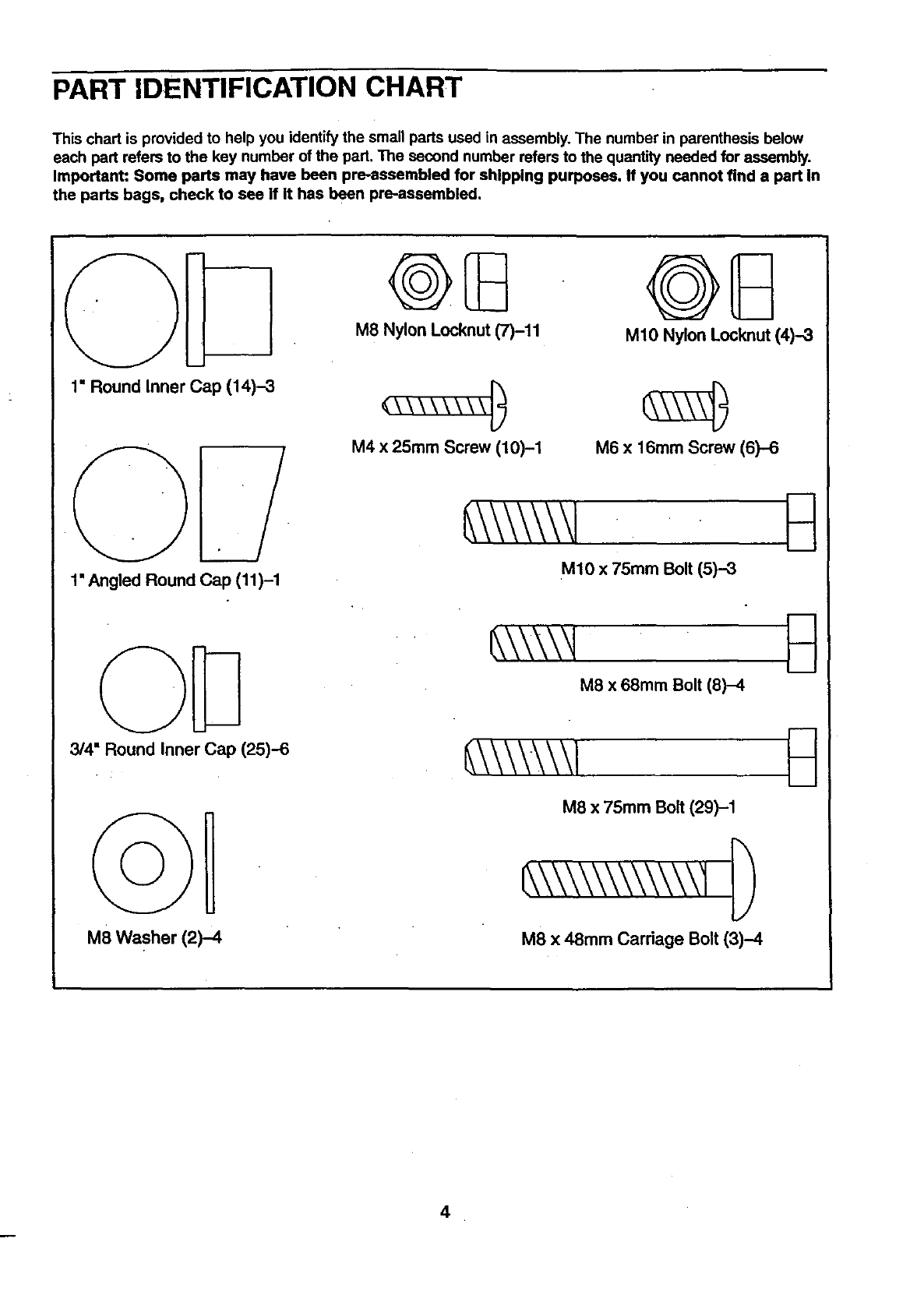
PART IDENTIFICATION CHART
This chart is provided to help you identify the small parts used in assembly. The number in parenthesis below
each part refers to the key number of the part. The second number refers to the quantity needed for assembly.
Important: Some ports may have been pre-assembled for shipping purposes. If you cannot find a part in
the parts bags, check to see if It has been pre-aseembled.
1" Round Inner Cap (14)-3
1' Angled Round Cap (11)-1
3/4" Round Inner Cap (25)-6
M8 Washer (2)-4
M8 Nylon Locknut (7)-11 M10 Nylon Locknut (4)-3
M4 x 25mm Screw (10)-1 M6 x 16mm Screw (6)-6
M10 x 75mm Bolt (5)--3
M8 x 68mm Bolt (8)-4
M8 x 75mm Bolt (29)-1
M8 x 48mm Carriage Bolt (3)-4
4
ASSEMBLY
Before beginning assembly, carefully rrad the
following Information and InstrucUons:
•Place all parts of the WELDER=PRO 205 in a
cleared area and remove the packing materials;
do not dispose of the packing materials until
assembly is completed.
• Read each assembly step before you begin.
•For help identifyingthe small parts used in
assembly, use the PART IDENTIRCATION
CHART on the previous page. Note: Some
small parts may have been pre-attached for ship-
ping purposes. If d pad is not in the pads bag,
check to see if it has been pre-attached.
• _ghten all pads as you assemble them, unless
instructed to do otherwise.
•As you assemble the WEIDEFP PRO 205, make
sure that all pads are odented as shown in the
drawings.
THE FOLLOWING TOOLS (NOT INCLUDED) ARE
REQUIRED FOR ASSEMBLY:
• Two (2) adjustable wrenches
•One (1) standard screwdriver
•One (1) rubber mallet
•Lubricant, such as grease or petroleum jelly,
and soapy water will also be needed.
Assembly will be more convenient if you have the
following tools: A socket set, a set of open-end or
closed-end wrenches, or aset of ratchet wrenches.
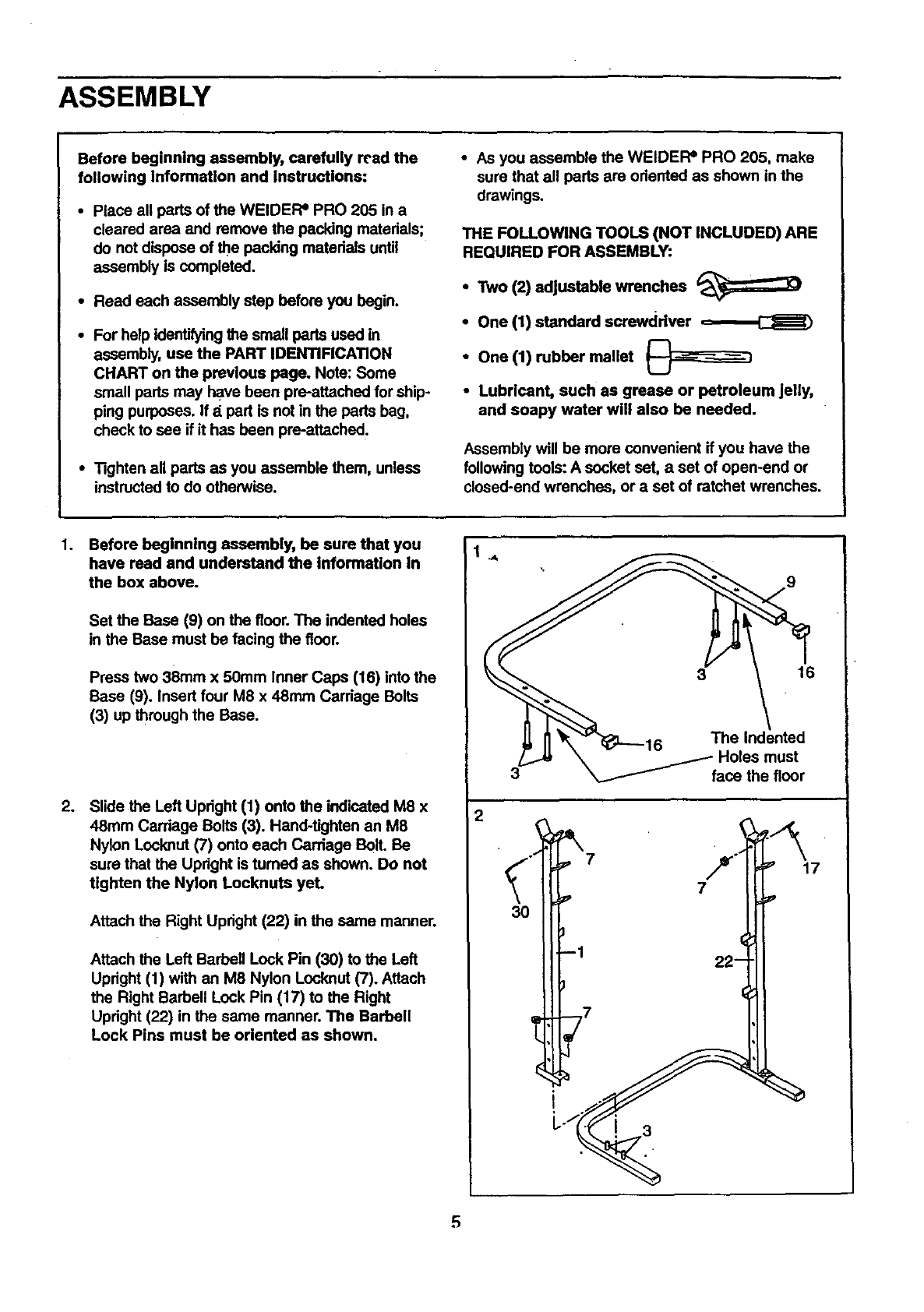
1. Before beginning assembly, be sure that you
have read and understand the Information In
the box above.
Set the Base (9) on the floor. The indented holes
in the Base must be facing the floor.
Press two 38ram x 50mm Inner Caps (16) into the
Base (9), Insert four M8 x 48ram Carriage Bolts
(3) up through the Base.
.Slide the Left Upright (1) onto the indicated M8 x
48ram Carriage Bolts (3). Hand-tighten an M8
Nylon Locknut (7) onto each Carriage Bolt. Be
sure that the Upright is tumed as shown. Do not
tighten the Nylon Locknuta yet.
Attach the Right Upright (22) in the same manner.
Attach the Left Barbell Lock Pin (30) to the Left
Upright (1) with an M8 Nylon Locknut (7). Attach
the Right Barbell Lock Pin (17) to the Right
Upright (22) in the same manner. The Barbell
Lock Pins must be oriented as shown.
16
\ -F Holes must
3_ face the floor
2
3O
7
J1
-- 22 __
L j7
L
17
5
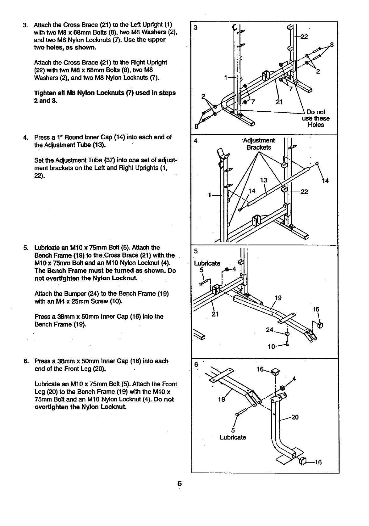
3. Attach the Cross Brace (21) to the Left Upright (1)
with two M8 x 68mm Bolts (8), two M8 Washers (2),
and two M8 Nylon Locknuts (7). Use the upper
two holes, as shown.
Attach the Cross Brace (21) to the Right Upright
(22) with two M8 x 68mm Bolts (8), two M8
Washers (2), and two M8 Nylon Locknuts (7).
Tighten all M8 Nylon Locknuts (7) used in steps
2 and 3.
.Pressa 1"RoundInnerCap (14) intoeach endof
the AdjustmentTube(13).
Set the Adjustment Tube (37) into one set of adjust-
ment brackets on the Left and Right Uprights (1,
22).
4Adjustment
Brackets
Do not
use these
Holes
o
.
Lubricate an M10 x 75mm Bolt (5). Attach the
Bench Frame (19) to theCross Brace (21) with the
M10 x 75mm Bolt and an Mt0 Nylon Locknut (4).
The Bench Frame must be tumed as shown. Do
not overtlghten the Nylon Locknut.
Attach the Bumper (24) to the Bench Frame (19)
with an M4 x 25ram Screw (10).
Press a38mm x 50mm Inner Cap (16) into the
Bench Frame (19).
Press a 38mm x 50ram Inner Cap (16) into each
end of the Front Leg (20).
Lubricate an M10 x 75mm Bolt (5). Attach the Front
Leg (20) to the Bench Frame (19) with the M10 x
75mm Bolt and an M10 Nylon Locknut (4). Do not
overUghten the Nylon Locknut.
Lubricate
21
5
Lubricate
19
16
6
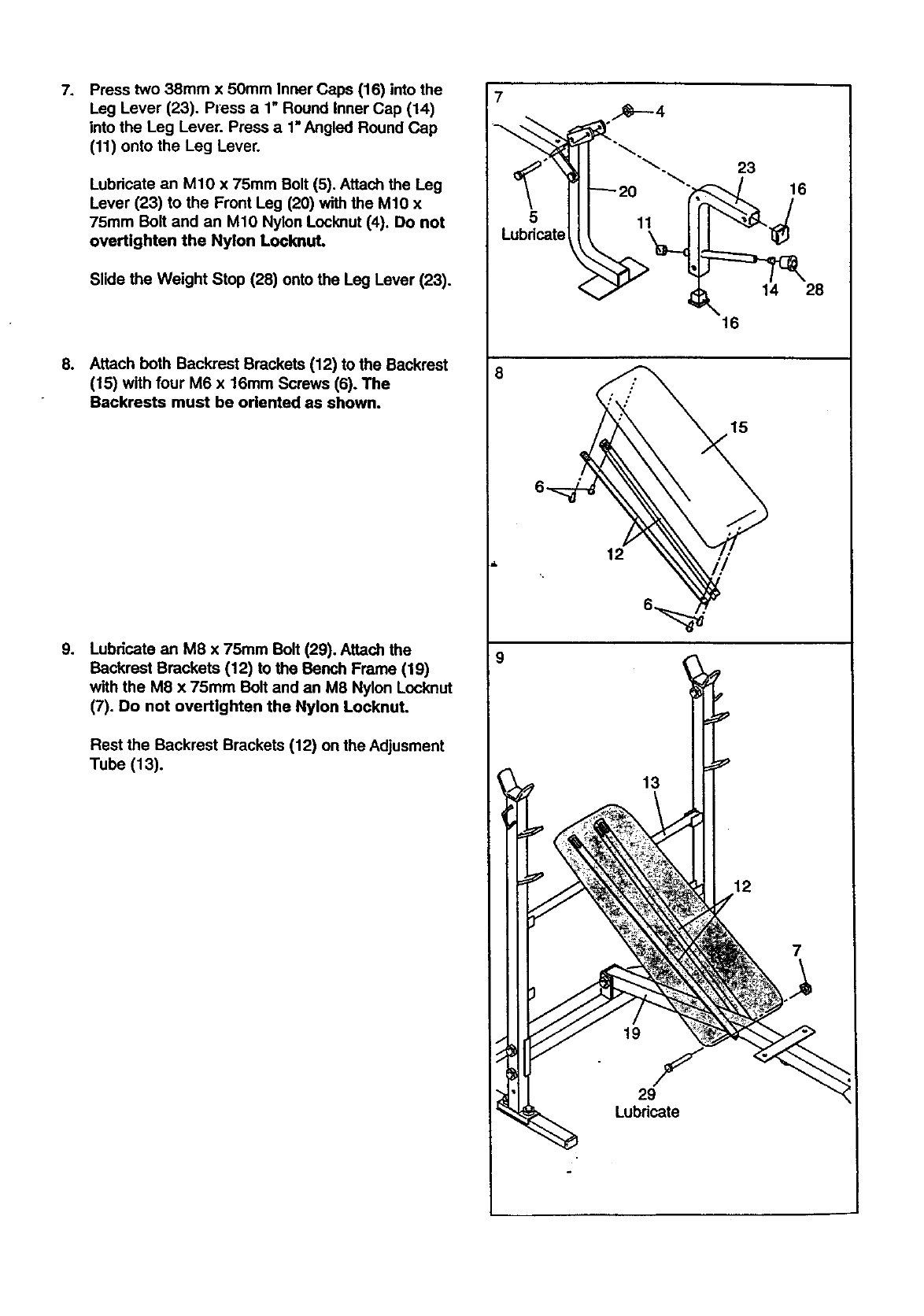
7. Press two 38mm x 50mm Inner Caps (16) into the
Leg Lever (23). Press a 1" Round Inner Cap (14)
into the Leg Lever. Press a 1=Angled Round Cap
(11) onto the Leg Lever.
Lubricate an M10 x 75mm Bolt (5). Attach the Leg
Lever (23) to the Front Leg (20) with the M10 x
75turn Bolt and an M10 Nylon Locknut (4). Do not
overtighten the Nylon Locknut.
Slide the Weight Stop (28) onto the Leg Lever (23).
8. Attach both Backrest Brackets (12) to the Backrest
(15) with four M6 x 16mm Screws (6). The
Backrests must be oriented as shown.
9. Lubricate an M8 x 75mm Bolt (29). Attach the
Backrest Brackets (12) to the Bench Frame (19)
with the M8 x 75mm Bolt and an M8 Nylon Locknut
(7). Do not overtighten the Nylon Locknut.
Rest the Backrest Brackets (12) on the Adjusment
Tube (13).
7
5
Lubricate
_20
11
23
16
16
14 28
15
12
13
7
19 F
29
Lubricate
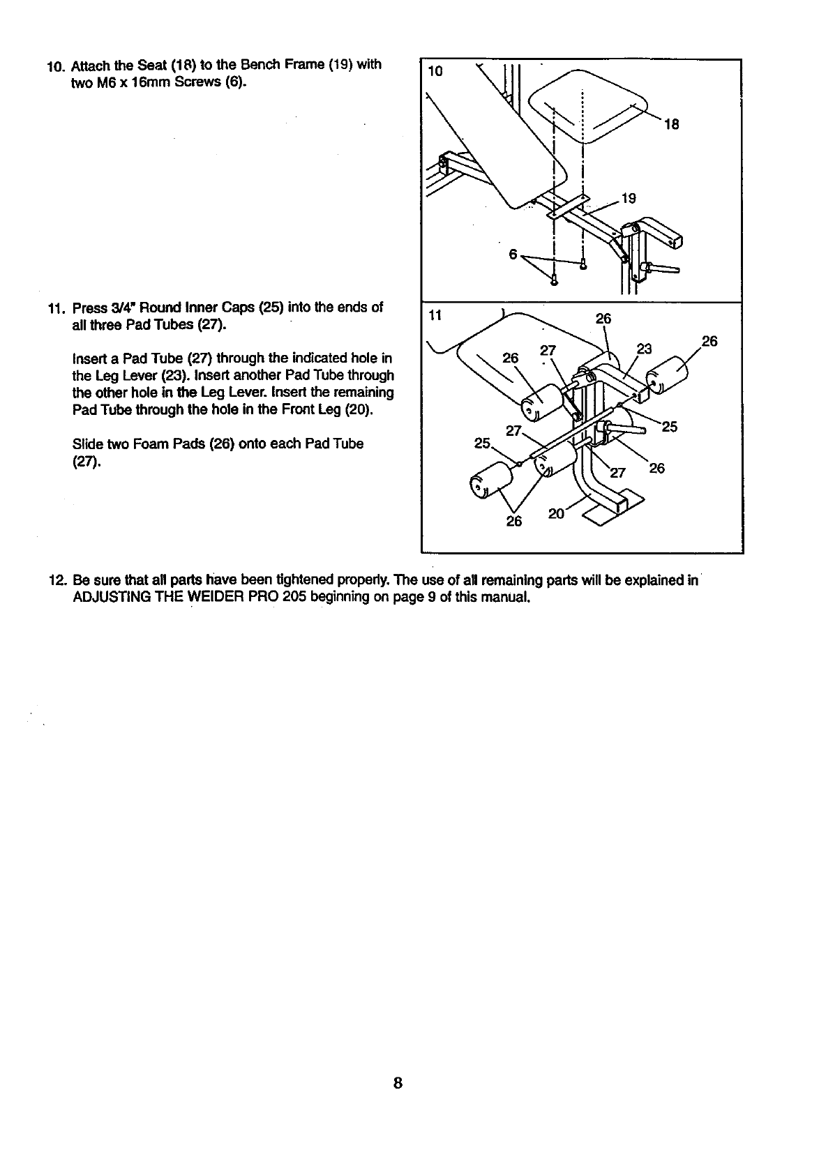
10.AttachtheSeat(18)totheBenchFrame(19)with 10 '_
twoM6x 16mmScrews(6). \
11. Press 3/4" Round Inner Caps (25) into the ends of
all three Pad Tubes (27).
Insert a Pad Tube (27) through the indicated hole in
the Leg Lever (23). Insert another Pad Tube through
the other hole in the Leg Lever. Insert the remaining
Pad Tube through the hole in the Front Leg (20),
Slide two Foam Pads (26) onto each Pad Tube
(27).
26
26
23 26
26
12. Be sure that all parts have been tightened properly.The use of all remaining pads will be explained in
ADJUSTING THE WELDER PRO 205 beginning on page 9 of this manual.
8
ADJUSTING THE WELDER PRO 205
The weight bench is designed to be used with your own weight set (not included). The steps below explain how
the weight bench can be adjusted. See EXERCISE GUIDELINES on page 11 for important exemise information
and refer to the accompanying exercise poster to see the correct form for each exercise. Refer also to the exer-
cise information accompanying your weight set (not included) for additional exercises.
Inspect and tighten all parts each time you use the weight bench. Replace any wom pads immediately. The
weight bench can be cleaned with a damp cloth and a mild, non-abrasive detergent. Do not use solvents.
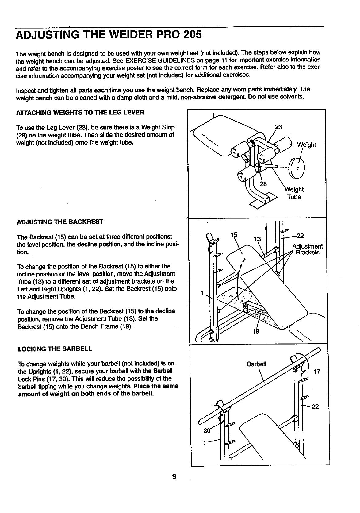
ATTACHING WEIGHTS TO THE LEG LEVER
To use the Leg Lever (23), be sure there is a Weight Stop
(28) on the weight tube. Then slide the desired amount of
weight (not included) onto the weight tube.
ADJUSTING THE BACKREST
The Backrest (15) can be set at three different positions:
the level position, the decline position, and the incline posi-
tion.
To change the position of the Backrest (15) to either the
incline position or the level position, move the Adjustment
Tube (13) to a different set of adjustment brackets on the
Left and Right Updghts (1, 22). Set the Backrest (15) onto
the Adjustment Tube.
To change the position of the Backrest (15) to the decline
position, remove the Adjustment Tube (13). Set the
Backrest (15) onto the Bench Frame (19).
LOCKING THE BARBELL
To change weights while your barbell (not included) is on
the Uprights (1, 22), secure your barbell with the Barbell
Lock Pins (17, 30). This will reduce the possibility of the
barbell tipping while you change weights. Place the same
amount of weight on both ends of the barbell.
15 13
19
Barbell
23
Weight
Tube
9
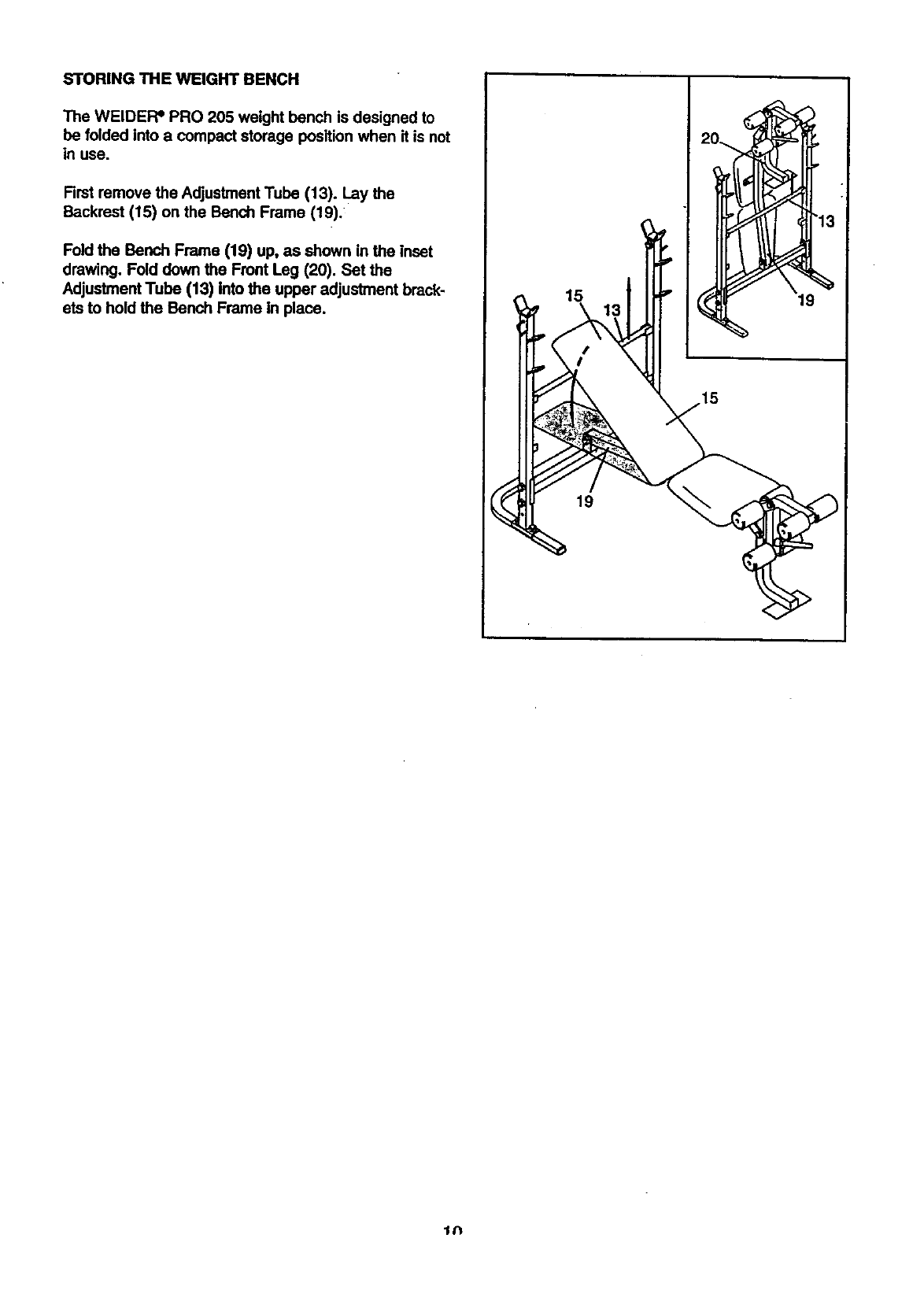
STORING THE WEIGHT BENCH
The WELDER=PRO 205 weight bench is designed to
be folded into a compact storage position when it is not
in use.
Rrst remove the Adjustment Tube (13). Lay the
Backrest (15) on the Bench Frame (19).
Fold the Bench Frame (19) up, as shown in the inset
drawing. Fold down the Front Leg (20). Set the
Adjustment Tube (13) into the upper adjustment brack-
ets to hold the Bench Frame In place. 15
19
tN
EXERCISE GUIDELINES
THE FOUR BASIC TYPES OF WORKOUTS
• Muscle Building
In order to increase the size and strength of your mus*
cles, you must push your muscles to ahigh percent-
age of their capacity. You must also progressively
increase the intensity of your exemise so that your
muscles will continually adapt and grow. Each individ-
ual exercise can be tailored to the proper intensity
level by changing the amount of weight used, or the
number of repetitions or sets performed. (A =repetition"
is one complete cycle of an exemise, such as one sit-
up. A "set" is a series of repetitions performed consec-
utively.)
The proper amount of weight for each exercise
depends upon the individual user. It is up to you to
gauge your limits. Select the amount of weight that
you think is fight for you. Begin with 3 sets of 8 repeti-
tions for each exercise that you perform. Rest for 3
minutes after each seL When you can complete 3 sets
of 12 repetitions without dift'multy,increase the amount
of weight.
• Toning
To tone your muscles, you must push your muscles to
a moderate percentage of their capacity. Select a mod-
erate amount of weight and increase the number of
repetitions in each set. Complete as many sets of 15
to 20 repetitions as possible without discomfort. Rest
for I minute after each seL Work your muscles by
completing more sets rather than by using high
amounts of weight.
• Weight Loss
To lose weight, use a low amount of weight and
increase the number of repetitions in each set.
Exemise for 20 to 30 minutes, resting for a maximum
of 30 seconds between sets.
•Cross Training
In the pursuit of a complete and well-balanced fitness
program, many have found that cress training is the
answer. We recommend that on Monday, Wednesday
and Friday, you plan weight training workouts. On
Tuesday and Thursday, plan 20 to 30 minutes of aero-
bic exercise, such as cycling, running or swimming.
Rest from both weight training and aerobic exercise for
at least one full day each week to give your body time
to regenerate. By combining weight training with aero-
bic exercise, you can reshape and strengthen your
body, plus develop a stronger heart and lungs.
PERSONALIZING YOUR EXERCISE PROGRAM
We have not specified an exact length of time for each
workout, or a specific number of repetitions or sets for
each exercise. It is very important to avoid overdoing it
during the firstfew months of your exerciseprogram,
and to progress at your own pace. If you expedence
pain or dizziness at any time while exemising, stop
immediately and begin to cool down. Find out what is
wrong before continuing. Remember that adequate
rest and a proper diet are also importanL
WARMING UP
Begin each workout with 5 to 10 minutes of light
stretching and exercise to warm up. Warming up pre-
pe_resyour body for exercise by increasing circulation,
raising your body temperature and delivering more
oxygen to your muscles.
WORKING OUT
Each workout should include 6 to 10 different exercis-
es. _etect exercises for every major muscle group,
with emphasis on the areas that you want to develop
the most. To give balance and variety to your work-
outs, vary the exercises from workout to workout.
Schedule your workoutsfor the time of day when your
energy level is the highest. Each workout should be
followed by at least one day of rest. Once you find the
schedule that is right :foryou, stick with it.
EXERCISE FORM
in order to obtain the greatest benefits from exercising,
it is essential to maintain proper form.
Maintaining proper form means moving through the full
range of motion for each exercise, and moving only
the appropriate pads of the body. Exercising in an
uncontrolled manner will leave you feeling exhausted.
On the exercise pester accompanying this manual;
you will find photographs showing the correct form for
several exercises. A description of each exercise is
also provided, along with a list of the muscles affected.
Refer to the muscle chart on page 12 to find the loca-
tions of the muscles.
The repetitions in each set should be performed
smoothly and without pausing. The exertion stage of
each repetition should last about half as long as the
ratum stage. Proper breathing is important. Exhale
during the exertion stage of each repetition and inhale
during the return stroke; never hold your breath. Rest
for 3 minutes after each set if you are doing a muscle
11
building workout, 1 minute after each set if you are
doing a toning workout, and 30 seormds after each set
you are doing a weight loss workout. Plan to spend
the firstcouple of weeks familiarizing yourself with the
equipment and leaming the proper form for each exero
rise.
COOLING DOWN
End each workout with 5 to 10 minutes of stretching.
Include stretches for both your arms and legs. Move
slowly as you stretch--do not bounce. Ease into each
stretch gradually and go only as far as you can without
strain. Stretching at the and of each workout is very
effective for increasing flexibility.
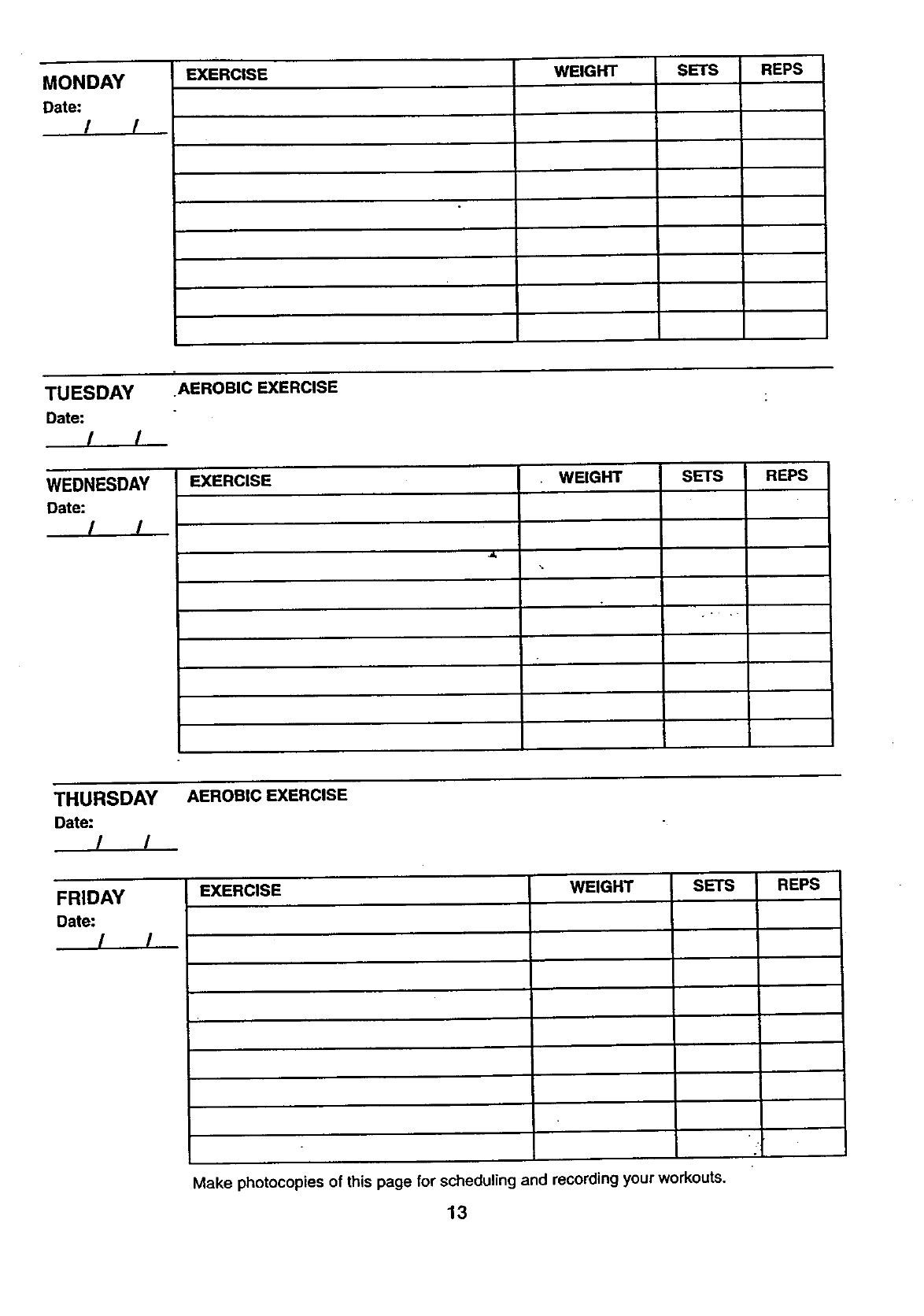
STAYING MOTIVATED
For motivation, keep a record of each workout. The
•chart on page 13 of this manual can be photocopied
and used to schedule and record your workouts. List
the date, exercises performed, weight, and numbers of
sets and repetitions completed. Record your weight
and key body measurements at the end of every
month.
Remember, the key to achieving the greatest results is
to make exercise a regular and enjoyable part of your
everyday life.
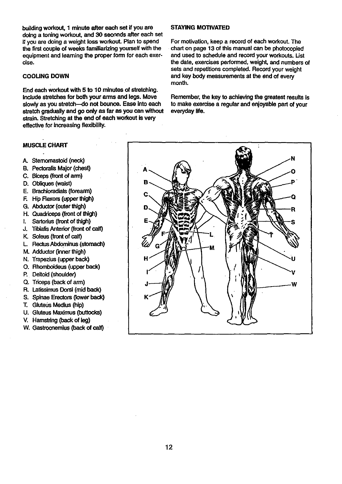
MUSCI.E CHART
A. Stemomastoid (neck)
B. PectoreHsMajor (chest)
C. Biceps (frontof arm)
D. Obliques(waist)
E. Brechioradiais(forearm)
R Hip Rexors (upper thigh)
G. Abductor (outer thigh)
H. Quaddceps (front of thigh)
I. Sartorius (front of thigh)
J. _biarB Anterior (front of call)
It,. Soleus (front of cal0
L RectusAbdominus (stomach)
M. Adductor(inner thigh)
N. Trapezius (upper back)
O. Rhomboideus (upper back)
P. Deltoid (shoulder)
Q. Triceps (back of arm)
R. Latissimus Dorsi (mid back)
S. Splnae Erectors (lower back)
T. Glute0s Medius (hip)
U. Gluteus Maximus (buttocks)
V. Hamstring (back of leg)
W. Gastrocnemius (back of calf)
c\
12
MONDAY
Date: //
EXERCISE WEIGHT SETS REPS
TUESDAY AEROBIC EXERClSE
Date: /, /
WEDNESDAY EXERCISE WEIGHT SETS REPS
Date: / !
THURSDAY
Date: ! !
FRIDAY
Date: / /
AEROBIC EXERCISE
EXERCISE 'WEIGHT SETS REPS
Make photocopies of this page for scheduling and recording your workouts.
13
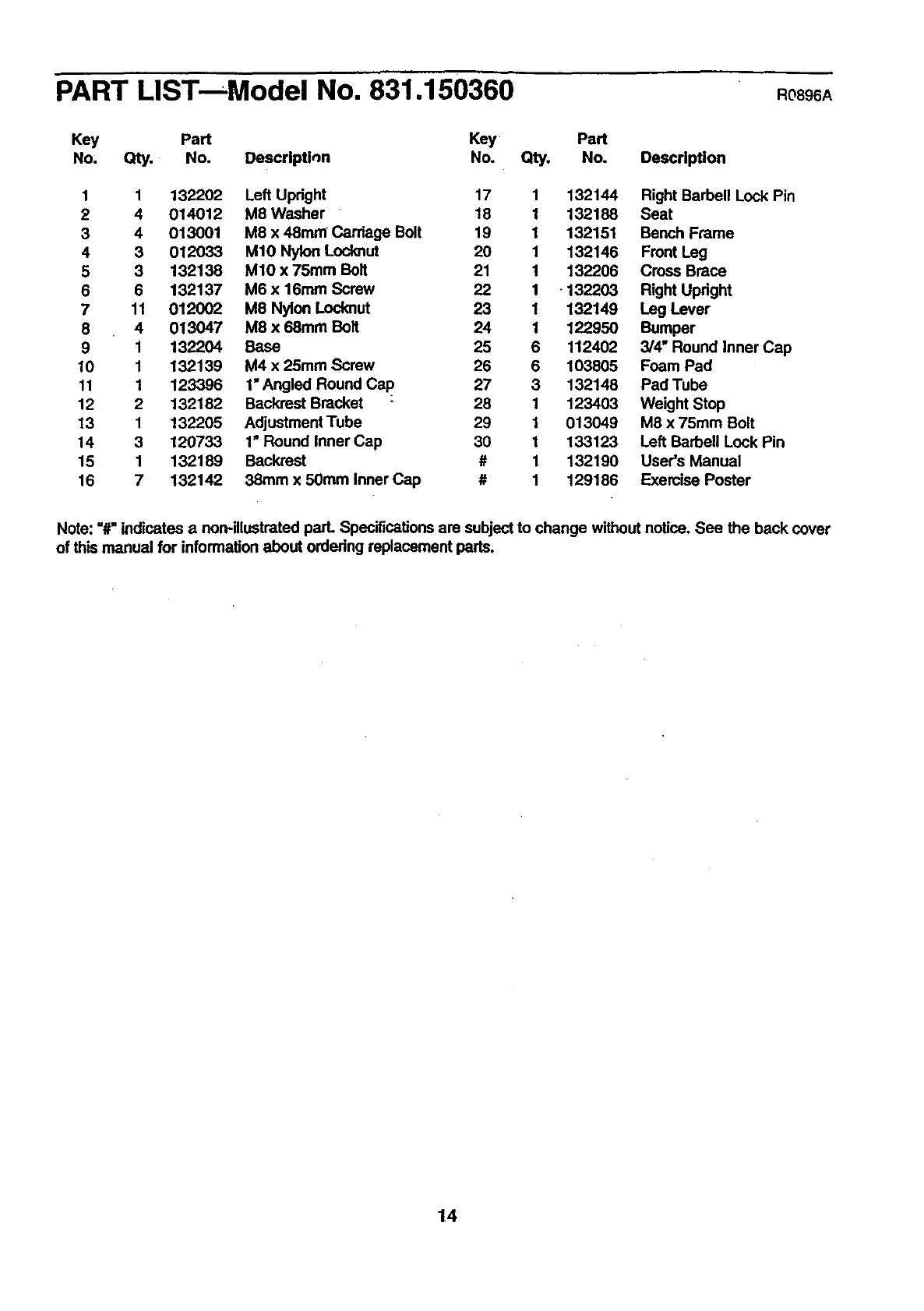
PART LISTmModel No. 831.150360 R0896A
Key Part Key Part
No, Qty. No. Descrlptl,_n No. Qty. No. Description
1 1 132202 Left Upright 17 1 132144 Right Barbell Lock Pin
24 014012 M8 Washer 18 1 132188 Seat
3 4 013001 M8 x 48mm Carriage Bolt 19 1 132151 Bench Frame
4 3 012033 M10 Nylon Locknut 20 1 132146 Front Leg
5 3 132138 M10 x 75ram Bolt 21 1 132206 Cross Brace
6 6 132137 M6 x 16mm Screw 22 1 -132203 Right Upright
7 11 012002 M8 Nylon Locknut 23 1 132149 Leg Lever
8 4 013047 M8 x 68mm Bolt 24 1 122950 Bumper
9 1 132204 Base 25 6 112402 3/4" Round Inner Cap
10 1 132139 M4 x 25ram Screw 26 6 103805 Foam Pad
11 1 123396 1"Angled Round Cap 27 3 132148 Pad Tube
12 2 132182 Backrest Bracket 28 1 123403 Weight Stop
13 1 132205 Adjustment Tube 29 1 013049 M8 x 75ram Bolt
14 3 120733 1" Round Inner Cap 30 1 133123 Left Barbell Lock Pin
15 1 132189 Backrest #1 132190 User's Manual
16 7 132142 38ram x 50ram Inner Cap #1 129186 Exercise Poster
Note: =#"indicates a non-illustrated pad. Specifications are subject to change without notice. See the back cover
of this manual for information about ordedng replacement pads.
14
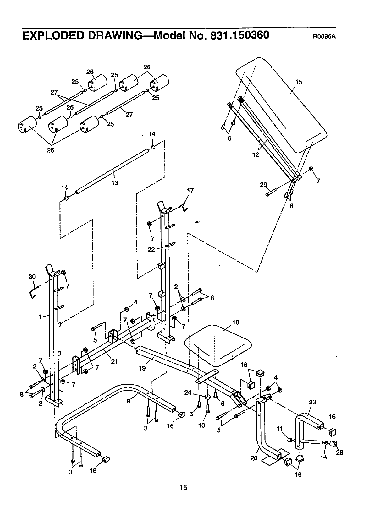
EXPLODED DRAWINGmModel No. 831.150360 Ro896A
25
3O
27
26
26
26
25
25
25
6
17
12
//'6
/
/
/
/
/
15
2
10 5
16
4
11
2O
23
16
•14
16
15

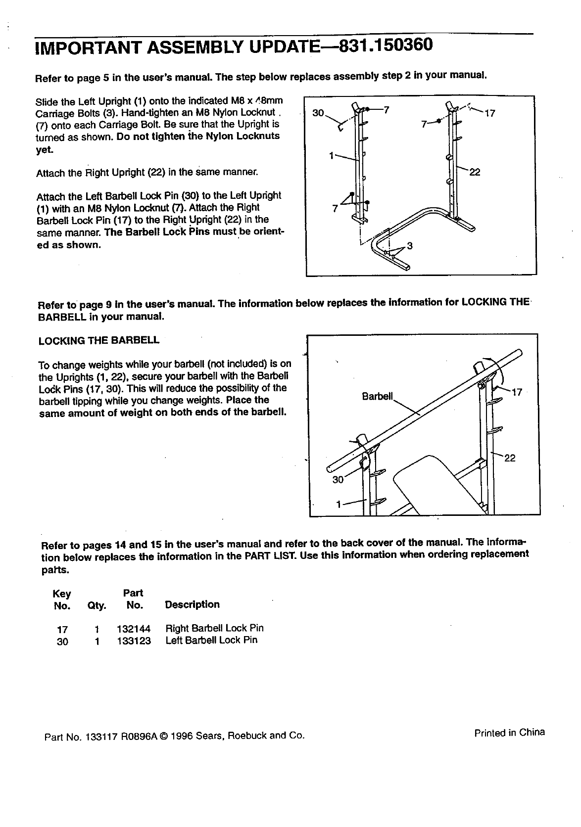
IMPORTANT ASSEMBLY UPDATE--831.150360
Refer to page 5 in the user's manual. The step below replaces assembly step 2 in your manual.
Slide the Left Updght (1) onto the indicated M8 x _,.8mm
Cardage Bolts (3). Hand-tighten an M8 Nylon Locknut
(7) onto each Cardage Bolt. Be sure that the Updght is
turned as shown. Do not tighten ihe Nylon Locknuts
yet.
Attach the Right Upright (22) in the same manner.
Attach the Left Barbell Lock Pin (30) to the Left Updght
(1) with an M8 Nylon Locknut (7). Attach the Right
Barbell Lock Pin (17) to the Right Updght (22) in the
same manner. The Barbell Lock Pins must be orient-
ed as shown.
Refer to page 9 in the user's manual. The information below replaces the information for LOCKING THE
BARBELL in your manual.
LOCKING THE BARBELL
To change weights while your barbell (not included) is on
the Updghts (1, 22), secure your barbell with the Barben
Lo_k Pins (17, 30). This witl reduce the possibility of the
barbell tipping while you change weights. Place the
same amount of weight on both ends of the barbell.
Refer to pages 14 and 15 in the user's manual and refer to the back cover of the manual. The informa-
tion below replaces the information in the PART LIST. Use this information when ordering replacement
pal'ts.
Key Part
No. Qty. No. Description
17 1 132144 Right Barbell Lock Pin
30 1 133123 Left Barbell Lock Pin
Part No. 133117 RO896A © 1996 Sears, Roebuck and Co. Printed in China
Model No. 831.150360
QUESTIONS?
If you find that:
• you need help assembUng or
operating the WELDER= PRO 205
• a part is missing
•or you need to schedule repair
service
call our toll-free HELPLINE
1-800-736-6879
Monday-Saturday, 7 am-7 pm
Central Time (excluding holidays)
REPLACEMENT
PARTS
If parts become worn and need to
be replaced, call the following toll-
free number
1-800-FON-PART
(1-800-366-7278)
The model number and serial number of your WELDER =PRO 205
are listed on a decal attached to the frame. See the front cover of
this manual to find the location of the decal.
All replacement parts are available for immediate purchase or
special order when you visit your nearest SEARS Service Center.
To request service or to order pads by telephone, call the toll-free
numbers listed at the left.
When requesting help or service, or ordering pads, please be pre-
pared to provide the following information:
• The MODEL NUMBER of the product (831.150360).
•The NAME of the product (WELDER=PRO 205 Weight Bench).
• The PART NUMBER of the PART (see the PART UST and the
EXPLODED DRAWING on pages 14 and 15 of this manual).
• The DESCRIPTION of the PART (see the PART LIST and the
EXPLODED DRAWING on pages 14 and 15 of this manual).
[ FULL 90 DAY WARRANTY 1
For 90 days from the date of purchase, if failure occurs due to defect in matadal or workmanship in this
SEARS WEIGHT BENCH EXERCISER, contact the nearest SEARS Service Center throughout the
United States and SEARS will repair or replace the WEIGHT BENCH EXERCISER, free of charge.
This warranty does not apply when the WEIGHT BENCH EXERCISER is used commemialty or for rental
purposes.
This warranty gives you specific legal dghts, and you may also have other rightswhich vary from state
to state.
SEARS, ROEBUCK AND CO., DEPT. 817WA, HOFFMAN ESTATES, IL 60179
Part No. 132i 90 R0896A Printed in China © 1996 Sears, Roebuck and Co.
