Weider 831153950 User Manual CROSSBOW Manuals And Guides L0211089
WEIDER Weight System Manual L0211089 WEIDER Weight System Owner's Manual, WEIDER Weight System installation guides
User Manual: Weider 831153950 831153950 WEIDER CROSSBOW - Manuals and Guides View the owners manual for your WEIDER CROSSBOW #831153950. Home:Fitness Equipment Parts:Weider Parts:Weider CROSSBOW Manual
Open the PDF directly: View PDF ![]() .
.
Page Count: 24
C $BOW
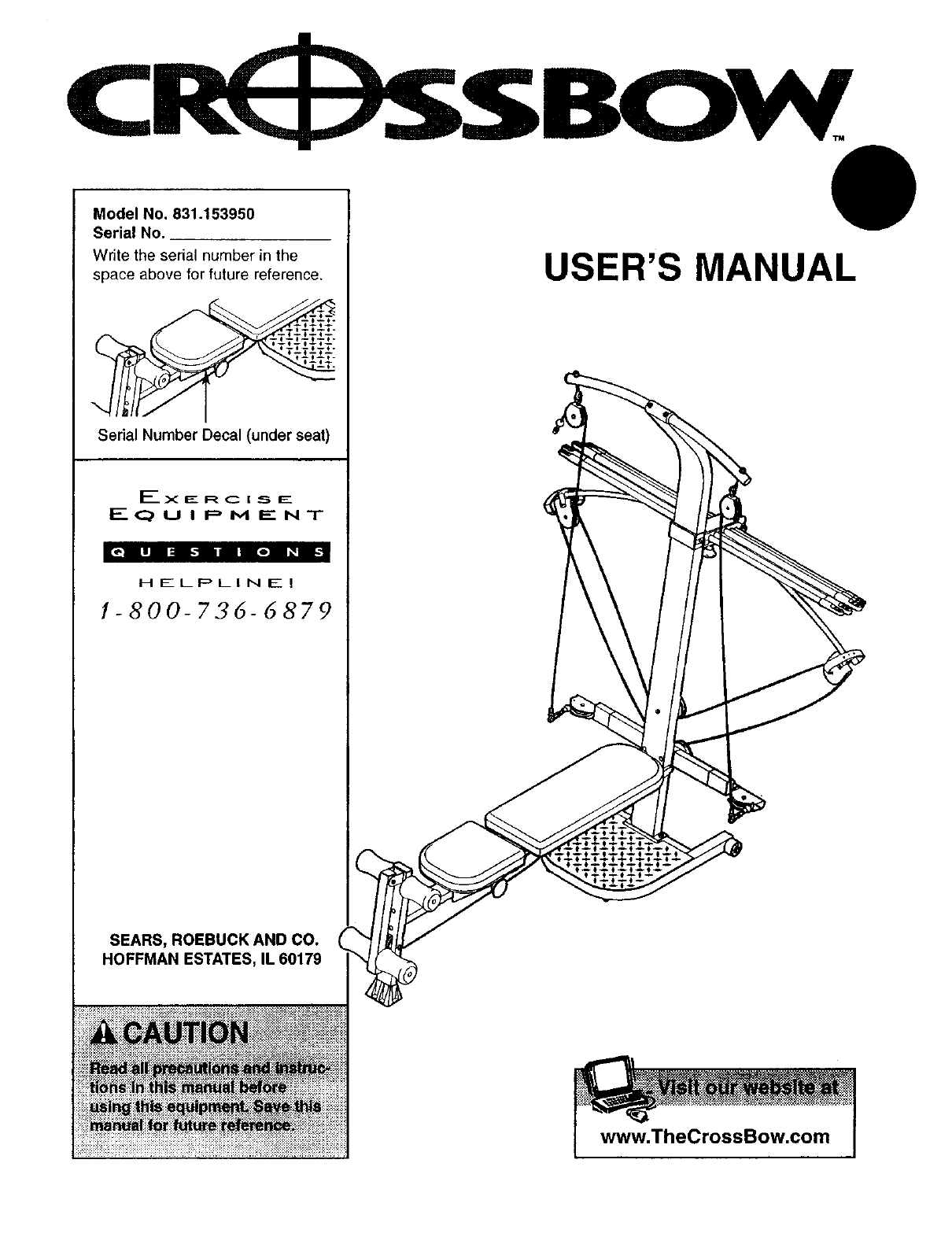
Model No. 831.153950
Serial No.
Write the serial number in the
space above for future reference.
Serial Number Decal (under seat)
F- x E_ R C i,_ _-
F---(_) UI P M E N T
rq.]
H ELI::_LI N E !
1-800-736-6879
USER'S MANUAL
SEARS, ROEBUCK AND CO.
HOFFMAN ESTATES, IL 60179
www.TheCrossBow.com

TABLE OF CONTENTS
WARNING DECAL PLACEMENT .......................................................... 2
IMPORTANT PRECAUTIONS ............................................................. 3
BEFORE YOU BEGIN ................................................................... 4
ASSEMBLY ........................................................................... 5
ADJUSTMENTS ...................................................................... 13
CABLE DIAGRAM ..................................................................... 16
EXERCISE GUIDELINES ............................................................... 17
ORDERING REPLACEMENT PARTS ................................................ Back Cover
FULL 90 DAY WARRANTY ....................................................... Back Cover
Note: A PART IDENTIFICATION CHART and aPART LIST/EXPLODED DRAWING are attached Anthe center of
this manual. Remove the PART IDENTIFICATION CHART and PART LIST/EXPLODED DRAWING before begin-
ning assembly.
WARNING DECAL PLACEMENT
The warning decals shown here
have been placed on the weight
system in the indicated loca-
tions. If a decal is missing or
illegible, please call our toll-free
HELPLINE at 1-800-736-6879,
Monday through Saturday, 7 a.m.
until 7 p.m. Central Time, to
order a free replacement decal.
Place the decal on the weight
system in the location shown.
• Keep clear of
]rea.
hands and
_a.
•Misuseof thisproductmayresultinseriousinjury.
•Readuser'smanualandfollowallwamings
andoperatingInstructionspriorto use.
•Do not allowchildrenonoraroundmachine.
removed.
CrossBow is a trademark of ICON Health & Fitness, Inc.
2

IMPORTANT PRECAUTIONS
3
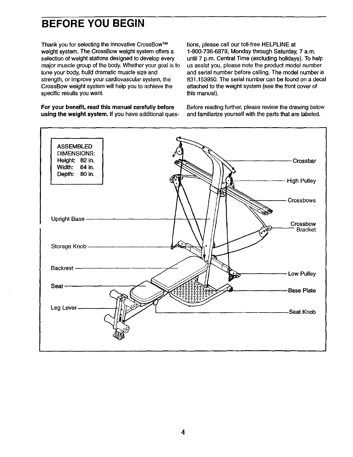
BEFORE YOU BEGIN
Thank you for selecting the innovativeCrossBow TM
weight system. The CrossBow weight system offersa
selection of weight stationsdesigned to develop every
major muscle group of the body, Whether your goal is to
tone your body, build dramatic muscle size and
strength, or improve your cardiovascular system, the
CrossBow weight system wilt help you to achieve the
specific results you want.
For your benefit, read this manual carefully before
using the weight system. If you have additional ques-
tions, please call our toll-free HELPLINE at
1-800-736-6879, Monday through Saturday, 7 a.m.
until7 p.m. Central Time (excluding holidays). To help
us assist you, please note the product model number
and serial number before calling. The model number is
831.153950. The serial number can be found on a decal
attached to the weight system (see the front cover of
this manual).
Before reading further, please review the drawing below
and famUiarize yourself with the parts that are labeled.
ASSEMBLED
DIMENSIONS:
Height: 82 in.
Width: 64 in.
Depth: 80 in.
Upright Base
Storage Knob
Backrest
Seat
Leg Lever
Crossbar
High Pulley
Crossbows
Crossbow
Bracket
Low Pulley
•Base Plate
Seat Knob
4

ASSEMBLY
•As you assemble the weight system, make sure
all parts are oriented as shown in the drawings.
Before beginning assembly, carefully read the
following information and instructions:
•Assembly requires two persons.
•Place all parts in a cleared area and remove the
packing materials. Do not dispose of the packing
materials until assembly is completed.
• Tighten all parts as you assemble them, unless
instructed to do otherwise.
•For help identifying small parts, use the PART
IDENTIFICATION CHART in the center of this
manual
An |Allen wrench and the following tools (not
included) are required for assembly:
•Two adjustable wrenches
•One rubber mallet
•One standard screwdriver
•One Phillips screwdriver
•Lubricant, such as grease or petroleum jelly,
and soapy water.
Assembly will be more convenient if you have a
socket set, a set of open-end or closed-end
wrenches, or a set of ratchet wrenches.
1.
Attach the Upright Base (3) to the Base (1) with
two 3/8" x 2 3/4" Carriage Bolts (83) and two 3/8"
Nylon Locknuts (76) as shown.
Press two 2" Square Inner Caps (98) into the
Base (1).
Attach two Plastic Feet (53) and two Large Plastic
Feet (102) to the Base (1) with four #8 x 3/4" Tek
Screws (62).
3-_.
i
i
1\
/
i
5
2. 2
,
4,
8,
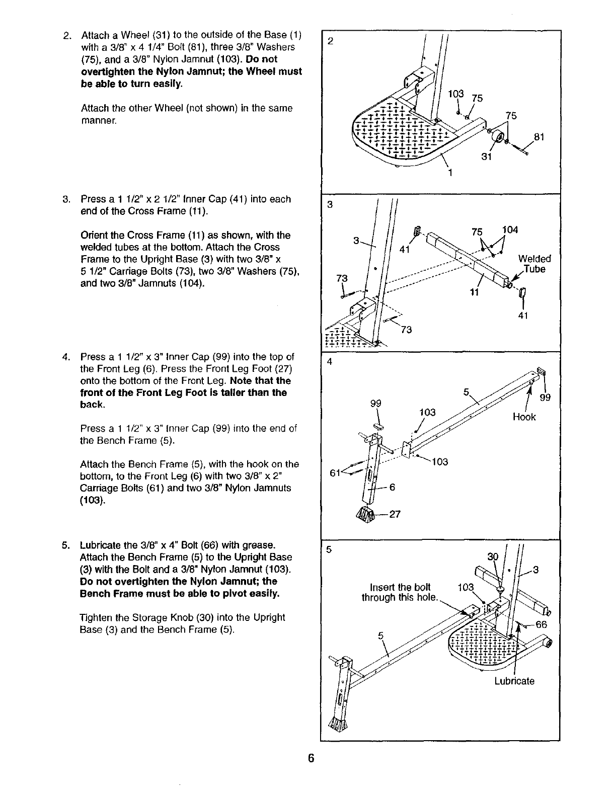
Attach a Wheel (31) to the outside of the Base (1)
with a 3/8" x 4 1/4" Bolt (81), three 3/8" Washers
(75), and a 3/8" Nylon Jamnut (103). Do not
overtighten the Nylon Jamnut; the Wheel must
be able to turn easily,
Attach the other Wheel (not shown) in the same
manner.
Press a11/2" x 2 1/2" Inner Cap (41) into each
end of the Cross Frame (11).
Orient the Cross Frame (11) as shown, with the
welded tubes at the bottom. Attach the Cross
Frame to the Upright Base (3) with two 3/8" x
5 1/2" Carriage Bolts (73), two 3/8" Washers (75),
and two 3/8" Jamnuts (104).
Press a 1 1/2" x 3" Inner Cap (99) into the top of
the Front Leg (6). Press the Front Leg Foot (27)
onto the bottom of the Front Leg. Note that the
front of the Front Leg Foot is taller than the
back,
Press a 1 1/2" x 3" Inner Cap (99) into the end of
the Bench Frame (5).
Attach the Bench Frame (5), with the hook on the
bottom, to the Front Leg (6) with two 3/8" x 2"
Carriage Bolts (61) and two 3/8" Nylon Jamnuts
(103).
Lubricate the 3/8" x 4" Bolt (66) with grease.
Attach the Bench Frame (5) to the Upright Base
(3) with the Bolt and a 3/8" Nylon Jamnut (103).
Do not overtighten the Nylon Jamnut; the
Bench Frame must be able to pivot easily.
Tighten the Storage Knob (30) into the Upright
Base (3) and the Bench Frame (5).
75
75
81
31 "_
1
3
73
75
11
104
Welded
41
4
99 103 Hook
103
_y-- 27
53O
Insert the bolt 103
through this hole.
5
Lubricate
6

6. Slide the Upright (4) into the Upright Base (3).
7.
8.
Attach the Crossbow Pivot (36) to the Upright
Base (3) and the Upright (4) with four 3/8" x 1"
Button Head Bolts (87). Insert and tighten the
bottom two Bolts first. Then, loosen the
Crossbow Knob (43) and pull it out as far as it
will go, turn the crossbow assembly to one
side or the other, and tighten the other two
Bolts. Note: It may be helpful to start all four
Bolts before tightening any of them.
When finished, turn the crossbow assembly to
the horizontal position, and tighten the
Crossbow Knob (43).
Attach the Upright Cover (89) to the Upright (4)
with two #8 x 1/2"Tek Screws (56).
Press a1 1/2" Round Inner Cap (38) into each
end of the Crossbar (10).
Attach two Eyebolts (34) to the Crossbar (10) with
two 5/16" Washers (59) and two 5/16" Jamnuts
(65). De not overtighten the Jamnuts; the
Eyebolta must be able to rotate freely.
Attach the Crossbar (10) to the Upright (4) with
two 3/8" x 3" Button Head Bolts (70), two 3/8"
Washers (75), and the Crossbar Cover (93). Be
sure that the Eyebolts (34) are oriented as
shown in the inset drawing. If they are not,
turn the Crossbar around and reattach it.
Attach the Leg Lever Bumper (55) to the Front
Leg (6) with a #8 x 3/4" Tek Screw (62).
Press two 1 3/4" Square Inner Caps (42) into the
Leg Lever (7).
Lubricate the 3/8" x 2 3/4" Button Head Bolt (64)
with grease. Orient the Leg Lever (7) as shown.
Attach the Leg Lever to the Front Leg (6) with the
Bolt and a 318" Nylon Locknut (76). Do not over-
tighten the Nylon Locknut; the Leg Lever
must be able to pivot easily.
6
%
.J
_f
56
87
Crossbow
3 Assembly
8
76
7

9. Slide a Long Spacer (46) onto a Wheel Axle (57).
Orient two Small Wheels (47) as shown in the
inset drawing, and slide them onto the ends of the
Wheel Axle. Attach the wheel assembly to one end
of the Seat Carriage (12) with a 5/16" x 4" Bolt (60)
and a 5/16" Jamnut (65) as shown. Do not over-
tighten the Jamnut; the Small Wheels must be
able to roll easily.
Attach two Small Wheels (not shown) to the other
end of the Seat Carriage (12) in the same manner.
10. Attach the Seat Knob (45) to the Seat Carriage
(12) with two #8 x1/2" Screws (92) and two #8
Nylon Locknuts (69). Be sure that the slot in the
Knob is aligned with the slot in the Seat
Carriage, as shown.
Orient the Seat (13), the Seat Backing (9), and
the Seat Carriage (12) as shown. Attach the Seat
and the Seat Backing to the Seat Cardage with
four 1/4" x 3/4" Bolts (82).
11. Pull out the Seat Knob (45) as far as it will go, and
set the Seat Carriage (12) on the Bench Frame (5).
Slide a Long Spacer (46) onto a Wheel Axle (57).
Orient two Small Wheels (47) as shown in the
inset drawing, and slide them onto the ends of the
Wheel Axle.
While a second person presses down on the Seat
(13), hold the wheel assembly firmly against the
bottom of the Bench Frame (5). Attach the wheel
assembly to the center holes in the Seat Carriage
(12) with a 5/16" x 4 1/2" Bolt (105), two Star
Washers (19), and a 5/16" Jamnut (65). Be sure
that the wide sides of all six Small Wheels (47)
are pressed against the Bench Frame.
Engage the Seat Knob (45) into an adjustment
hole in the Bench Frame (5).
9
10
11
6O
57 47
47 46
""_._. /' 57 Narrow
L.b_.._ /Side
47
Slots
105 19 13
Adjustment Hole
46 57 47
8

12. Press two 1" Square Inner Caps (54) into the indi-
cated end of the Backrest Frame (15).
Attach a Plastic Foot (53) to the Backrest Frame
(15) with a #8 x 3/4" Tek Screw (62).
Attach the two Guard Plates (17) to the inside of
the Bench Frame (15) with four #8 x 1/2" Tek
Screws (56).
13. Orient the Backrest (14) and the Backrest
Backing (8) as shown. Attach the Backrest and
the Backrest Backing to the Backrest Frame (15)
with four 1/4" x 1 3/4" Bolts (58).
14. Insert the rod on the Backrest Frame (15) into the
slot in the Seat Carriage (12). Hold the Backrest
Frame vertically over the Seat Carriage and
slide the rod into the slot, as shown in the
inset drawing.
15. Locate the Long Cable (80). Insert one end of
the Cable through the welded tube on the indicat-
ed end of the Cross Frame (11) and then through
aPulley Arm (22). If necessary, use the tip of a
screwdriver to pull the end of the Cable out of the
Pulley Arm. Be sure the Cable is on the indicat-
ed side of the welded rod in the Pulley Arm,
Insert the Pulley Arm (22) into the welded tube on
the Cross Frame (11). Attach the Pulley Arm with
a #8 x 3/8" Screw (24).
Wrap the Long Cable (80) around a 90mm Pulley
(28). Attach the Pulley inside of the Pulley Arm
(22) with a 3/8" x 1 1/2" Button Head Bolt (71)
and a 3/8" Nylon Jamnut (103).
12
13
462
17
14
8
t i'
Rod
.Slot
12
71
t/ 24
,,'t/
t
Rod
103

16.WraptheLongCable(80)arounda90ramPulley
(28).AttachthePulleyanda PulleyGuard(29)to
theindicated3/8"x 5 1/2"CarriageBolt(73)with
a3/8" Nylon Locknut (76). Be sure the flat edge
of the Pulley Guard is on the side shown.
17. Remove the ends of the crossbows from the
Crossbow Brackets (39). Attach a Pulley Housing
(94) to the indicated Crossbow Bracket with a
3/8" x 4" Bolt (66), two Pivot Bushings (74), and a
3/8" Nylon Locknut (78).
Wrap the Long Cable (80) around a 90mm Pulley
(28). Attach the Pulley inside of the Pulley
Housing (94) with a 3/8" x 1 1/2" Button Head
Bolt (71) and a 3/8" Nylon Jamnut (103).
18. Wrap the Long Cable (80) under a 90mm Pulley
(28) as shown, Attach the Pulley and a Pulley
Guard (29) to the Upright Base (3) with a 3/8" x 4
1/2" Button Head Bolt (40) and e3/8" Nylon
Locknut (76). Be sure the flat edge of the
Pulley Guard is on the bottom.
19. Attach a Pulley Housing (94) to the indicated
Crossbow Bracket (39) with a 3/8" x 4" Bolt (66),
two Pivot Bushings (74), and a 3/8" Nylon
Locknut (76).
Wrap the Long Cable (80) around a90mm Pulley
(28). Attach the Pulley inside of the Pulley
Housing (94) with a 3/8" x 1 1/2" Button Head
Bolt (71) and a 3/8" Nylon Jamnut (103).
16 Flat
Edge 29 76
/
28
Crossbows
71._.
66
80
4O 76
28
Flat
Edge
19
28
10

20. Wrap the Long Cable (80) around a 90mm Pulley
(28). Attach the Pulley and a Pulley Guard (29) to
the indicated 3/8" x 5 1/2" Carriage Bolt (73) with
a3/8" Nylon Locknut (76), Be sure the flat edge
of the Pulley Guard is on the side shown.
21. Have a second person pull on the Long Cable
(80) to create slack in the Cable. Insert the end of
the Cable through the welded tube on the indicat-
ed end of the Cross Frame (11) and then through
the remaining Pulley Arm (22). Be sure the
Cable Is on the Indicated side of the welded
rod in the Pulley Arm.
Insert the Pulley Arm (22) into the welded tube on
the Cross Frame (tl). Attach the Pulley Arm with
a #8 x 3/8" Screw (24).
Wrap the Long Cable (80) around a 90mm Pulley
(28). Attach the Pulley inside of the Pulley Arm
(22) with a 3/8" x 1 1/2" Button Head Bolt (71)
and a 3/8" Nylon Jamnut (103).
22. Locate the Bench Cable (32), which has two
ends that are the same length and a third end
that is longer.
Route the longest end of the Bench Cable (32)
through the hole inthe Front Leg (6), and attach it
inside of the hole in the Leg Lever (7) with a3/8"
x 2 1/4" Button Head Bolt (63) and a 3/8" Nylon
Locknut (76).
23. Attach a 90mm Pulley (28) inside of the hole in
the Front Leg (6) with a 3/8" x 33/4" Bolt (90),
two 3/8" x 1" Spacers (52), two 3/8" Washers
(75), and a 3/8" Nylon Locknut (76). Be sure the
Pulley is above the Bench Cable (32).
Slide the two free ends of the Bench Cable (32)
onto the hook welded to the bottom of the Bench
Frame (5).
20
28
Edge
73
21
Rod_ 71 22 24/
6
7_ _76
23
6
9O
Hook
76
11

24. Locate the two Short Cables (33). Wrap one of
the Cables around a 90ram Pulley (28). Attach
the Pulley to a High Pulley Housing (21) with a
3/8" x 1 1/2" Button Head Bolt (71) and a 3/8"
Nylon Jamnut (103).
Repeat this step with the other Short Cable (33).
25. Slide the four Foam Pads (26) onto the tubes on
the Front Leg (6) and the Leg Lever (7). Press
four 1 1/4" Round Inner Caps (78) into the ends
of the tubes.
24
25
103
26
26
"i
26
26. Make sure that all parts have been properly tightened. The use of the remaining parts will be explained in
ADJUSTMENTS, beginning on the following page.
Before using the weight system, pull the long cable a few times to be sure that it moves smoothly over the
pulleys. If the cable does not move smoothly, find and correct the problem. IMPORTANT: If the cables are
not properly installed, they may be damaged when heavy weight is used. See the CABLE DIAGRAM
on page 16 for proper cable routing.
12

ADJUSTMENTS
This section explains how to adjust the weight system. See the EXERCISE GUIDELINES on page 17 for impor-
tant information about how to get the most benefit from your exercise program. Also, refer to the accompanying
exercise guide to see the correct form for each exercise.
Make sure all parts are properly tightened each time you use the weight system. Replace worn parts immediately.
The weight system can be cleaned with a damp cloth and a mild, non-abrasive detergent. Do not use solvents.
The crossbows can be cleaned with a vinyl and rubber protectant, available at an automotive or department store.
ATTACHING THE HIGH PULLEYS AND LEG LEVER
To use a high pulley, slide the hook on the High
Pulley Housing (21) onto the Eyebolt (34). Attach the
end of the Short Cable (33) without the ball to the end
of the Long Cable (80) with a Cable Clip (51). Attach
the other high pulley in the same manner.
To use the Leg Lever (not shown), attach the two
ends of the Bench Cable (32) to the ends of the Long
Cable (80) with two Cable Clips (51).
Remove the high pulleys, and detach the Bench
Cable (32), when not in use. Store the ends of the
Bench Cable on the hook under the bench frame (not
shown).
ADJUSTING THE SEAT
The Seat (13) can be secured in any of four positions
on the Bench Frame (5). To move the Seat, pull the
Seat Knob (45) out as far as it will go, and slide the
Seat to the desired position. Engage the Seat Knob
into an adjustment hole in the Bench Frame. Note: It
may be necessary to lift up on the Seat in order to
engage the Seat Knob.
To allow the Seat (13) to rollalong the Bench Frame
(5), remove the backrest from the Seat Frame (see
ADJUSTING THE BACKREST on page 14). Pull the
Seat Knob (45) out as far as it will go, and turn the
Knob so that the pin rests at the end of the "L"-
shaped slot (see the inset drawing).
12
5"L"-Slot
Pin 45
13

ATTACHING THE ACCESSORIES
To attach a Short Handle (49) to a high pulley, first
attach the high pulley to the weight system (see
AI-FACHING THE HIGH PULLEYS AND LEG LEVER
on page 13). Then, attach the Short Handle to the
Short Cable (33) with a Cable Clip (51). Repeat with
the other high pulley.
The Long Handles (not shown) or the Ankle Strap
(not shown) can be attached to the Long Cable (80)
with Cable Clips (51). Attach the Leg Press Strap (not
shown) to both ends of the Long Cable, or a lat bar to
the Short Cable (33), with two Cable Clips.
Note: A lat bar is an optional accessory for the
CrossBow. To purchase a lat bar, call our Customer
Service Department toll-free at 1-800-999-3756 and
ask for model number GNMC04420.
ADJUSTING THE RESISTANCE
To add resistance to the weight system, hold the
Crossbow Brackets (39) firmly and slide a crossbow
under them. If more resistance is needed, repeat this
process, adding one crossbow at a time.
Note: When adding resistance, always start with the
heaviest crossbow to be used, and finish with the
lightest crossbow. When removing crossbows from
the Crossbow Brackets (39), start with the lightest
crossbow and finish with the heaviest.
Additional resistance can be added to the CrossBow
weight system by calling the Customer Service
Department toll-free at 1-800-999-3756 and asking for
model number GNMC06420 (100 Pound Power Pak)
or GNMC09420 (200 Pound Power Pak).
33\
8O
Crossbows
14
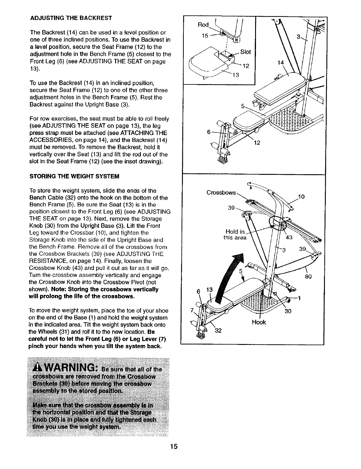
ADJUSTING THE BACKREST
The Backrest (14) can be used in a level position or
one of three inclined positions. To use the Backrest in
a level position, secure the Seat Frame (12) to the
adjustment hole in the Bench Frame (5) closest to the
Front Leg (6) (see ADJUSTING THE SEAT on page
13).
To use the Backrest (14) in an inclined position,
secure the Seat Frame (12) to one of the other three
adjustment holes in the Bench Frame (5). Rest the
Backrest against the Upright Base (3).
For row exercises, the seat must be able to roll freely
(see ADJUSTING THE SEAT on page 13), the leg
press strap must be attached (see AFIACHING THE
ACCESSORIES, on page 14), and the Backrest (14)
must be removed. To remove the Backrest, hold it
vertically over the Seat (13) and lift the rod out of the
slot in the Seat Frame (12) (see the inset drawing).
STORING THE WEIGHT SYSTEM
To store the weight system, slide the ends of the
Bench Cable (32) onto the hook on the bottom of the
Bench Frame (5). Be sure the Seat (13) is in the
position closest to the Front Leg (6) (see ADJUSTING
THE SEAT on page 13). Next, remove the Storage
Knob (30) from the Upright Base (3). Lift the Front
Leg toward the Crossbar (10), and tighten the
Storage Knob into the side of the Upright Base and
the Bench Frame. Remove all of the crossbows from
the Crossbow Brackets (39) (see ADJUSTING THE
RESISTANCE, on page 14). Finally, loosen the
Crossbow Knob (43) and pull it out as far as it will go.
Turn the crossbow assembly vertically and engage
the Crossbow Knob into the Crossbow Pivot (not
shown). Note: Storing the crossbows vertically
will prolong the life of the crossbows.
To move the weight system, place the toe of your shoe
on the end of the Base (1) and hold the weight system
in the indicated area. "131tthe weight system back onto
the Wheels (31) and rollit to the new location. Be
careful not to let the Front Leg (6) or Leg Lever (7)
pinch your hands when you tilt the system back.
Rod
15
14
12
Hold in
this area
6
3O
Hook
32
8O
15

CABLE DIAGRAM
The cable diagram shows the proper routing of the
Long Cable (80). Use the diagram to make sure that
the cable and the cable traps have been assembled
correctly. If the cable has not been correctly routed,
the weight system will not function properly and dam-
age may occur. The numbers show the correct route
for the cable. Make sure that the cable traps do
not touch or bind the cable.
J
Long Cable (80)
16

EXERCISE GUIDELINES
THE FOUR BASIC TYPES OF WORKOUTS
Muscle Building
To increase the size and strength of your muscles,
push them close to their maximum capacity. Your mus-
cles will continually adapt and grow as you progres-
sively increase the intensity of your exercise. You can
adjust the intensity level of an individual exercise in
two ways:
•by changing the amount of weight used
• by changing the number of repetitions or sets per-
formed. (A "repetition" is one complete cycle of an
exercise, such as one sit-up. A "set" is a series of
repetitions.)
The proper amount of weight for each exercise
depends upon the individual user. You must gauge
your limits and select the amount of weight that is right
for you. Begin with 3 sets of 8 repetitions for each
exercise you perform. Rest for 3 minutes after each
set. When you can complete 3 sets of 12 repetitions
without difficulty, increase the amount of weight.
Toning
You can tone your muscles by pushing them to a mod-
erate pementage of their capacity. Select a moderate
amount of weight and increase the number of repeti-
tions in each set. Complete as many sets of t 5to 20
repetitions as possible without discomfort. Rest for 1
minute after each set. Work your muscles by complet-
ing more sets rather than by using high amounts of
weight.
Weight Loss
To lose weight, use a low amount of weight and
increase the number of repetitions in each set.
Exemiee for 20 to 30 minutes, resting for a maximum
of 30 seconds between sets.
Cross Training
Cross training is an efficient way to get a complete and
well-balanced fitness program. An example of a bal-
anced program is:
•Plan weight training workouts on Monday,
Wednesday, and Friday.
•Plan 20 to 30 minutes of aerobic exercise, such as
cycling or swimming, on Tuesday and Thursday.
•Rest from both weight training and aerobic exercise
for at least one full day each week to give your body
time to regenerate.
The combination of weight training and aerobic exer-
cise will reshape and strengthen your body, plus devel-
op your heart and lungs.
PERSONALIZING YOUR EXERCISE PROGRAM
Determining the exact length of time for each workout,
as well as the number of repetitions or sets completed,
is an individual matter. It is important to avoid overdo-
ing it during the first few months of your exercise pro-
gram. You should progress at your own pace and be
sensitive to your body's signals. If you experience pain
or dizziness at any time while exercising, stop immedi-
ately and begin cooling down. Find out what is wrong
before continuing. Remember that adequate rest and a
proper diet are important factors in any exercise pro-
gram.
WARMING UP
Begin each workout with 5 to 10 minutes of stretching
and light exercise to warm up. Warming up prepares
your body for more strenuous exercise by increasing
circulation, raising your body temperature and deliver-
ing more oxygen to your muscles.
WORKING OUT
Each workout should include 6 to 10 different exercis-
es. Select exercises for every major muscle group,
emphasizing areas that you want to develop most. To
give balance and variety to your workouts, vary the
exercises from session to session.
Schedule your workouts for the time of day when your
energy level is the highest. Each workout should be
followed by at least one day of rest. Once you find the
schedule that is right for you, stick with it.
EXERCISE FORM
Maintaining proper form is an essential part of an
effective exercise program. This requires moving
through the full range of motion for each exercise, and
moving only the appropriate parts of the body.
Exercising in an uncontrolled manner will leave you
feeling exhausted. On the exercise guide accompany-
ing this manual you will find photographs showing the
correct form for several exercises, and a list of the
muscles affected. Refer to the muscle chart on page
18 to find the names of the muscles.
The repetitions in each set should be performed
smoothly and without pausing. The exertion stage of
each repetition should last about half as long as the
return stage. Proper breathing is important. Exhale
during the exertion stage of each repetition and inhale
during the return stroke. Never hold your breath.
17

Rest for a short period of time after each set. The
ideal resting periods are:
•Rest for three minutes after each set for a muscle
building workout.
• Rest for one minute after each set for a toning work-
out.
• Rest for 30 seconds after each set for a weight loss
workout.
Plan to spend the first couple of weeks familiarizing
yourself with the equipment and learning the proper
form for each exercise.
COOLING DOWN
End each workout with 5to 10 minutes of stretching.
Include stretches for both your arms and legs. Move
slowly as you stretch and do not bounce. Ease into
each stretch gradually and go only as far as you can
without strain. Stretching at the end of each workout
is an effective way to increase flexibility.
STAYING MOTIVATED
For motivation, keep a record of each workout. The
chart on page 19 of this manual can be photocopied
and used to schedule and record your workouts. List
the date, the exercises performed, the weight used,
and the numbers of sets and repetitions completed.
Record your weight and key body measurements at
the end of every month. Remember, the key to achiev-
ing the greatest results is to make exercise a regular
and enjoyable part of your everyday life.
MUSCLE CHART
A. Sternomastoid (neck)
B. Pectoralis Major (chest)
C. Biceps (front of arm)
D. Obliques (waist)
E. Brachioradials (forearm)
F. Hip Flexors (upper thigh)
G. Abductor (outer thigh)
H. Quadriceps (front of thigh)
I. Sartorius (front of thigh)
J. ]3bialis Anterior (front of calf)
K. Soleus (front of calf)
L. Rectus Abdominus (stomach)
M. Adductor (inner thigh)
N. Trapezius (upper back)
O. Rhomboideus (upper back)
P. Deltoid (shoulder)
Q. Triceps (back of arm)
R. Latissimus Dorsi (mid back)
S. Spinae Erectors (lower back)
T. Gluteus Medius (hip)
U. Gluteus Maximus (buttocks)
V. Hamstring (back of leg)
W. Gastrocnemius (back of calf)
c\
R
S
18

MONDAY EXERCISE REPS
Date:
//
WEIGHT SETS
TUESDAY
Date:
/ /
Date:
/ /
AEROBIC EXERCISE
EXERCISE WEIGHT SETS REPS
THURSDAY AEROBIC EXERCISE
Date: ! !
FRIDAY EXERCISE WEIGHT SETS REPS
Date: I /
Make photocopies of this page for scheduling and recording your workouts.
19

PART IDENTIFICATION CHART
Refer to the drawings below to identify small parts used in assembly. The number in parentheses below each
drawing is the key number of the part, from the PART LIST on the reverse side of this page. Note: Some small
parts may have been pre-attached. If a part is not in the parts bag, check to see if it has been pre-attached.
D
3/8" x 2 3/4" Button Head Bolt (64) 3/8" x 2 3/4" Carriage Bolt (83)
3/8" x 2 1/4" Button Head Bolt (63)
3/8" x 2" Carriage Bolt
1/4" x 1 3/4" Bolt (58)
3/8" x 1 1/2" Button Head Bolt (71)
_\\kk\\\/
#8 x 11/2" Bolt (77)
3/8" x 3" Button Head Bolt (70)
3/8" x 1" Button Head Bolt (87)
3/8" x 3 3/4" Bolt (90)
5116 ° x 4" Bolt {60)
3/8" x 4" Bolt(66)
3/8" x 4 1/4" Bolt (81)
5/16" x 4 1/2" Bolt (105)
1/4" x 3/4" Bolt (82)
D
3/8" x4 1/2" Button Head Bolt (40)
3/8" x 5 1/2" Carriage Bolt (73)_

3/8"NylonLocknut(76)
3/8"Jamnut(104)
©0
3/8" Nylon Jamnut (103)
f
5/16" Nylon Jamnut (65)
#8 Nylon Locknut (69)
1 1/2" Round Inner Cap (38)
1 3/4" Square Inner Cap (42)
5/16" Washer (59) 3/8" Washer (75)
#8 x 3/8" Screw (24) #8 x 1/2" Tek Screw (56)
#8 x 1/2" Screw (92) #8 x 3/4" Tek Screw (62)
1 1/4" Round Inner Cap (78) 1" Square Inner Cap (54)
1 1/2" x 2 1/2" Inner Cap (41)
_4 .u.-4 ,u-4 ,u-_
2" Square Inner Cap (98) 1 1/2" x 3" Inner Cap (99)

EXPLODED DRAWING--Model No. 831.153950 Roso2A
2O
84_
20
34
21
15
45
.57
9
17
j"
105 60\
60
5
IO0
28
66
86
,97 96
79
87 37 18
lOO
20
88
88 43
87
71
25
47
103
,103
75
78
98
103
i
,102_
62 77 83
51 22
/_ 4,
103
98 80

PART LISTmModel NO. 831.153950 Ro8o2A
Key No. Qty. Description Key No. Qty. Description
11Base 55 1 Leg Lever Bumper
2 1 Base Plate 56 8 #8 x 1/2" Tek Screw
3 1 Upright Base 57 3 Wheel Axle
4 1 Upright 58 4 1/4" x 1 3/4" Bolt
5 1 Bench Frame 59 2 5/16" Washer
6 1 Front Leg 60 2 5/16" x 4" Bolt
7 1 Leg Lever 61 2 3/8" x 2" Carriage Bolt
8 1 Backrest Backing 62 6 #8 x 314"Tek Screw
9 1 Seat Backing 63 1 3/8" x 2 1/4" Button Head Bolt
10 1 Crossbar 64 1 3/8" x 2 3/4" Button Head Bolt
11 1 Cross Frame 65 5 5/16" Jamnut
12 1 Seat Carriage 66 3 3/8" x 4" Bolt
13 1 Seat 67 1 40 Pound Crossbow
14 1 Backrest 68 2 Long Handle
15 1 Backrest Frame 69 2 #8 Nylon Locknut
16 1 Backrest Cap 70 2 3/8" x 3" Button Head Bolt
17 2 Guard Plate 71 6 3/8" x 1 1/2" Button Head Bolt
18 1 Crossbow Cardage 72 1 Crossbow Cover Plate
19 2 Star Washer 73 2 3/8" x 5 1/2" Carriage Bolt
20 4 80 Pound Crossbow Cap 74 4 Pivot Bushing
21 2 High Pulley Housing 75 12 3/8" Washer
22 2Pulley Arm 76 10 318" Nylon Locknut
23 2 Grip Tape 77 2 #8 x 1 1/2" Bolt
24 2#8 x 3/8" Screw 78 4 1 1/4" Round Inner Cap
25 4 Arm Bushing 79 210 Pound Crossbow Cap
26 4 Foam Pad 80 1Long Cable
27 1 Front Leg Foot 81 23/8" x 4 1/4" Bolt
28 10 90mm Pulley 82 4 114" x 3/4" Bolt
29 3 Pulley Guard 83 2 3/8" x 2 3/4" Carriage Boll
30 1 Storage Knob 84 2 3/16" Roll Pin
31 2 Wheel 85 10 #8 x 1/2" Flat Head Screw
32 1 Bench Cable 86 4 1/4" x 1 3/4" Button Head Screw
33 2 Short Cable 87 4 3/8" x 1" Button Head Bolt
34 2 Eyebolt 88 4 1/4" Jamnut
35 1 Crossbow Cover 89 1 Upright Cover
36 1 Crossbow Pivot 90 1 3/8" x 3 3/4" Bolt
37 2 Carriage Bushing 91 1 Retainer Ring
38 3 1 1/2" Round Inner Cap 92 2#8 x 1/2" Screw
39 2 Crossbow Bracket 93 1 Crossbar Cover
40 1 3/8" x 4 1/2" Button Head Bolt 94 2 Pulley Housing
41 21 1/2" x 21/2" Inner Cap 95 2 80 Pound Crossbow
42 2 1 3/4" Square Inner Cap 96 1 20 Pound Crossbow
43 1 Crossbow Knob 97 1 10 Pound Crossbow
44 1 15 Pound Crossbow 98 2 2" Square Inner Cap
45 1 Seat Knob 99 2 1 1/2" x 3" Inner Cap
46 3 Long Spacer 100 2 20 Pound Crossbow Cap
47 6 Small Wheel 101 2 40 Pound Crossbow Cap
48 1Leg Press Strap 102 2 Large Plastic Foot
49 2 Short Handle 103 11 3/8" Nylon Jamnut
50 1 Ankle Strap 104 23/8" Jamnut
51 4 Cable Clip 105 1 5/16" x 4 1/2" Bolt
52 2 3/8" x 1" Spacer # 1 User's Manual
53 3 Plastic Foot # 1 Exercise Guide
54 21" Square Inner Cap # 1 Exercise Decal
Note: "#" indicates a non-illustrated part, Specifications are subject to change without notice. See the back cover
of the user's manual for information about ordering replacement parts.

SEARS
Model No. 831.153950
QUESTIONS?
If you find that:
•you need help assembling or
operating the CrossBow TM
weight system
• a part is missing
•or you need to schedule repair
service
call our toll-free HELPLINE
1-800-736-6879
Monday-Saturday, 7 am-7 pm
Central Time (excluding holidays)
REPLACEMENT
PARTS
If parts become worn and need to
be replaced, call the following toll-
free number
1-800-FON-PART
(1-800-366-7278)
The model number and serial number of your CrossBow TM
weight system are listed on a decal attached to the frame. See
the front cover of this manual to find the location of the decal.
All replacement parts are available for immediate purchase or
special order when you visit your nearest SEARS Service
Center. To request service or to order parts by telephone, call the
toll-free numbers listed at the left.
When requesting help or service, or ordering parts, please be
prepared to provide the following information:
• The MODEL NUMBER of the product (831.153950)
• The NAME of the product (CrossBow TM weight system)
• The KEY NUMBER and DESCRIPTION of the PART (see the
PART LIST and EXPLODED DRAWING in the center of this
manual)
SEARS, ROEBUCK AND CO., HOFFMAN ESTATES, IL 60179
IFULL 90 DAY WARRANTY I
For 90 days from the date of purchase, if failure occurs due to defect in material or workmanship in this
SEARS WEIGHT SYSTEM EXERCISER, contact the nearest SEARS Service Center throughout the
United States and SEARS will repair or replace the WEIGHT SYSTEM EXERCISER, free of charge.
This warranty does not apply when the WEIGHT SYSTEM EXERCISER is used commercially or for
rental purposes.
This warranty gives you specific legal rights, and you may also have other rights which vary from state
to state.
SEARS, ROEBUCK AND CO., DEPT. 817WA, HOFFMAN ESTATES, IL 60179
Part No. 188045 R0802A Printed in USA@ 2002 Sears, Roebuck and Co.
