Weider 831159820 User Manual PRO 4100 Manuals And Guides L0210050
WEIDER Weight System Manual L0210050 WEIDER Weight System Owner's Manual, WEIDER Weight System installation guides
User Manual: Weider 831159820 831159820 WEIDER PRO 4100 - Manuals and Guides View the owners manual for your WEIDER PRO 4100 #831159820. Home:Fitness Equipment Parts:Weider Parts:Weider PRO 4100 Manual
Open the PDF directly: View PDF ![]() .
.
Page Count: 32
WELDERPR@4
Model No. 831.159820
Serial No.
Write the serial number in the
space above for reference.
r
Sedal Number Decal (under seat)
E_<IE_ R_ I S _
EQUIPMENT
[Olll Ill ROB _ I
HI_LPLI N E !
1-800-736-6879
USER'S MANUAL
SEARS, ROEBUCK AND CO.
HOFFMAN ESTATES, IL 60179
www.weiderfitness.com
new products, prizes,
fitness tips, and much morel
TABLE OF CONTENTS
IMPORTANT PRECAUTIONS ............................................................. 3
BEFORE YOU BEGIN ................................................................... 4
ASSEMBLY ........................................................................... 5
ADJUSTMENTS ...................................................................... 21
WEIGHT RESISTANCE CHART ........................................................... 23
CABLE DIAGRAM ..................................................................... 24
EXERCISE GUIDELINES ................................................................ 26
ORDERING REPLACEMENT PARTS ................................................ Back Cover
FULL 90 DAY WARRANTY ....................................................... Back Cover
Note: A PART IDENTIFICATION CHART and a PART LIST/EXPLODED DRAWING are attached in the center of
this manual. Remove the PART IDENTIFICATION CHART and the PART LIST/EXPLODED DRAWING before
beginning assembly.
2
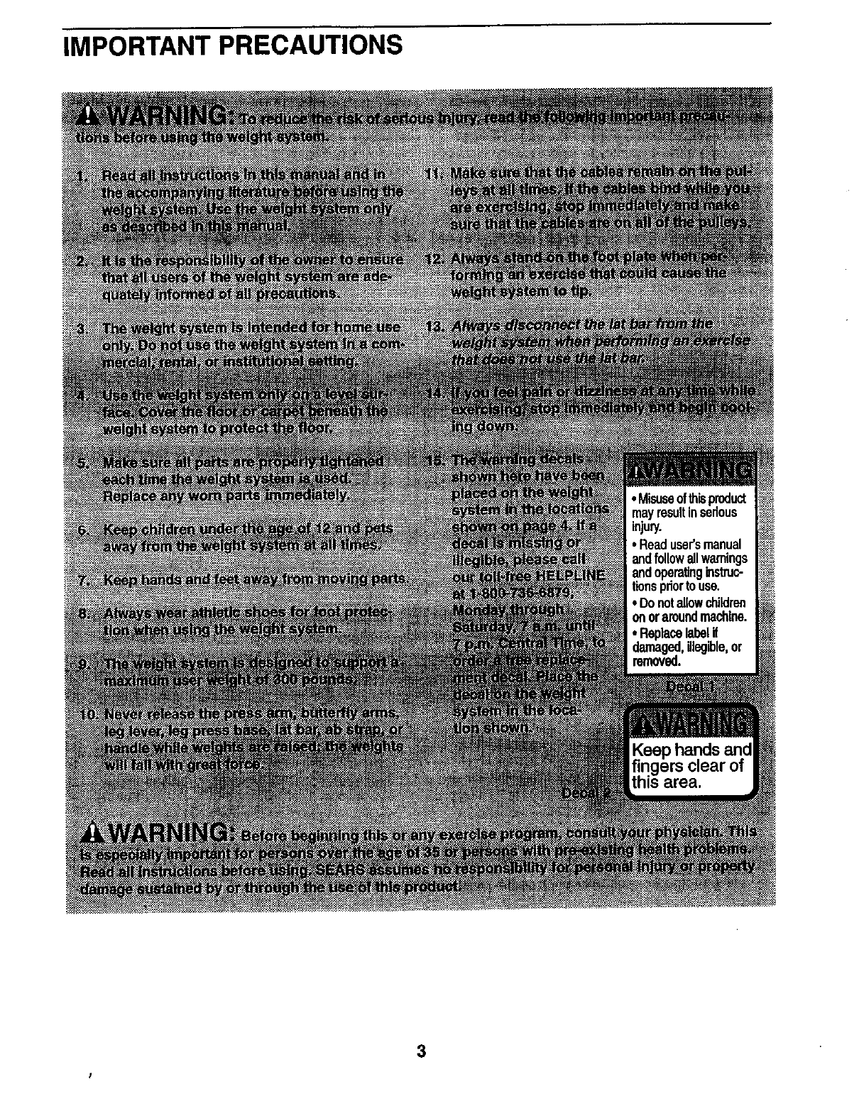
IMPORTANT PRECAUTIONS
3
BEFORE YOU BEGIN
Thank you for selecting the versatile WELDER•PRO
4100 weight system. The PRO 4100 weight system
offers a selection of weight stations designed to devel-
op every major muscle group of the body. Whether
your goal is to tone your body, build dramatic muscle
size and strength, or improve your cardiovascular sys-
tem, the weight system will help you to achieve the
results you want.
For your benefit, read this manual carefully before
using the weight system. If you have additional
questions, please call our toll-free HELPLINE at
1-800-736-6879, Monday through Saturday, 7a.m.
until 7 p.m. Central lime (excluding holidays). To help
us assist you, please note the product model number
and serial number before calling. The model number is
831.159820. The sadal number can be found on a
decal attached to the weight system (see the front
cover of this manual).
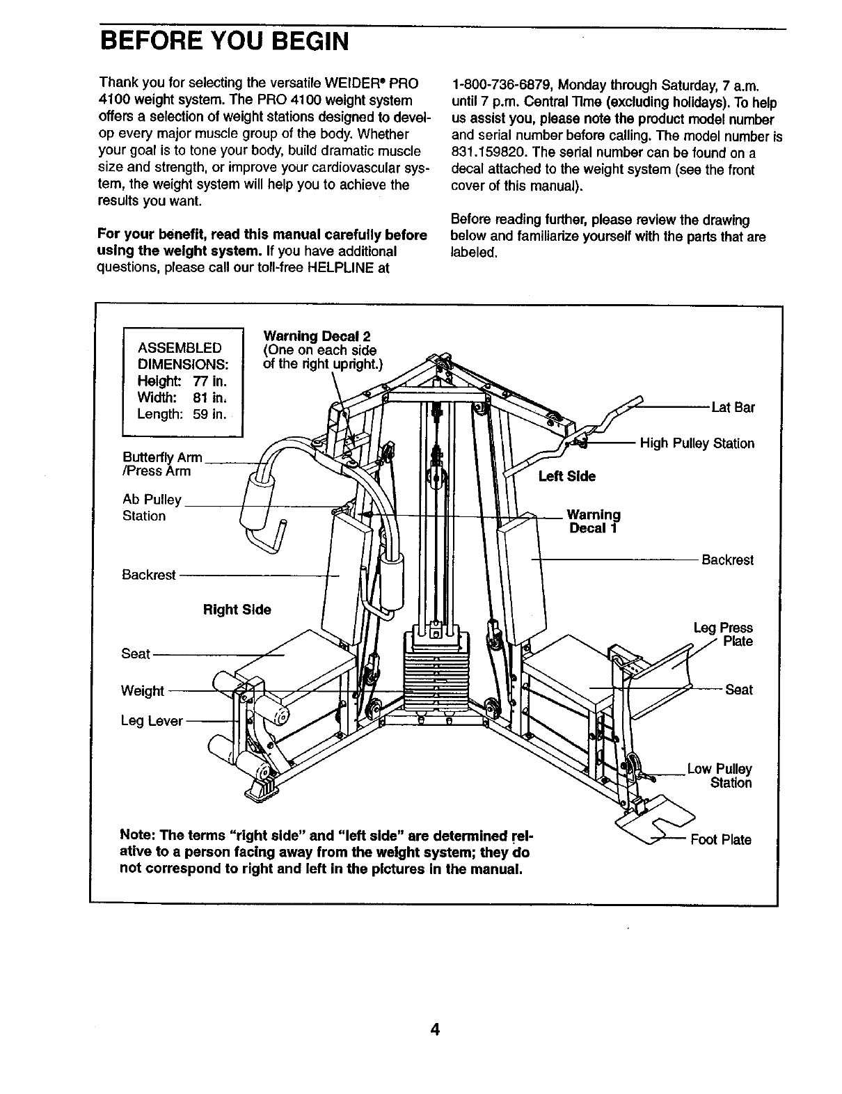
Before reading further, please review the drawing
below and familiadze yourself with the parts that are
labeled.
ASSEMBLED
DIMENSIONS:
Height: 77 in.
Width: 81 in,
Length: 59 in.
Butterfly
/Press Arm
Ab Pulley
Station
Backrest
Warning Decal 2
(One on each side
of the right updght.)
Left Side
I_atBar
gh Pulley Station
ig
Decal 1
Backrest
Seat
Right Side
Leg Press
Plate
Weight
Leg
__ Low Pulley
Station
Note: The terms "right side" and "left side" are determined I'el-
ative to a person facing away from the weight system; they do
not correspond to right and left in the pictures in the manual.
Foot Plate
4
ASSEMBLY
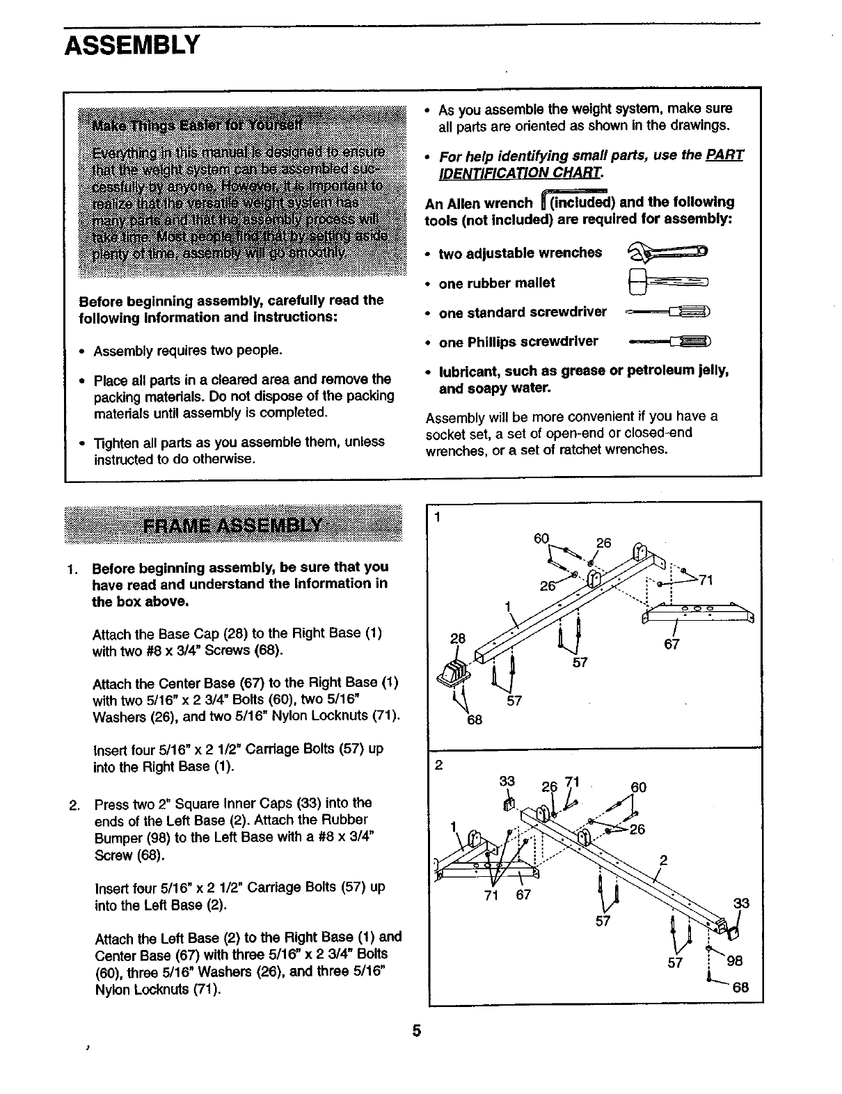
•As you assemble the weight system, make sure
all parts are odented as shown in the drawings.
Before beginning assembly, carefully read the
following information and instructions:
•Assembly requires two people.
• Place all parts in acleared area and remove the
packing materials. Do not dispose of the packing
materials until assembly is completed.
• 13ghten all parts as you assemble them, unless
instructedto do otherwise.
•For help identifying small pads, use the PART
ID I CA ON C T.
An Allen wrench _) and the following
tools (not included) are required for assembly:
•two adjustable wrenches _:_
•one rubber mallet
•one standard screwdriver
•one Phillips screwdriver
•lubricant, such as grease or petroleum jelly,
and soapy water.
Assembly will be more convenient if you have a
socket set, a set of open-end or closed-end
wrenches, or a set of ratchet wrenches.
1. Before beginning assembly, be sure that you
have read and understand the information in
the box above.
Attach the Base Cap (28) to the Right Base (1)
with two #8 x 3/4" Screws (68).
Attach the Center Base (67) to the Right Base (1)
with two 5/16" x 2 3/4" Bolts (60), two 5116"
Washers (26), and two 5/16" Nylon Locknuts (71).
insert four 5/16" x 2 1/2" Carriage Bolts (57) up
into the Right Base (1).
,Press two 2" Square Inner Caps (33) into the
ends of the Left Base (2). Attach the Rubber
Bumper (98) to the Left Base with a #8 x 3/4"
Screw (68).
Insert four 5/16" x 2 1/2" Carriage Bolts (57) up
into the Left Base (2).
Attach the Left Base (2) to the Right Base (1) and
Center Base (67) with three 5/16" x 2 3/4" Bolts
(60), three 5/16" Washers (26), and three 5/16"
Nylon Locknuts (71).
2
60 26
57
68
33
71 67
57
6O
2
57
33
5
t
3.
4.
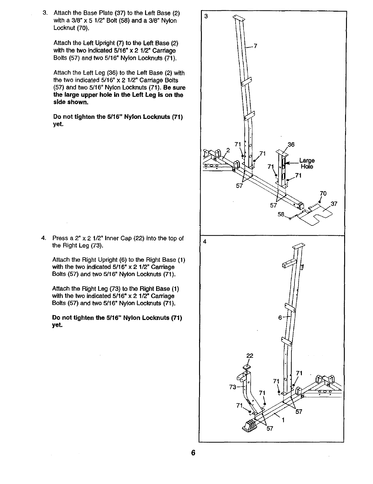
Attach the Base Plate (37) to the Left Base (2)
with a 3/8" x 5 1/2" Bolt (58) and a 3/8" Nylon
Locknut (70).
Attach the Left Upright (7) to the Left Base (2)
with the two indicated 5/16" x 2 1/2" Carriage
Bolts (57) and two 5/16" Nylon Locknuts (71).
Attach the Left Leg (36) to the Left Base (2) with
the two indicated 5/16" x 2 1/2" Carriage Bolts
(57) and two 5/16" Nylon Locknuts (71). Be sure
the large upper hole in the Left Leg is on the
side shown.
Do not tighten the 5/16" Nylon Locknuts (71)
yet.
Press a 2" x 2 1/2" Inner Cap (22) into the top of
the Right Leg (73).
Attach the Right Upright (6) to the Right Base (1)
with the two indicated 5/16" x 2 1/2" Carriage
Bolts (57) and two 5/16" Nylon Locknuts (71).
Attach the Right Leg (73) to the Right Base (1)
with the two indicated 5/16" x 21!2" Carriage
Bolts (57) and two 5/16" Nylon Lock,nuts (71).
Do not tighten the 5/16" Nylon Locknuts (71)
yet.
3
4
71 36
57
22
71
71
71
57
1
57
7O
6
5.
6+
7°
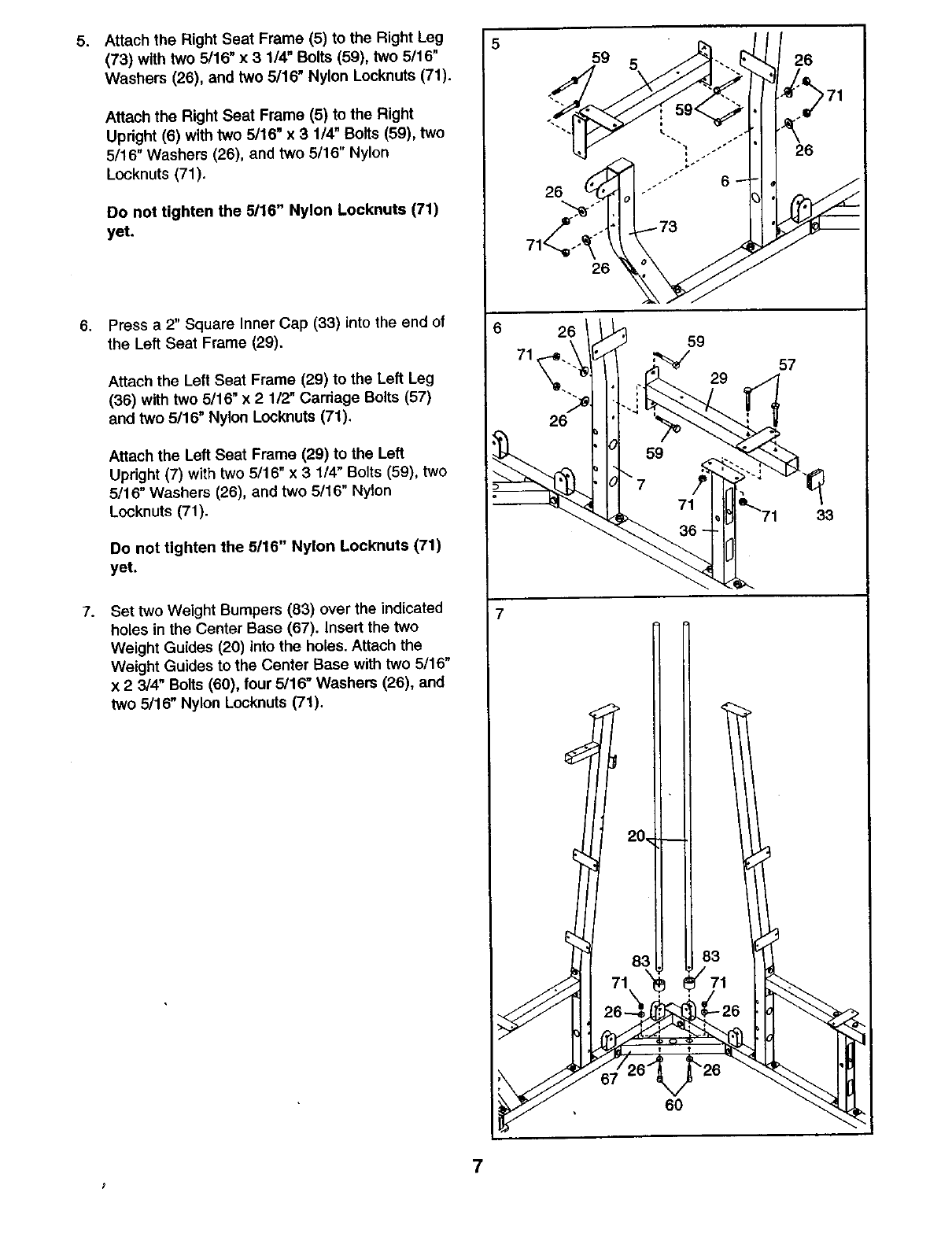
Attach the Right Seat Frame (5) to the Right Leg
(73) with two 5/16" x 3 1/4" Bolts (59), two 5/16"
Washers (26), and two 5/16" Nylon Locknuts (71).
Attach the Right Seat Frame (5) to the Right
Upright (6) with two 5/16" x3 1/4" Bolts (59), two
5/16" Washers (26), and two 5/16" Nylon
Locknuts (71).
Do not tighten the 5116" Nylon Locknuts (71)
yet.
Press a 2" Square Inner Cap (33) into the end of
the Left Seat Frame (29)°
Attach the Left Seat Frame (29) to the Left Leg
(36) with two 5/16" x 21/2" Carriage Bolts (57)
and two 5/16" Nylon Locknuts (71).
Attach the Left Seat Frame (29) to the Left
Updght (7) with two 5/16" x 3 1/4" Bolts (59), two
5/16" Washers (26), and two 5/16" Nylon
Locknuts (71).
Do not tighten the 5/16" Nylon Locknuts (71)
yet.
Set two Weight Bumpers (83) over the indicated
holes in the Center Base (67). Insert the two
Weight Guides (20) into the holes. Attach the
Weight Guides to the Center Base with two 5/16"
x 2 3/4" Bolts (60), four 5/16" Washers (26), and
two 5/16" Nylon Locknuts (71).
5
6
59
26
26
26
5
59
29
6O
26
26
57
33
7
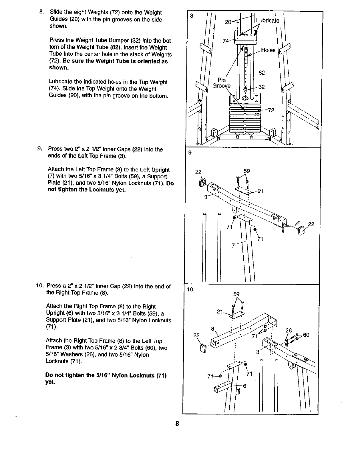
.Slide the eight Weights (72) onto the Weight
Guides (20) with the pin grooves on the side
shown.
Press the Weight Tube Bumper (32) into the bot-
tom of the Weight Tube (82). Insert the Weight
Tube into the center hole in the stack of Weights
(72). Be sure the Weight Tube is oriented as
shown.
Lubricate the indicated holes in the Top Weight
(74). Slide the Top Weight onto the Weight
Guides (20), with the pin groove on the bottom.
.Press two 2" x 2 112" inner Caps (22) into the
ends of the Left Top Frame (3).
Attach the Left Top Frame (3) to the Left Upright
(7) with two 5/16" x31/4" Bolts (59), a Support
Plate (21), and two 5/16" Nylon Looknuts (71). Do
not tighten the Locknuts yet.
10. Press a 2" x21/2" Inner Cap (22) into the end of
the Right Top Frame (8).
Attach the Right Top Frame (8) to the Right
Upright (6) with two 5/16" x 3 1/4" Bolts (59), a
Support Plate (21), and two 5/16" Nylon Locknuts
(71).
Attach the Right Top Frame (8) to the Left Top
Frame (3) with two 5/16" x 2 3/4" Bolts (60), two
5/16" Washers (26), and two 5/16" Nylon
Looknuts (71).
Do not tighten the 5/16" Nylon Locknuts (71)
yet.
9
22
10
22
8
59
59
L L
Lubricate
16 _71
26
_7 60
8
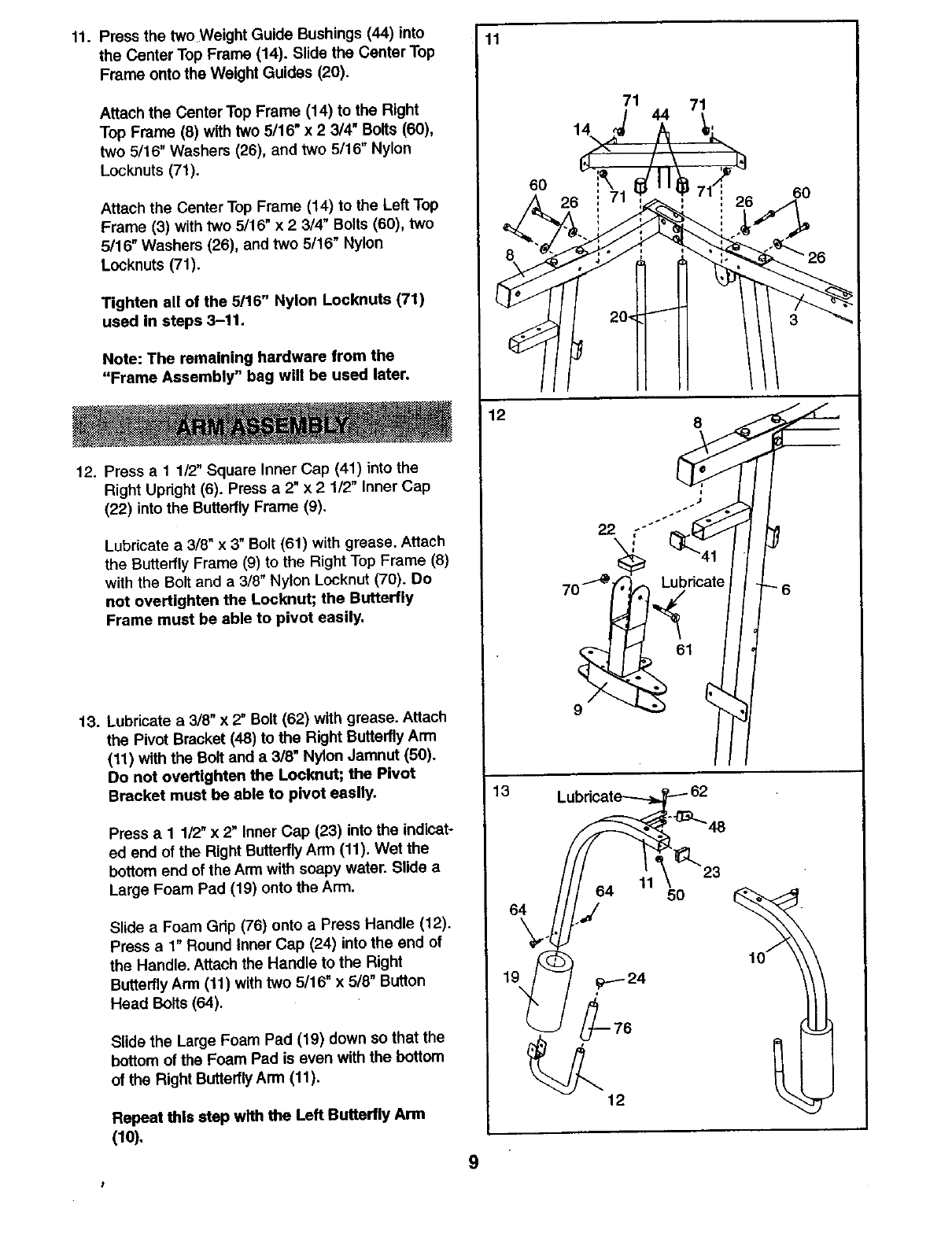
11. Press the two Weight Guide Bushings (44) into
the Center Top Frame (14), Slide the Center Top
Frame onto the Weight Guides (20).
Attach the Center Top Frame (14) to the Right
Top Frame (8) with two 5116"x2 3/4" Bolts (60),
two 5/16" Washers (26), and two 5/16" Nylon
Locknuts (71).
Attach the Center Top Frame (14) to the Left Top
Frame (3) with two 5/16" x 23/4" Bolts (60), two
5/16" Washers (26), and two 5/16" Nylon
Locknuts (71).
Tighten all of the 5/16" Nylon Locknuts (71)
used In steps 3-11.
Note: The remaining hardware from the
"Frame Assembly" bag will be used later.
12. Press a 11/2" Square Inner Cap (41) into the
Right Updght (6). Press a 2" x 2 1/2" Inner Cap
(22) into the Butterfly Frame (9).
Lubricate a3/8" x 3" Bolt (61) with grease, Attach
the Butterfly Frame (9) to the Right Top Frame (8)
with the Boit and a 3/8" Nylon Locknut (70). Do
not overUghten the Locknut; the Butterfly
Frame must be able to pivot easily.
13. Lubricate a 3/8" x2" Bolt (62) with grease. Attach
the Pivot Bracket (48) to the Right Buttedly Arm
(11) with the Bolt and a 3/8" Nylon Jamnut (50).
Do not overtighten the Locknut; the Pivot
Bracket must be able to pivot easily.
Press a I 1/2" x 2" Inner Cap (23) into the indicat-
ed end of the Right Butterfly Arm (11). Wet the
bottom end of the Arm with soapy water. Slide a
Large Foam Pad (19) onto the Arm.
Slide a Foam Gdp (76) onto a Press Handle (12).
Press a 1" Round Inner Cap (24) into the end of
the Handle. Attach the Handle to the Right
Butterfly Arm (11) with two 5/16" x 5/8" Button
Head Bolts (64).
Slide the Large Foam Pad (19) down so that the
bottom of the Foam Pad is even with the bottom
of the Right ButterflyArm (11).
Repeat this step with the Left Butterfly Arm
(10),
11
13
60
64
71 71
44
14
8
11 5o
60
9
t
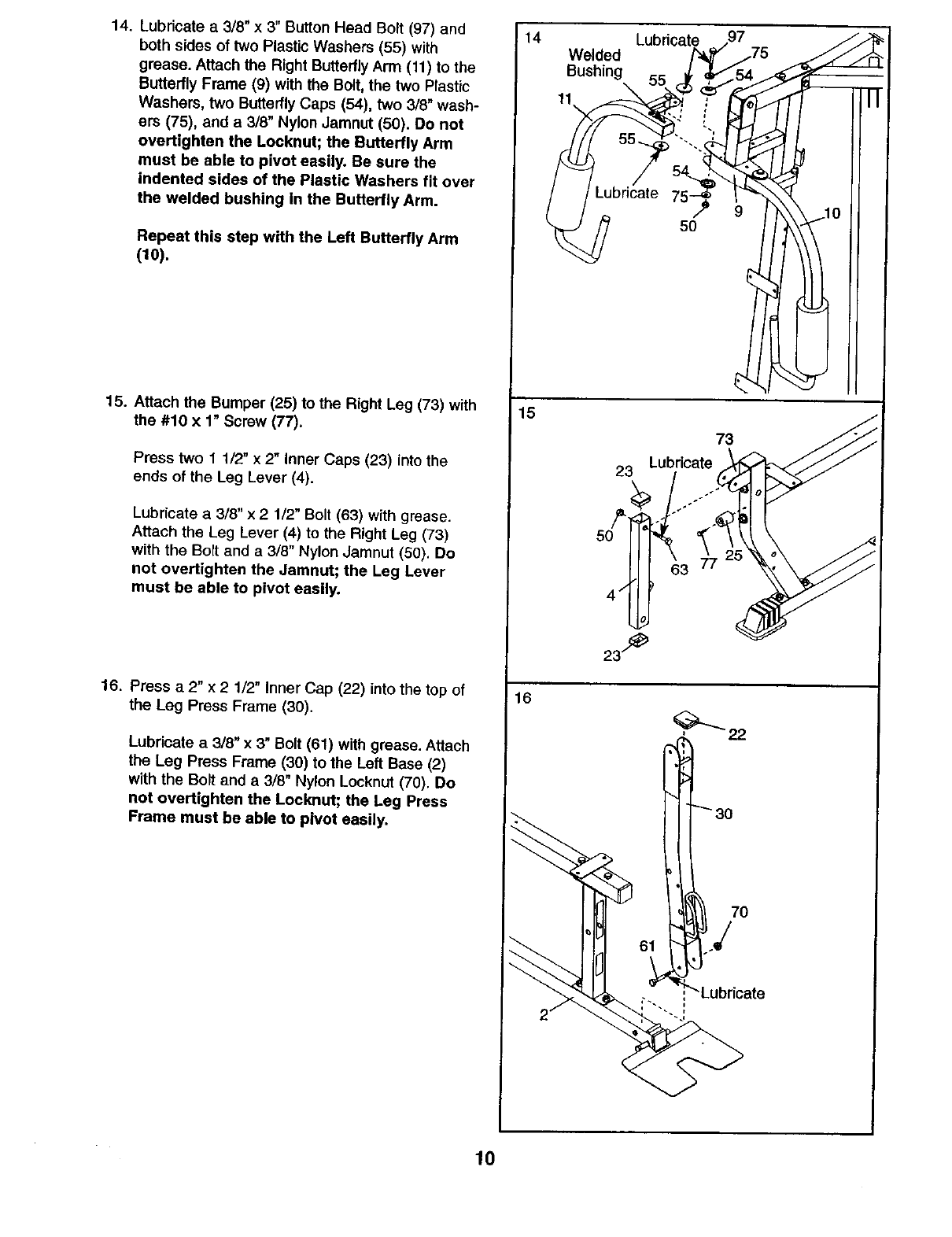
14. Lubricate a 3/8"x 3" Button Head Bolt (97) and
both sides of two Plastic Washers (55) with
grease. Attach the Right Butterfly Arm (11) to the
Butterfly Frame (9) with the Bolt, the two Plastic
Washers, two Butterfly Caps (54), two 3/8" wash-
ers (75), and a 3/8" Nylon Jamnut (50). Do not
overt|ghten the Locknut; the Butterfly Arm
must be able to pivot easily. Be sure the
indented sides of the Plastic Washers fit over
the welded bushing In the Butterfly Arm.
Repeat this step with the Left Butterfly Arm
(10).
15. Attach the Bumper (25) to the Right Leg (73) with
the #10 x 1" Screw (77).
Press two 11/2" x 2" Inner Caps (23) into the
ends of the Leg Lever (4).
Lubricate a 3/8" x 21/2" Bolt (63) with grease.
Attach the Leg Lever (4) to the Right Leg (73)
with the Bolt and a 3/8" Nylon Jamnut (50). Do
not overtighten the Jamnut; the Leg Lever
must be able to pivot easily.
16. Press a 2" x 2112" Inner Cap (22) into the top of
the Leg Press Frame (30).
Lubricate a3/8" x 3" Bolt (61) with grease. Attach
the Leg Press Frame (30) to the Left Base (2)
with the Bolt and a 3/8" Nylon Locknut (70). Do
not overtighten the Locknut; the Leg Press
Frame must be able to pivot easily.
14
15
16
Welded Lubricate _7
5O
73
Lubricate
520!i "'_61 "°"
23/_
70
61
Lubricate
10
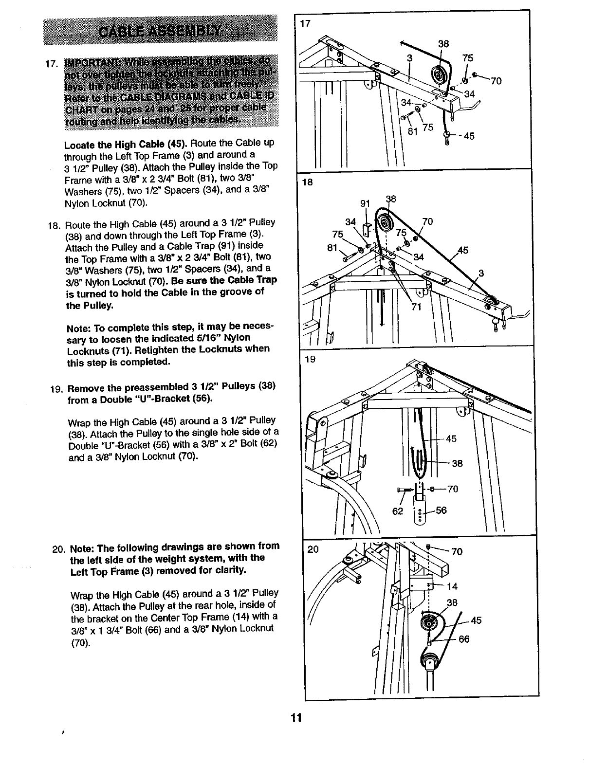
17.
Locate the High Cable (45). Route the Cable up
through the Left Top Frame (3) and around a
3 1/2" Pulley (38), Attach the Pulley inside the Top
Frame with a 3/8" x 2 3/4" Bolt (81), two 3/6"
Washers (75), two 1/2" Spacers (34), and a 3/8"
Nylon Locknut (70).
18. Route the High Cable (45) around a 3 1/2" Pulley
(38) and down through the Left Top Frame (3).
Attach the Pulley and a Cable Trap (91) inside
the Top Frame with a 3/8" x 2 3/4" Bolt (81), two
3/8" Washers (75), two 1/2" Spacers (34), and a
3/8" Nylon Locknut (70). Be sure the Cable Trap
is turned to hold the Cable in the groove of
the Pulley.
Note: To complete this step, it may be neces-
saw to loosen the indicated 5/16" Nylon
Locknuts (71). Retighten the Locknuts when
this step Is completed.
19. Remove the preassembled 3 1/2" Pulleys (38)
from a Double "U"-Bracket (56).
Wrap the High Cable (45) around a 3 1/2" Pulley
(38). Attach the Pulley to the single hole side of a
Double "U"-Bracket (56) with a 3/8" x2" Bolt (62)
and a 3/8" Nylon Locknut (70).
20. Note: The following drawings are shown from
the left side of the weight system, wfth the
Left Top Frame (3) removed for clarity.
Wrap the High Cable (45) around a 3 112"Pulley
(38). Attach the Pulley at the rear hole, inside of
the bracket on the Center Top Frame (14) with a
3/8" x 1 3/4" Bolt (66) and a3/8" Nylon Locknut
(70).
75
45
18
91
34
75 \
81,
38
70
19
62
38
11
I
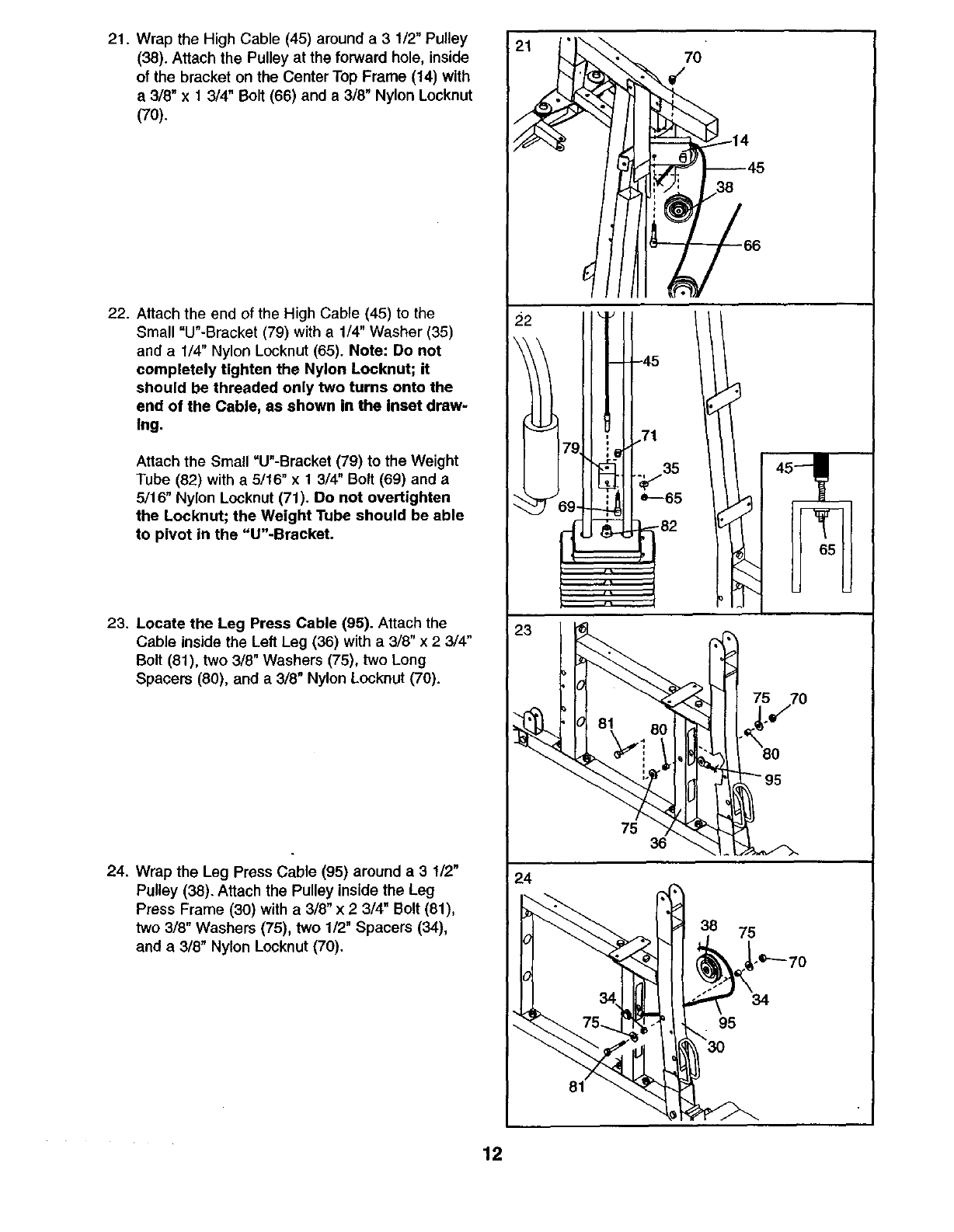
21. Wrap the High Cable (45) around a 3 1/2" Pulley
(38). Attach the Pulley at the forward hole, inside
of the bracket on the Center Top Frame (14) with
a 3/8" x 1 3/4" Bolt (66) and a 3/8" Nylon Locknut
(70).
22. Attach the end of the High Cable (45) to the
Small "U'-Bracket (79) with a 1/4" Washer (35)
and a1/4" Nylon Locknut (65). Note: De net
completely tighten the Nylon Locknut; it
should be threaded only two turns onto the
end of the Cable, as shown in the inset draw-
Ing.
Attach the Small "U"-Bracket (79) to the Weight
Tube (82) with a 5/16" x 1 3/4" Bolt (69) and a
5/16" Nylon Locknut (71). Do not overtighten
the Locknut; the Weight Tube should be able
to pivot in the "U"-Bracket.
23. Locate the Leg Press Cable (95). Attach the
Cable inside the Left Leg (36) with a 3/8" x 2 3/4"
Bolt (81), two 3/8" Washers (75), two Long
Spacers (80), and a 3/8" Nylon Locknut (70).
24. Wrap the Leg Press Cable (95) around a 3 1/2"
Pulley (38). Attach the Pulley inside the Leg
Press Frame (30) with a3/8" x 23/4" Bolt (81),
two 3/8" Washers (75), two 1/2" Spacers (34),
and a 3/8" Nylon Locknut (70).
22 i _''
1-°
'1
_ ,71
79, i
69- e'-'65
I1
.... ii
°°
I'
45--- I
24
° _.
; 38 75
,, --. _t_._'e'-'- 70
Ih
II 30
II
65 ,
I
12
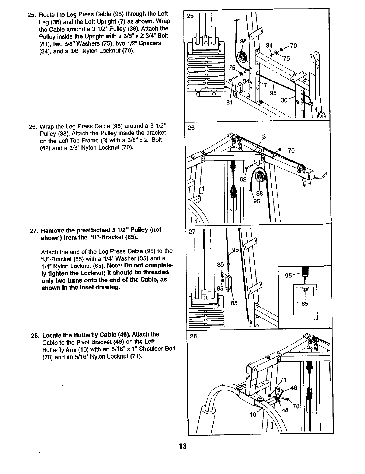
25. Route the Leg Press Cable (95) through the Left
Leg (36) and the Left Upright (7) as shown. Wrap
the Cable around a 3 1/2" Pulley (38). Attach the
Pulley inside the Upright with a 318"x 2 3/4" Bolt
(81), two 3/8" Washers (75), two 1/2" Spacers
(34), and a 3/8" Nylon Locknut (70).
26. Wrap the Leg Press Cable (95) around a31/2"
Pulley (38). Attach the Pulley inside the bracket
on the Left Top Frame (3) with a 3/8" x 2" Bolt
(62) and a 3/8" Nylon Locknut (70).
27. Remove the preattached 3 1/2" Pulley (not
shown) from the "U"-Bracket (85).
Attach the end of the Leg Press Cable (95) to the
=U"-Bracket (85) with a 1/4" Washer (35) and a
1/4" Nylon Locknut (65). Note: Do not complete-
ly tighten the Locknut; it should be threaded
only two turns onto the end of the Cable, as
shown in the inset drawing.
28. Locate the Butterfly Cable (46). Attach the
Cable to the Pivot Bracket (48) on the Left
ButterflyArm (10) with an 5/16" x 1" Shoulder Bolt
(78) and an 5/16" Nylon Locknut (71).
81
26
28
10
13
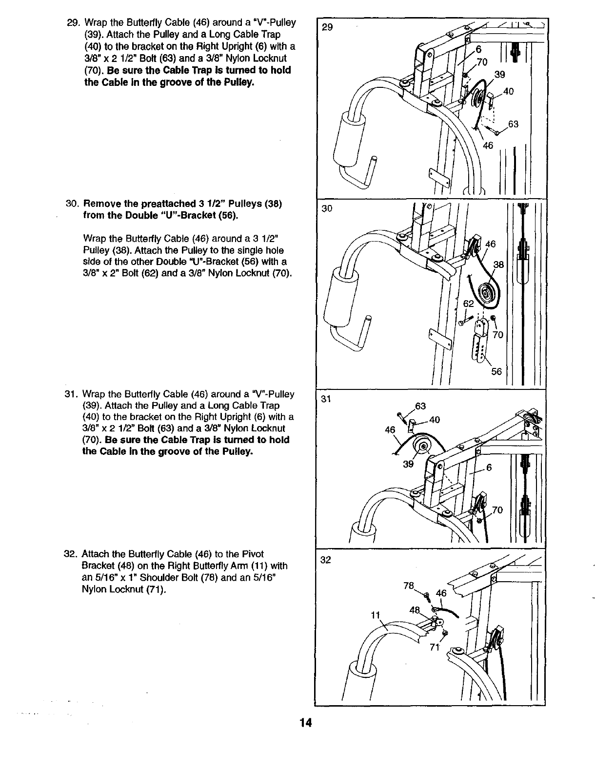
29. Wrap the Butterfly Cable (46) around a =V"-Pulley
(39). Attach the Pulley and a Long Cable Trap
(40) to the bracket on the Right Upright (6) with a
318" x 2 1/2" Bolt (63) and a 3/8" Nylon Locknut
(70). Be sure the Cable Trap Is turned to hold
the Cable In the groove of the Pulley.
30. Remove the preattached 3 1/2" Pulleys (38)
from the Double "U"-Bracket (56).
Wrap the Butterfly Cable (46) around a 3 1/2"
Pulley (38). Attach the Pulley to the single hole
side of the other Double "U"-Bracket (56) with a
3/8" x 2" Bolt (62) and a 3/8" Nylon Locknut (70).
31. Wrap the Butterfly Cable (46) around a "V"-Pulley
(39). Attach the Pulley and a Long Cable Trap
(40) to the bracket on the Right Upright (6) with a
3/8" x 2 1/2" Bolt (63) and a 3/8" Nylon Locknut
(70). Be sure the Cable Trap is turned to hold
the Cable in the groove of the Pulley.
32. Attach the Butterfly Cable (46) to the Pivot
Bracket (48) on the Right ButterflyArm (11) with
an 5/16" x 1" Shoulder Bolt (78) and an 5/16"
Nylon Locknut (71).
30
/// 56
31
39
32
11
14
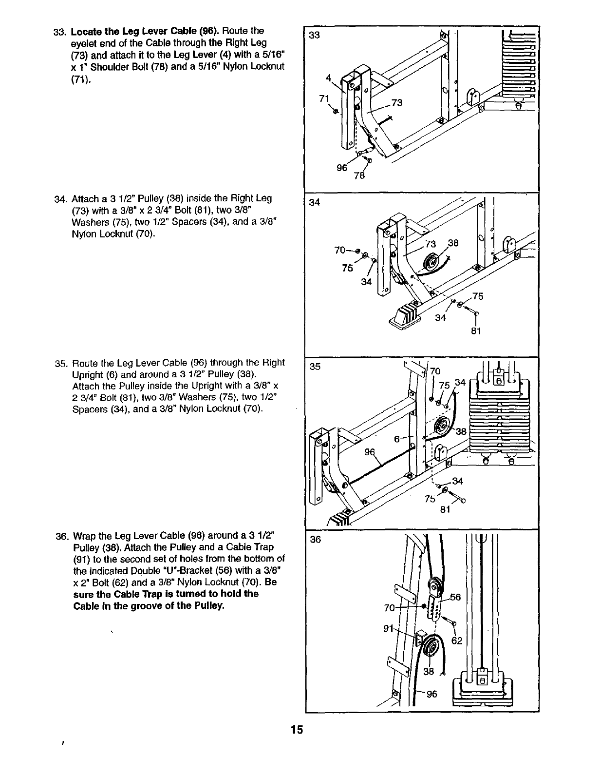
33. Locate the Leg Lever Cable (96). Route the
eyelet end of the Cable through the Right Leg
(73) and attach it to the Leg Lever (4) with a 5/16"
x1" Shoulder Bolt (78) and a 5116" Nylon Locknut
(71).
34. Attach a 31/2" Pulley (36) inside the Right Leg
(73) with a 3/8" x 2 3/4" Bolt (81), two 3/8"
Washers (75), two 1/2" Spacers (34), and a 3/8"
Nylon Locknut (70).
35. Route the Leg Lever Cable (96) through the Right
Upright (6) and around a 3 1/2" Pulley (38).
Attach the Pulley inside the Upright with a 3/8" x
2 3/4" Bolt (81), two 3/8" Washers (75), two 1/2"
Spacers (34), and a 3/8" Nylon Locknut (70).
36. Wrap the Leg Lever Cable (96) around a 3 1/2"
Pulley (38). Attach the Pulley and a Cable Trap
(91) to the second set of holes from the bottom of
the indicated Double "U"-Bracket (56) with a 3/8"
x 2" Bolt (62) and a 3/8" Nylon Locknut (70). Be
sure the Cable Trap is turned to hold the
Cable in the groove of the Pulley.
33
34
35
36
96 78
34
34
8t
81
15
J
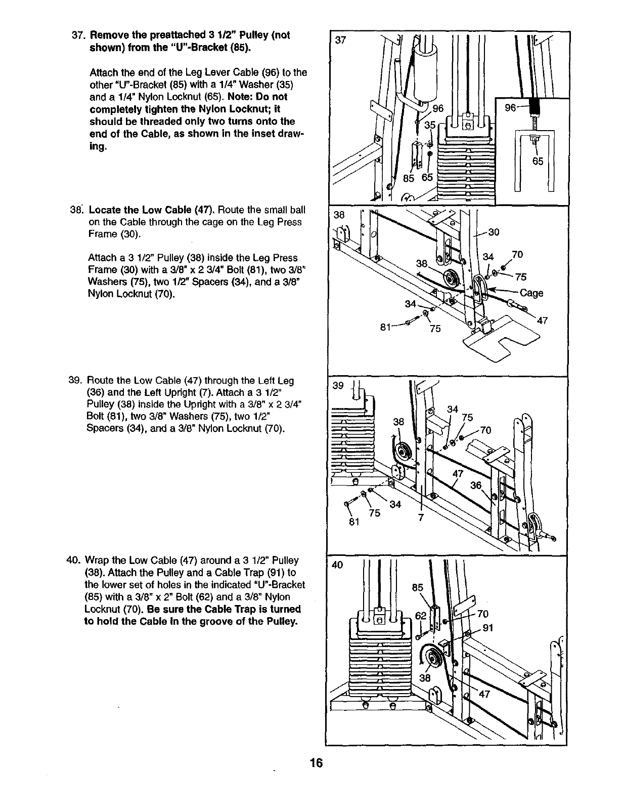
37. Remove the preettached 3 112" Pulley (not
shown) from the "U"-Bracket (85).
Attach the end of the Leg Lever Cable (96) to the
other =U"-Bracket (85) with a 1/4" Washer (35)
and a1/4" Nylon Locknut (65). Note: Do not
completely tighten the Nylon Locknut; it
should be threaded only two turns onto the
end of the Cable, as shown in the inset draw-
ing.
38_ Locate the Low Cable (47), Route the small ball
on the Cable through the cage on the Leg Press
Frame (30).
Attach a 3 1/2" Pulley (38) inside the Leg Press
Frame (30) with a3/8" x 2 3/4" Bolt (81), two 3/8"
Washers (75), two 1/2" Spacers (34), and a 3/8"
Nylon Locknut (70).
39. Route the Low Cable (47) through the Left Leg
(36) and the Left Upright (7). Attach a 3 1/2"
Pulley (38) inside the Upright with a 3/8" x 2 3/4"
Bolt (81), two 3/8" Washers (75), two 1/2"
Spacers (34), and a 3/8" Nylon Locknut (70).
40. Wrap the Low Cable (47) around a 3 1/2" Pulley
(38). Attach the Pulley and aCable Trap (91) to
the lower set of holes in the indicated =U'-Bracket
(85) with a 318" x 2" Bolt (62) and a 3/8" Nylon
Locknut (70). Be sure the Cable Trap is turned
to hold the Cable In the groove of the Pulley.
37
7O
81 75
81 7
34
16
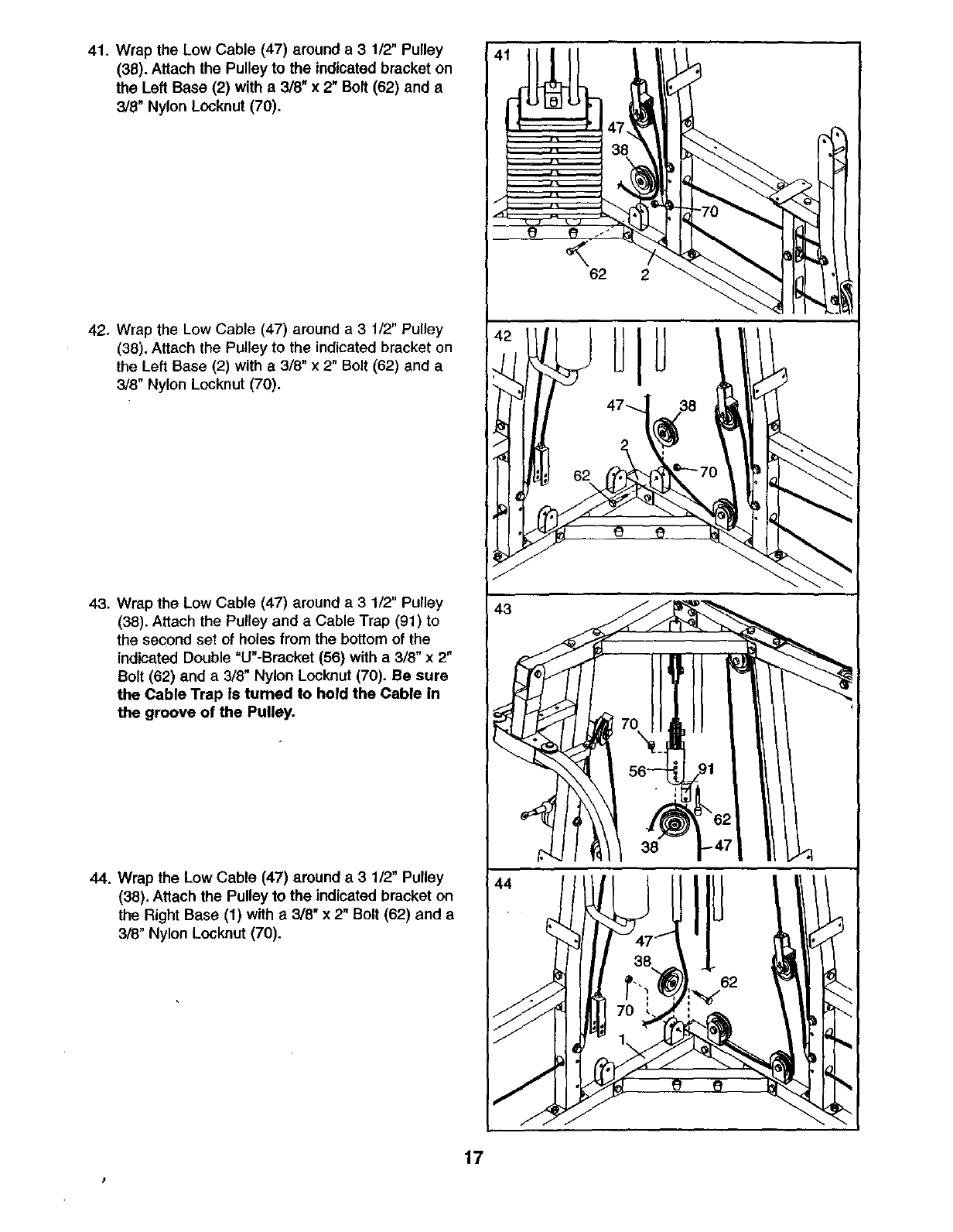
41. Wrap the Low Cable (47) around a31/2" Pulley
(38). Attach the Pulley to the indicated bracket on
the Left Base (2) with a 3/8" x 2" Bolt (62) and a
3/8" Nylon Locknut (70).
42. Wrap the Low Cable (47) around a 3 1/2" Pulley
(38). Attach the Pulley to the indicated bracket on
the Left Base (2) with a 3/8" x 2" Bolt (62) and a
3/8" Nylon Lecknut (70).
43. Wrap the Low Cable (47) around a 3 1/2" Pulley
(38). Attach the Pulley and a Cable Trap (91) to
the second set of holes from the bottom of the
indicated Double =U"-Bracket (56) with a 3/8" x 2"
Bolt (62) and a 3/8" Nylon Locknut (70). Be sure
the Cable Trap is turned to hold the Cable in
the groove of the Pulley.
44. Wrap the Low Cable (47) around a31/2" Pulley
(38). Attach the Pulley to the indicated bracket on
the Right Base (1) with a 3/8" x 2" Bolt (62) and a
3/8" Nylon Locknut (70).
56- ,:1 I till
rI ;.3
¢ ql
17
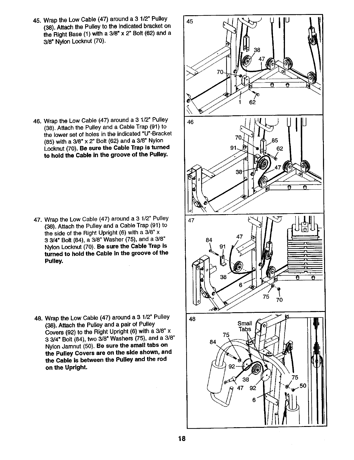
45. Wrap the Low Cable (47) around a 3 1/2" Pulley
(38). Attach the Pulley to the indicated bracket on
the Right Base (1) with a 3/8" x 2" Bolt (62) and a
3/8" Nylon Locknut (70).
46. Wrap the Low Cable (47) around a 3 1/2" Pulley
(38). Attach the Pulley and a Cable Trap (91) to
the lower set of holes in the indicated "U"-Bracket
(85) with a 3/8" x 2" Bolt (62) and a 3/8" Nylon
L0cknut (70). Be sure the Cable Trap is turned
to hold the Cable in the groove of the Pulley.
47. Wrap the Low Cable (47) around a 3 1/2" Pulley
(38). Attach the Pulley and a Cable Trap (91) to
the side of the Right Upright (6) with a 3/8" x
3 3/4" Bolt (84), a 3/8" Washer (75), and a 3/8"
Nylon Locknut (70). Be sure the Cable Trap is
turned to hold the Cable in the groove of the
Pulley.
48. Wrap the Low Cable (47) around a 31/2" Pulley
(38). Attach the Pulley and a pair of Pulley
Covers (92) to the Right Upright (6) with a3/8" x
33/4" Bolt (84), two 3/8" Washers (75), and a 3/8"
Nylon Jamnut (50). Be sure the small tabs on
the Pulley Covers are on the side shown, and
the Cable is between the Pulley and the rod
on the Upright.
45 l iu
46
47
84 47
48 Small
/ -3c)
47 92
8 1
75
_-_150
18
::_ ::_:_s_ .'_" '_ "_" ""_ "' """ "_ -•_ _'""_- ""_• _ _ _- • "_'1¸ "_@
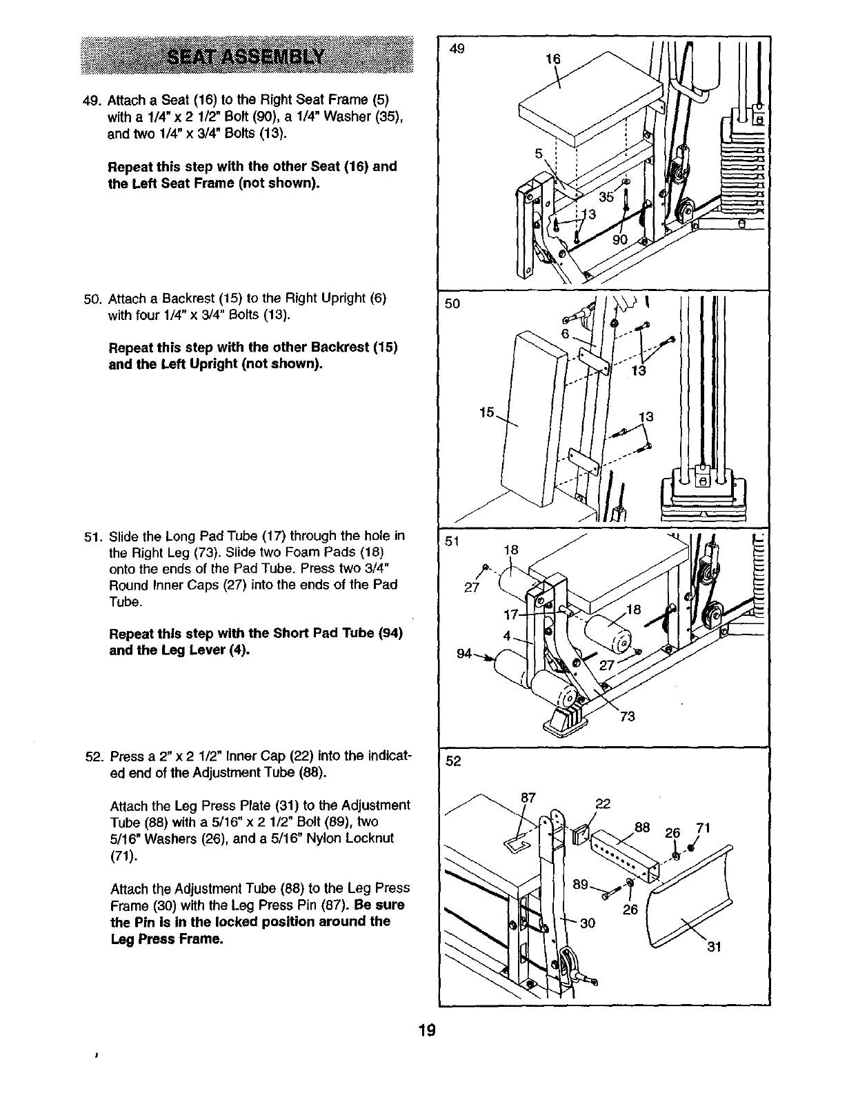
49. Attach a Seat (16) to the Right Seat Frame (5)
with a 1/4" x 2 1/2" Bolt (90), a1/4" Washer (35),
and two 1/4" x 3/4" Bolts (13).
Repeat this step with the other Seat (16) and
the Left Seat Frame (not shown).
50. Attach a Backrest (15) to the Right Upright (6)
with four 1/4" x 3/4" Bolts (13).
Repeat this step with the other Backrest (15)
and the Left Upright (not shown).
51. Slide the Long Pad Tube (17) through the hole in
the Right Leg (73). Slide two Foam Pads (18)
onto the ends of the Pad Tube. Press two 3/4"
Round Inner Caps (27) into the ends of the Pad
Tube.
Repeat this step with the Short Pad Tube (94)
and the Leg Lever (4).
52. Press a 2" x21/2" Inner Cap (22) into the indicat-
ed end of the Adjustment Tube (88).
Attach the Leg Press Plate (31) to the Adjustment
Tube (88) with a 5/16" x 2 1/2" Bolt (89), two
5/16" Washers (26), and a 5/16" Nylon Locknut
(71).
Attach the Adjustment Tube (88) to the Leg Press
Frame (30) with the Leg Press Pin (87). Be sure
the Pin is in the locked position around the
Leg Press Frame.
49
5O
15.
52
87
16
5
13
13
73
22
26
26 71
31
19
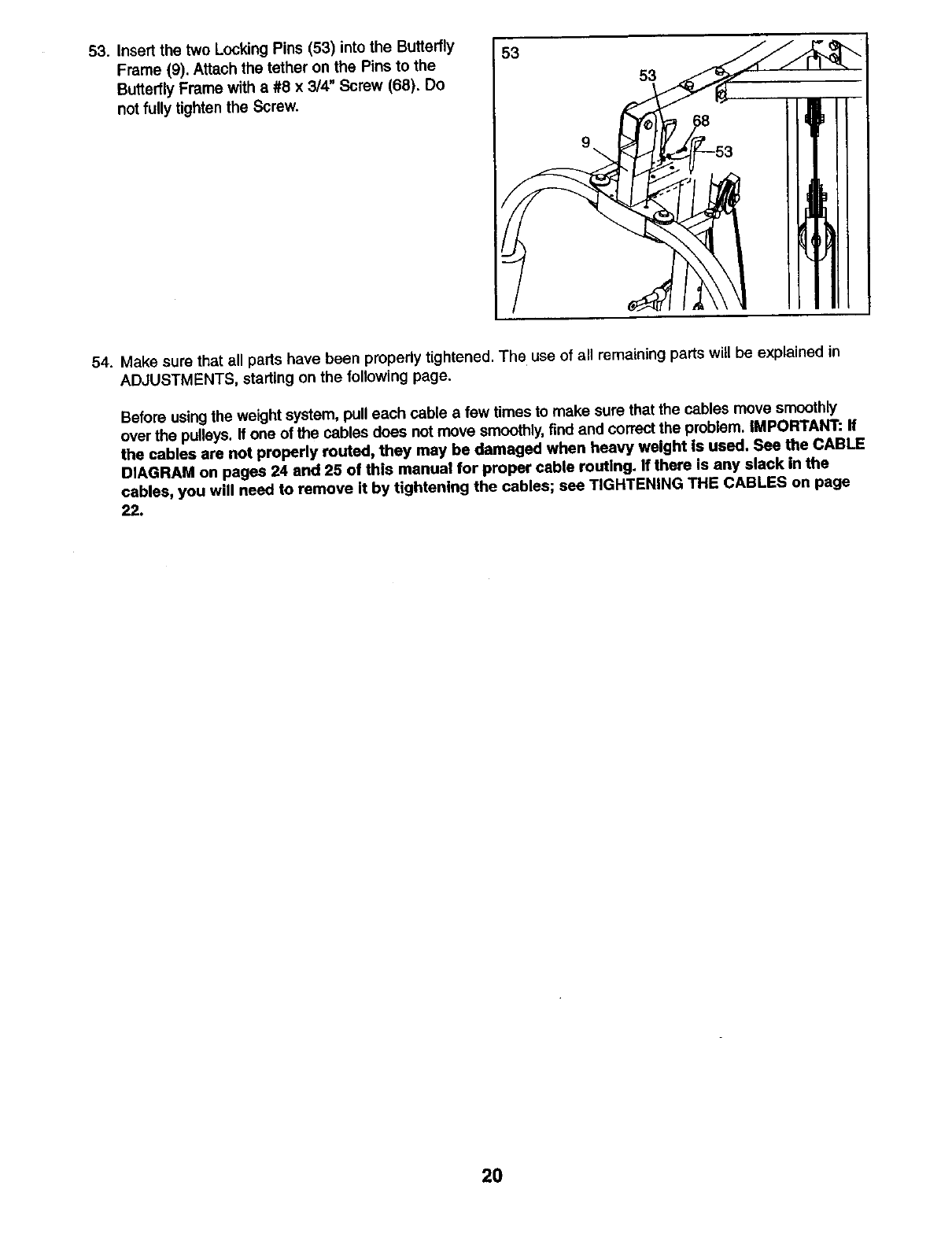
53. Insert the two Locking Pins (53) into the Butterfly
Frame (9). Attach the tether on the Pins to the
Butterfly Frame with a #8 x 3/4" Screw (68). Do
not fully tighten the Screw.
53
9
53
!
54. Make sure that all parts have been properly tightened. The use of all remaining parts will be explained in
ADJUSTMENTS, starting on the following page.
Before using the weight system, pull each cable a few times to make sure that the cables move smoothty
over the pulleys. If one of the cables does not move smoothly,find and correct the problem. IMPORTANT: ff
the cables are not properly routed, they may he damaged when heavy weight is used. See the CABLE
DIAGRAM on pages 24 and 25 of this manual for proper cable routing. If there is any slack in the
cables, you will need to remove it by tightening the cables; see TIGHTENING THE CABLES on page
22.
20
ADJUSTMENTS
This section explains how to adjust the weight system. See the EXERCISE GUIDELINES on page 26 for impor-
tant information about how to get the most benefit from your exercise program. Also, refer to the accompanying
exercise guide to see the correct form for each exemise.
Make sure all parts are properlytightened each time the weight system is used. Replace any worn parts immediate-
ly. The weight system can be cleaned with a damp cloth and a mild, non-abrasive detergent. Do not use solvents.
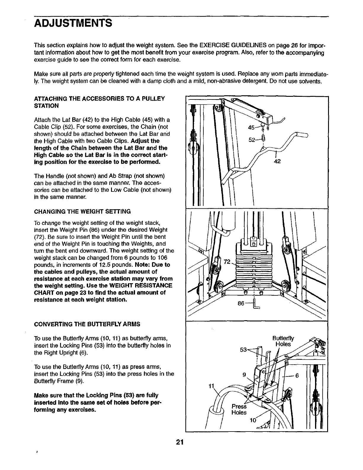
ATTACHING THE ACCESSORIES TO A PULLEY
STATION
Attach the Lat Bar (42) to the High Cable (45) with a
Cable Clip (52). For some exercises, the Chain (not
shown) should be attached between the Lat Bar and
the High Cable with two Cable Clips. Adjust the
length of the Chain between the I.at Bar and the
High Cable so the Lat Bar is in the correct start-
ing position for the exercise to be performed.
The Handle (not shown) and Ab Strap (not shown)
can be attached in the same manner. The acces-
sories can be attached to the Low Cable (not shown)
in the same manner.
42
CHANGING THE WEIGHT SETTING
To change the weight setting of the weight stack,
insert the Weight Pin (86) under the desired Weight
(72). Be sure to insert the Weight Pin until the bent
end of the Weight Pin is touching the Weights, and
tum the bent end downward. The weight setting of the
weight stack can be changed from 6 pounds to 106
pounds, in increments of 12.5 pounds. Note; Due to
the cables and pulleys, the actual amount of
resistance at each exercise station may vary from
the weight setting. Use the WEIGHT RESISTANCE
CHART on page 23 to find the actual amount of
resistance at each weight station.
CONVERTING THE BUTTERFLY ARMS
To use the Butterfly Arms (10, 11) as butterfly arms,
insert the Locking Pins (53) into the butterfly holes in
the Right Upright (6).
To use the Buttertly Arms (10, 11) as press arms,
insert the Locking Pins (53) into the press holes in the
Butterfly Frame (9).
Make sure that the Locking Pins (53) are fully
Inserted Into the same set of holes before pep
forming any exercises.
Butterfly
Holes
9
11
Holes
21
,t
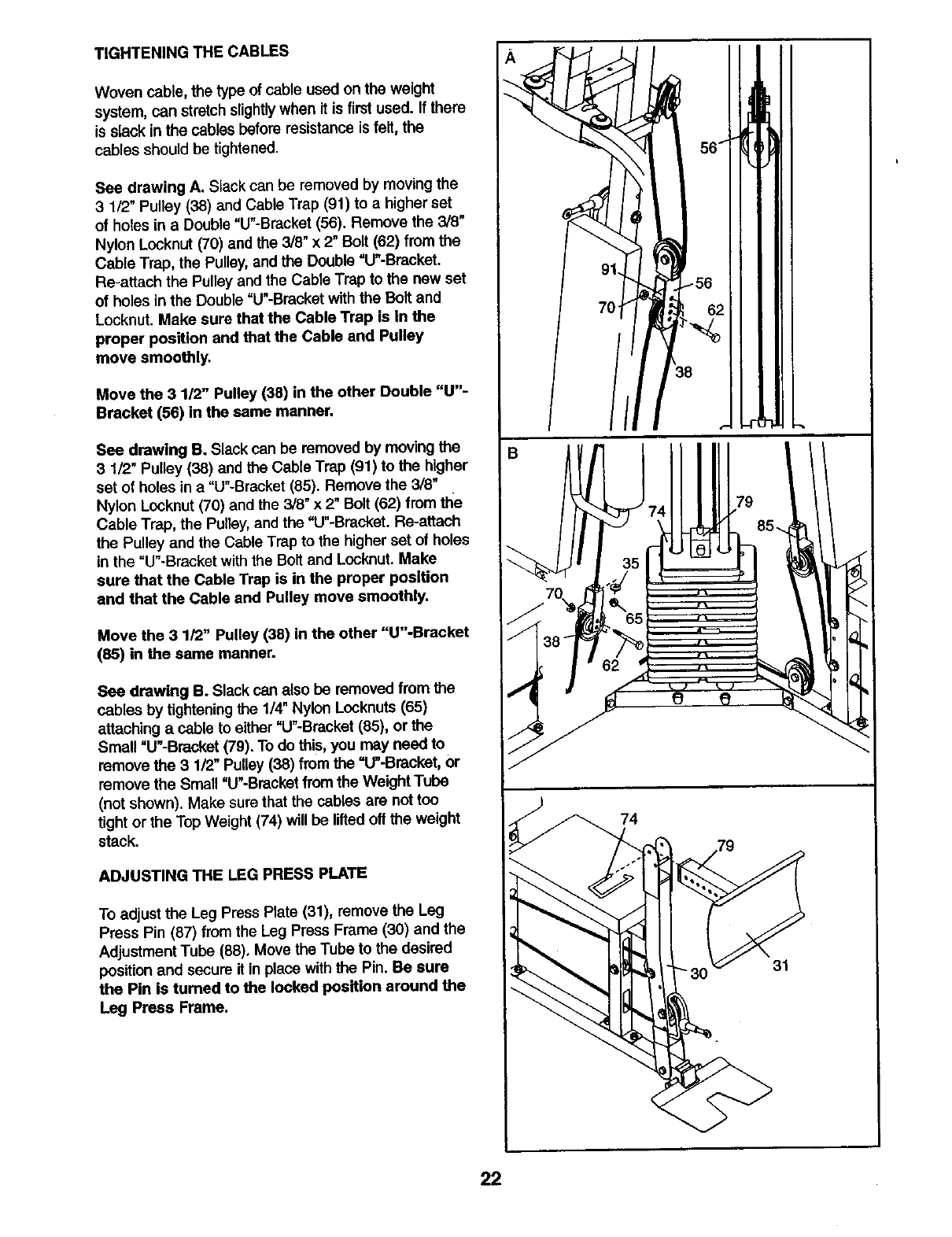
TIGHTENING THE CABLES
Woven cable, the type of cable used on the weight
system, can stretch slightlywhen it is firstused. If there
is slack in the cables before resistance is felt, the
cables should be tightened.
See drawing A. Slack can be removed by movingthe
3 1/2" Pulley (38) and Cable Trap (91) to a higher set
of holes in a Double "tY-Bracket (56). Remove the 3/6"
Nylon Locknut (70) and the 3/8" x 2" Bolt (62) from the
Cable Trap, the Pulley,and the Double "U"-Bracket.
Re-attach the Pulley and the Cable Trap to the new set
of holes in the Double "U"-Bracketwith the Bolt and
Locknut. Make sure that the Cable Trap is In the
proper position and that the Cable and Pulley
move smoothly.
Move the 3 1/2" Pulley (38) in the other Double "U"-
Bracket (56) in the same manner.
See drawing B. Slack can be removed by moving the
3 1/2" Pulley (38) and the Cable Trap (91) to the higher
set of holes in a "U"-Brecket (85). Remove the 3/8"
Nylon Locknut(70) and the 3/8" x 2" Bolt (62) from the
Cable Trap, the Pulley,and the =U"-Bracket. Re-attach
the Pulley and the Cable Trap to the higher set of holes
in the =U"-Bracket with the Bolt and Locknut. Make
sure that the Cable Trap is in the proper position
and that the Cable and Pulley move smoothly.
Move the 3 1/2" Pulley (38) in the other "U"-Bracket
(85) in the same manner.
See drawing B. Slack can also be removed from the
cables by tightening the 1/4" Nylon Locknuts(65)
attaching a cable to either "U"-Bracket (85), or the
Small "U"-Bracket (79). To do this, you may need to
remove the 3 1/2" Pulley (38) from the "U"-Bracket, or
remove the Small "U"-Bracket from the Weight Tube
(not shown). Make sure that the cables are not too
tight or the Top Weight (74) will be lifted off the weight
stack.
ADJUSTING THE LEG PRESS PLATE
To adjust the Leg Press Plate (31), remove the Leg
Press Pin (87) from the Leg Press Frame (30) and the
Adjustment Tube (88). Move the Tube to the desired
positionand secure it in place with the Pin. Be sure
the Pin is turned to the locked position around the
Leg Press Frame.
74
31
22
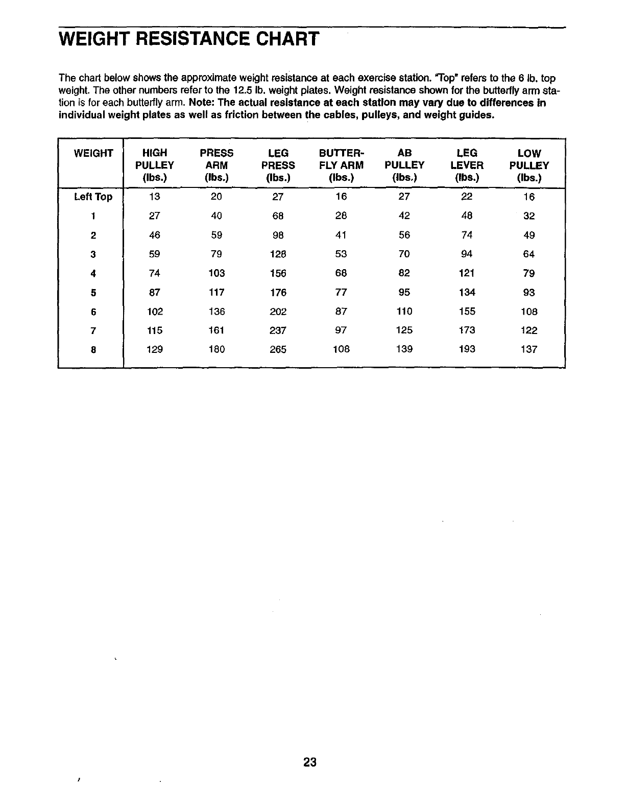
WEIGHT RESISTANCE CHART
The chart below shows the approximate weight resistance at each exercise station. "Top"refers to the 6Ib, top
weight. The other numbers refer to the 12.5 lb. weight plates. Weight resistance shown for the butterfly arm sta-
tion is for each butterfly arm. Note: The actual resistance at each station may vary due to differences In
individual weight plates as well as friction between the cables, pulleys, and weight guides.
WEIGHT PRESS LEG
ARM PRESS
(Ibs.) (Ibs.)
Left Top
1
2
3
4
5
6
7
8
HIGH BUTTER- AB LEG LOW
PULLEY FLYARM PULLEY LEVER PULLEY
(Ibs.) (Ibs.) (Ibs.) (Ibs.) (Iba.)
13 20 27 16 27 22 16
27 40 68 28 42 48 32
46 59 98 41 56 74 49
59 79 128 53 70 94 64
74 103 156 68 82 121 79
87 117 176 77 95 134 93
102 136 202 87 110 155 108
115 161 237 97 125 173 122
129 180 265 108 139 193 137
23
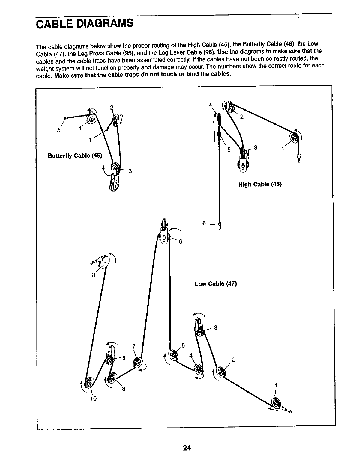
CABLE DIAGRAMS
The cable diagrams below show the proper muting of the High Cable (45), the ButterflyCable (46), the Low
Cable (47), the Leg Press Cable (95), and the Leg Lever Cable (96). Use the diagrams to make sure that the
cables and the cable traps have been assembled correctly.If the cables have not been correctly routed, the
weight system will not function properly and damage may occur.The numbers show the correct route for each
cable. Make sure that the cable traps do not touch or bind the cables.
Bu,.e.,. ab, C45)
11
7
5
4
Low Cable (47)
3
High Cable (45)
10
8
24
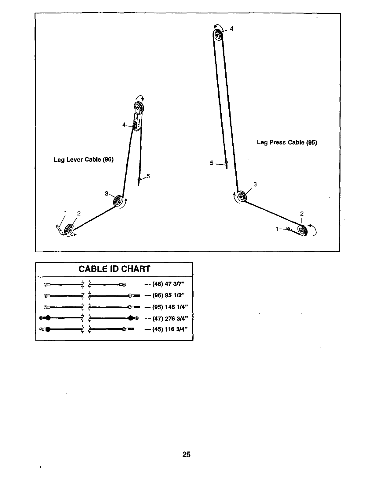
Leg Lever Cable (96)
1 2
f
4_
_5
4
Leg Press Cable (95)
2
CABLE ID CHART
_-- (46) 47 3/7"
_ _ -- (96) 95 112"
_ _ -- (95) 148 1/4"
-_ _ _ -- (47) 276 3/4"
_" _ _- -- (45) 116 3/4"
25
EXERCISE GUIDELINES
THE FOUR BASIC TYPES OF WORKOUTS
Muscle Building
To increase the size and strength of your muscles,
push them close to their maximum capacity. Your mus-
cles will continually adapt and grow as you progres-
sively increase the intensityof your exercise. You can
adjust the intensitylevel of an individual exercise in
two ways:
•by changing the amount of weight used
•by changing the number of repetitions or sets per-
formed. (A "repetition"is one complete cycle of an
exercise, such as one sit-up. A"set" is a series of
repetitions.)
The proper amount of weight for each exercise
depends upon the individual user. You must gauge
your limits and select the amount of weight that is dght
for you. Begin with 3 sets of 8 repetitions for each
exercise you perform. Rest for 3 minutes after each
set. When you can complete 3 sets of 12 repetitions
without difficulty,increase the amount of weight.
Toning
You can tone your muscles by pushing them to a mod-
erate percentage of their capacity. Select a moderate
amount of weight and increase the number of repeti-
tions in each set. Complete as many sets of 15 to 20
repetitions as possible without discomfort. Rest for 1
minute after each set. Work your muscles by complet-
ing more sets rather than by using high amounts of
weight.
Weight Lose
To lose weight, use alow amount of weight and
increase the number of repetitions in each set.
Exercise for 20 to 30 minutes, resting for a maximum
of 30 seconds between sets.
Cross Training
Cross training is an efficient way to get a complete and
well-balanced fitness program. An example of a bal-
anced program is:
•Plan weight training workouts on Monday,
Wednesday, and Friday.
•Plan 20 to 30 minutes of aerobic exercise, such as
cycling or swimming, on Tuesday and Thursday.
•Rest from both weight training and aerobic exemise
for at least one full day each week to give your body
time to regenerate.
The combination of weight training and aerobic exer-
cise will reshape and strengthen your body, plus devel-
op your heart and lungs.
PERSONALIZING YOUR EXERCISE PROGRAM
Determining the exact length of time for each workout,
as well as the number of repetitions or sets completed,
is an individual matter. It is important to avoid overdo-
ing it during the first few months of your exercise pro-
gram. You should progress at your own pace and be
sensitive to your body's signals. If you experience pain
or dizziness at any time while exercising, stop immedi-
ately and begin cooling down. Find out what is wrong
before continuing. Remember that adequate rest and a
proper diet are important factors in any exercise pro-
gram.
WARMING UP
Begin each workout with 5 to 10 minutes of stretching
and lightexercise to warm up. Warming up prepares
your body for more strenuous exercise by increasing
cimulation, raising your body temperature and deliver-
ing more oxygen to your muscles.
WORKING OUT
Each workout should include 6 to 10 different exemis-
es. Select exercises for every major muscle group,
emphasizing areas that you want to develop most. To
give balance and variety to your workouts, vary the
exercises from session to session.
Schedule your workouts for the time of day when your
energy level is the highest. Each workout should be
followed by at least one day of rest. Once you find the
schedule that is dght for you, stick with it.
EXERCISE FORM
Maintaining proper form is an essential part of an
effective exercise program, This requires moving
through the full range of motion for each exemise, and
moving only the appropriate parts of the body.
Exercising in an uncontrolled manner will leave you
feeling exhausted. On the exercise guide accompany-
ing this manual you will find photographs showing the
correct form for several exemises, and a list of the
muscles affected. Refer to the muscle chart on page
27 to find the names of the muscles.
The repetitions in each set should be performed
smoothly and without pausing. The exertion stage of
each repetition should last about half as long as the
return stage. Proper breathing is important. Exhale
during the exertion stage of each repetition and inhale
during the return stroke. Never hold your breath.
26
Rest for a short period of time after each set. The
ideal resting periods are:
•Rest for three minutes after each set for a muscle
building workout.
•Rest for one minute after each set for a toning work-
out.
• Rest for 30 seconds after each set for a weight loss
workout.
Plan to spend the first couple of weeks familiarizing
yourself with the equipment and learning the proper
form for each exercise.
COOLING DOWN
End each workout with 5 to 10 minutes of stretching.
Include stretches for both your arms and legs. Move
slowly as you stretch and do not bounce. Ease into
each stretch gradually and go only as far as you can
without strain. Stretching at the end of each workout
is an effective way to increase flexibility,
STAYING MOTIVATED
For motivation, keep a record of each workout, list the
date, the exercises performed, the weight used, and
the numbers of sets and repetitions completed.
Record your weight and key body measurements at
the end of every month. Remember, the key to
achieving the greatest results is to make exercise a
regular and enjoyable part of your everyday life.
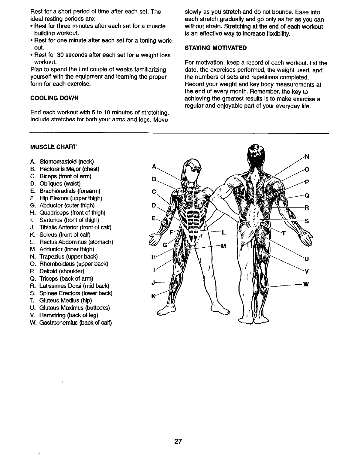
MUSCLE CHART
A. Stamomastoid (neck)
B. PectoralisMajor (chest)
C. Biceps (front of arm)
D. Obliques (waist)
E. Brachioradials(forearm)
F. Hip Flexors (upperthigh)
G. Abductor (outerthigh)
H. Quadriceps (frontof thigh)
LSartodus(front of thigh)
J. TibialisAnterior (front of calf)
K. Soleus (frontof calf)
L. RectusAbdominus(stomach)
M. Adductor (innerthigh)
N. Trapezius (upper back)
O. Rhomboideus (upper back)
P. Deltoid (shoulder)
Q. Triceps (back of arm)
R. LatissimusDomi (mid back)
S. Spinae Erectors (lower back)
T. Gluteus Medius (hip)
U. Gluteus Maximus (buttocks)
V. Hamstring (back of leg)
W. Gastrocnemius back of calf)
R
S
27
This chart is provided to help you identify the small parts used in assembly. The number in parenthesis below
each part refers to the key number of the part from the PART LIST in the center of this manual. Important:
Some parts may have been pre-assembled for shipping, If you cannot find a part In the parts bags,
check to see if It has been pre-aseembled.
Note: Assembly is divided into four stages: 1) frame assembly, 2) arm
assembly, 3) cable assembly, and 4) seat assembly. The hardware for
each stage is packaged separately. Wait until you begin each stage to
open the parts bag for that stage.
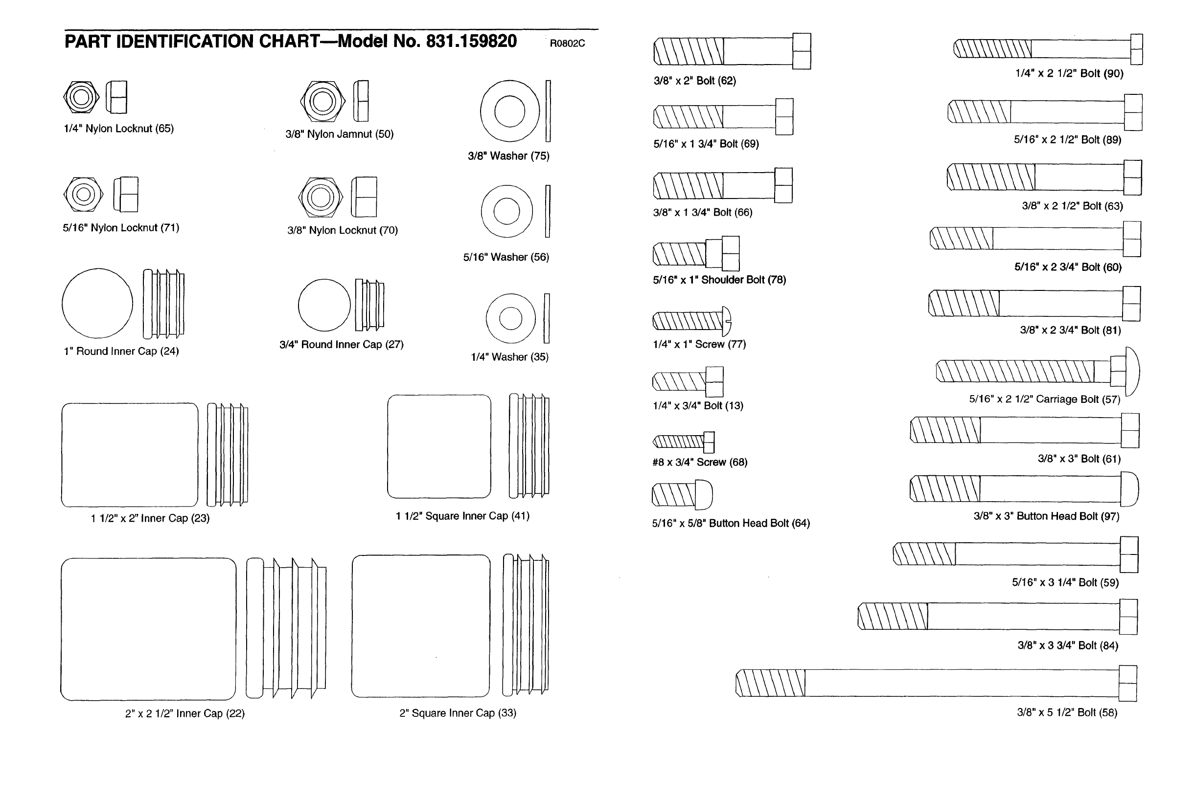
PART IDENTIFICATION CHART--Model No. 831.159820 R0802C
1/4" Nylon Locknut (65) 3/8" Nylon Jamnut (50) 1
3/8" Washer (75)
5/16" Nylon Locknut (71)
1" Round Inner Cap (24)
3/8" Nylon Locknut (70)
3/4" Round Inner Cap (27)
5/16" Washer (56)
1/4" Washer (35)
1/2" x 2" Inner Cap (23)
J
1 1/2" Square Inner Cap (41)
J
2" x 2 1/2" Inner Cap (22)
j
2" Square Inner Cap (33)
3/8" x 2" Bolt (62)
5/16" x 1 3/4" Bolt (69)
3/8" x1 3/4" Bolt (66)
5/16" x 1" Shoulder Bolt (78)
1/4" x 1" Screw (77)
1/4" x 3/4" Bolt (13)
#8 x 3/4" Screw (68)
5/16" x 5/8" Button Head Bolt (64)
1/4" x 2 1/2" Bolt (90)
5/16"x 2 1/2" Bolt (89)
3/8" x 2 1/2" Bolt (63)
5116" x 2 3/4" Bolt (60)
3/8" x 2 3/4" Bolt (81)
5/16" x 2 1/2" Carriage Bolt (57) _
3/8" x 3" Bolt (61)
3/8" x 3" Button Head Bolt (97)
5/16" x 3 1/4" Bolt (59)
3/8" x3 3/4" Bolt (84)
3/8" x 5 1/2" Bolt (58)
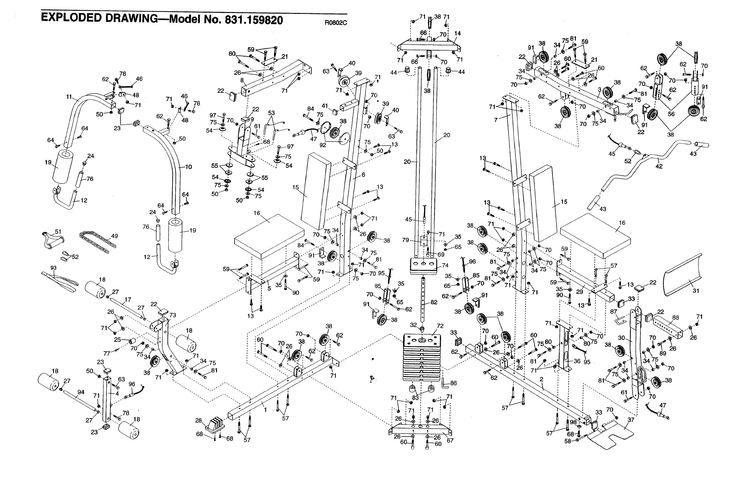
EXPLODED DRAWING--Model No. 831.159820
78
93
18
27 71
22
97 _7 ; /53
'": fTJ.--S68 ,
:-" .--- 97
_..54 15
50"J_ 5(T,e 75
59,
73 .-""
18
16\
R08020
71
84 41
47 92
40
71
70
' 39 4O
:75
63
.6
13
71 p.
38 79
57
7
13
38 71
i
:7O
57
91
71
60
2
59
21
,60 62
38
38
91
62
91
422 38
43
16
57
89
75
88
26
31
71
26
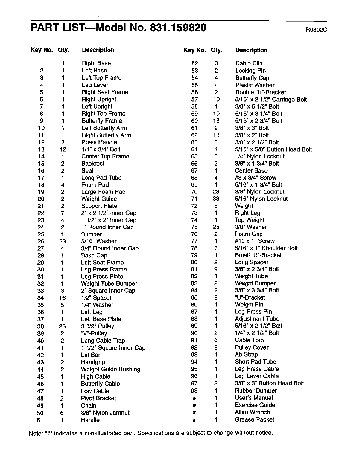
PART LIST--Model No. 831.159820 R08O2C
Key No. Qty. Description Key No. Qty. Description
1 1 Right Base 52 3 Cable Clip
21Left Base 53 2 Locking Pin
3 1 Left Top Frame 54 4 Butterfly Cap
4 1 Leg Lever 55 4 Plastic Washer
5 1 Right Seat Frame 56 2 Double "U"-Bracket
6 1 Right Updght 57 10 5/16" x 2 1/2" Carriage Bolt
7 1 Left Upright 58 1 3/8" x 5 1/2" Bolt
8 1 Right Top Frame 59 10 5/16" x 3 1/4" Bolt
9 1 Butterfly Frame 60 13 5/16" x 2 3/4" Bolt
10 1 Left ButterflyArm 61 2 3/8" x 3" Bolt
11 1 Right Butterfly Arm 62 13 3/8" x 2" Bolt
12 2 Press Handle 63 3 3/8" x 2 1/2" Bolt
13 12 1!4" x 3/4" Bolt 64 4 5/16" x 5/8" Button Head Bolt
14 1 Center Top Frame 65 3 1/4" Nylon Locknut
15 2 Backrest 66 2 3/8" x 1 3/4" Bolt
16 2 Seat 67 1 Center Base
17 1 Long Pad Tube 68 4 #8 x 3/4" Screw
18 4 Foam Pad 69 1 5/16" x 1 3/4" Bolt
19 2 Large Foam Pad 70 28 3/8" Nylon Locknut
20 2 Weight Guide 71 38 5/16" Nylon Locknut
21 2 Support Plate 72 8Weight
22 7 2" x 2 1/2" Inner Cap 73 1 Right Leg
23 4 1 1/2" x 2" inner Cap 74 1Top Weight
24 21" Round Inner Cap 75 25 3/8" Washer
25 1 Bumper 76 2 Foam Grip
26 23 5/16" Washer 77 1 #10 x 1" Screw
27 43/4" Round Inner Cap 78 3 5/16" x 1" Shoulder Bolt
28 1Base Cap 79 1 Small "U"-Bracket
29 1 Left Seat Frame 80 2 Long Spacer
30 1Leg Press Frame 81 9 3/8" x 2 3/4" Bolt
31 1 Leg Press Plate 82 1 Weight Tube
32 1 Weight Tube Bumper 83 2 Weight Bumper
33 3 2" Square Inner Cap 84 2 3/8" x 3 3/4" Bolt
34 16 1/2" Spacer 85 2 "U"-Bracket
35 5 1/4" Washer 86 1Weight Pin
36 1 Left Leg 87 1 Leg Press Pin
37 1 Left Base Plate 88 1 Adjustment Tube
38 23 3 1/2" Pulley 89 1 5/16" x 2 1/2" Bolt
39 2 "V"-Pulley 90 2 1/4" x 2 1/2" Bolt
40 2 Long Cable Trap 91 6 Cable Trap
41 1 1 1/2" Square Inner Cap 92 2 Pulley Cover
42 1 Lat Bar 93 1 Ab Strap
43 2 Handgdp 94 1 Short Pad Tube
44 2 Weight Guide Bushing 95 1Leg Press Cable
45 1 High Cable 96 1 Leg Lever Cable
46 1 Butterfly Cable 97 2 3/8" x 3" Button Head Bolt
47 1 Low Cable 98 1 Rubber Bumper
48 2. Pivot Bracket # 1 User's Manual
49 1 Chain #1 Exemise Guide
50 6 3/8" Nylon Jamnut # 1 Allen Wrench
51 1 Handle # 1 Grease Packet
Note: "#" indicates a non-illustrated part. Specifications are subject to change without notice.
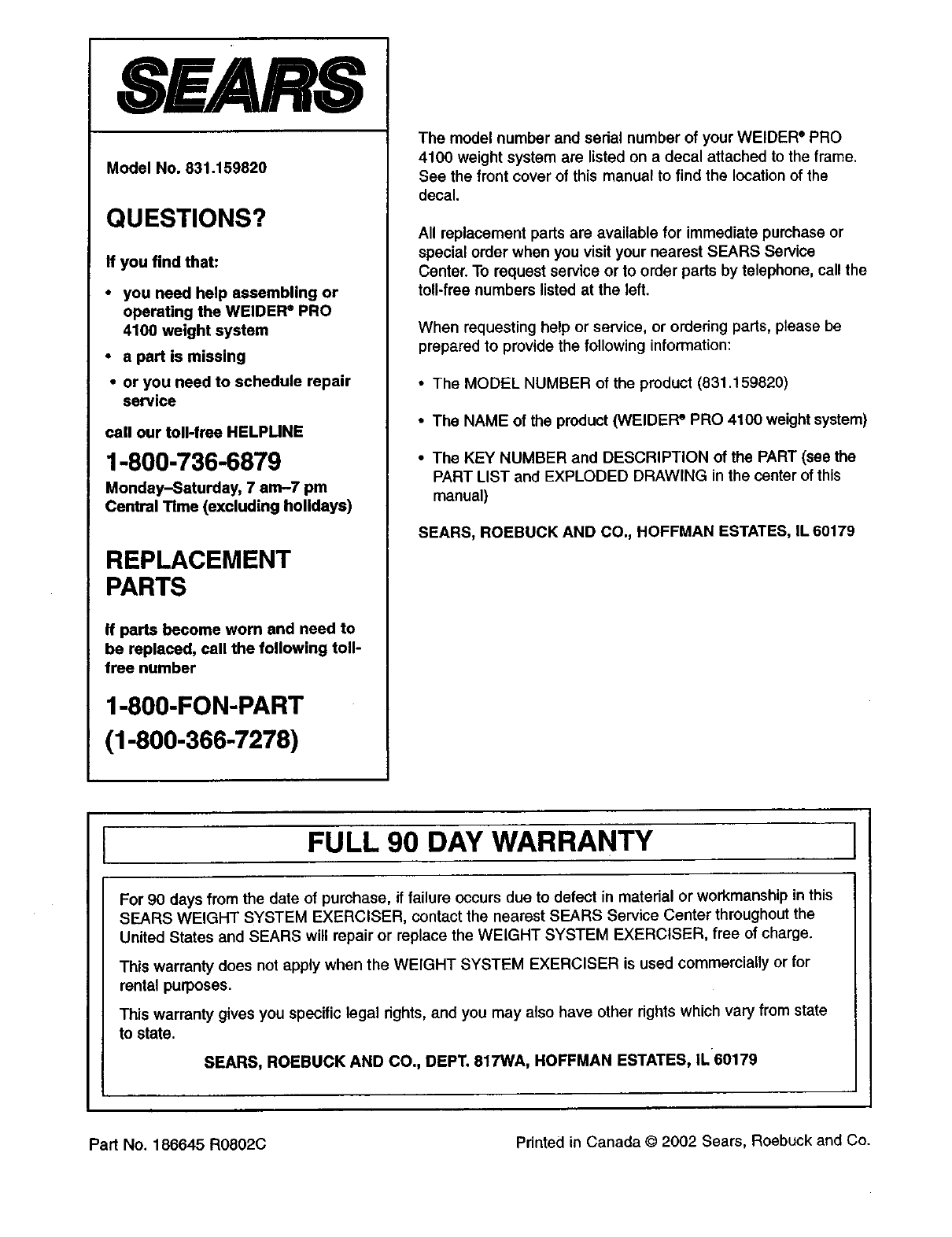
SEARS
Model No. 831.159820
QUESTIONS?
If you find that:
• you need help assembling or
operating the WELDER®PRO
4100 weight system
•a part is missing
• or you need to schedule repair
service
call our toll-free HELPLINE
1-800-736-6879
Monday-Saturday, 7 am-7 pm
Central Time (excluding holidays)
REPLACEMENT
PARTS
If parts become worn and need to
be replaced, call the following toll-
free number
1-800-FON-PART
(1-800-366-7278)
The model number and serial number of your WELDER" PRO
4100 weight system are listed on a decal attached to the frame.
See the front cover of this manual to find the location of the
decal.
All replacement parts are available for immediate purchase or
special order when you visit your nearest SEARS Service
Center. To request service or to order parts by telephone, call the
toll-free numbers listed at the left,
When requesting help or service, or ordering parts, please be
prepared to provide the following information:
• The MODEL NUMBER of the product (831.159820)
• The NAME of the product (WEIDEFP PRO 4100 weight system)
•The KEY NUMBER and DESCRIPTION of the PART (see the
PART LIST and EXPLODED DRAWING in the center of this
manual)
SEARS, ROEBUCK AND CO, HOFFMAN ESTATES, IL 60179
IFULL 90 DAY WARRANTY I
For 90 days from the date of purchase, if failure occurs due to defect in material or workmanship in this
SEARS WEIGHT SYSTEM EXERCISER, contact the nearest SEARS Service Center throughout the
United States and SEARS will repair or replace the WEIGHT SYSTEM EXERCISER, free of charge.
This warranty does not apply when the WEIGHT SYSTEM EXERCISER is used commercially or for
rental purposes.
This warranty gives you specific legal rights, and you may also have other rights which vary from state
to state.
SEARS, ROEBUCK AND CO., DEPT. 817WA, HOFFMAN ESTATES, IL60179
Part No. 186645 R0802C Printed in Canada © 2002 Sears, Roebuck and Co.
