Weider 9025 System Weevsy2023 Users Manual
2015-05-18
: Weider Weider-9025-System-Weevsy2023-Users-Manual-733832 weider-9025-system-weevsy2023-users-manual-733832 weider pdf
Open the PDF directly: View PDF ![]() .
.
Page Count: 31
CAUTION
Read all precautions and instruc-
tions in this manual before using
this equipment. Save this manual
for future reference.
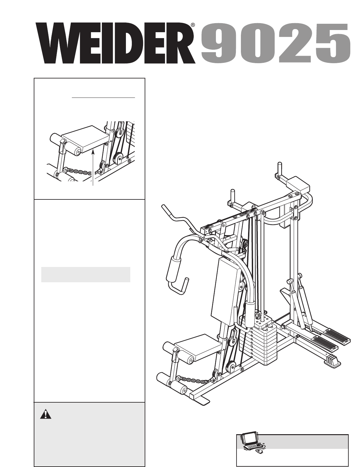
USER'S MANUAL
Model No.WEEVSY20230
Serial No.
Write the serial number in the
space above for reference.
Serial Number Decal (under seat)
QUESTIONS?
As a manufacturer,we are
committed to providing com-
plete customer satisfaction. If
you have questions, or if there
are missing parts, please call:
Or write:
ICON Health & Fitness, Ltd.
Unit 4
Revie Road Industrial Estate
Revie Road
Beeston
Leeds, LS118JG
UK
email: csuk@iconeurope.com
08457 089 009
www.iconeurope.com
Visit our website at
WARNING DECAL PLACEMENT
2
TABLE OF CONTENTS
WARNING DECAL PLACEMENT . . . . . . . . . . . . . . . . . . . . . . . . . . . . . . . . . . . . . . . . . . . . . . . . . . . . . . . . . . . . . .2
IMPORTANT PRECAUTIONS . . . . . . . . . . . . . . . . . . . . . . . . . . . . . . . . . . . . . . . . . . . . . . . . . . . . . . . . . . . . . . . . .3
BEFORE YOU BEGIN . . . . . . . . . . . . . . . . . . . . . . . . . . . . . . . . . . . . . . . . . . . . . . . . . . . . . . . . . . . . . . . . . . . . . . .4
ASSEMBLY . . . . . . . . . . . . . . . . . . . . . . . . . . . . . . . . . . . . . . . . . . . . . . . . . . . . . . . . . . . . . . . . . . . . . . . . . . . . . . .5
ADJUSTMENT . . . . . . . . . . . . . . . . . . . . . . . . . . . . . . . . . . . . . . . . . . . . . . . . . . . . . . . . . . . . . . . . . . . . . . . . . . . .16
WEIGHT RESISTANCE CHART . . . . . . . . . . . . . . . . . . . . . . . . . . . . . . . . . . . . . . . . . . . . . . . . . . . . . . . . . . . . . .18
TROUBLESHOOTING . . . . . . . . . . . . . . . . . . . . . . . . . . . . . . . . . . . . . . . . . . . . . . . . . . . . . . . . . . . . . . . . . . . . . .19
CABLE DIAGRAM . . . . . . . . . . . . . . . . . . . . . . . . . . . . . . . . . . . . . . . . . . . . . . . . . . . . . . . . . . . . . . . . . . . . . . . . .20
EXERCISE GUIDELINES . . . . . . . . . . . . . . . . . . . . . . . . . . . . . . . . . . . . . . . . . . . . . . . . . . . . . . . . . . . . . . . . . . .21
ORDERING REPLACEMENT PARTS . . . . . . . . . . . . . . . . . . . . . . . . . . . . . . . . . . . . . . . . . . . . . . . . . .Back Cover
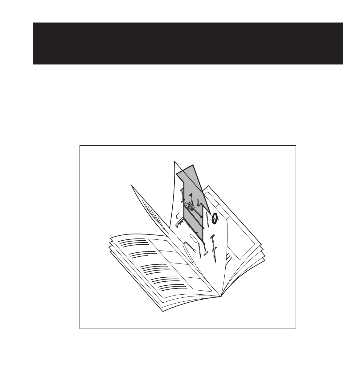
Note: A PART IDENTIFICATION CHART and a PARTS LIST/EXPLODED DRAWING are attached at the centre
of this manual. Remove them before beginning assembly.
151388
Keep hands and
fingers clear of
this area.
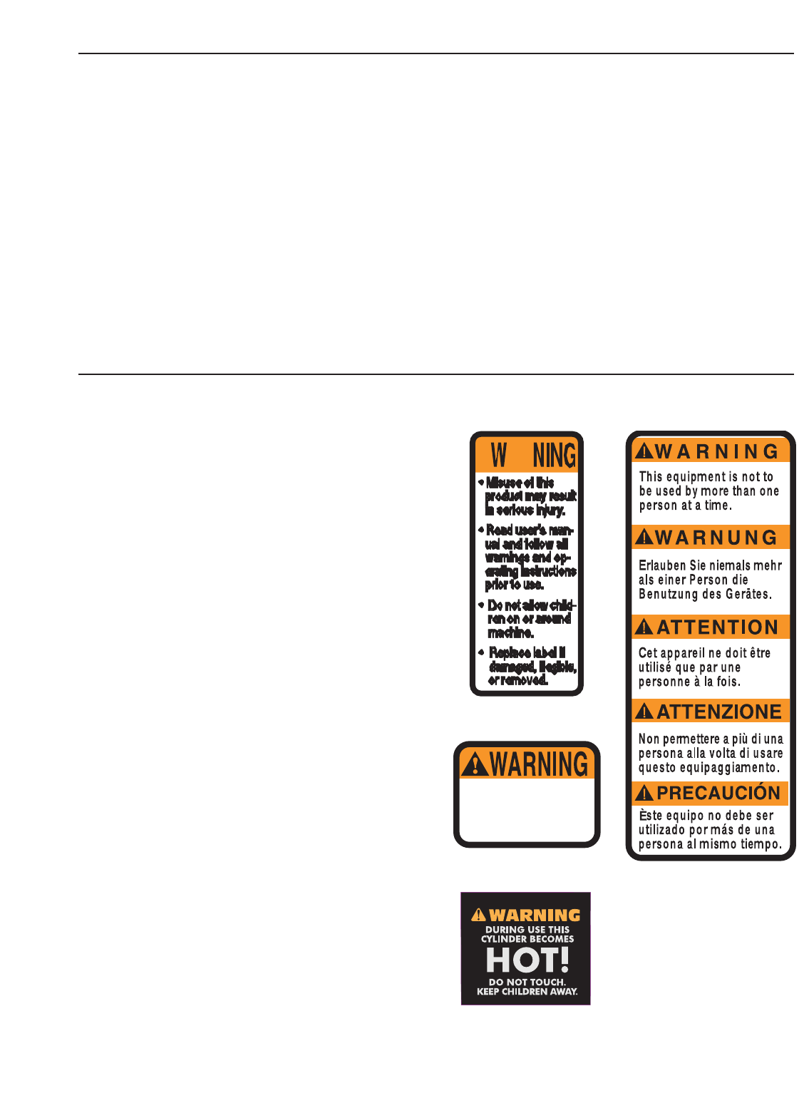
The decals shown here have been placed on the
weight system in the locations shown on page 4. If a
decal is missing or illegible, please call our
Customer Service Department 08457 089 009 to
order a free replacement decal. Apply the decal in
the location shown.
Warning Decal 1
Warning Decal 2 Warning Decal 4
Keep hands and
fingers clear of
this area.
Warning Decal 3

3
IMPORTANT PRECAUTIONS
WARNING:To reduce the risk of serious injury, read the following important precautions
before using the weight system.
1. Read all instructions in this manual and in
the accompanying literature before using the
weight system.
2. It is the responsibility of the owner to ensure
that all users of the weight system are ade-
quately informed of all precautions.
3. The weight system is intended for home use
only. Do not use the weight system in any
commercial, rental, or institutional setting.
4. Use the weight system only on a level sur-
face. Cover the floor beneath the weight sys-
tem to protect the floor.
5. Make sure all parts are properly tightened
each time the weight system is used.
Replace any worn parts immediately.
6. Keep children under 12 and pets away from
the weight system at all times.
7. Keep hands and feet away from moving parts.
8. The weight system is designed to support a
amaximum user weight of 135 kg (300 lbs.).
9. Always wear athletic shoes for foot protection.
10. Always stand on the foot plate when per-
forming an exercise that could cause the
weight system to tip.
11. Never release the press arm, fly arms, leg
lever, lat bar, ankle strap, or handle whilst
weights are raised; the weights will fall with
great force.
12.
Always disconnect the lat bar from the
weight system when performing an exercise
that does not use the lat bar.
13. Make sure that the cables remain on the pul-
leys at all times. If the cables bind whilst you
are exercising, stop immediately and make
sure that the cables are on all of the pulleys.
14. The resistance cylinders become very hot
during use. Allow the cylinders to cool
before touching them.
15. If you feel pain or dizziness at any time
whilst exercising, stop immediately and
begin cooling down.
WARNING: Before beginning this or any exercise program, consult your physician. This
is especially important for persons over the age of 35 or persons with pre-existing health problems.
Read all instructions before using. ICON assumes no responsibility for personal injury or property
damage sustained by or through the use of this product.
4
BEFORE YOU BEGIN
Thank you for selecting the versatile WEIDER®9025
weight system. The weight system offers a selection of
weight stations designed to develop every major mus-
cle group of the body. Whether your goal is to tone
your body, build dramatic muscle size and strength, or
improve your cardiovascular system, the weight sys-
tem will help you to achieve the specific results you
want.
For your benefit, read this manual carefully before
using the weight system. If you have questions after
reading this manual, please call our Customer Service
Department at 08457 089 009. To help us assist you,
please note the product model number and serial num-
ber before calling. The model number is
WEEVSY20230. The serial number can be found on a
decal attached to the weight system (see the front
cover of this manual).
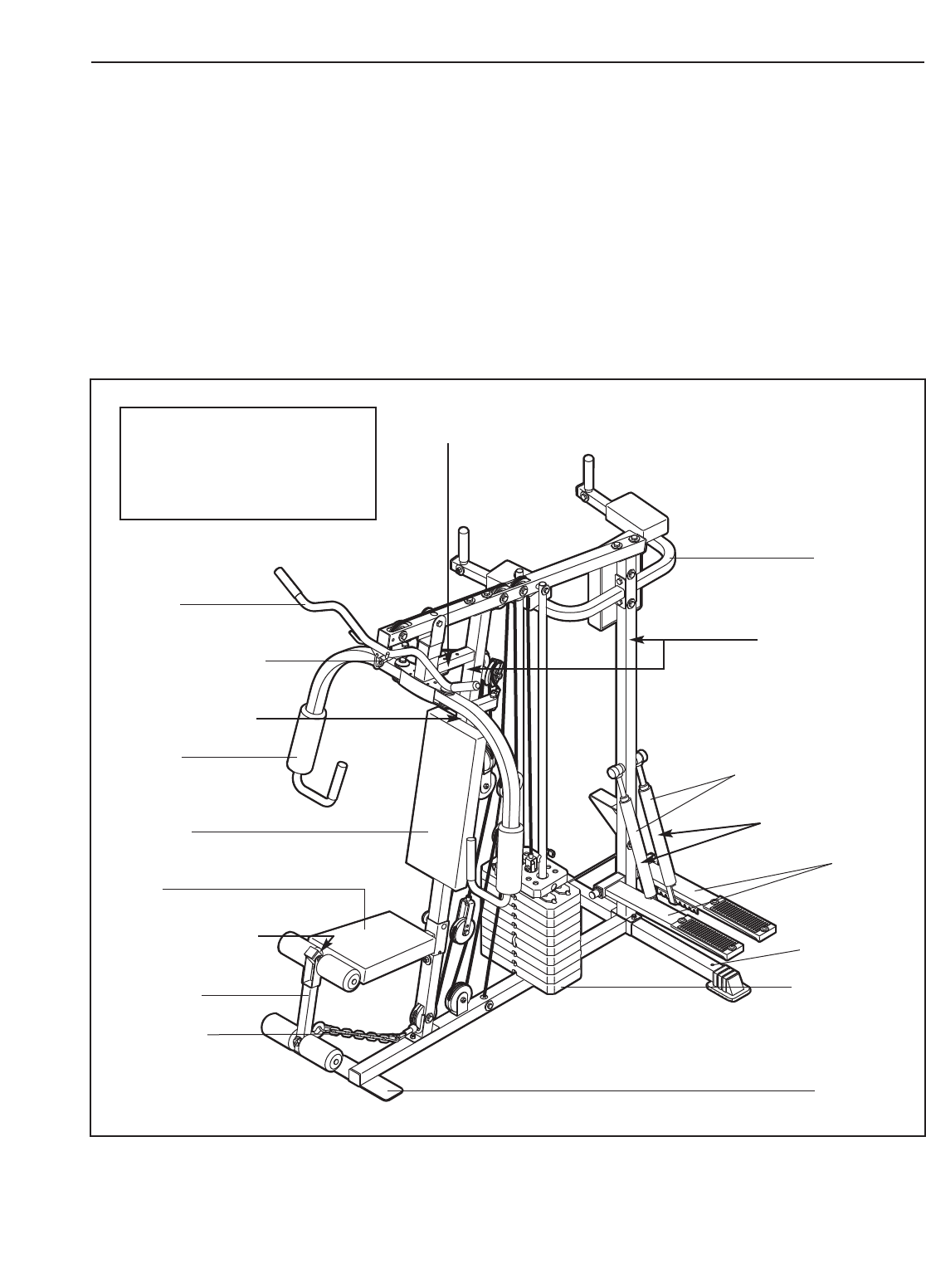
Before reading further, please review the drawing
below and familiarise yourself with the parts that are
labelled.
Foot Plate
Low Pulley
Station
High Pulley Station
Lat Bar
Leg Lever
Fly Arm
Stepper
Weight Stack
Backrest
Resistance Cylinders
VKR Arms
Seat
ASSEMBLED DIMENSIONS:
Height: 188 cm (74 in.)
Width: 120 cm (47 in.)
Depth: 165 cm (65 in.)
Anchor Hole
Warning Decal 4
(One on each side of
the rear upright)
Warning Decal 3
Warning Decal 1
Warning Decal 2
Warning Decal 2
(One on each side of the front upright)
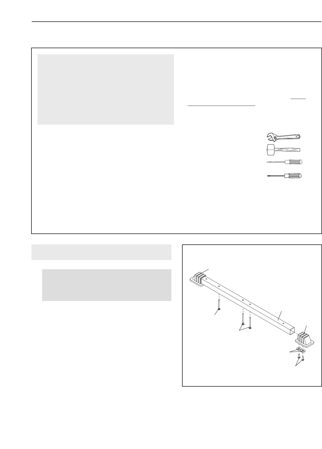
1.
Attach a Base Cap (32) to the Stabiliser (2) with
two M4 Washers (75) and two M4 x 16mm Self-
tapping Screws (74). Attach another Base Cap
to the Stabiliser in the same manner.
Insert two M8 x 67mm Carriage Bolts (82) and an
M10 x 67mm Carriage Bolt (107) up through the
Stabiliser (2). It may be helpful to place a piece
of tape over the bolt head to hold it in place.
5
1
107
32
2
82
75
74
32
Before beginning assembly, carefully read the
following information and instructions:
•Assembly requires two people.
•To make assembly as easy as possible, we have
divided the assembly process into four stages.
The parts needed for each stage are found in
individual bags. Important: Wait until you begin
each stage to open the parts bag for that
stage. Place all parts of the weight system in a
cleared area and remove the packing materials.
Do not dispose of the packing materials until
assembly is completed.
•Tighten all parts as you assemble them, unless
instructed to do otherwise.
•As you assemble the weight system, make sure
all parts are oriented as shown in the drawings.
•For help identifying small parts, use the PART
IDENTIFICATION CHART.
The following tools (not included) are required
for assembly:
• two adjustable spanners
• one rubber mallet
• one standard screwdriver
• one Phillips screwdriver
• lubricant, such as grease or petroleum jelly,
and soapy water.
Assembly will be more convenient if you have a
socket set, a set of open-end or closed-end span-
ners, or a set of ratchet spanners.
Make Things Easier for Yourself
Everything in this manual is designed to ensure
that the weight system can be assembled suc-
cessfully by anyone. However, it is important to
realise that the versatile weight system has
many parts and that the assembly process will
take time. Most people find that by setting aside
plenty of time, assembly will go smoothly.
ASSEMBLY
Before you begin, make sure that you
have carefully read the instructions at the
top of this page.
Frame Assembly
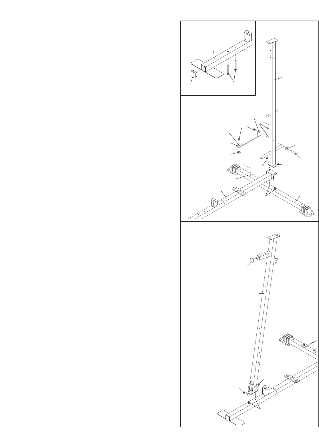
2. See the inset drawing. Press a 50mm Square
Inner Cap (31) into the Base (1). Insert two M10 x
65mm Carriage Bolts (81) up through the Base. It
may be helpful to place a piece of tape over
the bolt head to hold it in place.
Attach the Base (1) and the Rear Upright (3) to
the Stabiliser with the indicated M8 x 67mm
Carriage Bolts (82) and two M8 Nylon Locknuts
(73). Do not tighten the Locknuts yet.
Attach the Support Bracket (33) to the M10 x
67mm Carriage Bolt (107) with an M10 Star
Washer (92) and an M10 Nylon Locknut (72). Do
not tighten the Locknuts yet.
Orient the Support Bracket (33) as shown. Attach
the Support Bracket to the Rear Upright (3) with
an M10 x 72mm Bolt (89), an M10 Washer (71),
and an M10 Nylon Locknut (72). Do not tighten
the Locknuts yet.
2
3
3
81
71
89
73
73
72
33
92
1
31
12
82
107
29
72
81
72
4
6
3. Press a 38mm Square Inner Cap (29) into the
Front Upright (4).
Attach the Front Upright (4) to the Base (1) with
the indicated M10 x 65mm Carriage Bolts (81)
and two M10 Nylon Locknuts (72). Do not tight-
en the Locknuts yet.
Hole
Slot
7
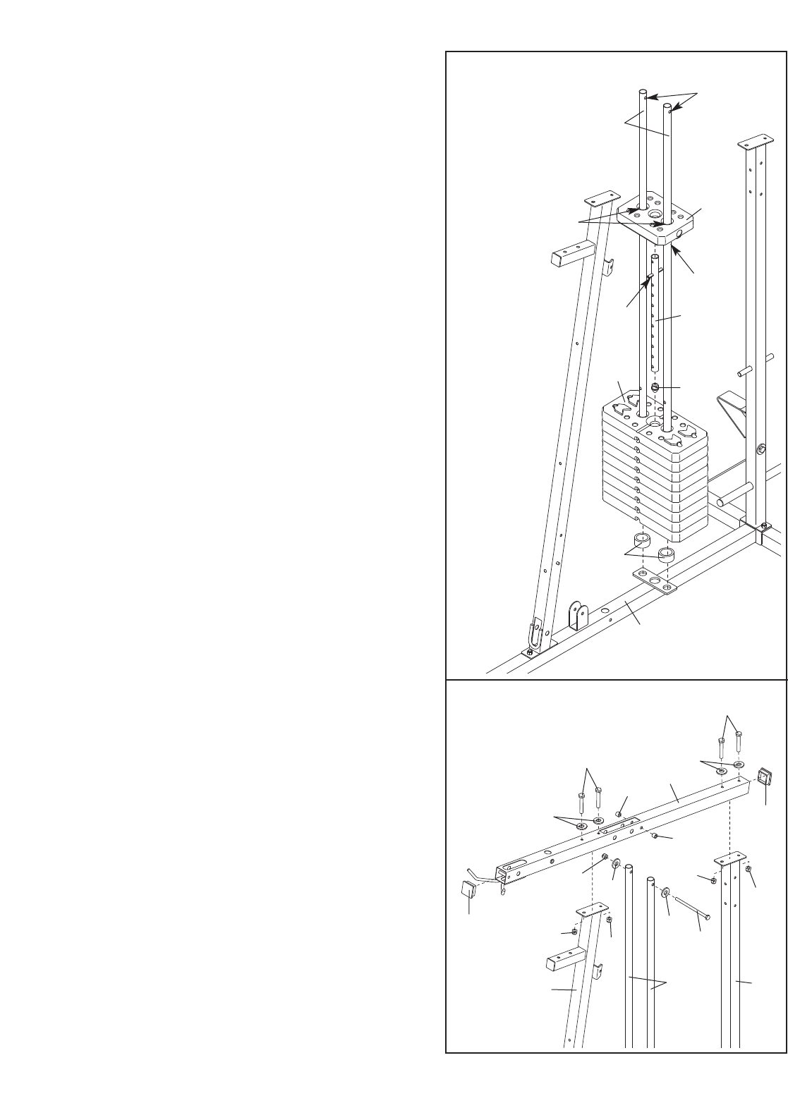
4. Insert two Weight Guides (5) into the Base (1).
Make sure that the holes are on the top.
Slide two Weight Bumpers (44) onto the Weight
Guides (5). Slide the nine Weights (16) onto the
Weight Guides.
Press the Weight Tube Bumper (17) into the
Weight Tube (18). Insert the Weight Tube into the
stack of Weights (16) as shown.
Lubricate the indicated holes in the Top Weight
(19) with grease. Slide the Top Weight onto the
Weight Guides (5). Make sure the pin on the
Weight Tube (18) rests in the pin grooves on
the bottom of the Top Weight.
5. Press two 50mm Square Inner Caps (31) into the
Top Frame (6).
Attach the Top Frame (6) to the Front and Rear
Uprights (4, 3) with four M10 x 68mm Bolts (87),
four M10 Washers (71), and four M10 nylon
Locknuts (72). Do not tighten the Locknuts yet.
Attach the Weight Guides (5) to the Top Frame
(6) with an M10 x 153mm Bolt (91), two M10
Washers (71), two 18mm Spacers (109), and an
M10 Nylon Locknut (72). Do not tighten the
Locknuts yet.
5
4
5
19
Pin
Pin
Groove
Lubricate
Holes
18
17
16
44
1
31
43
5
71
71
91
72
72 72
72
72
109
109
87
71
87
71
31
6
8
6
7
8
Pedal
Axle
Cylinder
Axle
Hook
Warning Decals
Slotted
Brackets
40
39 38
74
75
75
35
14
15
36
98
330
14
37
37
3
72
11
74
83
100
103
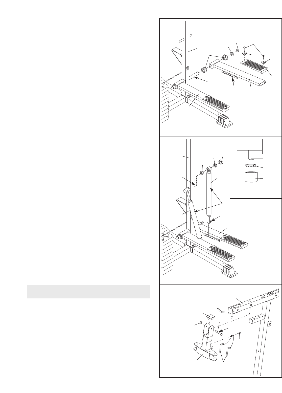
6
Lubricate
6. Press two 38mm Square Bushings (35) into the
Right Pedal (14); Attach a Pedal Cover (36) to the
Pedal with two M4 x 16mm Self-tapping Screws
(74) and two M4 Washers (75).
Lubricate the pedal axles on the Rear Upright (3).
Slide the Right Pedal (14) onto the pedal axle.
Make sure that the Pedal is on the correct
side; the slotted brackets must be on the
inside of the Pedal.
Hold a 25mm Retainer (98) and 25mm Round
Outer Cap (30) against the right pedal axle. The
teeth on the Retainer must bend toward the
Round Cover Cap (see the inset drawing in
step 7). Tap the Retainer and Round Outer Cap
onto the pedal axle.
Attach the Left Pedal (15) in the same manner.
7. Lubricate the cylinder axles on the Rear Upright
(3) with grease.
Slide a 16mm Round Bushing (40) and a
Resistance Cylinder (37) onto the right cylinder
axle. Make sure that the Bushing, Cylinder,
and warning decal are oriented as shown.
Hold a 16mm Retainer (39) and a 16mm Round
Outer Cap (38) against the right cylinder axle.
The teeth on the Retainer must bend toward
the Outer Cap (see the inset drawing). Tap the
Retainer and Outer Cap onto the cylinder axle.
Raise the Right Pedal (14) and rest it on the hook
at the lower end of the Resistance Cylinder (37).
The hook must be in one of the slots under
the right Pedal.
Repeat this step with the other Resistance
Cylinder (37) on the left side of the Rear
Upright (3). Tighten the Nylon Locknuts (72, 73)
used in steps 2–7.
8. Press a 50mm x 70mm Inner Cap (103) into the
Butterfly Frame (11).
Attach the tethers on the two “L”-pins (100) to the
Butterfly Frame (11) with an M4 x 16mm Self-tap-
ping Screw (74).
Lubricate an M10 x 80mm Bolt (83) with grease.
Attach the Butterfly Frame (11) to the Top Frame
(6) with the Bolt and an M10 Nylon Locknut (72).
Do not overtighten the Locknut; the Butterfly
Arm must be able to pivot easily.
30, 38
Axle
39, 98
Arm Assembly
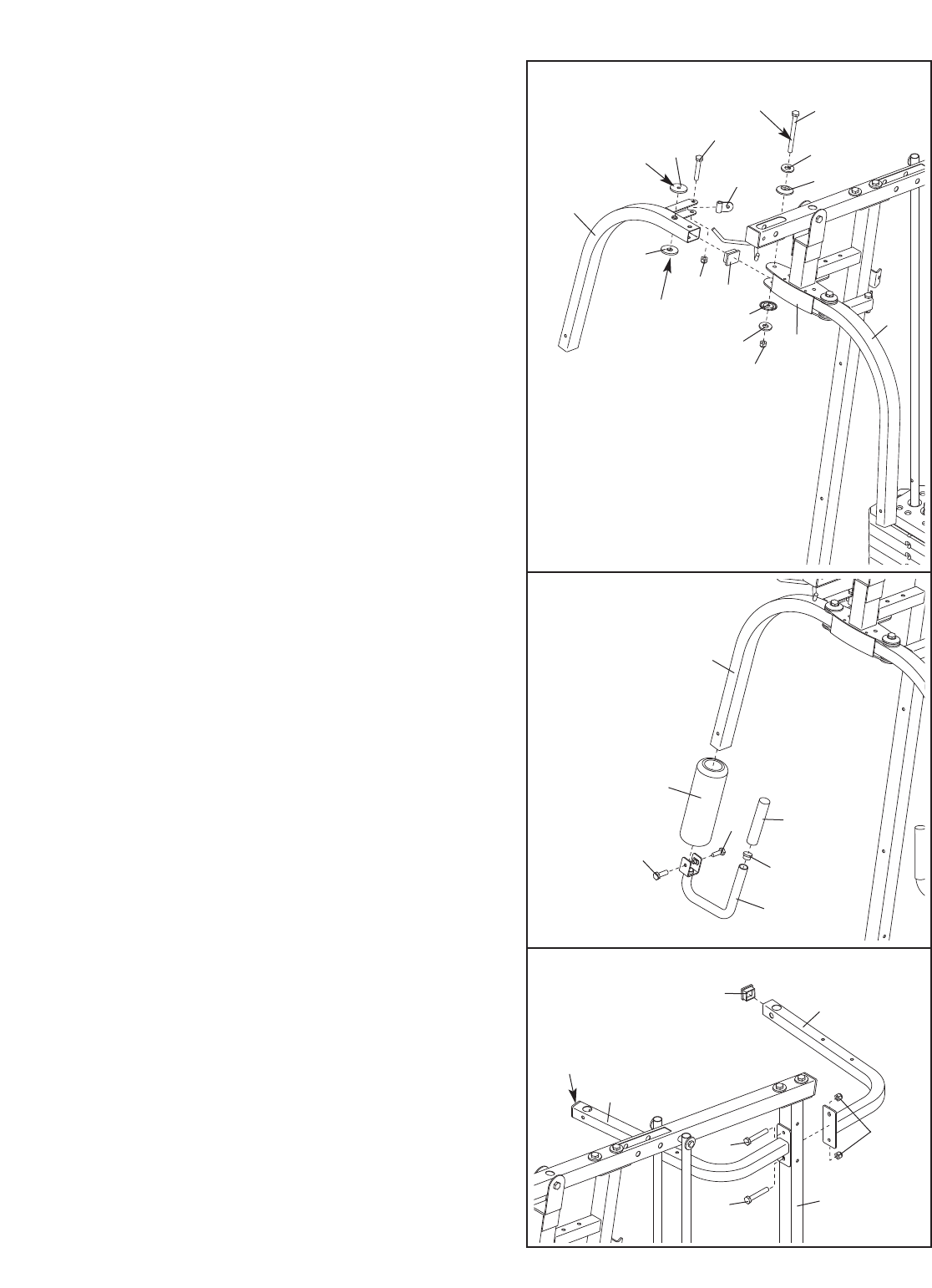
9
9. Attach a Cable Pivot (58) to the Right Fly Arm (9)
with an M10 x 50mm Bolt (85) and an M10 Nylon
Locknut (72). Do not overtighten the Locknut; the
Cable Pivot must be able to pivot easily.
Press a 40mm x 50mm Inner Cap (23) into the
Right Fly Arm (9).
Lubricate an M10 x 83mm Button Head Bolt (86)
and the flat sides of two Plastic Washers (59) with
grease. Attach the Right Fly Arm (9) to the indi-
cated side of the Butterfly Frame (11) with the
Bolt, two M10 Washers (71), two Butterfly Caps
(60), the two Plastic Washers, and an M10 Nylon
Locknut (72). Do not overtighten the Locknut;
the Fly Arm must be able to pivot easily.
Assemble the Left Fly Arm (10) in the same
manner.
10. Wet the lower end of the Right Fly Arm (9) with
soapy water. Slide a Large Foam Pad (65) onto
the Fly Arm.
Attach an Arm Handle (24) to the Right Fly Arm
(9) with two M8 x 20mm Button Head Bolts (84).
Press a 25mm Dome Inner Cap (25) into the
Right Fly Arm (9). Slide a Long Handgrip (102)
onto the Fly Arm.
Slide the Large Foam Pad (65) down so that it
is aligned with the bottom of the Right Fly
Arm (9).
Repeat this step with the Left Fly Arm (not
shown).
11. Press two 38mm Square Inner Caps (29) into the
Right and Left VKR Arms (12, 13).
Attach the Right and Left VKR Arms (12, 13) to
the Rear Upright (3) with two M10 x 72mm Bolts
(89) and two M10 Nylon Locknuts (72).
11
29
29
13
12
72
3
89
89
9
9
65
84
84 102
Lubricate
Lubricate
Lubricate
72
23
11
10
85
58
86
71
71
60
60
72
59
9
59
10
24
25
10
12. Slide a Grip (41) onto a VKR Handle (42). Attach
the VKR Handle to the Left VKR Arm (13) with an
M10 x 55mm Bolt (80), two M10 Washers (71), a
7mm Spacer (43), and an M10 Nylon Locknut
(72).
Press a 25mm
Round
Inner Cap (105) into the
bottom of the VKR Handle (42).
Repeat this step with the Right VKR Arm (12).
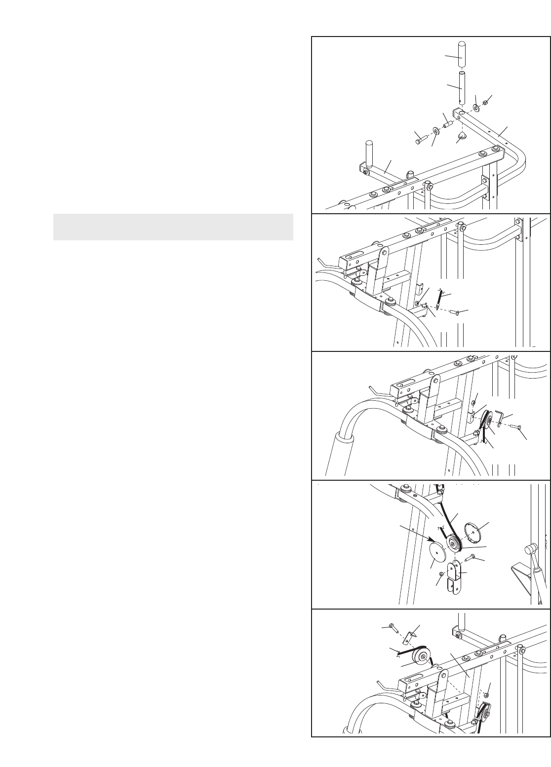
13. Locate the Butterfly Cable (55). Attach the
Cable to the indicated Cable Pivot (58) with an
M8 x 20mm Shoulder Bolt (93) and an M8 Nylon
Locknut (73).
14. Wrap the Butterfly Cable (55) over a “V”-pulley
(47). Attach the “V”-pulley and a Cable Trap (48)
to the Front Upright (4) with an M10 x 60mm Bolt
(95) and an M10 Nylon Locknut (72).
16. Wrap the Butterfly Cable (55) over a “V”-pulley
(47). Attach the “V”-pulley and a Cable Trap (48)
to the Front Upright (4) with an M10 x 60mm Bolt
(95) and an M10 Nylon Locknut (72).
15. Wrap the Butterfly Cable (55) under a 90mm
Pulley (46). Attach the Pulley and two Pulley
Covers (49) to the Double “U”-bracket (51) with
an M10 x 53mm Bolt (88) and an M10 Nylon
Locknut (72). Make sure the small tabs on the
Pulley Covers are on the top.
15
Small
Tab
13
14
16
12
71
71 72
41
42
105
80
43
13
12
58
93
95
48
47
72
4
55
73
49
88
55
46
49 51
55
95 48
47 72
4
55
Cable Assembly
72
11
20
21
18
17
19
89
94
49 49
72 51
88
46
94
94
53
57
54
54
71
71
72 6
87
46
73
71
72
4
93
73
55
58
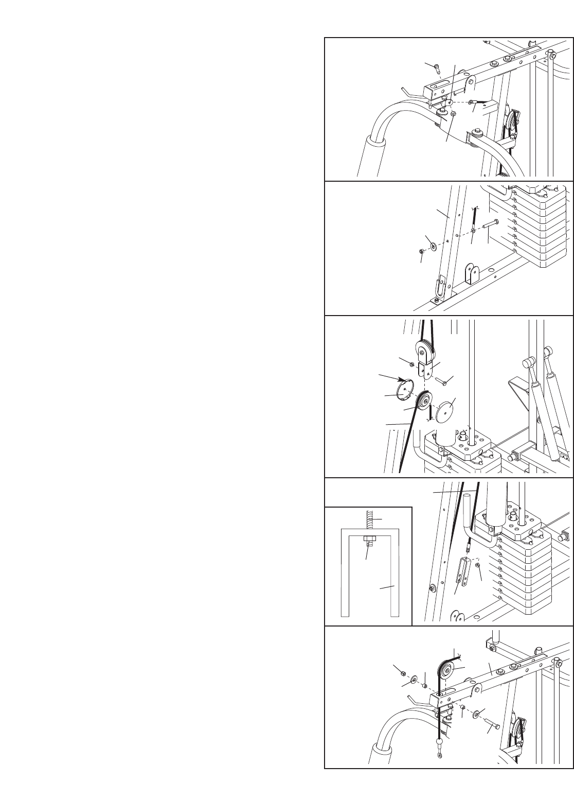
18. Locate the Short Cable (94). Attach the Cable to
the Front Upright (4) with an M10 x 72mm Bolt
(89), an M10 Washer (71), and an M10 Nylon
Locknut (72).
17. Attach the Butterfly Cable (55) to the indicated
Cable Pivot (58) with an M8 x 20mm Shoulder
Bolt (93) and an M8 Nylon Locknut (73).
19. Wrap the Short Cable (94) under a 90mm Pulley
(46). Attach the Pulley and two Pulley Covers (49)
to the Double “U”-bracket (51) with an M10 x
53mm Bolt (88) and an M10 Nylon Locknut (72).
Make sure the large tabs on the Pulley Covers
are on the top.
20. Attach the Short Cable (94) to the “U”-bracket
(53) with an M8 Nylon Locknut (73). Thread the
Locknut onto the end of the Cable so that two
threads show past the Locknut (see the inset
drawing).
21. Locate the High Cable (57). Route the Cable up
through the Top Frame (6) and over a 90mm
Pulley (46). Attach the Pulley inside the Top
Frame with an M10 x 68mm Bolt (87), two M10
Washers (71), two 12mm Spacers (54), and an
M10 Nylon Locknut (72).
Large
Tab
53
73
94
12
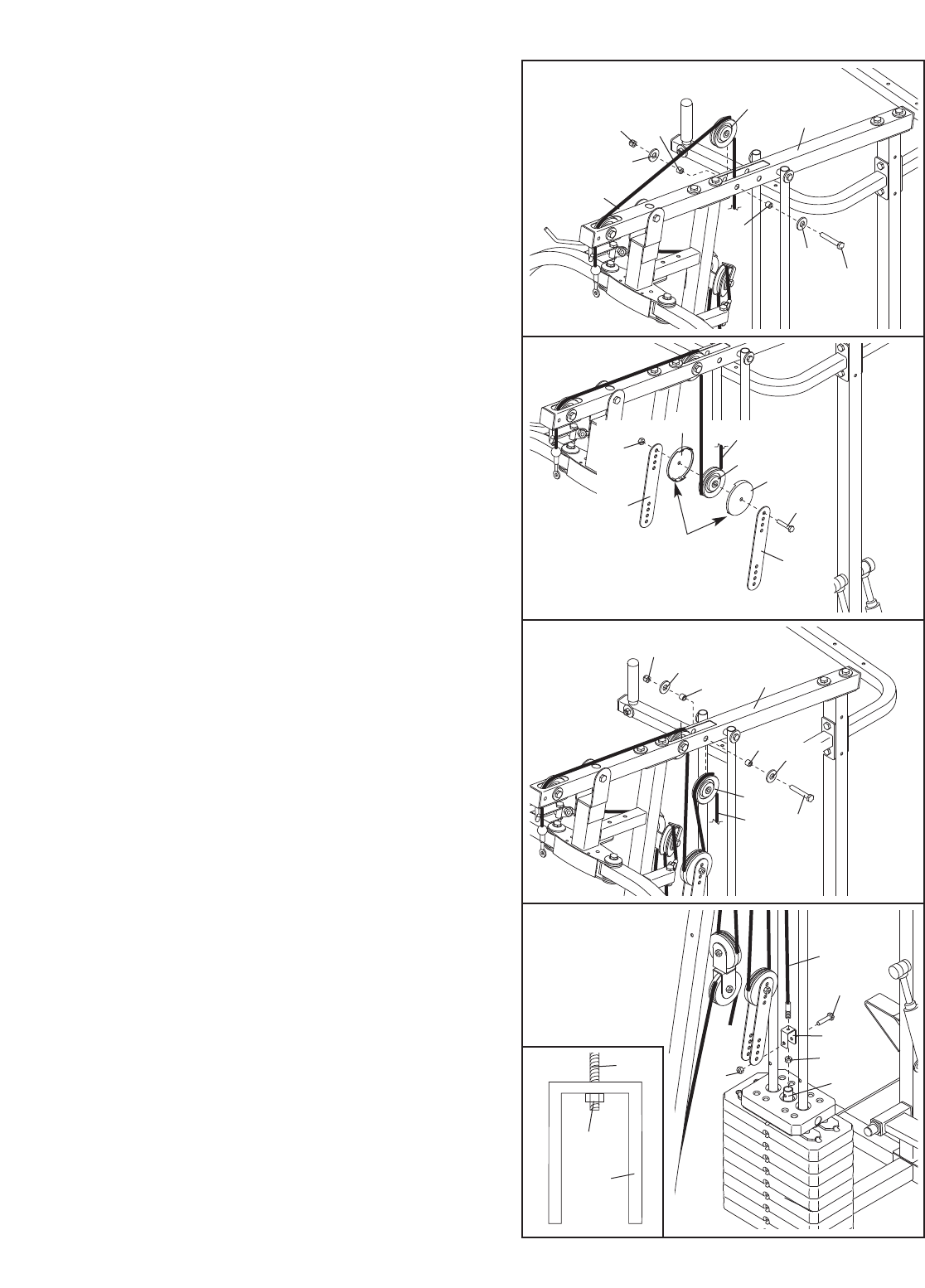
22. Route the High Cable (57) over a 90mm Pulley
(46) and down through the Top Frame (6). Attach
the Pulley inside the Top Frame with an M10 x
68mm Bolt (87), two M10 Washers (71), two
12mm Spacers (54), and an M10 Nylon Locknut
(72).
23. Route the High Cable (57) under a 90mm Pulley
(46). Attach the Pulley and two Pulley Covers (49)
to the upper set of holes in the two Pulley Plates
(50) with an M10 x 53mm Bolt (88) and an M10
Nylon Locknut (72). Make sure the large tabs
on the Pulley Covers are on the bottom.
24. Route the High Cable (57) over a 90mm Pulley
(46). Attach the Pulley inside the Top Frame (6)
with an M10 x 68mm Bolt (87), two M10 Washers
(71), two 12mm Spacers (54), and an M10 Nylon
Locknut (72).
25. Attach the High Cable (57) to the Small “U”-
bracket (52) with an M8 Nylon Locknut (73).
Thread the Locknut onto the end of the Cable
so that two threads show past the Locknut
(see the inset drawing).
Attach the Small “U”-bracket (52) to the Weight
Tube (18) with an M8 x 45mm Bolt (96) and an
M8 Nylon Locknut (73). Do not overtighten the
Locknut; the Weight Tube must be able to
pivot freely.
25
57
96
52
73
73 18
22
23
87
6
57
71
50
Large
Tab 50
72
49
49
88
46
57
72 54
71
54
24 72 71
71
54 6
54
46
57 87
46
52
73
57
13
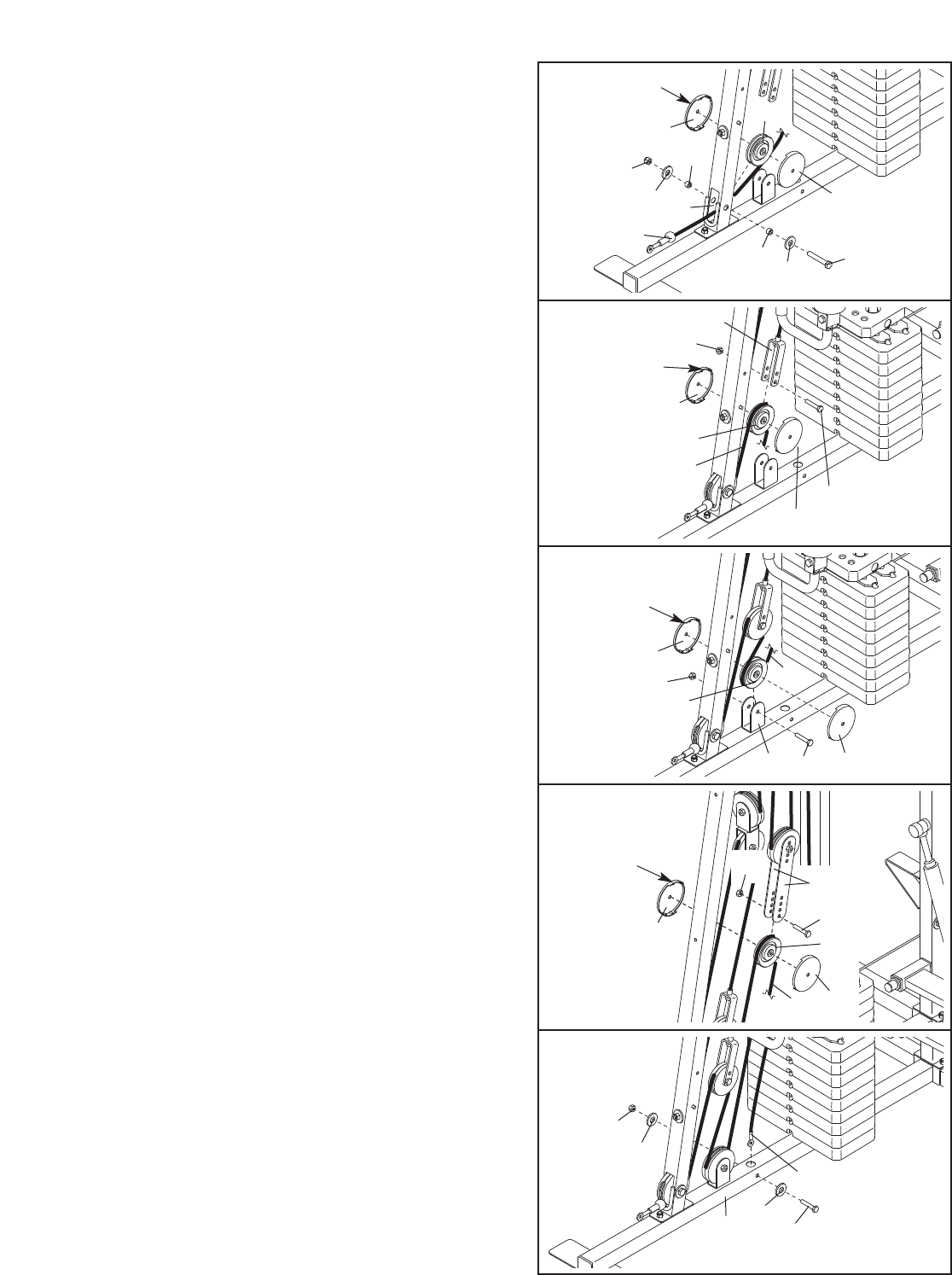
26. Locate the Low Cable (56). Route the Cable
through the Front Upright (4) and under a 90mm
Pulley (46). Attach the Pulley and two Pulley
Covers (49) inside the Upright with an M10 x
68mm Bolt (87), two M10 Washers (71), two
10mm Spacers (45), and an M10 Nylon Locknut
(72). Make sure the large tabs on the Pulley
Covers are in the indicated position.
27. Route the Low Cable (56) over a 90mm Pulley
(46). Attach the Pulley and two Pulley Covers (49)
to the bottom set of holes in the “U”-bracket (53)
with an M10 x 53mm Bolt (88) and an M10 Nylon
Locknut (72). Make sure the large tabs on the
Pulley Covers are on the top.
29. Route the Low Cable (56) over a 90mm Pulley
(46). Attach the Pulley and two Pulley Covers (49)
to the first set of holes from the bottom of the
Pulley Plates (50) with an M10 x 53mm Bolt (88)
and an M10 Nylon Locknut (72). Make sure the
large tabs on the Pulley Covers are on the
top.
30. Attach the Low Cable (56) inside the Base (1)
with an M10 x 68mm Bolt (87), two M10 Washers
(71), and an M10 Nylon Locknut (72).
28. Wrap the Low Cable (56) under a 90mm Pulley
(46). Attach the Pulley and two Pulley Covers (49)
to the Base (1) with an M10 x 53mm Bolt (88)
and an M10 Nylon Locknut (72). Make sure the
small tabs on the Pulley Covers are on the
top.
29
49
49
46
56
72
88
50
30
Large
Tab
Large
Tab
87
4
56
49
56
46
49
88
49
4946
72
71
71
45
45
26
27
28
Large
Tab
Small
Tab
72
1
46
49
88
49 56
87
71
71
72
56
1
72
53

14
31. Attach a VKR Arm Pad (64) to the Left VKR Arm
(13) with two M6 x 53mm Screws (70) and two
M6 Washers (69).
Repeat this step with the Right VKR Arm (12).
32. Attach a VKR Back Pad (63) to the Rear Upright
(3) with two M6 x 65mm Screws (77) and two M6
Washers (69).
33. Attach the Backrest (61) to the Front Upright (3)
with two M6 x 65mm Screws (77) and two M6
Washers (69).
34. Press a 38mm Square Inner Cap (29) into the
Seat Frame (7).
Attach the Seat Plate (28) to the Seat Frame (7)
with an M6 x 50mm Carriage Bolt (78), an M6
Washer (69), and an M6 Nylon Locknut (90) as
shown. Do not tighten the Locknut yet.
Attach the Seat (62) to the Seat Plate (28) with
two M6 x 16mm Screws (76). Next, attach the
Seat to the Seat Frame (7) with an M6 x 53mm
Screw (70) and an M6 Washer (69).
Tighten the M6 Nylon Locknut (90).
31
32
33
34
64
13
12
69
69
70
70
63
3
69
77
61
469
69
77
77
62
78
28
29
7
76
69
90
70
Seat Assembly
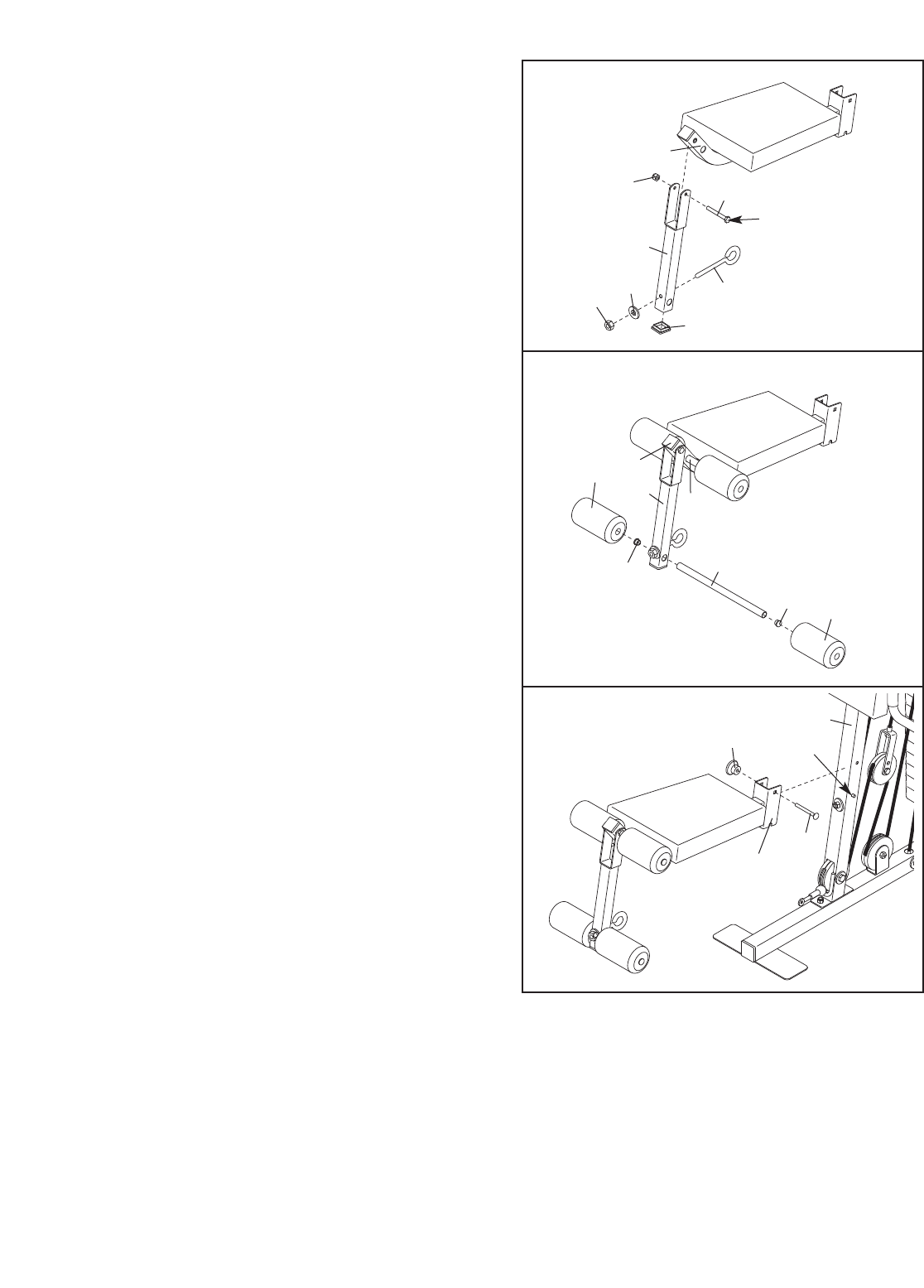
35. Press a 38mm Square Inner Cap (29) into the
Leg Lever (8).
Attach the M10 x 63mm Eyebolt (97) to the Leg
Lever (8) with an M10 Large Washer (108) and
an M10 Nylon Locknut (72).
Lubricate an M8 x 57mm Bolt (79) with grease.
Attach the Leg Lever (8) to the Seat Frame (7)
with the Bolt and an M8 Nylon Locknut (73). Do
not overtighten the Locknut; the Leg Lever
must be able to pivot easily.
36. Press two 19mm Round Inner Caps (27) into a
Pad Tube (26). Slide the Pad Tube into the hole
in the Leg Lever (8). Slide two Small Foam Pads
(66) onto the Pad Tube.
Assemble the other Pad Tube (26) to the Seat
Frame (7) in the same manner.
37. Set the Seat Frame (7) on the pin on the Front
Upright (4). Secure the Seat Frame with an M8 x
67mm Carriage Bolt (82) and the M8 Knob (106).
35
36
37
79
Lubricate
72 108
29
73
7
97
8
26
27
27 66
66 8
7
26
7
106 Pin
82
4
38. Make sure that all parts are properly tightened. The use of all remaining parts will be explained in ADJUST-
MENT,beginning on the following page. Before using the weight system, pull each cable a few times to
make sure that the cables move smoothly over the pulleys. If one of the cables does not move smoothly,
locate and correct the problem before using the weight system. IMPORTANT: If the cables are not proper-
ly routed, they may be damaged when heavy weight is used. See the CABLE DIAGRAM on page 20
of this manual.
15
16
ADJUSTMENT
The instructions below describe how each part of the weight system can be adjusted. IMPORTANT: When
attaching the lat bar or handle, make sure that the accessories are in the correct starting position for the
exercise to be performed. If there is any slack in the cable or chain as an exercise is performed, the
effectiveness of the exercise will be reduced.
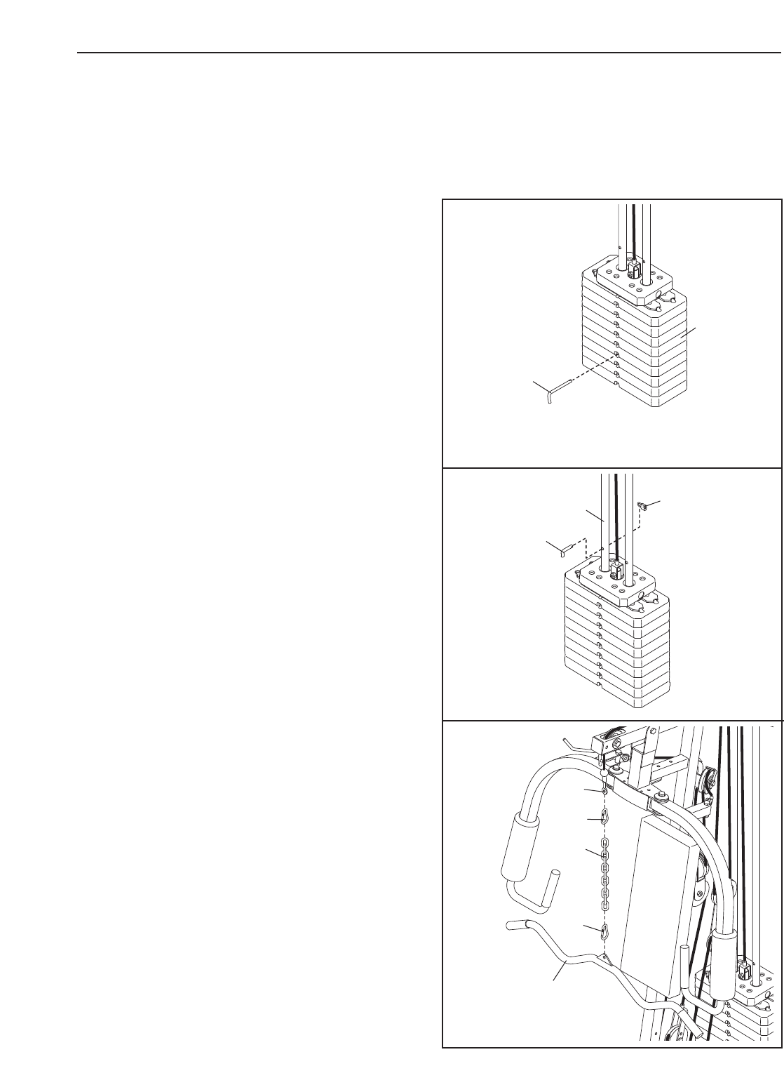
CHANGING THE WEIGHT SETTING
To change the weight setting, insert the Weight Pin
(20) under one of the Weights (16). Make sure to
insert the Weight Pin until the bent end of the Weight
Pin is touching the Weights, and turn the bent end
downward. The weight setting can be changed from
12.5 pounds to 125 pounds, in increments of 12.5
pounds. Important: Due to the cables and pulleys,
the actual amount of resistance at each exercise
station will vary from the weight setting. Refer to
the WEIGHT RESISTANCE CHART on page 18 to
find the actual amount of resistance at each sta-
tion. Note: 1 kg = 2,2 pounds.
LOCKING THE WEIGHT STACK
To prevent unauthorised use of the weight system,
insert the Locking Bar (21) into the indicated hole in
one of the Weight Guides (5). Secure the Locking Bar
with the Lock (22).
Remove the Lock (22) and Locking Bar (21) to use
the weight system again.
ATTACHING THE ACCESSORIES TO A PULLEY
STATION
Attach the Lat Bar (101) to the High Cable (57) with a
Cable Clip (68). For some exercises, the Chain (99)
should be attached between the Lat Bar and the High
Cable with two Cable Clips. Adjust the length of the
Chain between the Lat Bar and the High Cable so
that the Lat Bar is in the correct starting position
for the exercise to be performed.
The Handle (not shown) can be attached in the same
manner. The accessories can be attached to the Low
Cable (not shown) in the same manner.
20
16
522
21
68
68
101
99
57
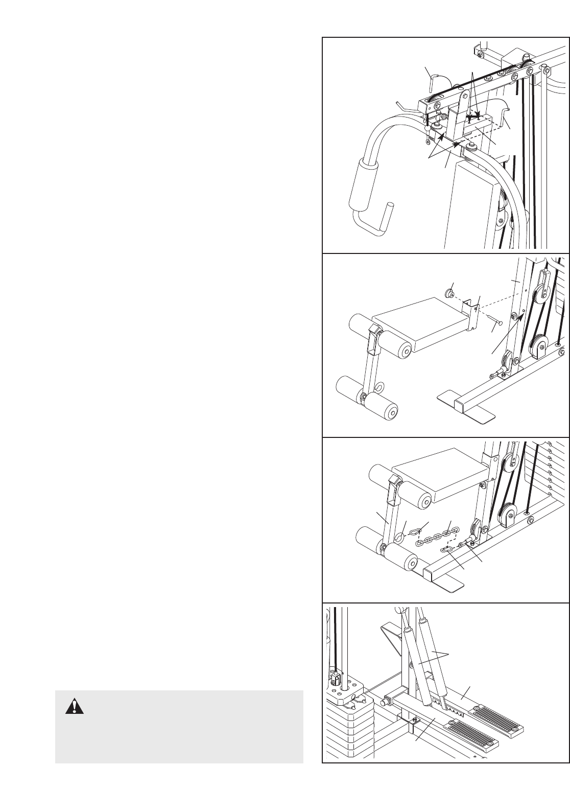
CONVERTING THE BUTTERFLY ARMS
Touse the Fly Arms (9, 10) as butterfly arms, insert
the “L”-pins (100) into the butterfly holes in the Front
Upright (4) and the tab on the back of the Butterfly
Frame (11).
To use the Fly Arms (9, 10) as press arms, insert the
“L”-pins (100) into the press holes in the Butterfly
Frame (11).
Make sure that the “L”-pins (100) are fully inserted
into the same set of holes before performing any
exercises.
ATTACHING THE SEAT
Set the Seat Frame (7) on the pin on the Front
Upright (4). Secure the Seat Frame with an M8 x
67mm Carriage Bolt (82) and the M8 Knob (106).
For some exercises, the Seat (7) must be removed.
First, make sure that the chain is not attached to the
leg lever (see ATTACHING THE LEG LEVER,below).
Next, remove the M8 Knob (106) and M8 x 67mm
Carriage Bolt (82) from the Seat Frame. Lift the Seat
Frame offthe Front Upright (4).
ATTACHING THE LEG LEVER
To use the Leg Lever (8), first attach the seat to the
weight system (see ATTACHING THE SEAT, above).
Next attach the Low Cable (56) to the M10 x 63mm
Eyebolt (97) with the Chain (99) and two Cable Clips
(68).
CHANGING THE STEPPING RESISTANCE
To change the stepping resistance, lift the Right and
Left Pedals (14, 15) off the hooks at the lower ends of
the Resistance Cylinders (37). Move the hooks to dif-
ferent slots under the Pedals. Make sure that the
hooks are fully inserted into the slots in the same
position under both Pedals. The farther the hooks
are moved from the Rear Upright (3), the greater the
resistance will be.
100
11
4
100 Butterfly
Press
97
8
56
68
68
99
106
82
74
Pin
37
14
15
17
WARNING:The Resistance
Cylinders (37) become very hot during use.
Allow the Resistance Cylinders to cool before
touching them.

18
WEIGHT
Top
1
2
3
4
5
6
7
8
9
HIGH PULLEY
(lbs.)
13
31
47
64
77
87
106
128
138
154
PRESS ARM
(lbs.)
25
44
67
81
101
118
135
158
183
197
BUTTERFLY
ARM
(lbs.)
18
33
52
62
76
86
98
114
125
139
LEG LEVER
(lbs.)
13
26
40
53
65
75
91
106
117
134
LOW PULLEY
(lbs.)
15
34
48
64
78
90
103
120
137
153
WEIGHT RESISTANCE CHART
The chart below shows the approximate weight resistance at each exercise station. “Top” refers to the 6 lb. top
weight. The other numbers refer to the 12.5 lb. weight plates. Weight resistance shown for the butterfly arm sta-
tion is for each butterfly arm. Note: The actual resistance at each station may vary due to differences in
individual weight plates as well as friction between the cables, pulleys, and weight guides.
Note: 1 kg = 2,2 pounds.
19
TROUBLESHOOTING
Make sure all parts are properly tightened each time the weight system is used. Replace any worn parts immedi-
ately. The weight system can be cleaned using a damp cloth and mild non-abrasive detergent. Do not use solvents.
TIGHTENING THE CABLES
Woven cable, the type of cable used on the weight system, can stretch slightly when it is first used. If there is
slack in the cables before resistance is felt, the cables should be tightened. Slack can be removed from the
cables in several different ways.
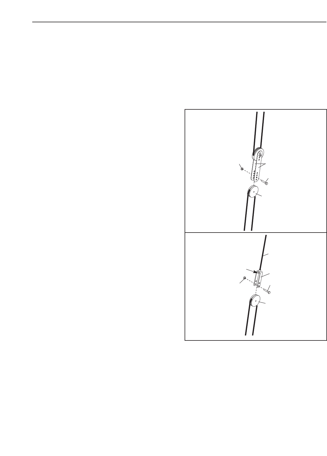
TIGHTENING THE PULLEY PLATES
Slack can be removed by moving a 90mm Pulley (not
shown) and the Pulley Covers (49) to a set of holes
closer to the centre of the two Pulley Plates (50).
Remove the M10 Nylon Locknut (72) and the M10 x
53mm Bolt (88) from the Pulley Covers, the Pulley,
and the Pulley Plates. Re-attach the Pulley and the
Pulley Covers to the new set of holes in the Pulley
Plates with the Bolt and Locknut.
TIGHTENING THE “U”-BRACKET
Slack can be removed by moving the 90mm Pulley
(not shown) and the Pulley Covers (49) to the upper
set of holes in the “U”-bracket (53). Remove the M10
Nylon Locknut (72) and the M10 x 53mm Bolt (88)
from the Pulley Covers, the Pulley,and the “U”-brack-
et. Re-attach the Pulley and the Pulley Covers to the
new set of holes in the “U”-bracket with the Bolt and
Locknut.
Slack can also be removed from the Short Cable (94)
by tightening the M8 Nylon Locknut (73) a couple of
turns onto the Short Cable.
50
49
72
88
72
73 53
94
88
49
20
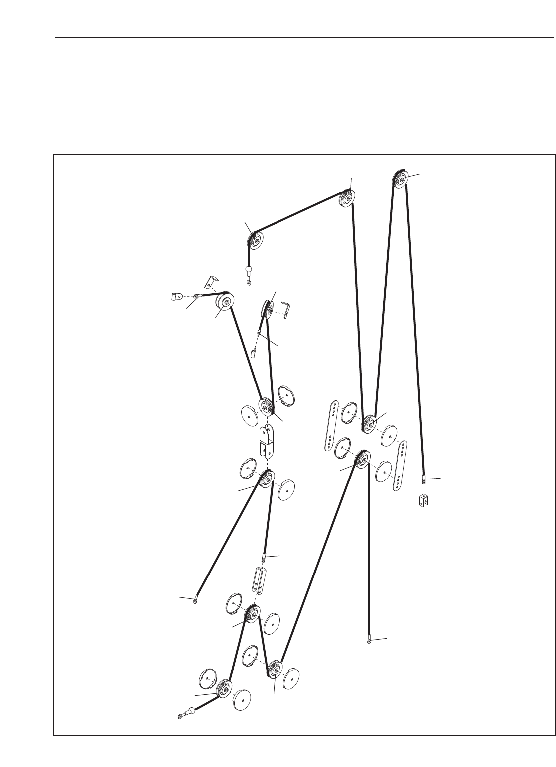
CABLE DIAGRAM
The cable diagram below shows the proper routing of the Butterfly Cable (55), the Low Cable (56), the High
Cable (57), and the Short Cable (94). Use the diagrams to make sure that the cables and the cable traps have
been assembled correctly. If the cables have not been correctly routed, the weight system will not function prop-
erly and damage may occur. The numbers show the correct route for each cable. Make sure that the cable
traps do not touch or bind the cables.
1
1
2
3
1
1
2
2
3
3
4
5
24
3
5
4
5
High Cable (57)
Length: 3.68m
Butterfly Cable (55)
Length: 1.34m
Short Cable (94)
Length: 1.44m Low Cable (56)
Length: 2.07m

21
EXERCISE GUIDELINES
THE FOUR BASIC TYPES OF WORKOUTS
MUSCLE BUILDING
To increase the size and strength of your muscles,
push them close to their maximum capacity. Your mus-
cles will continually adapt and grow as you progres-
sively increase the intensity of your exercise. You can
adjust the intensity level of an individual exercise in
two ways:
•by changing the amount of resistance used
•by changing the number of repetitions or sets per-
formed. (A “repetition” is one complete cycle of an
exercise, such as one sit-up. A “set” is a series of
repetitions.)
The proper amount of resistance for each exercise
depends upon the individual user. You must gauge
your limits and select the amount of resistance that is
right for you. Begin with 3 sets of 8 repetitions for each
exercise you perform. Rest for 3 minutes after each
set. When you can complete 3 sets of 12 repetitions
without difficulty, increase the amount of resistance.
TONING
You can tone your muscles by pushing them to a mod-
erate percentage of their capacity.Select a moderate
amount of resistance and increase the number of rep-
etitions in each set. Complete as many sets of 15 to
20 repetitions as possible without discomfort. Rest for
1minute after each set. Work your muscles by com-
pleting more sets rather than by using high amounts of
resistance.
WEIGHT LOSS
To lose weight, use a low amount of resistance and
increase the number of repetitions in each set.
Exercise for 20 to 30 minutes, resting for a maximum
of 30 seconds between sets.
CROSS TRAINING
Cross training is an efficient way to get a complete and
well-balanced fitness program. An example of a bal-
anced program is:
•Plan strength training workouts on Monday,
Wednesday,and Friday.
•Plan 20 to 30 minutes of aerobic exercise, such as
running on a treadmill or riding on an elliptical or
exercise bike, on Tuesday and Thursday.
•Rest from both strength training and aerobic exercise
for at least one full day each week to give your body
time to regenerate.
The combination of strength training and aerobic exer-
cise will reshape and strengthen your body, plus devel-
op your heart and lungs.
PERSONALISING YOUR EXERCISE PROGRAM
Determining the exact length of time for each workout,
as well as the number of repetitions or sets completed,
is an individual matter. It is important to avoid overdo-
ing it during the first few months of your exercise pro-
gram. You should progress at your own pace and be
sensitive to your body’s signals. If you experience pain
or dizziness at any time whilst exercising, stop imme-
diately and begin cooling down. Find out what is wrong
before continuing. Remember that adequate rest and a
proper diet are important factors in any exercise pro-
gram.
WARMING UP
Begin each workout with 5 to 10 minutes of stretching
and light exercise to warm up. Warming up prepares
your body for more strenuous exercise by increasing
circulation, raising your body temperature and deliver-
ing more oxygen to your muscles.
WORKING OUT
Each workout should include 6 to 10 different exercis-
es. Select exercises for every major muscle group,
emphasising areas that you want to develop most. To
give balance and variety to your workouts, vary the
exercises from session to session.
Schedule your workouts for the time of day when your
energy level is the highest. Each workout should be
followed by at least one day of rest. Once you find the
schedule that is right for you, stick with it.
EXERCISE FORM
Maintaining proper form is an essential part of an
effective exercise program. This requires moving
through the full range of motion for each exercise, and
moving only the appropriate parts of the body.
Exercising in an uncontrolled manner will leave you
feeling exhausted. On the exercise guide accompany-
ing this manual you will find photographs showing the
correct form for several exercises, and a list of the
muscles affected. Refer to the muscle chart on the
next page to find the names of the muscles.
The repetitions in each set should be performed
smoothly and without pausing. The exertion stage of
each repetition should last about half as long as the
return stage. Proper breathing is important. Exhale
during the exertion stage of each repetition and inhale
during the return stroke. Never hold your breath.
22
Rest for a short period of time after each set. The
ideal resting periods are:
•Rest for three minutes after each set for a muscle
building workout.
•Rest for one minute after each set for a toning work-
out.
•Rest for 30 seconds after each set for a weight loss
workout.
Plan to spend the first couple of weeks familiarising
yourself with the equipment and learning the proper
form for each exercise.
COOLING DOWN
End each workout with 5 to 10 minutes of stretching.
Include stretches for both your arms and legs. Move
slowly as you stretch and do not bounce. Ease into
each stretch gradually and go only as far as you can
without strain. Stretching at the end of each workout
is an effective way to increase flexibility.
STAYING MOTIVATED
For motivation, keep a record of each workout. The
chart on page 23 of this manual can be photocopied
and used to schedule and record your workouts. List
the date, the exercises performed, the resistance
used, and the numbers of sets and repetitions com-
pleted. Record your weight and key body measure-
ments at the end of every month. Remember, the key
to achieving the greatest results is to make exercise a
regular and enjoyable part of your everyday life.
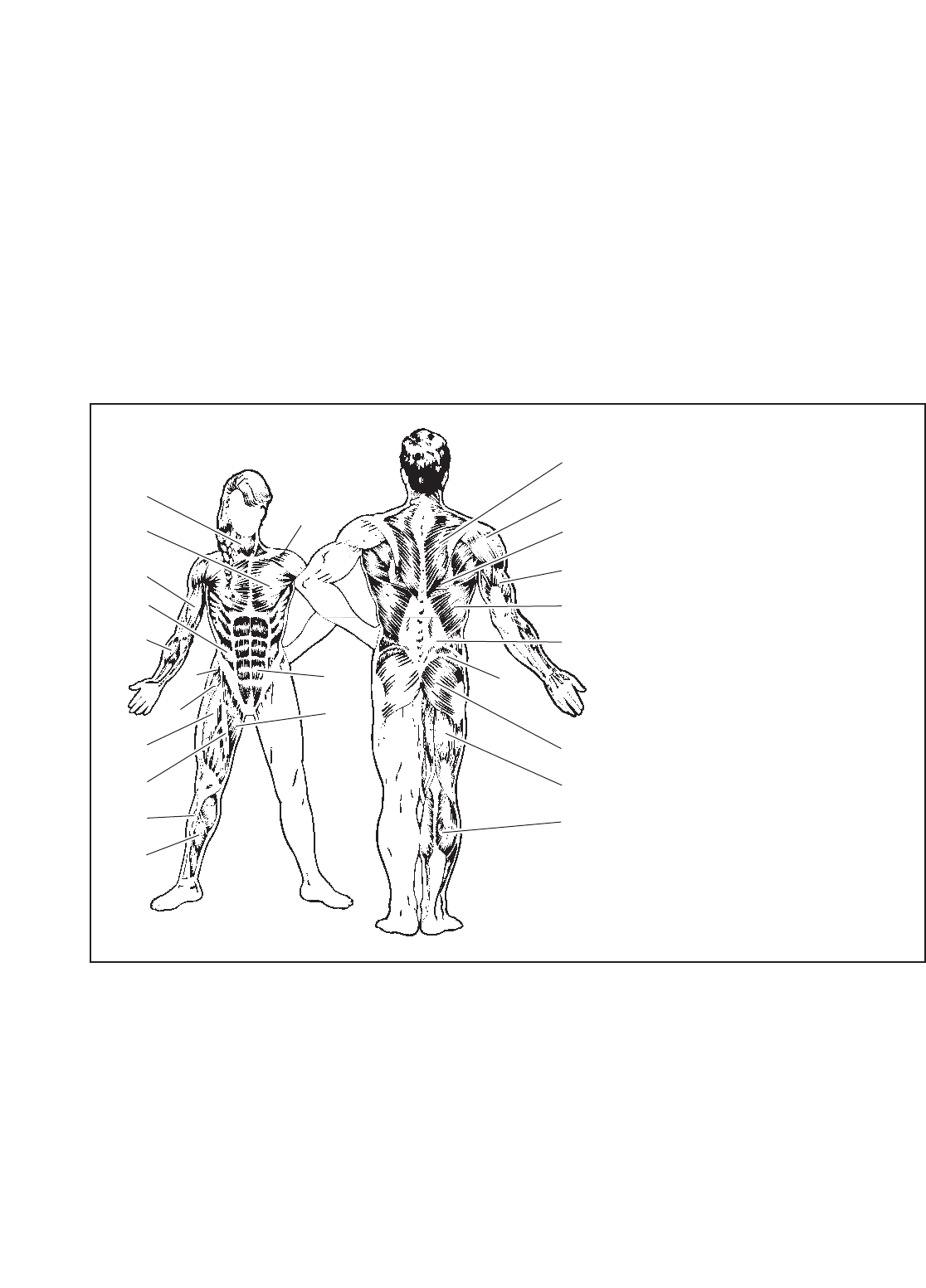
O
P
Q
R
S
T
U
V
X
W
N
M
J
G
F
H
I
K
E
C
D
B
A
L
MUSCLE CHART
A. Sternomastoid (neck)
B. Pectoralis Major (chest)
C. Biceps (front of arm)
D. Obliques (waist)
E. Brachioradials (forearm)
F. Hip Flexors (upper thigh)
G. Abductor (outer thigh)
H. Quadriceps (front of thigh)
I. Sartorius (front of thigh)
J. Tibialis Anterior (front of calf)
K. Soleus (front of calf)
L. Anterior Deltoid (shoulder)
M. Rectus Abdominus (stomach)
N. Adductor (inner thigh)
O. Trapezius (upper back)
P. Rhomboideus (upper back)
Q. Posterior Deltoid (shoulder)
R. Triceps (back of arm)
S. Latissimus Dorsi (mid back)
T. Spinae Erectors (lower back)
U. Gluteus Medius (hip)
V. Gluteus Maximus (buttocks)
W. Hamstring (back of leg)
X. Gastrocnemius (back of calf)

23
MONDAY
Date: / /
EXERCISE WEIGHT SETS REPS
EXERCISE WEIGHT SETS REPS
EXERCISE WEIGHT SETS REPS
AEROBIC EXERCISE
AEROBIC EXERCISE
TUESDAY
Date: / /
WEDNESDAY
Date: / /
THURSDAY
Date: / /
FRIDAY
Date: / /
Make photocopies of this page for scheduling and recording your workouts.

Part No. 203273 R1103A Printed in China © 2003 ICON Health & Fitness, Inc.
ORDERING REPLACEMENT PARTS
To order replacement parts, contact the ICON Health & Fitness, Ltd. office, or write:
ICON Health & Fitness, Ltd.
Unit 4
Revie Road Industrial Estate
Revie Road
Beeston
Leeds, LS118JG
UK
Tel:
Outside the UK: 0 (444) 113 387 7133
Fax: 0 (444) 113 387 7125
Please provide the following information when ordering replacement parts:
•the MODEL NUMBER of the product (WEEVSY20230)
•the NAME of the product (WEIDER®9025 weight system)
•the SERIAL NUMBER of the product (see the front cover of this manual)
• the KEY NUMBER and DESCRIPTION of the part(s) (see the PART LIST and EXPLODED DRAWING in the
centre of this manual)
08457 089 009
WEIDER is a registered trademark of ICON Health & Fitness, Inc.
81
REMOVE THIS PART LIST/EXPLODED DRAWING
FROM THE MANUAL.
SAVE THIS PART LIST/EXPLODED DRAWING FOR FUTURE REFERENCE
Note: Specifications are subject to change without notice. See the back cover
of the user’s manual for information about ordering replacement parts.

PART LIST—Model No. WEEVSY20230 R1103A
Note: “#” indicates a non-illustrated part. Specifications are subject to change without notice. See the back cover
of the user’smanual for information about ordering replacement parts.
1 1 Base
2 1 Stabiliser
3 1 Rear Upright
41 Front Upright
52 Weight Guide
6 1 Top Frame
7 1 Seat Frame
8 1 Leg Lever
9 1 Right Fly Arm
10 1 Left Fly Arm
11 1 Butterfly Frame
12 1 Right VKR Arm
13 1 Left VKR Arm
14 1 Right Pedal
15 1 Left Pedal
16 9 Weight
17 1 Weight Tube Bumper
18 1 Weight Tube
19 1 Top Weight
20 1 Weight Pin
21 1 Locking Bar
22 1 Lock
23 2 40mm x 50mm Inner Cap
24 2 Arm Handle
25 2 25mm Dome Inner Cap
26 2 Pad Tube
27 4 19mm Round Inner Cap
28 1 Seat Plate
29 5 38mm Square Inner Cap
30 2 25mm Round Outer Cap
31 3 50mm Square Inner Cap
32 2 Base Cap
33 1 Support Bracket
34 1 Grip Tape
35 4 38mm Square Bushing
36 2 Pedal Cover
37 2 Resistance Cylinder
38 2 16mm Round Outer Cap
39 2 16mm Retainer
40 2 16mm Round Bushing
41 4 Grip
42 2 VKR Handle
43 2 7mm Spacer
44 2 Weight Bumper
45 2 10mm Spacer
46 10 90mm Pulley
47 2 “V”-pulley
48 2 Cable Trap
49 14 Pulley Cover
50 2 Pulley Plate
51 1 Double “U”-bracket
52 1 Small “U”-bracket
53 1 “U”-bracket
54 6 12mm Spacer
55 1 Butterfly Cable
56 1 Low Cable
57 1 High Cable
58 2 Cable Pivot
59 4 Plastic Washer
60 4 Butterfly Cap
61 1 Backrest
62 1 Seat
63 1 VKR Back Pad
64 2 VKR Arm Pad
65 2 Large Foam Pad
66 4 Small Foam Pad
67 1 Handle
68 3 Cable Clip
69 10 M6 Washer
70 5 M6 x 53mm Screw
71 26 M10 Washer
72 33 M10 Nylon Locknut
73 8 M8 Nylon Locknut
74 9 M4 x 16mm Self-tapping Screw
75 8 M4 Washer
76 2 M6 x 16mm Screw
77 4 M6 x 65mm Screw
78 1 M6 x 50mm Carriage Bolt
79 1 M8 x 57mm Bolt
80 2 M10 x 55mm Bolt
81 2 M10 x 65mm Carriage Bolt
82 3 M8 x 67mm Carriage Bolt
83 1 M10 x 80mm Bolt
84 4 M8 x 20mm Button Head Bolt
85 2 M10 x 50mm Bolt
86 2 M10 x 83mm Button Head Bolt
87 9 M10 x 68mm Bolt
88 6 M10 x 53mm Bolt
89 4 M10 x 72mm Bolt
90 1 M6 Nylon Locknut
91 1 M10 x 153mm Bolt
92 1 M10 Star Washer
93 2 M8 x 20mm Shoulder Bolt
94 1 Short Cable
95 2 M10 x 60mm Bolt
96 1 M8 x 45mm Bolt
97 1 M10 x 63mm Eyebolt
98 2 25mm Retainer
99 1 Chain
100 2 “L”-pin
101 1 Lat Bar
102 2 Long Handgrip
103 1 50mm x 70mm Inner Cap
104 1 Ankle Strap
105 2 25mm Round Inner Cap
106 1 M8 Knob
107 1 M10 x 67mm Carriage Bolt
108 1 M10 Large Washer
109 2 18mm Spacer
# 1 User’s Manual
# 1 Exercise Guide
# 2 Grease Pack
Key No. Qty. Description Key No. Qty. Description
72
109
91
5
5
41
42
29
64
43
13
69
70 72
70
72
89
89
64
41
42
43
29
12
69
70
38
39
40
37
36
35
14
63
72
72
69
69
77
3
40
37
39
38
74
35
15
32
2
82
107
73
73
30
74
32
33
72
34
89
71
30
1
31
87
72 56
72
88
49
46
81
20
44
16
17
18
19
73
96
73
52
57
22
21
31
87
71
46 49
49
88
50
46
49
49
72 50
87
71
54
46
54
72
71 6
87
71
54
46
71
72
31
57
49
46
49
72 51
88
88
49
49
46
95
48
47
72
72
77
69
95
48
47
72
29
61
77
69
4
87
71
49
46 49
88
72 73
53
94
45
72
72
71
45
72
49
49
56
46
68
67
82
69
70
7
76
28
78
62
29
69
90
66
73 27
26
27
66
66
27
26
27 879
29 66
55
58
59
85
72
10
59
23
86
11
60
60
72
72
60
60
23
55
72
59
58
59
85
9
65
84
84
24
25
24
65
25
80
71
71
72
36
71
80
72
71
71
71
72
71 94
89
92
93
93
73
73
98
98
71
71
74
71
71
100
100
87
71
97
108
72
99
41
41
75
75
71 71
86
103
72
84 84
72
83
102
102
101
104
74
75
74
75
106
105
105
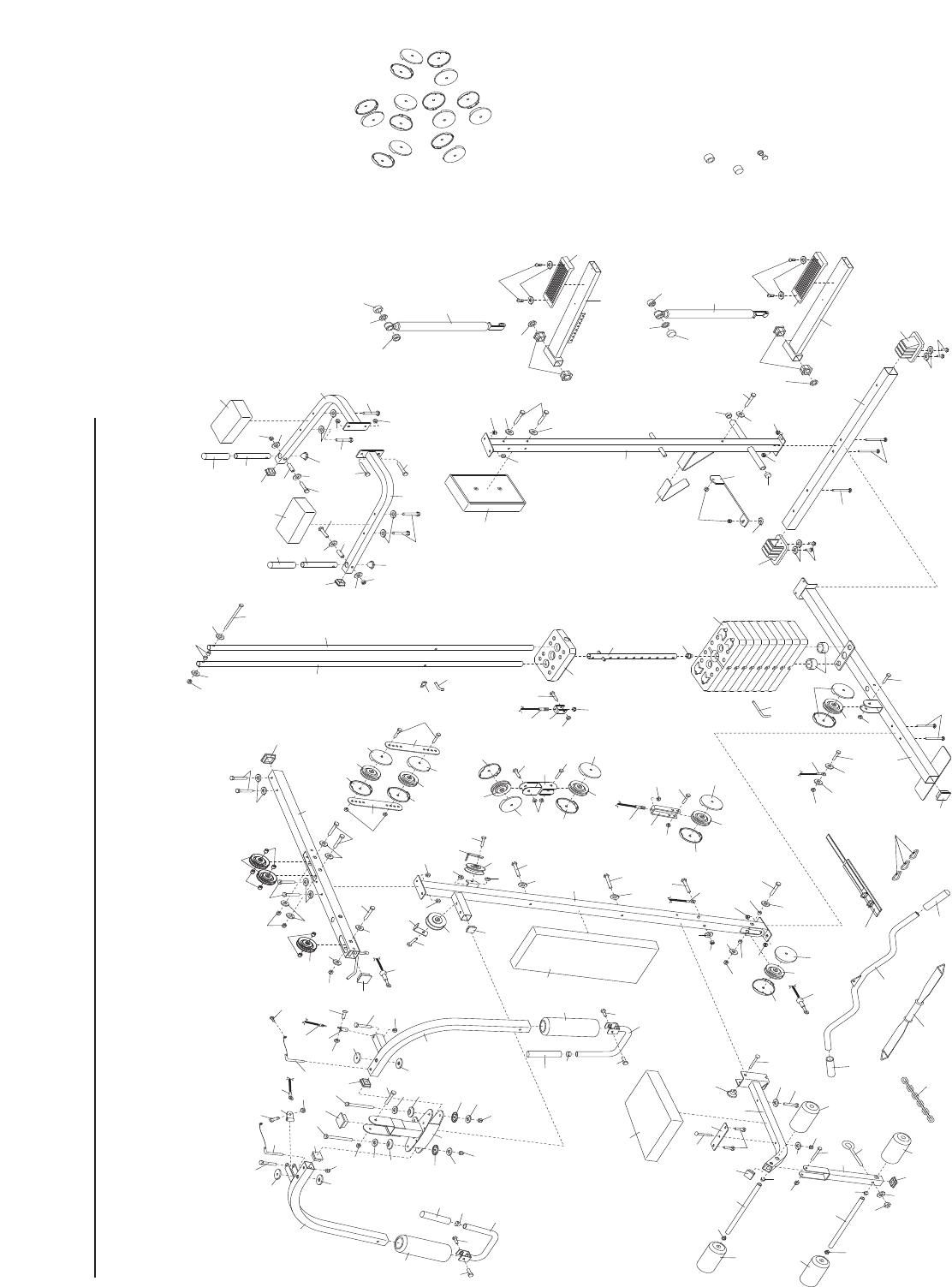
EXPLODED DRAWING—Model No. WEEVSY20230 R1103A
Note: Assembly is divided into four stages: 1) frame assembly, 2) arm
assembly,3) cable assembly,and 4) seat assembly.The hardware for
each stage is packaged separately. WAIT UNTIL YOU BEGIN EACH
ASSEMBLY STAGE TO OPEN THE PARTS BAG LABELLED FOR THAT
ASSEMBLY STAGE.
This chart is provided to help you identify the small parts used in assembly. The number in parenthesis below
each part refers to the key number of the part from the PART LIST in the centre of this manual. Important:
Some parts may have been pre-assembled for shipping purposes. If you cannot find a part in the parts
bags, check to see if it has been pre-assembled.
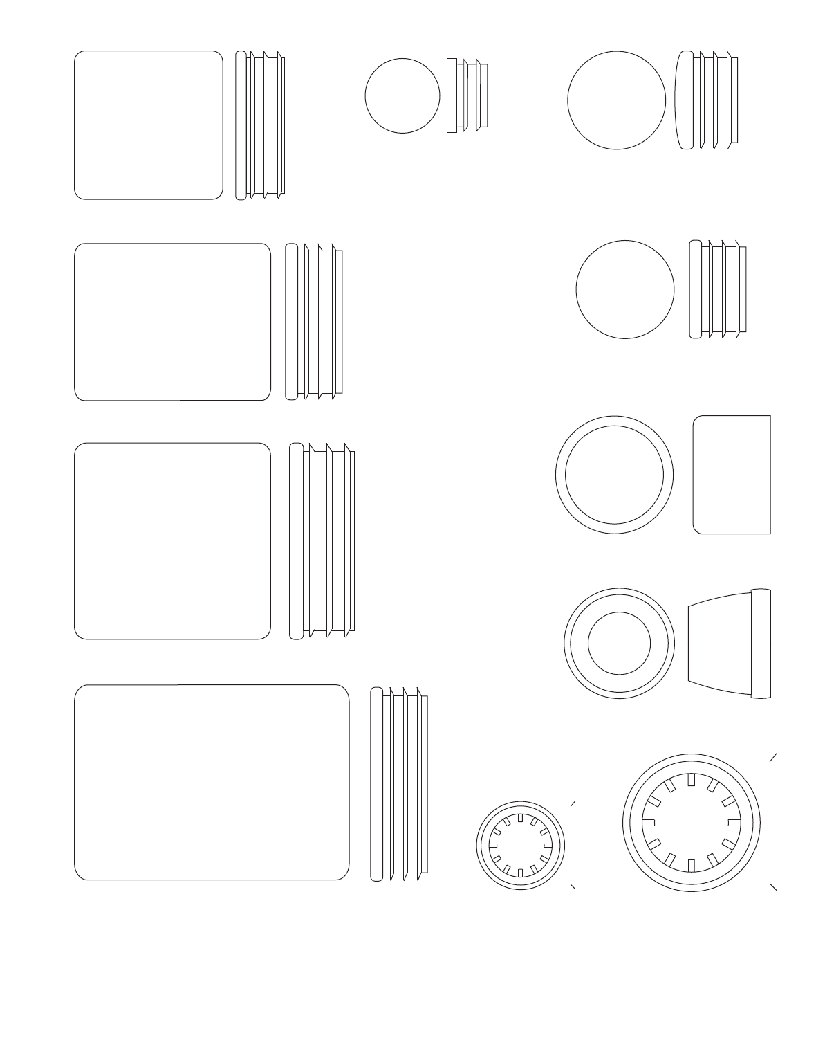
40mm x 50mm Inner Cap (23)
38mm Square Inner Cap (29)
50mm Square Inner Cap (31)
50mm x 70mm Inner Cap (103)
25mm Round Outer Cap (30)
25mm Retainer (98)
25mm Round Inner Cap (105)
19mm Round Inner Cap (27)
16mm Retainer (39)
16mm Round Outer Cap (38)
25mm Dome Inner Cap (25)
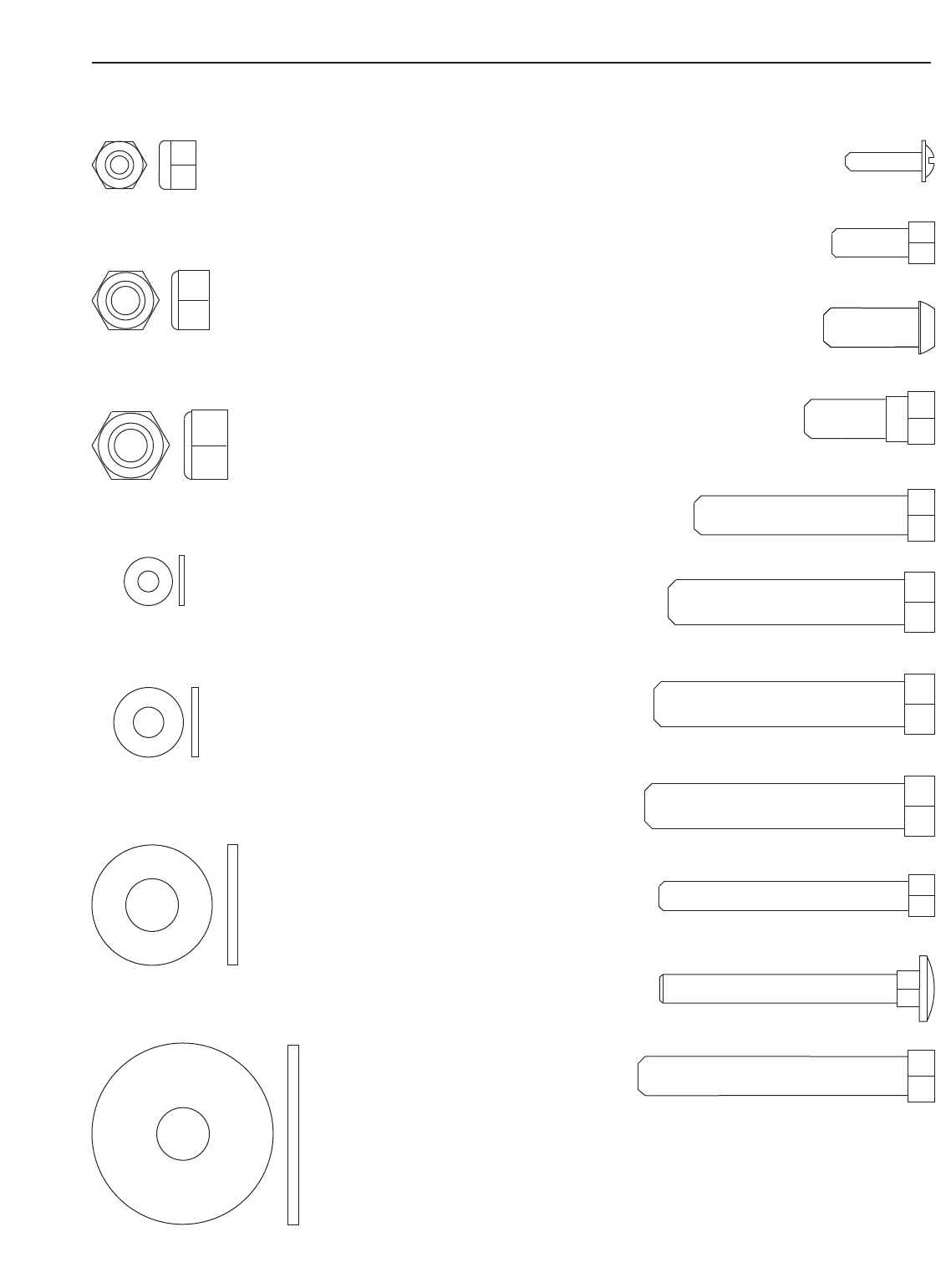
M10 Nylon Locknut (72)
M8 Nylon Locknut (73)
M6 Nylon Locknut (90)
M10 Large Washer (108)
M4 Washer (75)
M6 Washer (69)
M10 x 50mm Bolt (85)
M10 x 53mm Bolt (88)
M10 x 55mm Bolt (80)
M
M8 x 57mm Bolt (79)
M8 x 45mm Bolt (96)
M
M6 x 50mm Carriage Bolt (78)
M
M6 x 53mm Screw (70)
M6 x 16mm Screw (76)
M8 x 20mm Button Head Bolt (84)
M8 x 20mm Shoulder Bolt (93)
M4 x 16mm Self-tapping Screw (74)
M10 Washer (71)
PART IDENTIFICATION CHART
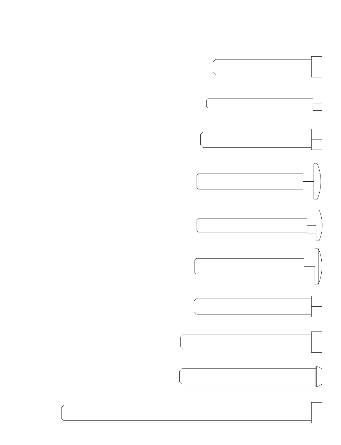
M10 x 60mm Bolt (95)
M10 x 80mm Bolt (83)
M10 x 68mm Bolt (87)
M10 x 72mm Bolt (89)
M10 x 153mm Bolt (91)
M10 x 83mm Button Head Bolt (86)
M10 x 67mm Carriage Bolt (107)
M10 x 65mm Carriage Bolt (81)
M8 x 67mm Carriage Bolt (82)
M
M6 x 65mm Screw (77)
