Weider Pro 3770 System Wesy3753 Users Manual
Weider-Wesy37531-Owner-S-Manual weider-wesy37531-owner-s-manual
Weider-Pro-3770-Wesy37531-Users-Manual-233728 weider-pro-3770-wesy37531-users-manual-233728
WESY37531 to the manual 0d93b8da-23d5-4d66-98ba-d33f1f705716
2015-05-18
: Weider Weider-Pro-3770-System-Wesy3753-Users-Manual-734065 weider-pro-3770-system-wesy3753-users-manual-734065 weider pdf
Open the PDF directly: View PDF ![]() .
.
Page Count: 33
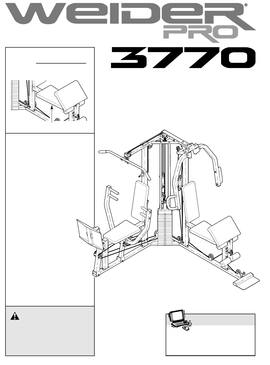
USER'S MANUAL
QUESTIONS?
As a manufacturer, we are
committed to providing complete
customer satisfaction. If you
have questions, or if there are
missing parts, we will guarantee
complete satisfaction through
assistance from our factory.
TO AVOID DELAYS, PLEASE
CALL DIRECT TO OUR TOLL-
FREE CUSTOMER HOT
LINE. The technicians on
our customer hot line
will provide immediate
assistance, free of
charge.
CUSTOMER HOT LINE:
1-800-999-3756
Mon.–Fri., 6 a.m.–6 p.m. MST
Model No. WESY37531
Serial No.
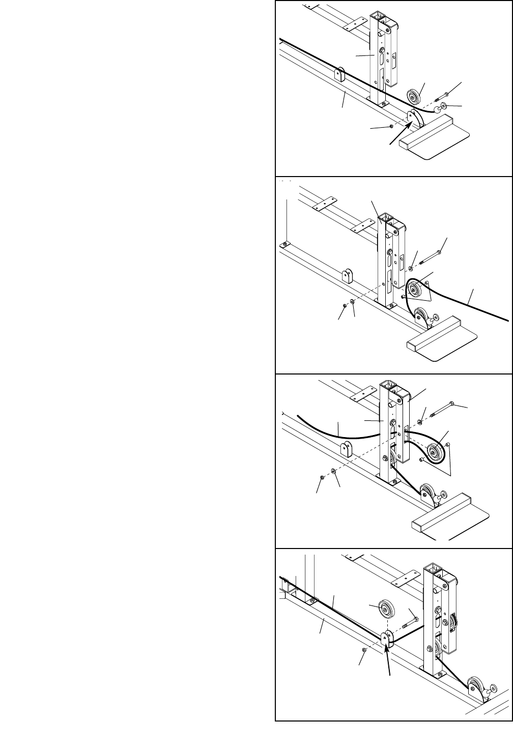
Write the serial number in the space
above for future reference.
CAUTION
Read all precautions and instruc-
tions in this manual before using
this equipment. Save this manual
for future reference.
Visit our website at
www.weiderfitness.com
new products, prizes,
fitness tips, and much more!
Serial Number Decal (Under Seat)

2
TABLE OF CONTENTS
IMPORTANT PRECAUTIONS . . . . . . . . . . . . . . . . . . . . . . . . . . . . . . . . . . . . . . . . . . . . . . . . . . . . . . . . . . . . .3
BEFORE YOU BEGIN . . . . . . . . . . . . . . . . . . . . . . . . . . . . . . . . . . . . . . . . . . . . . . . . . . . . . . . . . . . . . . . . . . .4
ASSEMBLY . . . . . . . . . . . . . . . . . . . . . . . . . . . . . . . . . . . . . . . . . . . . . . . . . . . . . . . . . . . . . . . . . . . . . . . . . . .5
ADJUSTMENTS . . . . . . . . . . . . . . . . . . . . . . . . . . . . . . . . . . . . . . . . . . . . . . . . . . . . . . . . . . . . . . . . . . . . . . .21
WEIGHT RESISTANCE CHART . . . . . . . . . . . . . . . . . . . . . . . . . . . . . . . . . . . . . . . . . . . . . . . . . . . . . . . . . . .23
TROUBLESHOOTING . . . . . . . . . . . . . . . . . . . . . . . . . . . . . . . . . . . . . . . . . . . . . . . . . . . . . . . . . . . . . . . . . .24
CABLE DIAGRAMS . . . . . . . . . . . . . . . . . . . . . . . . . . . . . . . . . . . . . . . . . . . . . . . . . . . . . . . . . . . . . . . . . . . .25
ORDERING REPLACEMENT PARTS . . . . . . . . . . . . . . . . . . . . . . . . . . . . . . . . . . . . . . . . . . . . . . . .Back Cover
LIMITED WARRANTY . . . . . . . . . . . . . . . . . . . . . . . . . . . . . . . . . . . . . . . . . . . . . . . . . . . . . . . . . . .Back Cover
Note: A PART IDENTIFICATION CHART and a PART LIST/EXPLODED DRAWING are attached in the center of
this manual. Remove the PART IDENTIFICATION CHART and the PART LIST/EXPLODED DRAWING before
beginning assembly.
WEIDER is a registered trademark of ICON Health & Fitness, Inc.
IMPORTANT PRECAUTIONS
3
1. Read all instructions in this manual and in
the accompanying literature before using the
weight system. Use the weight system only
as described in the literature.
2. It is the responsibility of the owner to ensure
that all users of the weight system are ade-
quately informed of all precautions.
3. The weight system is intended for home use
only. Do not use the weight system in any
commercial, rental, or institutional setting.
4. Use the weight system only on a level sur-
face. Cover the floor beneath the weight sys-
tem to protect the floor.
5. Make sure all parts are properly tightened
each time the weight system is used.
Replace any worn parts immediately.
6. Keep children under 12 and pets away from
the weight system at all times.
7. Keep hands and feet away from moving parts.
8. Always wear athletic shoes for foot protec-
tion.
9. Never release the press arm, butterfly arms,
leg lever, leg press, lat bar, ab strap, or nylon
strap while weights are raised. The weights
will fall with great force.
10. The weight system is designed to support a
a maximum user weight of 300 pounds.
11. Make sure that the cables remain on the pul-
leys at all times. If the cables bind while you
are exercising, stop immediately and make
sure that the cables are on all of the pulleys.
12. Always disconnect the lat bar from the
weight system when performing an exercise
that does not use the lat bar.
13. If you feel pain or dizziness at any time while
exercising, stop immediately and begin cool-
ing down.
14. The decal shown
here has been
placed on the weight
system in the loca-
tion shown on page
4. If the decal is
missing or illegible,
please call our
Customer Service
Department toll-free
at 1-800-999-3756,
Monday through
Friday, 6 a.m. until
6 p.m. Mountain
Time, to order a free
replacement decal.
Apply the decal in the location shown.
WARNING: To reduce the risk of serious injury, read the following important precautions
before using the weight system.
WARNING: Before beginning this or any exercise program, consult your physician. This
is especially important for persons over the age of 35 or persons with pre-existing health problems.
Read all instructions before using. ICON assumes no responsibility for personal injury or property
damage sustained by or through the use of this product.
4
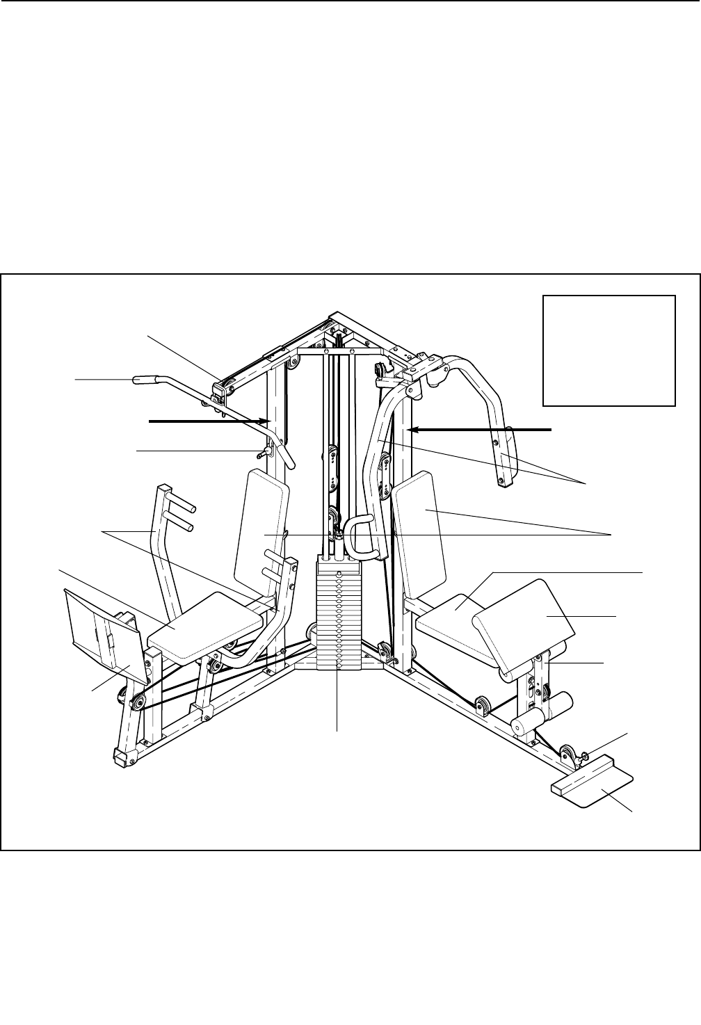
BEFORE YOU BEGIN
ASSEMBLED
DIMENSIONS:
Height: 76.0 in.
Width: 86.5 in.
Length: 91.5 in.
Foot Plate
Low Pulley
Station
High Pulley Station
Lat Bar
Leg Lever
Butterfly Arms
Press Arms
Leg Press
Seat Seat
Weight Stack
Backrests
Curl Pad
Ab Pulley Station
WARNING DECAL WARNING DECAL
Thank you for selecting the versatile WEIDER®PRO
3770 weight system. The weight system offers a selec-
tion of weight stations designed to develop every
major muscle group of the body. Whether your goal is
to tone your body, build dramatic muscle size and
strength, or improve your cardiovascular system, the
weight system will help you to achieve the specific
results you want.
For your benefit, read this manual carefully before
using the weight system. If you have additional
questions, please call our Customer Service
Department toll-free at 1-800-999-3756, Monday
through Friday, 6 a.m. until 6 p.m. Mountain Time
(excluding holidays). To help us assist you, please
note the product model number and serial number
before calling. The model number is WESY37531. The
serial number can be found on a decal attached to the
weight system (see the front cover of this manual).
Before reading further, please review the drawing
below and familiarize yourself with the parts that are
labeled.
5
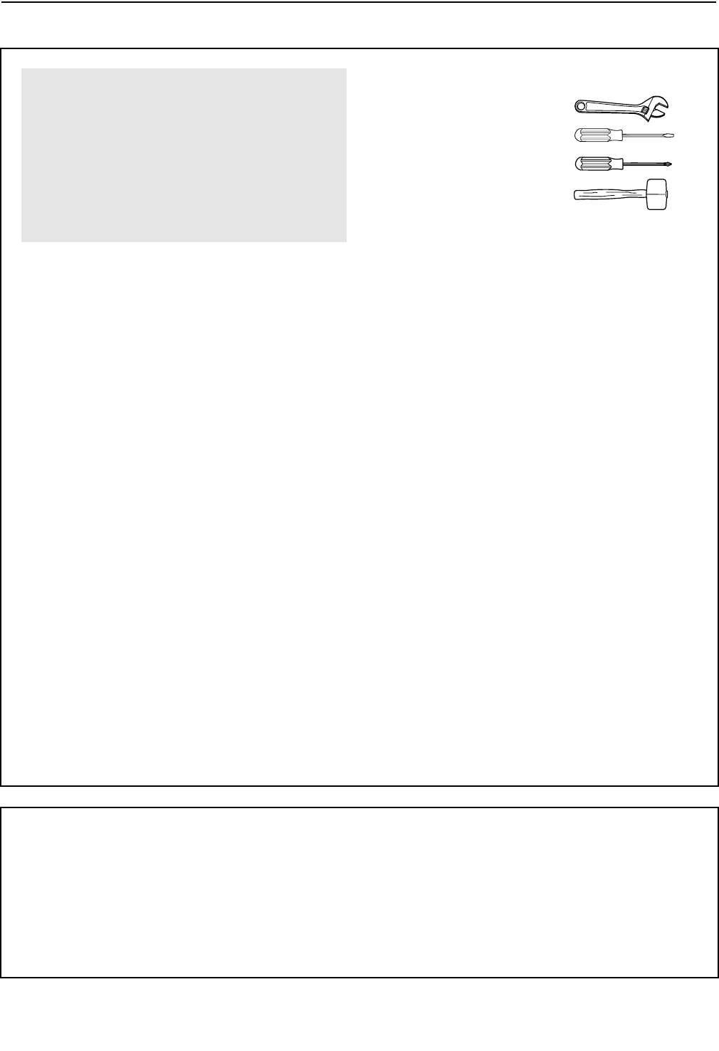
ASSEMBLY
Make sure you have the following tools:
• Two (2) adjustable wrenches
• One (1) standard screwdriver
• One (1) phillips screwdriver
• One (1) rubber mallet
• You will also need grease or petroleum jelly, a
small amount of soapy water, and clear tape or
masking tape.
Note: Assembly will be more convenient if you have
a socket set, a set of open-end or closed-end
wrenches, or a set of ratchet wrenches.
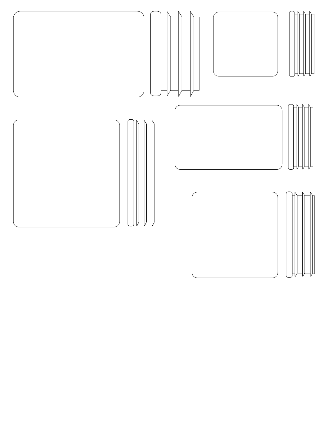
How to Identify Parts
To help you identify the small parts used in assembly,
we have included a PART IDENTIFICATION CHART
in the center of this manual. Place the chart on the
floor and use it to easily identify parts during each
assembly step. Note: Some small parts may have
been pre-attached. If a part is not in the parts
bag, check to see if it has been pre-attached.
How to Orient Parts
As you assemble the weight system, make sure that
all parts are oriented exactly as shown in the draw-
ings.
Tightening Parts
Tighten all parts as you assemble them, unless
instructed to do otherwise.
Questions?
If you have questions after reading the assembly
instructions, please call our Customer Service
Department toll-free at 1-800-999-3756, Monday
through Friday, 6 a.m. until 6 p.m. Mountain Time.
Assembly Requires Two Persons
For your convenience and safety, assemble the
weight system with the help of another person.
Set Aside Enough Time
Due to the many features of the weight system, the
assembly process will require about six hours. By
setting aside plenty of time and by deciding to
make the task enjoyable, assembly will go smoothly.
You may want to assemble the weight system over
a couple of evenings.
Select a Location for the Weight System
Because of its weight and size, the weight system
should be assembled in the location where it will be
used. Make sure that there is enough room to walk
around the weight system as you assemble it.
How to Unpack the Box
To make assembly as easy as possible, we have
divided the assembly process into four stages. The
parts needed for each stage are found in individual
bags. Important: Wait until you begin each stage
to open the parts bag for that stage. Place all
parts of the weight system in a cleared area and
remove the packing materials. Do not dispose of
the packing materials until assembly is completed.
Make Assembly Easier
Everything in this manual is designed to
ensure that the weight system can be assem-
bled successfully by anyone. Before begin-
ning assembly, make sure to read the
information on this page. This brief intro-
duction will save you much more time than
it takes to read it.
The Four Stages of the Assembly Process
Frame Assembly—You will begin by assembling
the base and the uprights that form the skeleton of
the weight system.
Arm Assembly—During this stage you will
assemble the arms and the leg levers.
Cable Assembly—During this stage you will
attach the cables and pulleys that connect the
arms to the weights.
Seat Assembly—During the final stage you will
assemble the seats and the backrest.
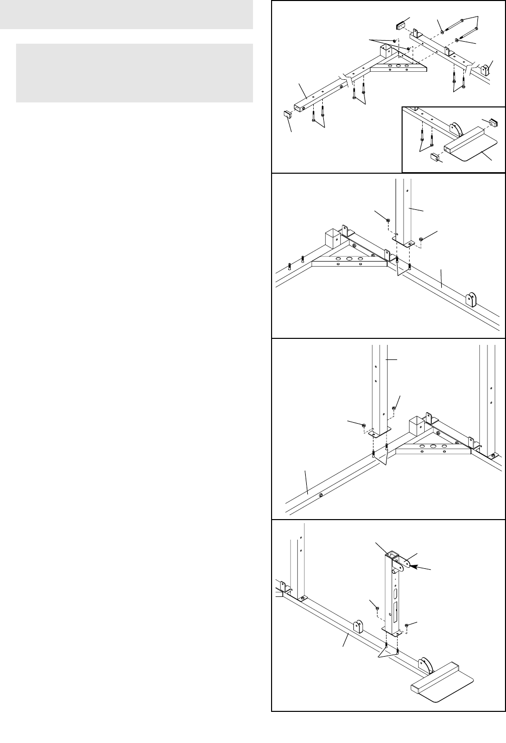
1.
Locate and open the parts bags labeled “FRAME
ASSEMBLY.”
See the inset drawing. Insert two 1 1/2” x 2 1/2”
Inner Caps (83) and two 3/8” x 2” Carriage Bolts
(92) into the Butterfly Base (4).
Insert two 1 1/2” x 2 1/2” Inner Caps (83) into the
indicated ends of the Butterfly Base (4) and the
Press Base (6). Insert six 3/8” x 2” Carriage Bolts
(92) into the Butterfly Base and the Press Base.
Attach the Butterfly Base (4) to the Press Base (6)
with two 3/8” x 3 1/4” Bolts (62), two 3/8” Flat
Washers (48), and two 3/8” Nylon Locknuts (50).
2
3
FRAME ASSEMBLY
6
50
50
1
4
50
6
50
2
Before you begin this step, make sure that
you have read all of the information on page
5. This brief introduction will save you much
more time than it takes to read it.
1
83
62
83 48
83
50
4
83 4
48
6
2. Attach the Butterfly Upright (1) to the indicated 3/8”
x 2” Carriage Bolts (92) on the Butterfly Base (4)
with two 3/8” Nylon Locknuts (50). Do not tighten
the Nylon Locknuts yet.
3. Attach the Press Upright (2) to the indicated 3/8” x
2” Carriage Bolts (92) on the Press Base (6) with
two 3/8” Nylon Locknuts (50). Do not tighten the
Nylon Locknuts yet.
4. Make sure the Plastic Bushing (52) is in the top of
the Butterfly Front Leg (3).
Attach the Butterfly Front Leg (3) to the indicated
3/8” x 2” Carriage Bolts (92) on the Butterfly Base
(4) with two 3/8” Nylon Locknuts (50). Do not tight-
en the Nylon Locknuts yet. Make sure that the
Butterfly Front Leg is turned so that the U-
Bracket is on the side shown.
92
4
50
3
U-Bracket
50
52
4
92
92
92
92
92
92
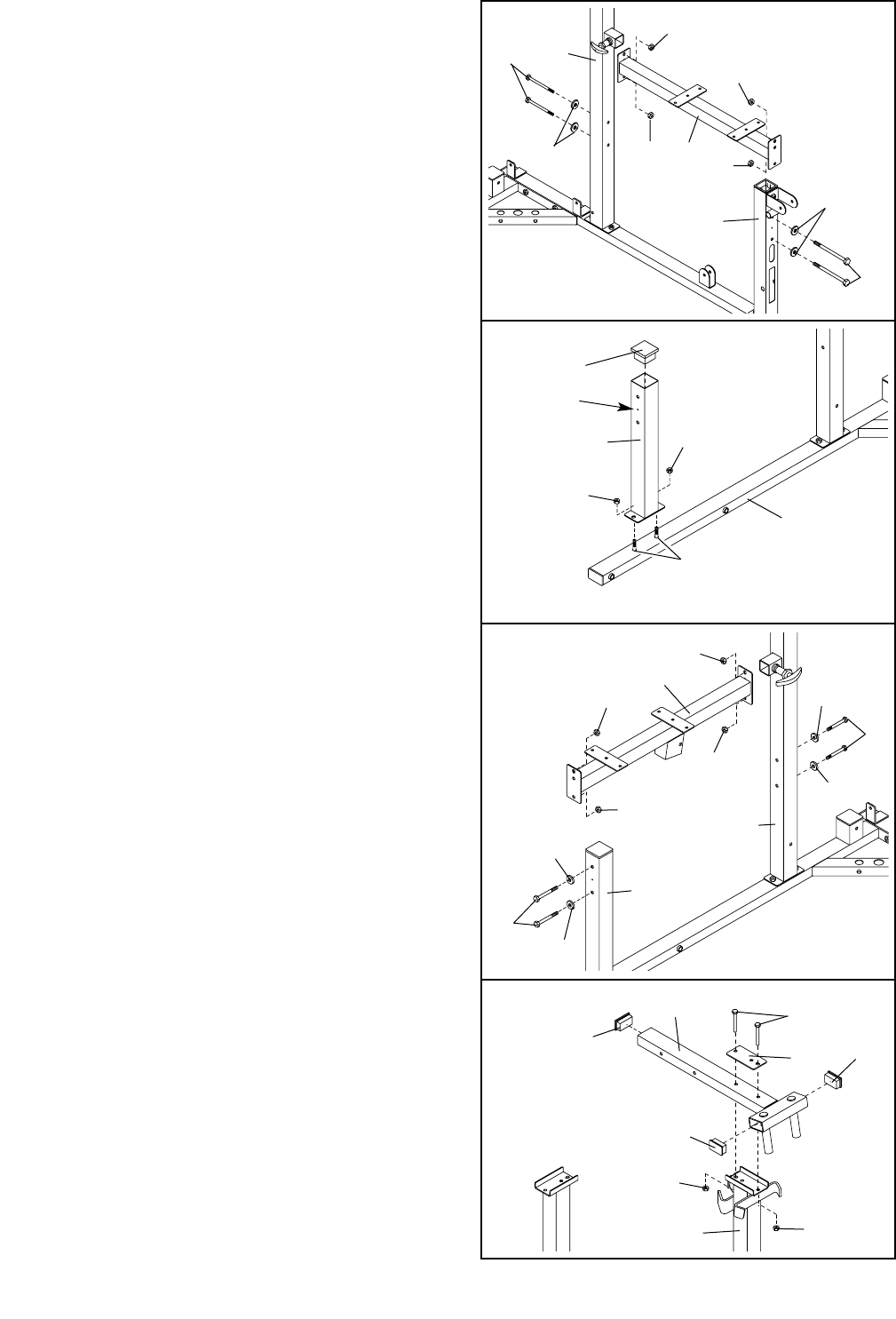
5. Attach the Butterfly Seat Frame (14) to the Butterfly
Upright (1) with two 3/8” x 3 1/4” Bolts (62), two 3/8”
Flat Washers (48), and two 3/8” Nylon Locknuts
(50).
Attach the Butterfly Seat Frame (14) to the Butterfly
Front Leg (3) with two 3/8” x 3 1/4” Bolts (62), two
3/8” Flat Washers (48) and two 3/8” Nylon Locknuts
(50).
Do not tighten the Nylon Locknuts (50) yet.
6. Press a 2 1/2” Square Inner Cap (76) into the Press
Front Leg (20).
Attach the Press Front Leg (20) to the indicated
3/8” x 2” Carriage Bolts (92) on the Press Base (6)
with two 3/8” Nylon Locknuts (50). Do not tighten
the Nylon Locknuts yet. Make sure that the
Press Front Leg is turned so that the indicated
hole is on the side shown.
7. Attach the Press Seat Frame (7) to the Press
Upright (2) with two 3/8” x 3 1/4” Bolts (62), two 3/8”
Flat Washers (48), and two 3/8” Nylon Locknuts
(50).
Attach the Press Seat Frame (7) to the Press Front
Leg (20) with two 3/8” x 3 1/4” Bolts (62), two 3/8”
Flat Washers (48), and two 3/8” Nylon Locknuts
(50).
Do not tighten the Nylon Locknuts (50) yet.
6
7
76
50
50
6
20
Hole
5
3
1
62
50
62
50
14
50
48
50
48
7
50
20
7
2
48
48
48
48
62
50
50
62
50
8
83
87
94
33
83
50
150
8. Insert three 1 1/2” x 2 1/2” Inner Caps (83) into the
ends of the Butterfly Top Frame (33).
Attach the Butterfly Top Frame (33) to the Butterfly
Upright (1) with two 3/8” x 2 1/2” Bolts (87), a
Support Plate (94), and two 3/8” Nylon Locknuts
(50). Do not tighten the Nylon Locknuts yet.
83
92
8
89
48 48
48
89
51
650
48
21
Slot
15
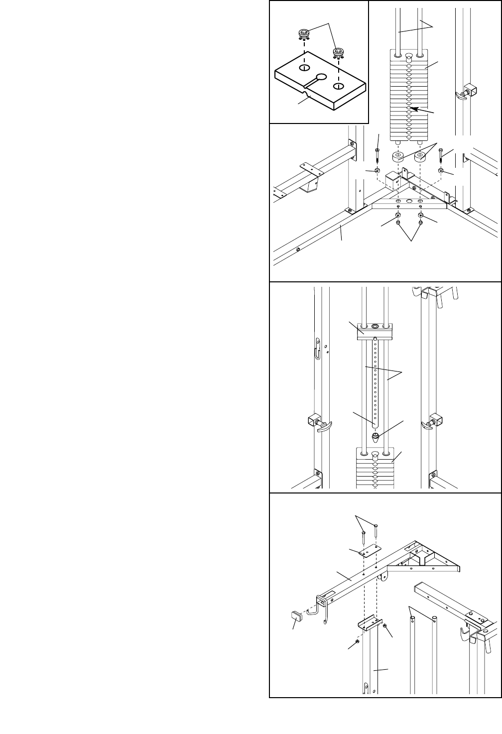
9. See the inset drawing. Insert two Weight Inserts
(56) into each Weight (21).
Set the two Weight Bumpers (51) over the holes in
the corner bar of the Press Base (6).
Slide the Weight Guides (15) through the Weight
Bumpers (51) and the holes in the Press Base (6).
Secure the Weight Guides to the Press Base with
two 3/8” x 2 3/4” Bolts (89), four 3/8” Flat Washers
(48), and two 3/8” Nylon Locknuts (50).
Slide the Weights (21) onto the Weight Guides (15),
stacking them on top of the Weight Bumpers (51).
Note: Be sure the Weights are oriented so that
the slots in the Weights are toward the front, as
shown.
10. Press the Weight Tube Bumper (18) into the Weight
Tube (17).
Slide the Top Weight (16) onto the Weight Guides
(15), so that the Weight Tube (17) goes into the
center hole in the Weights (21).
10
15
21
18
16
17
21
56
9
11
83
2
9
87
94
50 50
15
11. Press a 1 1/2” x 2 1/2” Inner Cap (83) into the end
of the Press Top Frame (9).
Attach the Press Top Frame (9) and a Support
Plate (94) to the Press Upright (2) with two 3/8” x
2 1/2” Bolts (87) and two 3/8” Nylon Locknuts (50).
Do not tighten the Nylon Locknuts yet.
Note: Be sure that the Weight Guides (15) are
properly positioned in relation to the Press Top
Frame (9), as shown in drawing 12 on the next
page.
9
48 62
50
48
33
9
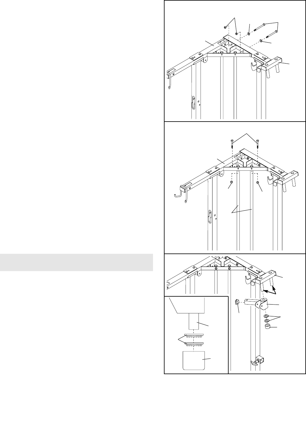
12. Secure the Press Top Frame (9) to the Butterfly Top
Frame (33) with two 3/8” x 3 1/4” Bolts (62), two
3/8” Flat Washers (48), and two 3/8” Nylon
Locknuts (50). Do not tighten the Nylon Locknuts
yet.
13. Secure the Weight Guides (15) to the Press Top
Frame (9) with two 3/8” x 1 3/4” Bolts (57) and two
3/8” Nylon Locknuts (50).
Tighten the Nylon Locknuts (50) used in steps
2–13.
12
13 57
9
50
50
15
14
85
35
Lubricate
31
33
38
Axle
31
38
14. Locate and open the parts bag labeled “ARM
ASSEMBLY.”
Press a 1 1/2” Square Inner Cap (35) into the Right
Pivot Arm (85).
Lubricate the axles on the Butterfly Top Frame (33).
Secure the Right Pivot Arm (85) to the right axle
with two Retainer Rings (31) and a 1” Round Outer
Cap (38). Do not confuse the Right Pivot Arm
with the Left Pivot Arm (not shown). The
Retainer Rings may break if disassembled.
Note: Be sure the Retainer Rings (31) and 1”
Round Outer Cap (38) are oriented as shown in
the inset drawing.
Repeat this step with the Left Pivot Arm (not
shown) and left axle.
ARM ASSEMBLY
10
15
48
48
10
84
28
10
28
48
48
53
53
15. Insert a 2” Square Inner Cap (28) into the end of
the Butterfly Arm (10).
Attach a Butterfly Handle (53) to the Butterfly Arm
(10) with two 3/8” x 1” Bolts (84) and two 3/8” Flat
Washers (48).
Repeat this step with the other Butterfly Arm (10).
16. Lubricate a 3/8” x 3 1/4” Bolt (62). Attach the left
Butterfly Arm (10) to the Left Pivot Arm (71) with
the Bolt and a 3/8” Nylon Locknut (50).
Repeat this step with the right Butterfly Arm (not
shown) and the Right Pivot Arm (85).
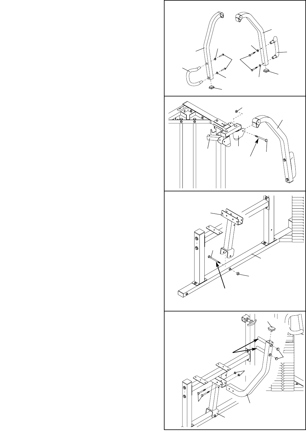
18. Insert a 2” Square Inner Cap (28) into the top of a
Press Arm (77). Press two 1” Round Inner Caps
(86) into the outside ends of the handles.
Attach the Press Arm (77) to the Press Frame (8)
with two 5/16” x 2 3/4” Bolts (96) and two 5/16”
Nylon Locknuts (64).
Repeat this step with the other Press Arm (77).
16 50
10
71
85 62
Lubricate
18
77
64
96
8
28
86
Handles
17. Lubricate a 1/2” x 4” Bolt (68). Attach the Press
Frame (8) to the Press Base (6) with the Bolt and a
1/2” Nylon Jamnut (36). Note: Do not over tighten
the 1/2” Nylon Jamnut (36); the Press Frame (8)
must be able to pivot easily.
17
8
36
6
68
Lubricate
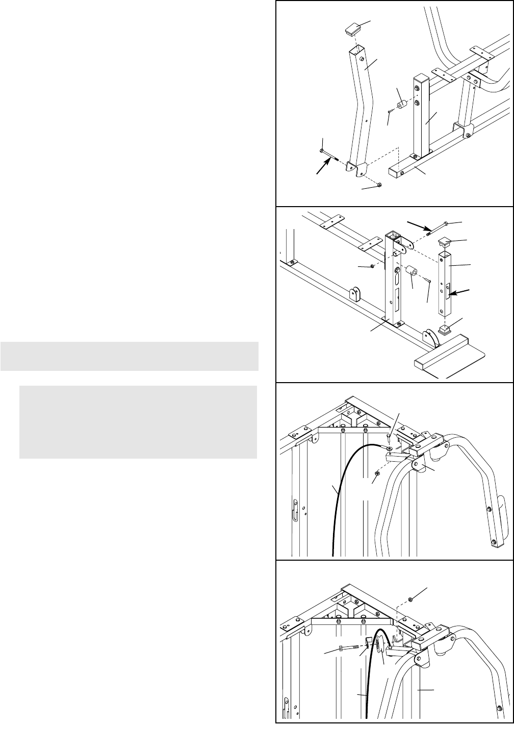
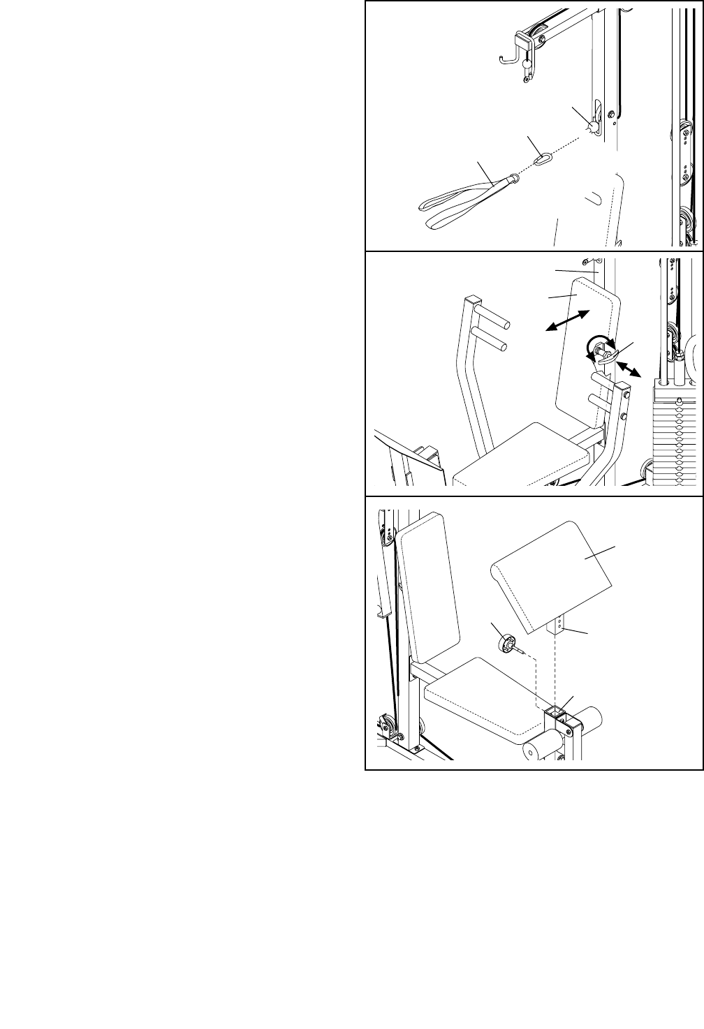
21.
Locate and open the parts bags labeled “CABLE
ASSEMBLY” and “PULLEYS.”
Locate the Butterfly Cable (73), which is the
shorter cable of the two that have eyelets on
both ends. Attach the Butterfly Cable (73) to the
Right Pivot Arm (85) with a 5/16” x 2 1/4” Shoulder
Bolt (79) and a 5/16” Nylon Jamnut (34).
11
19. Attach a Bumper (40) to the Press Front Leg (20)
with a 1” Tap Screw (80).
Press a 2” x 3” Inner Cap (78) into the top of the
Press Leg Lever (90).
Lubricate a 1/2” x 4” Bolt (68). Attach the Press Leg
Lever (90) to the Press Base (6) with the Bolt and a
1/2” Nylon Jamnut (36). Note: Do not over tighten
the Nylon Jamnut; the Press Leg Lever must be
able to pivot easily.
20. Insert two 2” Square Inner Caps (28) into the Leg
Lever (41).
Attach a Bumper (40) to the Butterfly Front Leg (3)
with a 1” Tap Screw (80).
Lubricate a 3/8” x 3” Bolt (88). Attach the Leg Lever
(41), with the small slot on the side shown, to the
Butterfly Front Leg (3) with the Bolt and a 3/8”
Nylon Jamnut (63). Note: Do not over tighten the
Nylon Jamnut; the Leg Lever must pivot easily.
22. Wrap the Butterfly Cable (73) over a “V”-Pulley
(27). Attach the “V”-Pulley and a Large Cable Trap
(32) to the bracket on the Butterfly Upright (1) with
a 3/8” x 2 1/2” Bolt (87) and a 3/8” Nylon Locknut
(50).
19
36
68
20
80
6
78
40
90
CABLE ASSEMBLY
20
21
22
41
Small
Slot
28
28
88
63
Lubricate
Lubricate
3
40
80
34
73
79
85
50
73
27
1
32
87
IMPORTANT: While assembling the cables, do
not over tighten the bolts and nuts attaching
the pulleys. The pulleys must be able to turn
freely. Refer to the Cable ID Chart on page 26
for help identifying the cables.
12
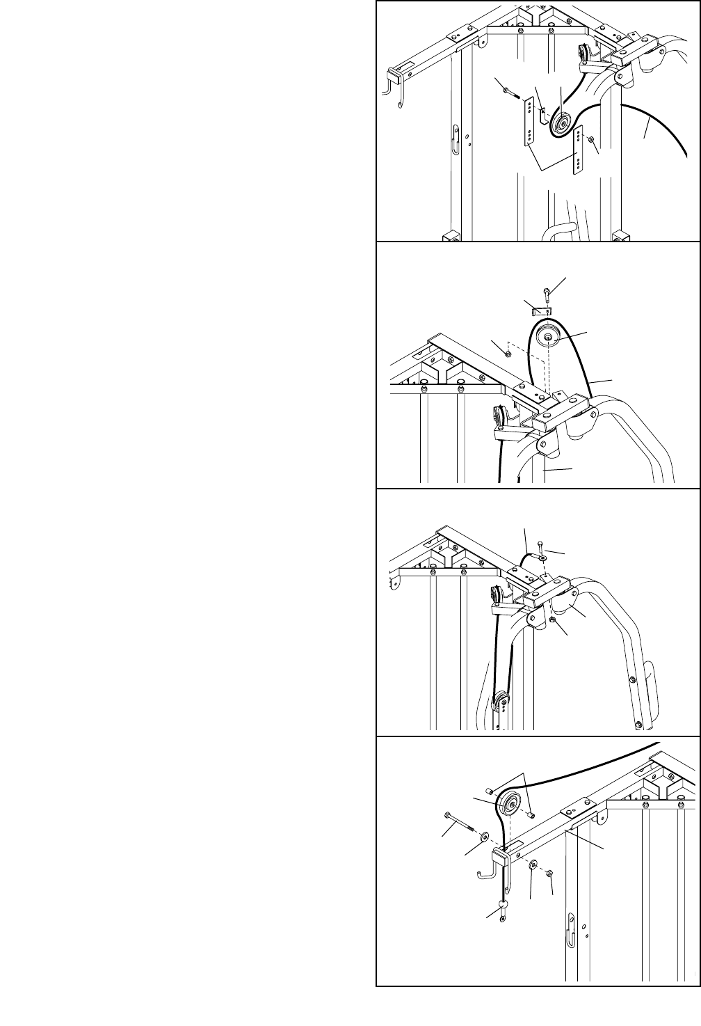
23. Remove the preassembled 3/8” x 2” Bolts (54) from
one set of Adjustable Pulley Plates (23).
Wrap the Butterfly Cable (73) around a 3 1/2”
Pulley (24). Attach the 3 1/2” Pulley and a Cable
Trap (25) between the top holes of the Adjustable
Pulley Plates (23) with a 3/8” x 2” Bolt (54) and a
3/8” Nylon Locknut (50). Be sure that the Cable
Trap is turned to hold the Cable in place.
24. Wrap the Butterfly Cable (73) around a “V”-Pulley
(27). Attach the “V”-Pulley and a Large Cable Trap
(32) to the bracket on the Butterfly Upright (1) with
a 3/8” x 2 1/2” Bolt (87) and a 3/8” Nylon Locknut
(50). Be sure that the Cable Trap is turned to
hold the Cable in place.
25. Attach the Butterfly Cable (73) to the Left Pivot Arm
(71) with a 5/16” x 2 1/4” Shoulder Bolt (79) and a
5/16” Nylon Jamnut (34).
26. Locate the Ab Cable (47). Insert the Ab Cable up
through the Press Top Frame (9) and wrap it
around a 3 1/2” Pulley (24). Attach a 3/8” Flat
Washer (48) and a 5/8” x 3/4” Bushing (66) to a
3/8” x 3 1/4” Bolt (62). Slide the Bolt through the
Press Top Frame and the 3 1/2” Pulley. Secure
another 5/8” x 3/4” Bushing and 3/8” Flat Washer to
the Bolt with a 3/8” Nylon Locknut (50).
26
23
24
25
48
48 9
50
50 27
73
71
79
34
54 25 24
50 73
23
87
32
73
1
47
24
66
62
13
27. Wrap the Ab Cable (47) around a 3 1/2” Pulley (24).
Insert the Ab Cable down through the Press Top
Frame (9). Attach a 3/8” Flat Washer (48) and a
5/8” x 3/4” Bushing (66) to a 3/8” x 3 1/4” Bolt (62).
Slide the Bolt through the Press Top Frame and the
3 1/2” Pulley. Secure another 5/8” x 3/4” Bushing
and 3/8” Flat Washer to the Bolt with a 3/8” Nylon
Locknut (50).
28. Remove the preassembled 3/8” x 2” Bolts (54) from
the other Adjustable Pulley Plates (23).
Wrap the Ab Cable (47) around a 3 1/2” Pulley (24).
Attach the 3 1/2” Pulley and a Cable Trap (25)
between the top holes in the Adjustable Pulley
Plates (23) with a 3/8” x 2” Bolt (54) and a 3/8”
Nylon Locknut (50). Be sure that the Cable Trap
is turned to hold the Cable in place.
29. Wrap the Ab Cable (47) around a 3 1/2” Pulley (24).
Attach the 3 1/2” Pulley to the rear bracket on the
Press Top Frame (9) with a 3/8” x 2” Bolt (54) and a
3/8” Nylon Locknut (50). Be sure the Ab Cable is
routed in the direction shown.
Wrap the Ab Pulley (47) around another 3 1/2”
Pulley (24). Attach the 3 1/2” Pulley to the forward
bracket on the Press Top Frame (9) with a 3/8” x 2”
Bolt (54) and a 3/8” Nylon Locknut (50).
30. Wrap the Ab Cable (47) around a 3 1/2” Pulley (24)
and slide the Ab Cable through the hole in the
Press Upright (2). Attach a 3/8” Flat Washer (48)
and a 5/8” x 3/4” Bushing (66) to a 3/8” x 3 1/4” Bolt
(62). Slide the Bolt through the Press Upright and
the 3 1/2” Pulley. Secure another 5/8” x 3/4”
Bushing and 3/8” Flat Washer to the Bolt with a 3/8”
Nylon Locknut (50).
30
27
28
29
66
48
50
48
62 24
47
9
47
23
54 24
82
50
9
Bracket
48
2
24
47
24
54
54
50
25
62 66
48
50
47
24
66
14
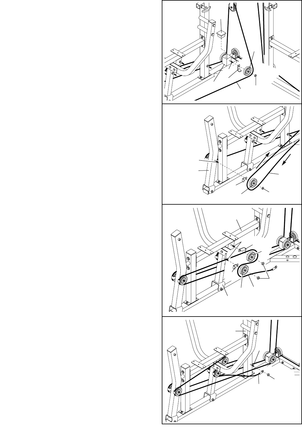
31. Locate the Weight Cable (72). Note that one end
of the Weight Cable has a bolt, and the other
end has a ball on it.
Lay the Weight Cable (72) inside the bracket on the
Butterfly Base (4) in the manner shown. Attach a
3 1/2” Pulley (24) to the bracket with a 3/8” x 2” Bolt
(54) and a 3/8” Nylon Locknut (50). Be sure the
Weight Cable is in the groove of the 3 1/2”
Pulley.
32. Wrap the Weight Cable (72) around a 3 1/2” Pulley
(24). Attach a 3/8” Flat Washer (48) and a 5/8” x
3/4” Bushing (66) to a 3/8” x 3 1/4” Bolt (62). Slide
the Bolt through the Butterfly Front Leg (3) and the
3 1/2” Pulley. Secure another 5/8” x 3/4” Bushing
and 3/8” Flat Washer to the Bolt with a 3/8” Nylon
Locknut (50).
33. Insert the Weight Cable (72) through the hole in the
Leg Lever (41), up around a 3 1/2” Pulley (24),
back through the hole in the Leg Lever, and through
the upper hole in the Butterfly Front Leg (3).
Attach the 3 1/2” Pulley (24) and two 5/8” x 1/2”
Bushings (93) to the Leg Lever (41) with a 3/8” x
2 3/4” Bolt (89), two 3/8” Flat Washers (48), and a
3/8” Nylon Locknut (50).
34. Lay the Weight Cable (72) under a 3 1/2” Pulley
(24) as shown. Attach the 3 1/2” Pulley to the
bracket on the Butterfly Base (4) with a 3/8” x 2”
Bolt (54) and a 3/8” Nylon Locknut (50).
31
32
33
34
72
4
50 Bracket
24 54
4
50
24
72
54
Bracket
48
72
50
3
62
48
66
24
48
41
24
93
48
50
72 389
3
15
36
37
38
35. Wrap the Weight Cable (72) around a 3 1/2” Pulley
(24). Attach the 3 1/2” Pulley and a Cable Trap (25)
to the Butterfly Upright (1) with a 3/8” x 4” Bolt (59),
a 3/8” Flat Washer (48), and a 3/8” Nylon Jamnut
(63). Be sure that the Cable Trap is turned to
hold the Cable in place.
36. Wrap the Weight Cable (72) around a 3 1/2” Pulley
(24). Attach the 3 1/2” Pulley and a Cable Trap (25)
between the lowest holes of the Adjustable Pulley
Plates (23) hanging from the Butterfly Cable (73)
with a 3/8” x 2” Bolt (54) and a 3/8” Nylon Locknut
(50) that was removed in step 23. Be sure that the
Cable Trap is turned to hold the Cable in place.
37. Wrap the Weight Cable (72) around a 3 1/2” Pulley
(24). Attach the 3 1/2” Pulley and a Cable Trap (25)
to the bracket on the Butterfly Base (4) with a 3/8” x
1 3/4” Bolt (57) and a 3/8” Nylon Jamnut (63). Be
sure that the Cable Trap is turned to hold the
Cable in place.
38. Note: For convenience, the weights assembled
in step 9 are not shown in the following draw-
ings.
Wrap the Weight Cable (72) around a 3 1/2” Pulley
(24). Attach the 3 1/2” Pulley and a Cable Trap (25)
to the bracket on the Butterfly Base (4) with a 3/8” x
1 3/4” Bolt (57) and a 3/8” Nylon Jamnut (63). Be
sure that the Cable Trap is turned to hold the
Cable in place.
35 1
72
59
63 48
25 24
24
72
54
73
Bracket
63
72
4
57
24
25
63
72
25
Bracket
24
25 50
4
57
23
16
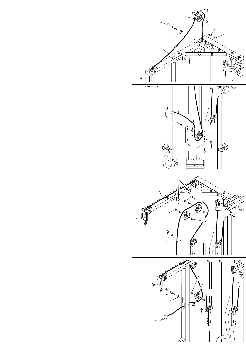
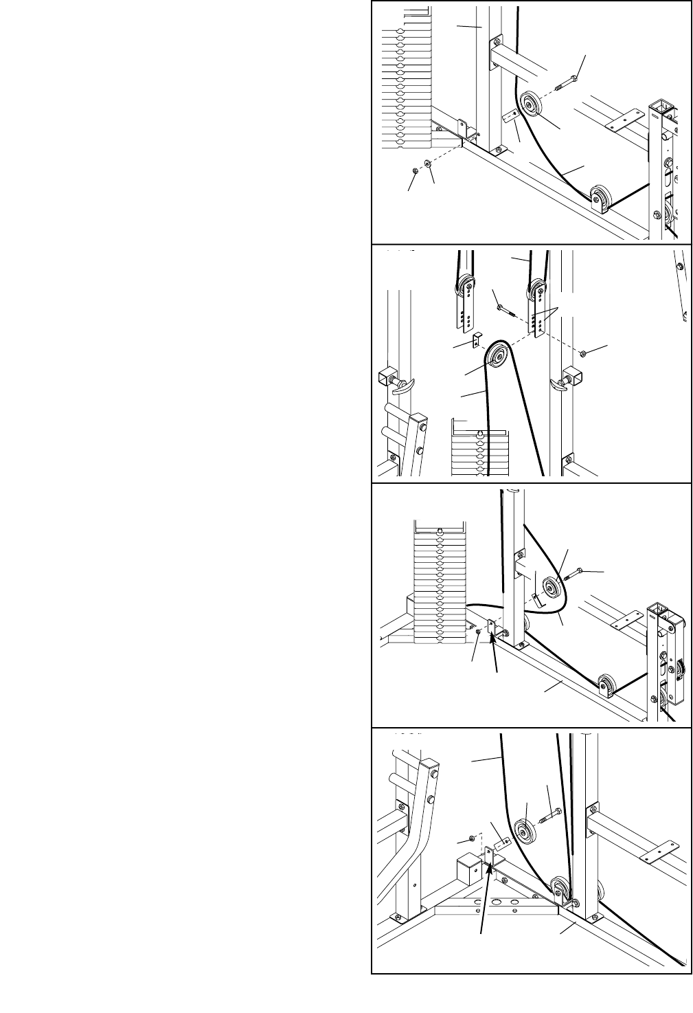
39. Wrap the Weight Cable (72) around a 3 1/2” Pulley
(24). Attach the 3 1/2” Pulley and a Cable Trap (25)
between the lowest holes in the Adjustable Pulley
Plates (23) hanging from the Ab Cable (47) with a
3/8” x 2” Bolt (54) and a 3/8” Nylon Locknut (50)
that was removed in step 28. Be sure that the
Cable Trap is turned to hold the Cable in place.
40. Remove the preassembled 3/8” x 1 3/4” Bolts (57)
from the Small Pulley Plates (22).
Wrap the Weight Cable (72) around a 3 1/2” Pulley
(24). Attach the 3 1/2” Pulley between two Small
Pulley Plates (22) with a 3/8” x 1 3/4” Bolt (57) and
a 3/8” Nylon Locknut (50).
41. Wrap the Weight Cable (72) around a 4 1/2” Pulley
(82). Attach the 4 1/2” Pulley to the bracket on the
Press Top Frame (9) with a 3/8” x 2” Bolt (54) and a
3/8” Nylon Locknut (50).
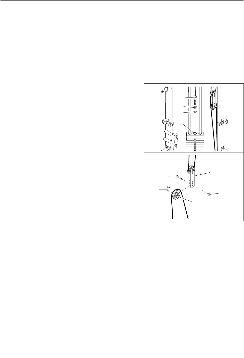
42. Place a 1/2” Flat Washer (11) on top of the Weight
Tube (17).
Thread a 1/2” Plain Nut (45) halfway onto the bolt
on the Weight Cable (72). Screw the bolt on the
Weight Cable into the Weight Tube (17) a couple of
turns.
Tighten the 1/2” Plain Nut (45) down onto the 1/2”
Flat Washer (11).
39
40
41
23
50
47
72
22
54
24
82
54
24
50 57
72
9
72
17
45
11
42
50
Bracket
72
25
17
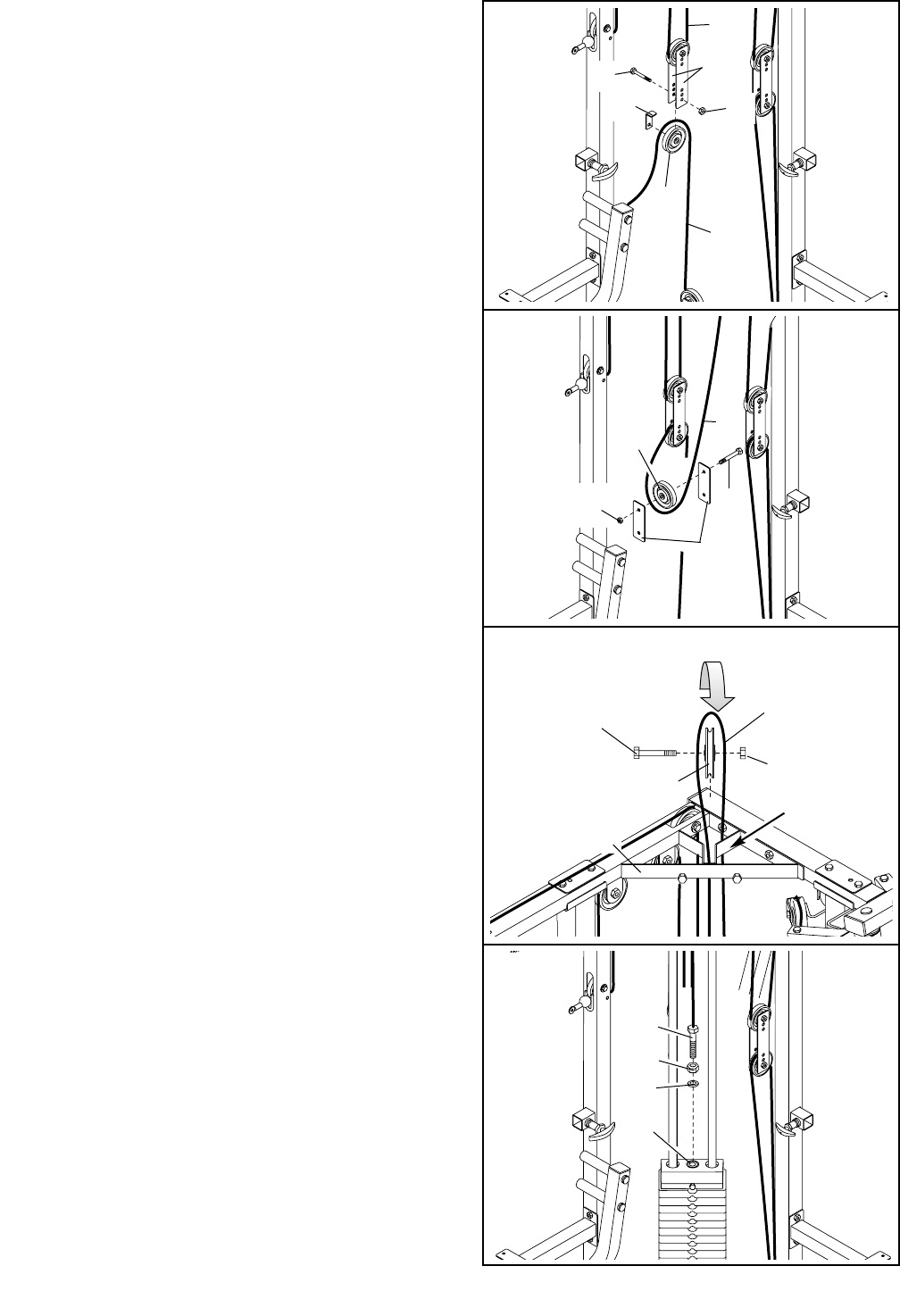
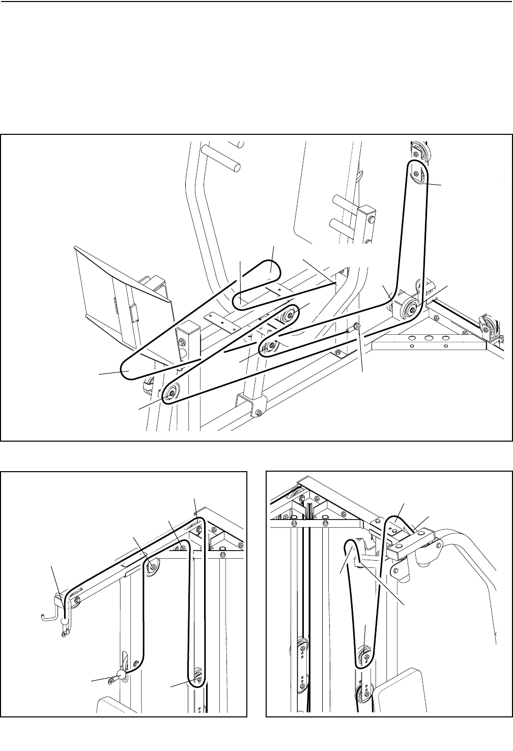
43. Locate the Leg Press Cable (75). Attach the Leg
Press Cable to the indicated side of the Press
Upright (2) with a 3/8” x 3 1/4” Bolt (62) and a 3/8”
Nylon Locknut (50). Do not tighten the Nylon
Locknut yet.
Wrap the Leg Press Cable (75) up around a 3 1/2”
Pulley (24) in the direction shown. Attach the 3 1/2”
Pulley and a Cable Trap (25) to the indicated side
of the Press Frame (8) with a 3/8” x 4 3/4” Bolt (60)
and a 3/8” Nylon Locknut (50). Do not tighten the
Nylon Locknut yet. Be sure that the Cable Trap
is turned to hold the Cable in place.
44. Wrap the Leg Press Cable (75) around a 3 1/2”
Pulley (24) in the direction shown. Attach the 3 1/2”
Pulley and a Cable Trap (25) to the indicated side
of the Press Seat Frame (7) with a 3/8” x 4 3/4” Bolt
(60) and a 3/8” Nylon Locknut (50). Do not tighten
the Nylon Locknut yet. Be sure that the Cable
Trap is turned to hold the Cable in place.
45. Wrap the Leg Press Cable (75) around a 3 1/2”
Pulley (24) in the direction shown. Attach the 3 1/2”
Pulley and a Cable Trap (25) to the indicated side
of the Press Leg Lever (90) with a 3/8” x 4 3/4” Bolt
(60) and a 3/8” Nylon Jamnut (63). Do not tighten
the Nylon Locknut yet. Be sure that the Cable
Trap is turned to hold the Cable in place.
46. Wrap the Leg Press Cable (75) around a 3 1/2”
Pulley (24). Attach the 3 1/2” Pulley and a Cable
Trap (25) to the indicated side of the Press Base (6)
with a 3/8” x 5 1/2” Bolt (55) and a 3/8” Nylon
Locknut (50). Do not tighten the Nylon Locknut
yet. Be sure that the Cable Trap is turned to
hold the Cable in place.
Wrap the Leg Press Cable (75) around another
3 1/2” Pulley (24). Attach the 3 1/2” Pulley between
the Small Pulley Plates (22) with a 3/8” x 1 3/4” Bolt
(57) and a 3/8” Nylon Locknut (50) that was
removed in step 40. Be sure the Leg Press Cable
is routed so that it crosses from one side of the
Press Base (6) to the other.
46
43
44
45
62
2
7
25 850
75
60
75
50
24
55
22
57
50
25
50
7
24
63
90
75 25
60
24
75
24
60
25
6
18
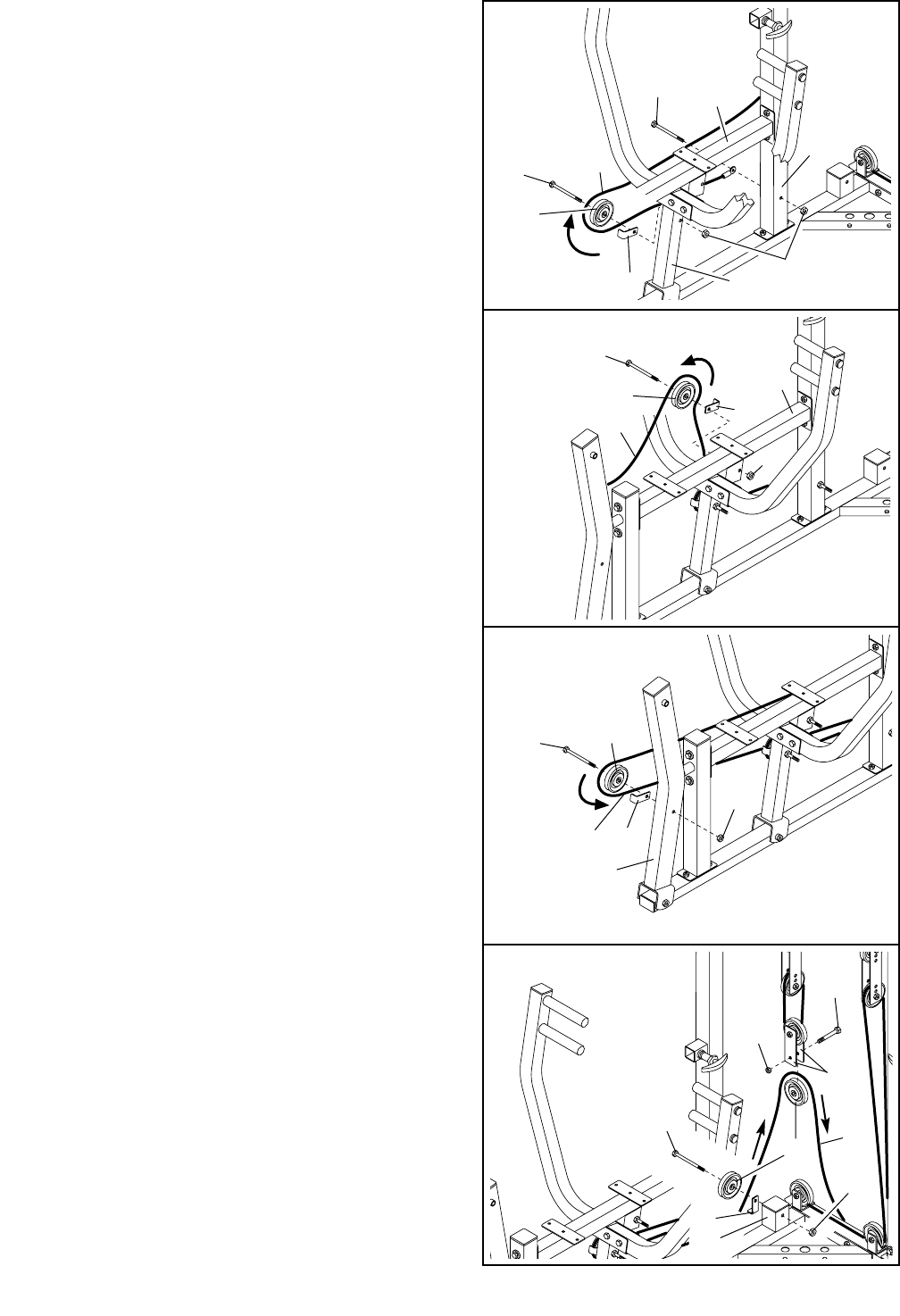
47. Remove the 3/8” Nylon Locknut (50) from the indi-
cated 3/8” x 5 1/2” Bolt (55).
Wrap the Leg Press Cable (75) around a 3 1/2”
Pulley (24). Secure the 3 1/2” Pulley and a Cable
Trap (25) to the 3/8” x 5 1/2” Bolt (55) on the indi-
cated side of the Press Base (6) with the 3/8” Nylon
Locknut (50). Be sure the Cable Trap is oriented
to hold the Cable in place.
Press a 2 1/2” Square Inner Cap (76) into the Press
Base (6).
49. Remove the indicated 3/8” Nylon Locknuts (50).
Wrap the Leg Press Cable (75) around a 3 1/2”
Pulley (24). Attach the 3 1/2” Pulley and a Cable
Trap (25) to the 3/8” x 4 3/4” Bolt (60) on the indi-
cated side of the Press Seat Frame (7) with the first
3/8” Nylon Locknut (50).
Wrap the Leg Press Cable (75) around a 3 1/2”
Pulley (24). Attach the 3 1/2” Pulley and a Cable
Trap (25) to the 3/8” x 4 3/4” Bolt (60) on the indi-
cated side of the Press Frame (8) with a 3/8” Nylon
Locknut (50).
Be sure the Cable Traps (25) are oriented to
hold the Cable (75) in place.
48. Remove the 3/8” Nylon Jamnut (63) from the indi-
cated 3/8” x 4 3/4” Bolt (60).
Wrap the Leg Press Cable (75) around a 3 1/2”
Pulley (24) in the direction shown. Secure the 3 1/2”
Pulley and a Cable Trap (25) to the 3/8” x 4 3/4”
Bolt (60) on the indicated side of the Press Leg
Lever (90) with the 3/8” Nylon Jamnut (63). Be sure
the Cable Trap is oriented to hold the Cable in
place.
50. Remove the indicated 3/8” Nylon Locknut (50).
Attach the Leg Press Cable (75) to the 3/8” x 3 1/4”
Bolt (62) on the indicated side of the Press Upright
(2) with the 3/8” Nylon Locknut (50).
47
48
49
50
75
25
90
60
63
24
25
55
76
650
75
62
50
75
2
50
75
24
8
24
60
7
24
25
25
19
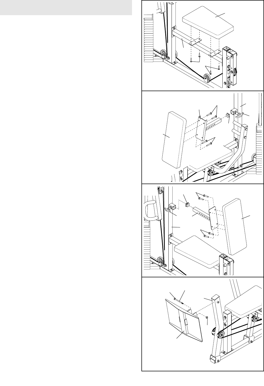
51. Locate and open the parts bag labeled “SEAT
ASSEMBLY.”
Attach a Seat (13) to the brackets on the Butterfly
Seat Frame (14) using four 1/4” x 3/4” Bolts (49).
Repeat this step with the other Seat (not shown)
and the Press Seat Frame (not shown).
52. Press a 1 1/2” Square Inner Cap (35) into the end
of the Press Backrest Frame (44). Attach a
Backrest (12) to the Press Backrest Frame with four
1/4” x 3/4” Bolts (49).
Pull out the Adjustment Knob (5) on the Press
Upright (2) as far as it can go. Slide the Press
Backrest Frame (44) into the Press Upright and
snap the Adjustment Knob into a hole in the Press
Backrest Frame. Turn the Adjustment Knob clock-
wise until tight.
53. Press a 1 1/2” Square Inner Cap (35) into the end
of the Butterfly Backrest Frame (70). Attach the
other Backrest (12) to the Butterfly Backrest Frame
with four 1/4” x 3/4” Bolts (49).
Pull out the Adjustment Knob (5) on the Butterfly
Upright (1) as far as it can go. Slide the Butterfly
Backrest Frame (70) into the Butterfly Upright and
snap the Adjustment Knob into a hole in the
Butterfly Backrest Frame. Turn the Adjustment
Knob clockwise until tight.
51
52
53
2
49
49
12
44
13
12
35
70
1
5
5
49
49
49
14
35
SEAT ASSEMBLY
54
54. Lubricate a 1/2” x 4” Bolt (68). Attach the Foot
Press Plate (29) to the Press Leg Lever (90) with
the Bolt and a 1/2” Nylon Jamnut (36). 90
29
Lubricate
68
36
20
55
56
91
46
3
39
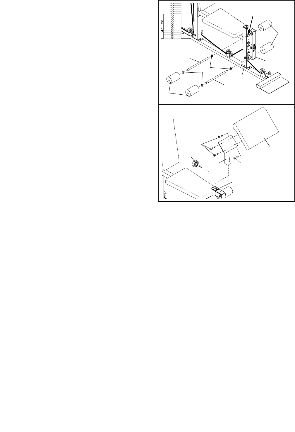
55. Press two 3/4” Round Inner Caps (43) into each of
the two Pad Tubes (42).
Slide a Foam Pad (30) onto one side of a Pad Tube
(42). Slide the Pad Tube through the hole in the
Leg Lever (41). Slide another Foam Pad onto the
other side of the Pad Tube.
Slide a Foam Pad (30) onto one side of the other
Pad Tube (42). Insert the Pad Tube through the
welded tube on the Butterfly Front Leg (3). Slide
another Foam Pad onto the other side of the Pad
Tube.
56. Attach the Curl Pad (91) to the Preacher Post (39)
with four 1/4” x 3/4” Bolts (49).
Slide the Preacher Post (39) into the Butterfly Front
Leg (3) and secure it by inserting the Large
Adjustment Knob (46) and turning it clockwise until
tight.
57. Make sure that all parts have been properly tightened. The use of the remaining parts will be explained in
ADJUSTMENTS, beginning on page 21 of this manual.
Before using the weight system, pull each cable a few times to be sure that the cables move smoothly over
the pulleys. If one of the cables does not move smoothly, find and correct the problem. IMPORTANT: If the
cables are not properly installed, they may be damaged when heavy weight is used. See the CABLE
DIAGRAMS on page 25 and 26 of this manual for proper cable routing. If there is any slack in the
cables, you will need to remove the slack by tightening the cables. See TROUBLESHOOTING on
page 24.
41
30
Welded
Tube
30
43
42
42
3
49
49
21
ADJUSTMENTS
The instructions below describe how each part of the weight system can be adjusted. Refer to the exercise
guide accompanying this manual to see how the weight system should be set up for each exercise. IMPOR-
TANT: When attaching the lat bar, ab strap, or nylon strap, make sure that the attachments are in the cor-
rect starting position for the exercise to be performed. If there is any slack in the cables or chain as an
exercise is performed, the effectiveness of the exercise will be reduced.
47
81
67
69
61
19
21
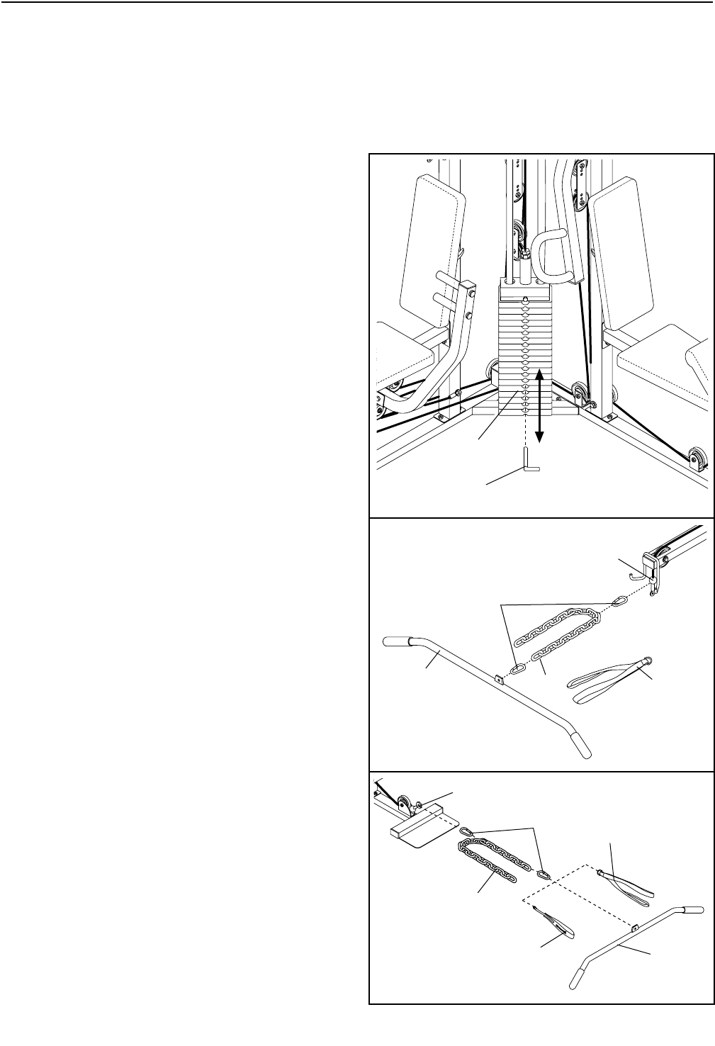
CHANGING THE WEIGHT SETTING
To change the weight setting of the weight stack,
insert the Weight Pin (19) under the desired Weight
(21) until the bent end of the Weight Pin is touching
the Weights. Turn the bent end downward. The
weight setting can be changed from 10 pounds to 200
pounds, in 10 pound increments. Note: Due to the
cables and pulleys, the amount of resistance at
each exercise station may vary from the weight
setting. Use the WEIGHT RESISTANCE CHART on
page 23 to find the approximate amount of resis-
tance at each weight station.
ATTACHING THE LAT BAR OR AB STRAP TO THE
HIGH PULLEY STATION
Attach the Lat Bar (61) to the Ab Cable (47) with a
Cable Clip (69). For some exercises, the Chain (67)
should be attached between the Lat Bar and the Ab
Cable with two Cable Clips. Adjust the length of the
Chain between the Lat Bar and the Ab Cable so the
Lat Bar is in the correct starting position for the
exercise to be performed.
The Ab Strap (81) can be attached in the same manner.
ATTACHING THE LAT BAR, AB STRAP, OR NYLON
STRAP TO THE LOW PULLEY STATION
Attach the Lat Bar (61) to the Weight Cable (72) with a
Cable Clip (69). For some exercises, the Chain (67)
should be attached between the Lat Bar and the Weight
Cable with two Cable Clips. Adjust the length of the
Chain between the Lat Bar and the Weight Cable so
the Lat Bar is in the correct starting position for the
exercise to be performed.
The Ab Strap (81) or Nylon Strap (26) can be attached
in the same manner.
61
26
72
67
69 81
22
ATTACHING THE AB STRAP TO THE AB PULLEY
STATION
Attach the Ab Strap (81) to the Ab Cable (47) at the ab
pulley station with a Cable Clip (69).
ADJUSTING THE BACKREST
To adjust a Backrest (12), loosen the Adjustment Knob
(5) on the Press Upright (2) or the Butterfly Upright
(not shown) by turning it counterclockwise and pulling
it out as far as possible. Slide the Backrest forward or
backward to the desired position, and snap the
Adjustment Knob into a hole in the Backrest Frame
(not shown). Secure the Backrest by turning the
Adjustment Knob clockwise until tight.
ADJUSTING THE CURL PAD
Remove the Large Adjustment Knob (46) from the
Butterfly Front Leg (3).
Align the holes in the Butterfly Front Leg (3) with the
desired set of holes in the Preacher Post (39). Re-
insert the Large Adjustment Knob (46) through the
holes in the Butterfly Front Leg and the holes in the
Preacher Post. Turn the Large Adjustment Knob clock-
wise until tight.
Note: When not using the Curl Pad (91), store it
away from the weight system.
12
2
5
47
81
69
39
91
46
3

23
WEIGHT RESISTANCE CHART
This chart shows the approximate weight resistance at each weight station. “Top” refers to the 10 lb. top weight.
The other numbers refer to the 10 lb. weight plates. The butterfly arm resistance listed is the resistance for each
butterfly arm. Note: The actual resistance at each weight station may vary due to differences in individual
weight plates, as well as friction between the cables, pulleys, and weight guides.
WEIGHT PRESS BUTTERFLY LEG HIGH LOW AB LEG
PLATES ARM ARM LEVER PULLEY PULLEY PULLEY PRESS
(lbs.) (lbs.) (lbs.) (lbs.) (lbs.) (lbs.) (lbs.)
Top15141812221418
128213123332538
240284434443658
352365745554778
465437056675998
5775082677870118
6905795788981138
7 102 64 108 89 101 92 158
8 114 72 121 100 112 103 178
9 127 79 133 111 123 115 198
10 139 86 146 121 134 126 218
11 152 93 159 132 146 137 239
12 164 100 172 143 157 148 259
13 176 108 185 154 168 159 279
14 189 115 197 165 180 171 299
15 201 122 210 176 191 182 319
16 214 129 223 187 202 193 339
17 226 137 236 198 213 204 359
18 238 144 248 209 225 215 379
19 251 151 261 220 236 227 399
TROUBLESHOOTING
Inspect and tighten all parts each time the weight system is used. Replace any worn parts immediately. The
weight system can be cleaned using a damp cloth and mild non-abrasive detergent. Do not use solvents.
TIGHTENING THE CABLES
Woven cable, the type of cable used on the weight system, can stretch slightly when it is first used. If there is
slack in the cables before resistance is felt, the cables should be tightened.
To tighten the cables, first insert the weight pin into the middle of the weight stack. Slack can be removed from
these cables several ways:
See drawing 1. Loosen the 1/2” Plain Nut (45) on the Weight
Cable (72) bolt, away from the 1/2” Flat Washer (11). Screw
the bolt a few turns into the Weight Tube (17). Retighten the
1/2” Plain Nut down onto the 1/2” Flat Washer.
See drawing 2. Remove either the upper or lower 3/8” Nylon
Locknut (50) and 3/8” x 2” Bolt (54) from the Adjustable
Pulley Plates (23). Remove the 3 1/2” Pulley (24) and the
Cable Trap (25). Reattach the 3 1/2” Pulley and the Cable
Trap to a hole closer to the center of the Adjustable Pulley
Plates with the 3/8” x 2” Bolt and 3/8” Nylon Locknut.
Either set of Adjustable Pulley Plates (23) can be adjust-
ed in this manner.
Do not overtighten the cables. If the cables are over tightened, the top weight will be lifted off the weight
stack. If a cable tends to slip off the pulleys often, it may have become twisted. Remove the cable and
re-install it.
If the cables need to be replaced, see ORDERING REPLACEMENT PARTS on the back cover of this manual.
24
11
23
54
72
17
50
24
45
25
2
1
25
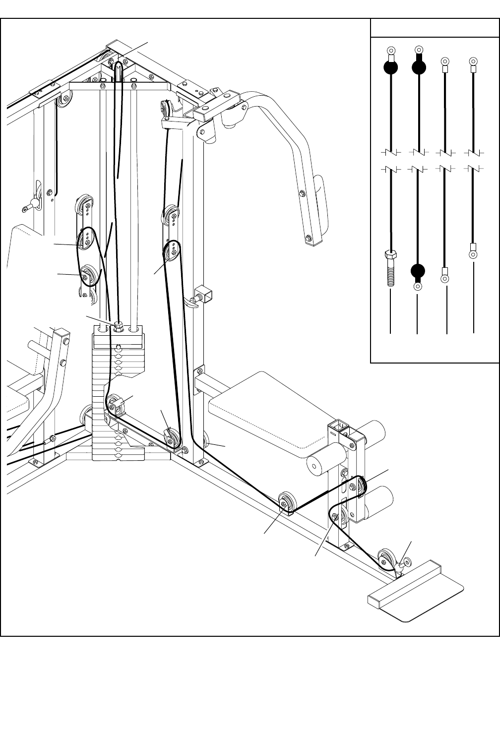
CABLE DIAGRAMS
The cable diagrams on this page and the next page show the proper routing of the Leg Press Cable (75), the Ab
Cable (47), the Butterfly Cable (73), and the Weight Cable (72). Use the diagrams to be sure that the Cables
have been assembled correctly. The starting and ending points of each Cable have been labeled. The numbers
show the proper route for each Cable. IMPORTANT: If the Cables have not been correctly routed, the
weight system will not function properly and damage may occur.
Butterfly Cable (73)
Leg Press Cable (75)
2
4
1—Right Arm
3
5—Left Arm
10
8
9
3
7
6
2
1—Press Upright
4
5
Ab Cable (47)
6—Ab Pulley
1—High Pulley
2
3
4
5
11—Press Upright
26
Weight Cable (72)
2
3
1—Low Pulley
4
8
11
12—Weight
Stack
7
6
5
Cable ID
72 47 75 73
9
10

27
NOTES
2" x 3” Inner Cap (78)
2" Square Inner Cap (28)
1 1/2" Square Inner Cap (35)
1 1/2" x 2 1/2” Inner Cap (83)
2 1/2" Square Inner Cap (76)
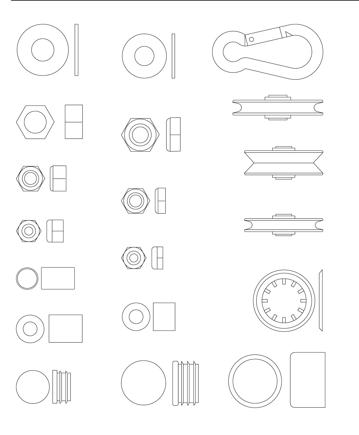
5/16" Nylon Jamnut (34)
Cable Clip (69)
"V" Pulley (27)
(Not shown to scale)
3 1/2" Pulley (24)
(Not shown to scale)
Retainer Ring (31)
4 1/2" Pulley (82)
(Not shown to scale)
1/2" Flat Washer (11)
1/2" Plain Nut (45)
1/2" Nylon Jamnut (36)
5/16" Nylon Locknut (64)
3/8" Nylon Jamnut (63)
3/8" Nylon Locknut (50)
3/8" Flat Washer (48)
1/2" x 3/4" Spacer (97)
1" Round Outer Cap (38)
1" Round Inner Cap (86)
3/4" Round Inner Cap (43)
5/8" x 1/2" Spacer (93)
5/8” x 3/4” Bushing (66)
PART IDENTIFICATION CHART—Model No. WESY37531 R1003A
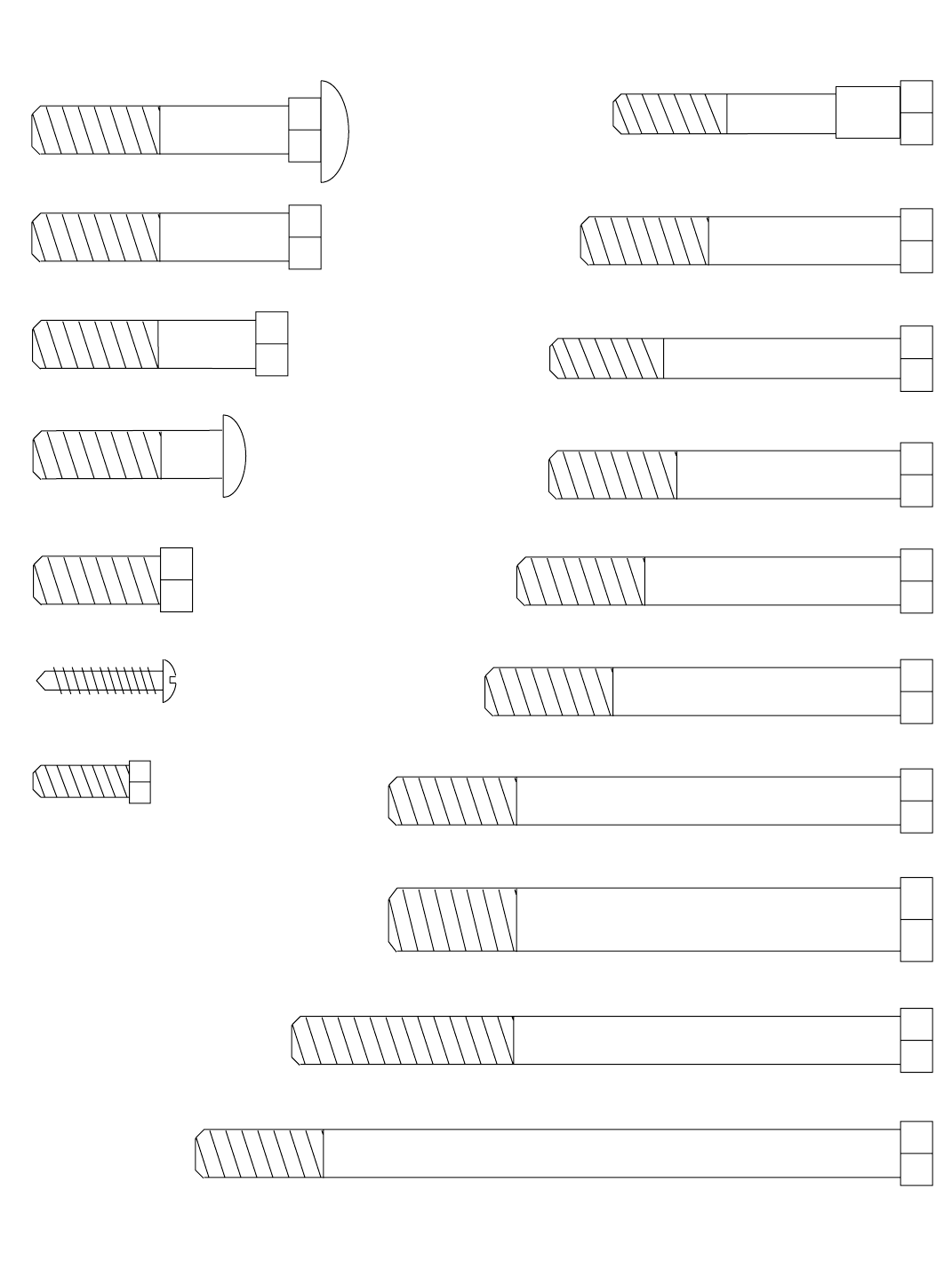
5/16" x 2 1/4" Shoulder Bolt (79)
3/8" x 1" Bolt (84)
3/8" x 1 3/4" Bolt (57)
3/8" x 1 1/2" Button Head Bolt (98)
1/4" x 3/4" Bolt (49) 3/8" x 4" Bolt (59)
1/2" x 4" Bolt (68)
3/8" x 4 3/4" Bolt (60)
3/8" x 2 1/2" Bolt (87)
3/8" x 2 3/4" Bolt (89)
3/8" x 3" Bolt (88)
3/8" x 3 1/4" Bolt (62)
5/16" x 2 3/4" Bolt (96)
1" Tap Screw (80)
3/8" x 2" Carriage Bolt (92)
3/8" x 2" Bolt (54)
3/8" x 5 1/2" Bolt (55)

PART LIST—Model No. WESY37531 R1003A
Note: “#” indicates a non-illustrated part. Specifications are subject to change without notice.
Key No. Qty. Description Key No. Qty. Description
1 1 Butterfly Upright
2 1 Press Upright
3 1 Butterfly Front Leg
4 1 Butterfly Base
5 2 Adjustment Knob
6 1 Press Base
7 1 Press Seat Frame
8 1 Press Frame
9 1 Press Top Frame
10 2 Butterfly Arm
11 1 1/2” Flat Washer
12 2 Backrest
13 2 Seat
14 1 Butterfly Seat Frame
15 2 Weight Guide
16 1 Top Weight
17 1 Weight Tube
18 1 Weight Tube Bumper
19 1 Weight Pin
20 1 Press Front Leg
21 19 Weight
22 2 Small Pulley Plate
23 4 Adjustable Pulley Plate
24 26 3 1/2” Pulley
25 15 Cable Trap
26 1 Ankle Strap
27 2 “V”-Pulley
28 6 2” Square Inner Cap
29 1 Foot Press Plate
30 4 Foam Pad
31 4 Retainer Ring
32 2 Large Cable Trap
33 1 Butterfly Top Frame
34 2 5/16” Nylon Jamnut
35 4 1 1/2” Square Inner Cap
36 3 1/2” Nylon Jamnut
37 4 Pivot Arm Bushing
38 2 1” Round Outer Cap
39 1 Preacher Post
40 2 Bumper
41 1 Leg Lever
42 2 Pad Tube
43 4 3/4” Round Inner Cap
44 1 Press Backrest Frame
45 1 1/2” Plain Nut
46 1 Large Adjustment Knob
47 1 Ab Cable
48 31 3/8” Flat Washer
49 20 1/4” x 3/4” Bolt
50 52 3/8” Nylon Locknut
51 2 Weight Bumper
52 1 Plastic Bushing
53 2 Butterfly Handle
54 9 3/8” x 2” Bolt
55 1 3/8” x 5 1/2” Bolt
56 38 Weight Insert
57 6 3/8” x 1 3/4” Bolt
58 4 Butterfly Arm Bushing
59 1 3/8” x 4” Bolt
60 3 3/8” x 4 3/4” Bolt
61 1 Lat Bar
62 19 3/8” x 3 1/4” Bolt
63 5 3/8” Nylon Jamnut
64 4 5/16” Nylon Locknut
65 6 Press Grip
66 8 5/8” x 3/4” Bushing
67 1 Chain
68 3 1/2” x 4” Bolt
69 3 Cable Clip
70 1 Butterfly Backrest Frame
71 1 Left Pivot Arm
72 1 Weight Cable
73 1 Butterfly Cable
74 2 Butterfly Grip
75 1 Leg Press Cable
76 2 2 1/2” Square Inner Cap
77 2 Press Arm
78 1 2” x 3” Inner Cap
79 2 5/16” x 2 1/4” Shoulder Bolt
80 2 1” Tap Screw
81 1 Ab Strap
82 1 4 1/2” Pulley
83 8 1 1/2” x 2 1/2” Inner Cap
84 4 3/8” x 1” Bolt
85 1 Right Pivot Arm
86 4 1” Round Inner Cap
87 6 3/8” x 2 1/2” Bolt
88 1 3/8” x 3” Bolt
89 3 3/8” x 2 3/4” Bolt
90 1 Press Leg Lever
91 1 Curl Pad
92 8 3/8” x 2” Carriage Bolt
93 2 5/8” x 1/2” Spacer
94 2 Support Plate
95 1 Plastic Weight Cover
96 4 5/16” x 2 3/4” Bolt
97 1 1/2” x 3/4” Spacer
98 1 3/8” x 1 1/2” Button Head Bolt
# 1 User’s Manual
# 1 Exercise Guide
92
92
49
39 49
23
25 24
25
24 23
50
54
23
25 24
25
24
23
50
44
35
49
86
65
77 28
65
86
77
64
25
24
60
96
68
36
25 24 50
8
68
29
36
68
36
63
25 24
25
24
60 90
78
62
48
50
80 40
20
50
83
6
60
24
25
50
50
49
50
24
25
50
7
50
50 25
24 50
25
24
55
50
50
48
62
5
47
66
66
50
48
48
62
2
47
13
50
75
62
75
83
48
62
50
48
24
66 94
87 48
62
66 24
66
50
4850
54 82
50
9
24 50
54
24
50
72
45
11
50
57
17
15
21
51
95
16
97 98
24
22
24
50
57 43
42
43
63
92 50
92
50
83
72
83
54
24
54
24
50
48
50
25
24
57
62
46 52
40
80
48
48
62
62
50
66 24
66
4
3
83
57
24
25
63
30
43
42
43
28
41
48
50
93 24
93
30
89
48
28
63
88
30
12
49
70
35
49
13
50
50
49
49
50
14 50
63 48
50
50
59
24
48
62
5
1
27
32
50
50
38
31
31
83
83
83
33
48
48
62
87
94
79
73
34
50
85
37
37 62
37
62
37 50
10
53
84
28
84
53
28
48
48
50 50
48
48
48
89
56
87
50
25
48
48
74
74
10
71
58
58
58
58
50 50
69
67
81 26
61
65
65
18
12 49
28
54
91
30
22
19
76
76
89
50
57
49
79
73
34
27
32 87
50
35
35
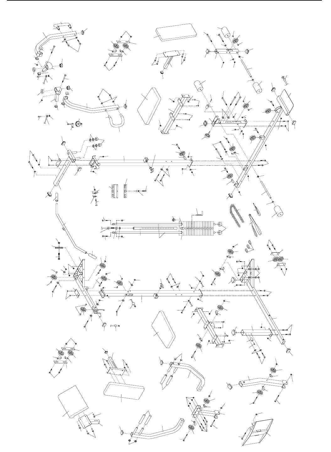
EXPLODED DRAWING—Model No. WESY37531 R1003A

ORDERING REPLACEMENT PARTS
To order replacement parts, simply call our Customer Service Department toll-free at 1-800-999-3756, Monday
through Friday, 6 a.m. until 6 p.m. Mountain Time (excluding holidays). To help us assist you, please be pre-
pared to give the following information:
• The MODEL NUMBER of the product (WESY37531)
• The NAME of the product (WEIDER®PRO 3770 weight system)
• The SERIAL NUMBER of the product (see the front cover of this manual)
• The KEY NUMBER and DESCRIPTION of the part(s) (see the PART LIST and EXPLODED DRAWING
attached at the center of this manual)
Part No. 205597 R1003A Printed in Canada © 2003 ICON Health & Fitness, Inc.
LIMITED WARRANTY
ICON Health & Fitness, Inc. (ICON), warrants this product to be free from defects in workmanship and
material, under normal use and service conditions, for a period of ninety (90) days from the date of pur-
chase. This warranty extends only to the original purchaser. ICON's obligation under this warranty is lim-
ited to replacing or repairing, at ICON's option, the product at one of its authorized service centers. All
products for which warranty claim is made must be received by ICON at one of its authorized service cen-
ters with all freight and other transportation charges prepaid, accompanied by sufficient proof of purchase.
All returns must be pre-authorized by ICON. This warranty does not extend to any product or damage to
a product caused by or attributable to freight damage, abuse, misuse, improper or abnormal usage or
repairs not provided by an ICON authorized service center, products used for commercial or rental pur-
poses, or products used as store display models. No other warranty beyond that specifically set forth
above is authorized by ICON.
ICON is not responsible or liable for indirect, special or consequential damages arising out of or in con-
nection with the use or performance of the product or damages with respect to any economic loss, loss
of property, loss of revenues or profits, loss of enjoyment or use, costs of removal, installation or other
consequential damages of whatsoever nature. Some states do not allow the exclusion or limitation of inci-
dental or consequential damages. Accordingly, the above limitation may not apply to you.
The warranty extended hereunder is in lieu of any and all other warranties and any implied warranties of
merchantability or fitness for a particular purpose is limited in its scope and duration to the terms set forth
herein. Some states do not allow limitations on how long an implied warranty lasts. Accordingly, the above
limitation may not apply to you.
This warranty gives you specific legal rights. You may also have other rights which vary from state to state.
ICON HEALTH & FITNESS, INC., 1500 S. 1000 W., LOGAN, UT 84321-9813
