Weil Mclain Lgb 4 Users Manual 550 141 918_0304.pmd
LGB-5 to the manual c44faa93-b091-45fc-942b-245740f9694e
2015-02-02
: Weil-Mclain Weil-Mclain-Lgb-4-Users-Manual-454288 weil-mclain-lgb-4-users-manual-454288 weil-mclain pdf
Open the PDF directly: View PDF ![]() .
.
Page Count: 8
Part Number 550-141-918/0304
LGLG
LGLG
LGBB
BB
B
Refer to
LGBLGB
LGBLGB
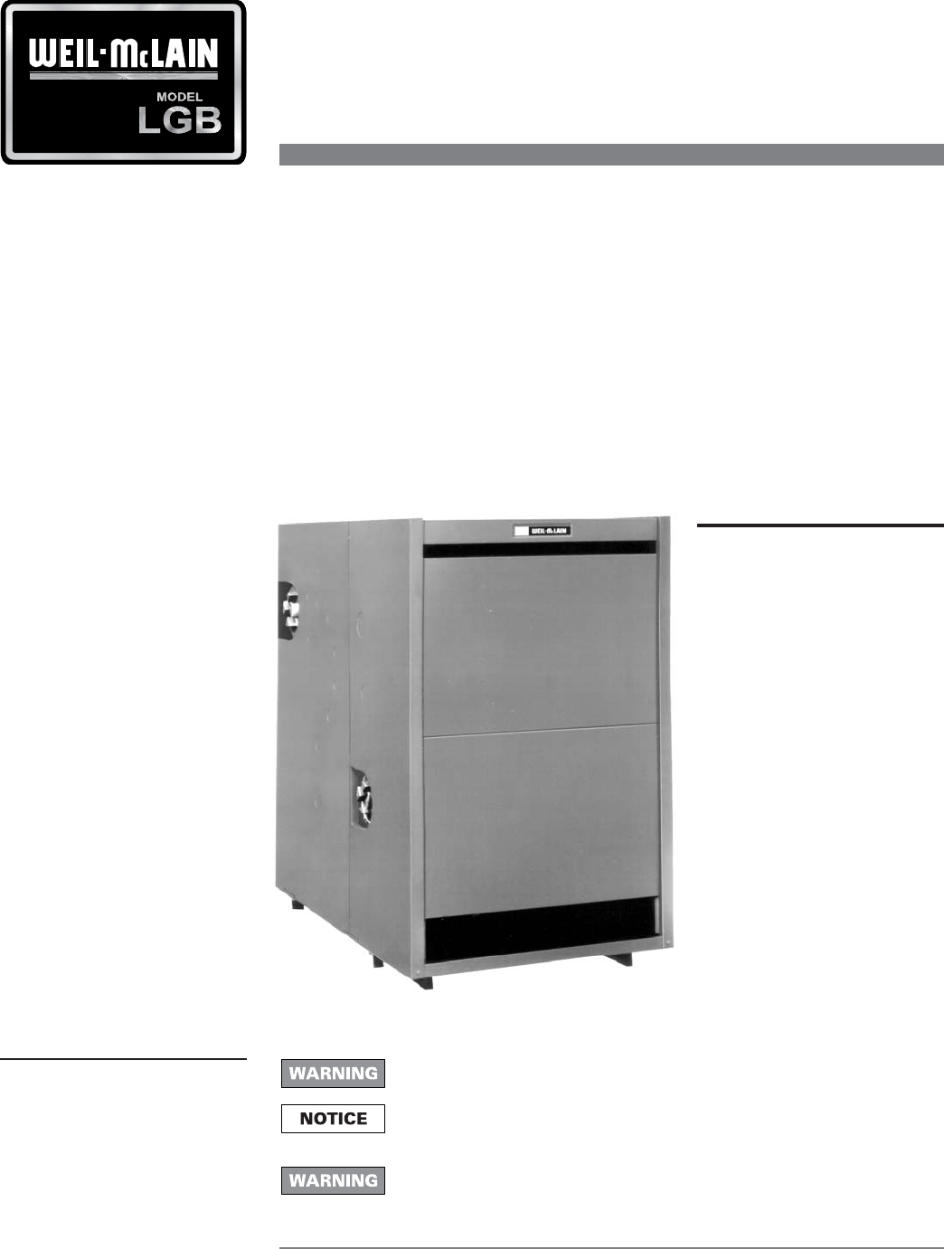
LGB • Installation •
Start-Up • Service •
Parts Manual
for additional information
Control Supplement must only be used by a qualified installer/service
technician. Read all instructions before installing. Failure to follow all
instructions in proper order can cause severe personal injury, death or
substantial property damage.
Contents
Installation ....................... 2
Gas piping ......................... 3
Wiring ............................... 4
Operating instructions ..... 6
Verification testing .......... 7
Parts ................................. 8
These terms are used throughout this
manual to bring attention to the presence
of hazards of various risk levels or to
important information concerning the life
of the product.
Gas–fired boiler
Control SupplementControl Supplement
Control SupplementControl Supplement
Control Supplement
LGBLGB
LGBLGB
LGB-4 -4
-4 -4
-4 & LGB LGB
LGB LGB
LGB-5-5
-5-5
-5 Series 2 – Natural gas
Universal Control System
Indicates presence of hazards that can cause severe personal injury, death or
substantial property damage.
Indicates special instructions on installation, operation or maintenance that
are important but not related to personal injury or property.
Part Number 550-141-918/0304
LGBLGB
LGBLGB
LGB-4 -4
-4 -4
-4 & 5 5
5 5
5
•
Control Supplement
•
UCS
•
Nat. Gas
2
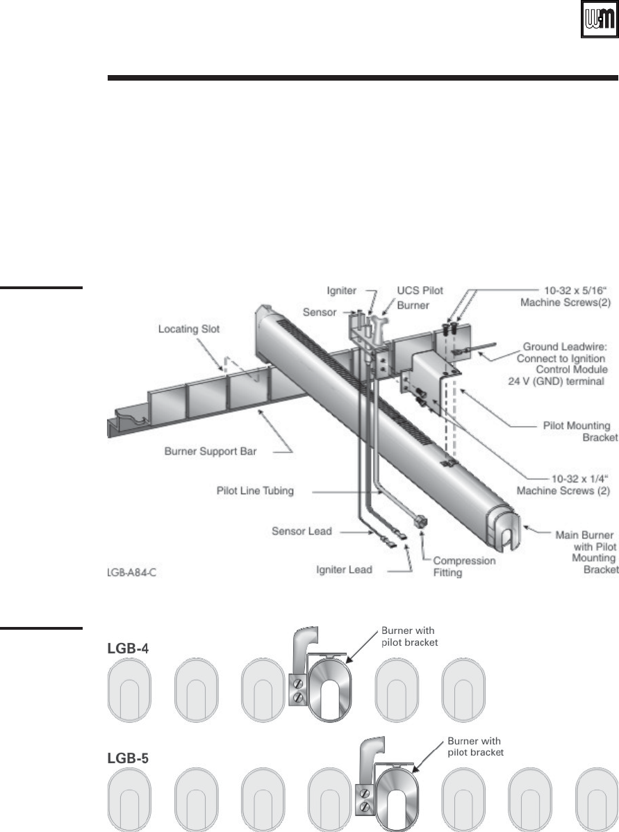
Figure 1a
Pilot burner
assembly
Figure 1b
Pilot location
Install pilot burner. See Figures 1a and 1b. Follow Figure 1b for pilot burner location, placing
the burner with pilot bracket in the fourth position from the left for the LGB-4 and the fifth
position from the left for the LGB-5, as shown.
Install gas controls and ignition control as shown in Figure 3 on page 7.
In Canada — mount rating plate on interior jacket panel.
IInstallation
Part Number 550-141-918/0304
LGBLGB
LGBLGB
LGB-4 -4
-4 -4
-4 & 5 5
5 5
5
•
Control Supplement
•
UCS
•
Nat. Gas
3
Table 1
Gas supply pipe
capacities
1. Size natural gas piping from Table 1. Size piping to provide proper inlet pressure to gas
valve when operating at rated input.
a. Inlet gas pressure to manual main shut-off gas valve minimum 5" W.C., maximum
13" W.C.
b. If pressure to gas valve exceeds 13" W.C., install 100% lock-up gas pressure regulator
upstream of hand valve.
c. To obtain approximate cubic feet per hour, divide input (Btu/hr) by 1000.
2. Size gas piping considering:
a. Diameter and length of gas supply piping.
b. Number of fittings.
c. Maximum gas consumption (including any possible future expansion).
d. Allowable pressure drop from gas meter to boiler. For pressure drops, see ANSI
Z233.1 latest edition. Canadian installations must comply with B149.1 or B149.2
Installation Code.
3. Remove knockout disc from jacket panel side to which gas supply will be piped.
4. Follow good piping practices.
5. Pipe joint compound (pipe dope) must be resistant to corrosive action of liquefied
petroleum gases. Apply sparingly only to male threads of pipe joints.
6. Install drip leg at inlet of gas connection to boiler. Where local code/utility requires,
extend drip leg to floor.
7. Install ground joint union when required for servicing.
8. Support piping by hangers, not by boiler or its accessories.
9. Purge all air from supply piping.
10. Before operating boiler, check boiler and its gas connections for leaks.
Supply pipe sizing
Connect gas piping
to boiler
10 20 30 40 50 75 100 150
1 1/4" 1,050 730 590 500 440 360 305 250
1 1/2" 1,600 1,100 890 760 670 545 460 380
2" 3,050 2,100 1,650 1,450 1,270 1,020 870 710
2 1/2" 4,800 3,300 2,700 2,300 2,000 1,650 1,400 1,130
3" 8,500 5,900 4,700 4,100 3,600 2,900 2,500 2,000
4" 17,500 12,000 9,700 8,300 7,400 6,000 5,100 4,100
PIPE
SIZE
Pipe length, feet *
(Natural gas capacities given in MBH)
(Specific Gravity 0.60 @ Pressure Loss of 0.30" W.C.)
*Include measured length of gas supply piping and allowance in feet for number and size of fittings.
II Gas piping
Do not check for gas leaks with an open flame - use bubble test. Failure to
use bubble test or check for leaks can cause severe personal injury, death or
substantial property damage.
a. Close manual main shut-off valve during any pressure testing greater than 13" W.C.
b. Disconnect boiler and gas valve from gas supply piping during any pressure test
greater than 13" W.C.
11. In Canada — manual main shut-off valve must be identified by installer.
Part Number 550-141-918/0304
LGBLGB
LGBLGB
LGB-4 -4
-4 -4
-4 & 5 5
5 5
5
•
Control Supplement
•
UCS
•
Nat. Gas
4
III Wiring
Part Number 550-141-918/0304
LGBLGB
LGBLGB
LGB-4 -4
-4 -4
-4 & 5 5
5 5
5
•
Control Supplement
•
UCS
•
Nat. Gas
5
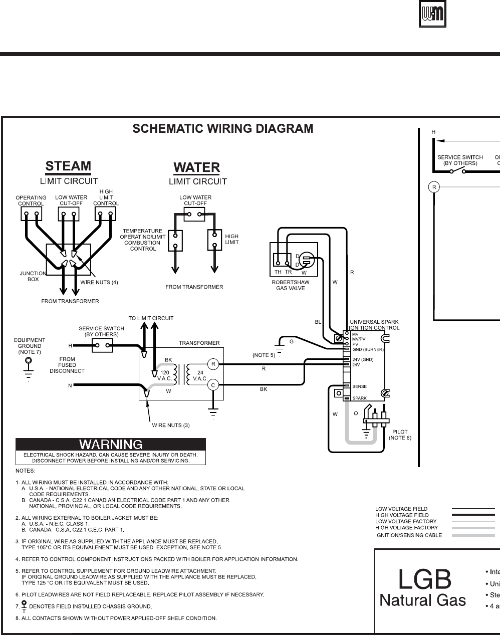
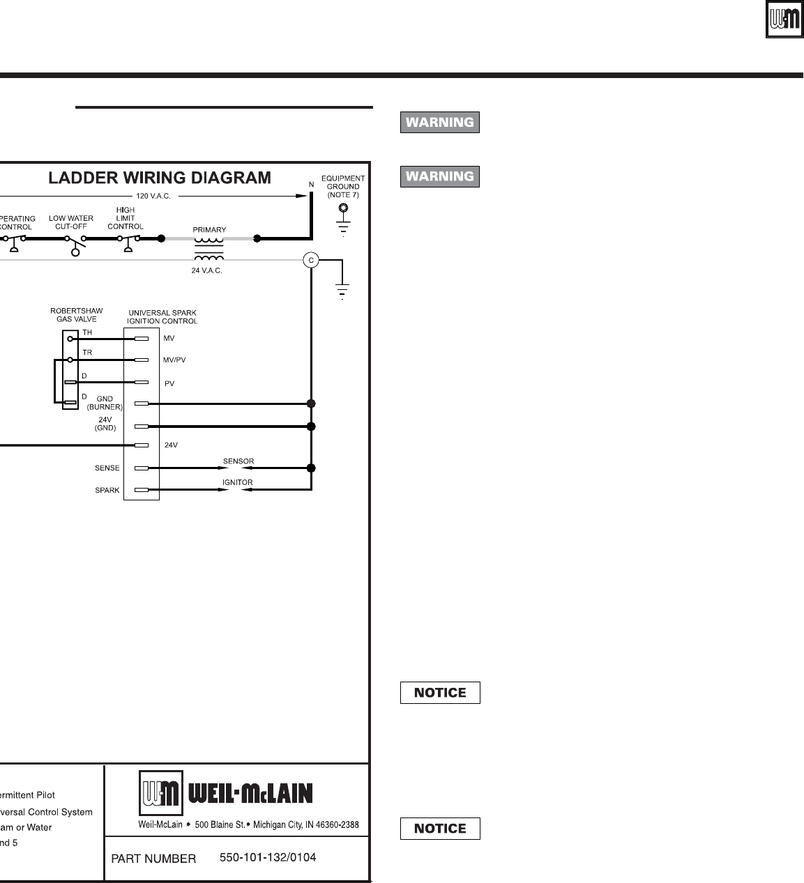
Figure 2 Wiring diagram
Sequence of
operation
1. Operating control begins start-up sequence.
a. Limit control contacts are closed.
2. Ignition control module energized.
a. Pilot gas valve opens.
b. Pilot ignition spark begins.
c. Pilot ignites.
d. Pilot proves.
e. Main gas valve opens.
f. Main burners ignite.
3. Boiler shuts down when operating control
satisfied.
For your safety, turn off power supply before making
electrical connections to avoid possible electrical shock
hazard.
On failure to sense pilot flame, control will wait 5
minutes then retry for ignition.
"Hot" side of line voltage to boiler must be wired
directly to limit circuit, then fed to transformer
primary.
All wiring must be installed according to requirements
of the National Electrical Code and any national, state
or local code requirements having jurisdiction. All
wiring external to boiler jacket must be N.E.C. Class 1.
The boiler must be electrically grounded according to
the National Electrical Code, ANSI/NFPA No. 70 latest
edition. Use 105oC thermoplastic wire, or equivalent, if
any original wire must be replaced. GND (burner)
lead wires must be 125oC wire.
Canadian installations must conform to CSA C22.1
Canadian Electrical Code Part 1 and any local or
provincial codes.
Wiring to boiler must be No. 14 gauge or heavier.
Install in conduit.
A separate electrical circuit with a fused disconnect
switch (15 amp. recommended) should be used for the
boiler.
• Determine right or left electrical supply wiring.
• Attach electrical junction box to inside jacket end
panel. Screws and nuts are provided.
• Attach control transformer to junction box.
• Complete wiring per wiring diagram, Figure 2,
pages 4 and 5.
• Install ignition control ground connection as
shown in Figure 1 and wiring diagram, Figure 2.
• In Canada — attach chain between junction box
and transformer with S-hooks.
Wiring
procedure
Wiring
requirements
Label all wires prior to disconnection when servicing
controls. Wiring errors can cause improper and
dangerous operation resulting in servere personal
injury, death or substantial property damage.
Part Number 550-141-918/0304
LGBLGB
LGBLGB
LGB-4 -4
-4 -4
-4 & 5 5
5 5
5
•
Control Supplement
•
UCS
•
Nat. Gas
6
A. This boiler is equipped with an ignition device which
automatically lights the pilot. Do not try to light the pilot by
hand.
B. BEFORE OPERATING, smell all around the boiler area for gas.
Be sure to smell next to the floor because some gas is heavier
than air and will settle on the floor.
WHAT TO DO IF YOU SMELL GAS
•Do not try to light any appliance.
•Do not touch any electric switch; do not use any phone
in your building.
•Immediately call your gas supplier from a neighbor's
phone. Follow the gas supplier's instructions.
•If you cannot reach your gas supplier, call the fire
department.
C. Use only your hand to turn the gas control knob. Never use
tools. If the knob will not turn by hand, don't try to repair it,
call a qualified service technician. Force or attempted repair may
result in a fire or explosion.
D. Do not use this appliance if any part has been under water.
Immediately call a qualified service technician to inspect the
appliance and to replace any part of the control system and any
gas control, which has been under water.
1. STOP! Read the safety information above.
2. Set the thermostat to lowest setting.
3. Turn off all electrical power to the appliance.
4. Remove Front Panel.
5. This appliance is also equipped with an
ignition device which automatically lights the
second pilot. Do not try to light this pilot by
hand.
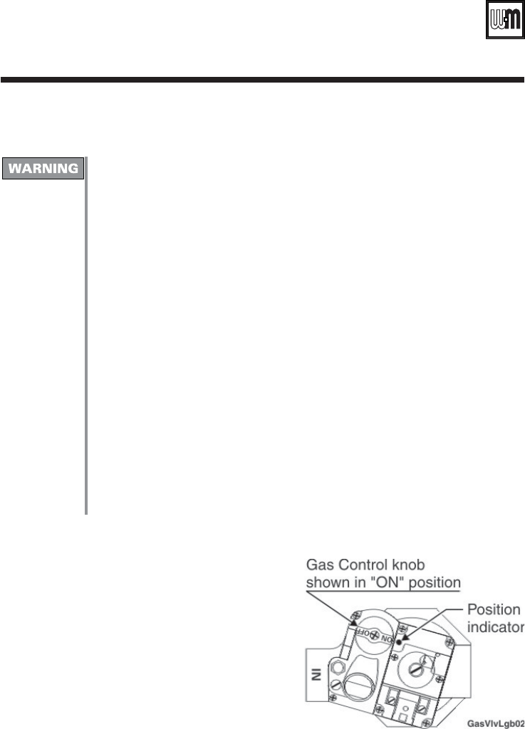
6. Close the firing valve and turn the Gas Control
knob clockwise to "OFF."
7. Wait five (5) minutes to clear out any gas. Then smell for gas, including near the floor.
If you smell gas, STOP! Follow "B" in the safety information above. If you don't smell
gas, go to the next step.
8. Turn Gas Control knob counterclockwise to "ON,”then open the firing valve.
9. Turn on all electric power to the appliance.
10. Set thermostat to desired setting.
11. If the appliance will not operate, close the firing valve and turn off gas to the boiler by
rotating the Gas Control knob clockwise to “OFF.” Turn off all electrical power. Call
your service technician or gas supplier.
12. Replace Front Panel.
Starting
boiler
IV Operating instructions

Part Number 550-141-918/0304
LGBLGB
LGBLGB
LGB-4 -4
-4 -4
-4 & 5 5
5 5
5
•
Control Supplement
•
UCS
•
Nat. Gas
7
VVerification testing
Before starting boiler for the first time and at least annually (during annual inspection and
start-up), follow the procedures below to verify boiler controls are operating correctly and
that automatic gas valve properly shuts off gas flow. Failure to verify boiler operation
could result in severe personal injury, death or substantial property damage.
Replace any defective components. Do not attempt to operate boiler or leave boiler in
operation if any component is found to be defective or to operate incorrectly. Failure to
comply could result in severe personal injury, death, or substantial property damage.
Leak test automatic
gas valve
1. Close manual test firing valve.
2. Open the service valve. Press down and turn automatic gas valve knob (or lever) to
ON.
3. Install a hose barb into a pressure tap downstream of the automatic gas valve. Allow
any accumulated gas in the line to vent off. Then connect a U-tube manometer. If the
valve seals properly, there should be no gas pressure present. Remove manometer and
hose barb and replace pipe plug in pressure tap.
4. Remove the manometer and plug any open pressure taps.
5. Follow Operating Instructions to place boiler in service.
Verify boiler control
sequence
1. Follow the Operating Instructions in this Supplement to start the boiler, but do not
open the manual test firing valve. Open all other manual gas valves as instructed.
Leave the manual test firing valve closed.
2. The automatic pilot burner should light.
3. After the pilot lights, the boiler controls should activate the automatic gas valve. Use a
voltmeter to verify voltage to automatic valve.
4. With no gas flow to the manifold, the boiler ignition controls should turn off the
automatic gas valve after main flame ignition trial. Use a voltmeter to verify voltage to
automatic valve is turned off.
Manual test firing
valve
This boiler is equipped with a manual test firing valve — the manual gas valve piped
between the gas manifold and the automatic gas valve. Closing the manual test firing valve
allows verification of proper boiler operation without allowing gas flow to the manifold
and allows leak testing of the automatic gas valve. Follow the procedures below.
Part Number 550-141-918/0304
LGBLGB
LGBLGB
LGB-4 -4
-4 -4
-4 & 5 5
5 5
5
•
Control Supplement
•
UCS
•
Nat. Gas
8
Weil-McLain
500 Blaine Street
Michigan City, IN 46360-2388
http://www.weil-mclain.com
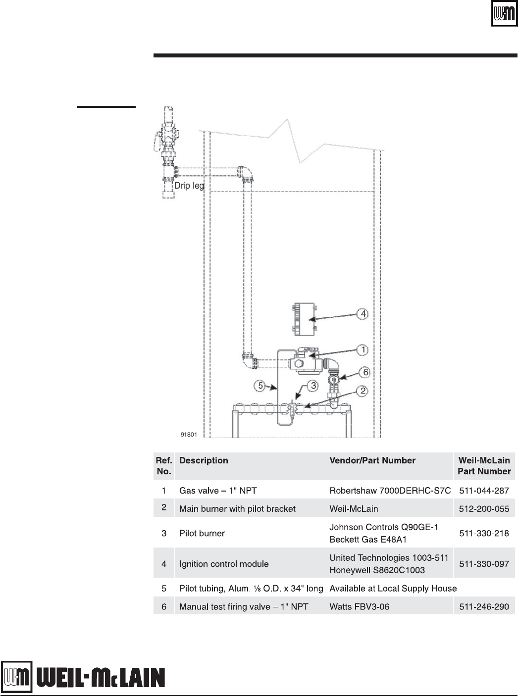
Figure 3
Control and gas
components
VI Parts list
