Weir Group Management Services STXMPM monitor the operation of components of a drilling rig User Manual Name
Weir Group Management Services Limited monitor the operation of components of a drilling rig Name
Contents
- 1. Setup guide
- 2. setup guide
Setup guide

The Weir Group PLC
Weir Mechatronics
1 Marden St
Artarmon, NSW
2064, Australia
Tel: +61 2 9934 5100
Weir Industrial Gateway
Setup guide
Document ID: 00-40-20-40_20
Revision: 0.5
November 15, 2017
Copyright © Weir Minerals Australia Ltd 2017.
Commercial in Confidence. All rights reserved
The Weir Group PLC Weir Industrial Gateway setup guide rev 0.5
Copyright © Weir Minerals Australia Ltd 2017. Commercial in Confidence. All rights reserved. Page i
Document Approval
Name
Designation
Date
Signature
Submitted By
C.Strudwicke
Principle Control
Systems Engineer
Accepted By
C.Strudwicke
Principle Control
Systems Engineer
Approved By
B.Baker
Head of
Mechatronics

The Weir Group PLC Weir Industrial Gateway setup guide rev 0.5
Copyright © Weir Minerals Australia Ltd 2017. Commercial in Confidence. All rights reserved. Page ii
Document History
Revision
Date
Author
Details
0.1
9-3-2017
C.Strudwicke
First version
0.2
21-03-2017
C.Strudwicke
Addition of feedback relating to certification
requirements
0.3
08-09-2017
W. Cooke
Addition of feedback relating to certification
requirements
0.4
10-06-2017
W. Cooke
Addition of feedback relating to certification
requirements
0.5
11-15-2017
W. Cooke
Document name change to match regulatory
documents

The Weir Group PLC Weir Industrial Gateway setup guide rev 0.5
Copyright © Weir Minerals Australia Ltd 2017. Commercial in Confidence. All rights reserved. Page iii
Table of Contents
DOCUMENT APPROVAL .................................................................................................................................. I
DOCUMENT HISTORY .................................................................................................................................... II
1 INTRODUCTION AND SAFETY ................................................................................................................. 1
1.1 INTRODUCTION .......................................................................................................................................... 1
1.2 SCOPE ...................................................................................................................................................... 1
1.3 TARGET AUDIENCE ...................................................................................................................................... 1
1.4 SAFETY ..................................................................................................................................................... 1
1.4.1 Safety Terminology and Symbols ...................................................................................................... 1
1.4.2 User Safety ........................................................................................................................................ 1
1.4.3 Warnings ........................................................................................................................................... 2
1.4.4 Determination That Equipment Can be Used Safely in the Intended Area ........................................ 3
2 TRANSPORTATION AND STORAGE ......................................................................................................... 4
2.1 CONSIGNMENT RECEIPT AND UNPACKING ........................................................................................................ 4
2.2 TRANSPORTATION GUIDELINES ...................................................................................................................... 4
2.3 STORAGE .................................................................................................................................................. 4
3 SYSTEM COMPONENTS ......................................................................................................................... 4
4 SYSTEM ARCHITECTURE ......................................................................................................................... 6
5 PSM – POWER SUPPLY MODULE ............................................................................................................ 7
5.1 PARAMETERS RELEVANT TO INSTALLATION AND OPERATION ................................................................................ 7
5.2 INSTALLATION ............................................................................................................................................ 8
6 MPM – MAIN PROCESSING MODULE ..................................................................................................... 9
6.1 PARAMETERS RELEVANT TO INSTALLATION AND OPERATION ................................................................................ 9
6.2 IMAGES .................................................................................................................................................... 9
6.3 CONNECTOR KEYING TYPES ........................................................................................................................ 12
6.4 LED INDICATORS ...................................................................................................................................... 12
6.5 INSTALLATION .......................................................................................................................................... 13
Mounting plate & Hardware ............................................................................................................... 13
6.5.1 .............................................................................................................................................................. 13
6.5.2 MPM & PSM .................................................................................................................................... 14
6.5.3 Hazardous Location Requirements .................................................................................................. 16
6.5.4 Antenna ........................................................................................................................................... 17
7 RSP – REMOTE SIGNAL PROCESSOR ..................................................................................................... 22
7.1 PARAMETERS RELEVANT TO INSTALLATION AND OPERATION .................................................................. 22
7.2 IMAGES ................................................................................................................................................. 22
7.3 CONNECTOR KEYING TYPES ........................................................................................................................ 24
7.4 LED INDICATORS ...................................................................................................................................... 25
7.5 INSTALLATION .......................................................................................................................................... 26
7.5.1 Physical mounting ........................................................................................................................... 26
7.5.2 Hazardous Location Compliance ..................................................................................................... 26
7.5.3 Protective Earth Grounding for Non Hazardous Locations .............................................................. 27
7.5.4 Connection to MPM ........................................................................................................................ 27

The Weir Group PLC Weir Industrial Gateway setup guide rev 0.5
Copyright © Weir Minerals Australia Ltd 2017. Commercial in Confidence. All rights reserved. Page iv
8 JUNCTION BOXES AND CABLES ............................................................................................................ 30
8.1 LIST OF CABLES ......................................................................................................................................... 30
8.1.1 Connecting to RSP ........................................................................................................................... 30
8.1.2 Junction Box to sensor ..................................................................................................................... 30
8.2 LIST OF JUNCTION BOXES ........................................................................................................................... 31
8.3 INSTALLATION .......................................................................................................................................... 31
9 SENSORS ............................................................................................................................................. 32
9.1 LIST OF APPROVED SENSORS ....................................................................................................................... 32
9.2 HAZARDOUS LOCATION NON-INCENDIVE SENSORS .......................................................................................... 33
9.3 SENSOR INSTALL LOCATIONS ....................................................................................................................... 33
9.4 INSTALLATION .......................................................................................................................................... 34
9.4.1 Mounting point Preparation ........................................................................................................... 35
9.4.2 Adhesively bonded mounting puck .................................................................................................. 35
9.4.3 Drilled and tapped mount ............................................................................................................... 36
9.5 ACCELEROMETER ATTACHMENT ................................................................................................................... 38
9.5.1 Equipment and materials required .................................................................................................. 38
9.5.2 Installation ...................................................................................................................................... 38
9.5.3 VT-11 ............................................................................................................................................... 38
9.5.4 Removal ........................................................................................................................................... 39
9.6 TEMPERATURE RTD’S ............................................................................................................................... 39
9.6.1 Equipment and materials required .................................................................................................. 39
9.6.2 Hazards ........................................................................................................................................... 40
9.6.3 Installation ...................................................................................................................................... 40
9.6.4 Removal ........................................................................................................................................... 40
9.7 GLAND WATER FLOW METER AND PRESSURE TRANSDUCER .............................................................................. 40
9.7.1 Equipment and materials required .................................................................................................. 40
9.7.2 Possible Hazards .............................................................................................................................. 40
9.7.3 Installation ...................................................................................................................................... 40
9.8 SPEED – PROXIMITY SENSOR ....................................................................................................................... 41
9.8.1 Equipment and materials required .................................................................................................. 41
9.8.2 Hazards ........................................................................................................................................... 41
9.8.3 Installation ...................................................................................................................................... 42
10 CLEANING AND MAINTENANCE ............................................................................................................ 42
11 REGULATORY COMPLIANCE ................................................................................................................. 42
11.1 ELECTROMAGNETIC COMPATABILITY ............................................................................................................. 42
11.2 HAZARDOUS LOCATION COMPLIANCE ........................................................................................................... 43
11.3 SAFETY ................................................................................................................................................... 44
11.4 RADIO APPROVALS .................................................................................................................................... 44
11.4.1 FCC Requirements for Operation in the United States: ............................................................... 45
11.4.2 FCC RF Radiation Exposure: ........................................................................................................ 45
11.4.3 Industry Canada Requirements for Radio Operation in Canada: ................................................ 45

The Weir Group PLC Weir Industrial Gateway setup guide rev 0.5
Copyright © Weir Minerals Australia Ltd 2017. Commercial in Confidence. All rights reserved. Page v
Table of figures
Figure 1-1 Transient Protection Parameters, Line to Line and Line to Ground ........................ 3
Figure 4-1 System diagram ...................................................................................................... 6
Figure 5-1 Iso view of PSM ...................................................................................................... 7
Figure 5-2 PSM Connectors ..................................................................................................... 8
Figure 6-1 MPM perspective view (cables and protective shroud removed) ............................ 9
Figure 6-2 MPM with connector shroud installed ................................................................... 10
Figure 6-3 MPM connector view - protective caps installed ................................................... 10
Figure 6-4 MPM External dimensions .................................................................................... 11
Figure 6-5 Connector view ..................................................................................................... 11
Figure 6-6 Connector Keying, View from MPM Connector .................................................... 12
Figure 6-6 - MPM connector names and locations ................................................................. 12
Figure 6-7 MPM & PSM generic mounting plate .................................................................... 13
Figure 6-8 - MPM & PSU installed on mounting plate ............................................................ 15
Figure 6-9 SIM card receptacle in MPM ................................................................................. 15
Figure 6-10 24Vdc power connection from PSM to MPM ...................................................... 15
Figure 6-11 Mains AC power connection to PSM .................................................................. 16
Figure 6-12 Installation of Locking Clips ................................................................................ 16
Figure 6-13 Location of Protective Earth Grounding on MPM ................................................ 17
Figure 6-14 Antenna mount attached ..................................................................................... 18
Figure 6-15 Installation of Antenna(e) .................................................................................... 19
Figure 6-16 Antenna with and without cable attached ........................................................... 19
Figure 6-17 Antenna connector wrapped in protective tape ................................................... 20
Figure 6-18 Schematic of Wifi and Cellular antennae connections to MPM .......................... 20
Figure 7-2 RSP shown with connector shield installed .......................................................... 23
Figure 7-3 RSP Physical dimensions ..................................................................................... 24
Figure 7-4 RSP Connector layout and descriptions ............................................................... 24
Figure 7-5 Connector Keying, View from RSP Connector ..................................................... 25
Figure 7-5 RSP Connector port descriptions .......................................................................... 25
Figure 7-6 RSP Mounting Dimensions .................................................................................. 26
Figure 7-7 Location of Protective Earth Grounding on RSP ................................................... 27
Figure 7-8 MPM Comms + power connector on RSP ............................................................ 28
Figure 7-9 RSP comms + power connectors on MPM ........................................................... 28
Figure 7-10 PSM, MPM and RSP connected ......................................................................... 29
Figure 8-1 Installation of Locking Clips .................................................................................. 31
Figure 9-1 Sensor Install Locations ........................................................................................ 33
Figure 9-2 Slurry pump installation - mounting puck .............................................................. 34
Figure 9-3 Triblock mounting accessory ................................................................................ 34
Figure 9-4 Slurry pump - Mounting pump adhesively bonded to pump .................................. 36
Figure 9-5 Uni-axial accelerometer with connector and protective tape applied .................... 38
Figure 9-6 Tri-Block ................................................................................................................ 39
Figure 9-7 RTD ....................................................................................................................... 39
Figure 9-8 Gland water sensor installation ............................................................................. 41
Figure 9-9 Speed sensor mount example (new picture required) .......................................... 41

The Weir Group PLC Weir Industrial Gateway setup guide rev 0.5
Copyright © Weir Minerals Australia Ltd 2017. Commercial in Confidence. All rights reserved. Page 1 of 46
1 Introduction and Safety
1.1 Introduction
The purpose of this manual is to provide details on how to install the Weir Industrial Gateway
in a generic sense ie independent of product type.
Read this manual carefully before installing and using the product.
1.2 Scope
The three main items covered in this guide are :
o Power supply Module : PSM
o Main Processor Module : MPM
o Remote Signal Processor : RSP
The important specifications of these devices and the basic installation process will be
covered.
1.3 Target Audience
This document is directed towards maintenance fitters, technicians and any staff involved in
installing this system.
1.4 Safety
1.4.1 Safety Terminology and Symbols
You must observe the instructions contained in this manual. Failure to do so could
result in damage to equipment and/or injury or death.
1.4.2 User Safety
Use Personal Protective Equipment (PPE) according to the site regulations for that work
area. This may include, but is not limited to:
o Hard hat
o Safety goggles
o Protective shoes
o Protective gloves
o Hearing protection
Notice:
Never work on equipment unless the correct lockout procedures have been followed

The Weir Group PLC Weir Industrial Gateway setup guide rev 0.5
Copyright © Weir Minerals Australia Ltd 2017. Commercial in Confidence. All rights reserved. Page 2 of 46
1.4.3 Warnings
WARNING: THE SAFETY OF ANY SYSTEM INCORPORATING THIS EQUIPMENT IS
THE RESPONSIBILITY OF THE ASSEMBLER OF THE SYSTEM.
WARNING: TO PREVENT FIRE OR SHOCK HAZARD, DO NOT OPEN COVERS. NO
USER SERVICEABLE PARTS INSIDE. REFER SERVICING TO QUALIFIED SERVICE
PERSONNEL.
WARNING: EXPLOSION HAZARD. DO NOT CONNECT OR DISCONNECT CABLES
WHEN ENERGIZED IN A HAZARDOUS LOCATION ENVIRONMENT. DO NOT
CONNECT OR DISCONNECT ANY CABLES WHILE CIRCUIT IS LIVE OR ULESS THE
AREA IS FREE OF IGNITABLE CONCENTRATIONS.
WARNING: IN HAZARDOUS LOCATION ENVIRONMENTS THE EQUIPMENT MUST
BE OPERATED AT ALL TIMES WITH THE CONNECTOR SHROUDS INSTALLED.
WARNING: DISCONNECTING CABLES IN A HAZARDOUS LOCATION
ENVIRONMENT CAN CREATE A SPARK. CABLES ARE ONLY TO BE
DISCONNECTED BY QUALIFIED SERVICE PERSONNEL.
AVERTISSEMENT: LA SÉCURITÉ DE TOUT SYSTÈME INCORPORANT CET
ÉQUIPEMENT EST LA RESPONSABILITÉ DE L'ASSEMBLÉE DU SYSTÈME.
AVERTISSEMENT: POUR ÉVITER LE RISQUE D'INCENDIE OU DE CHOCS, NE PAS
OUVRIR LES COUVERTURES. AUCUNE PIÈCE DE SERVICE UTILISABLE À
L'INTÉRIEUR. CONSULTER L'ENTRETIEN AU PERSONNEL DE SERVICE QUALIFIÉ.
AVERTISSEMENT: RISQUE D'EXPLOSION. NE PAS CONNECTER OU
DÉCONNECTER DES CÂBLES QUI SONT ENERGISÉS DANS UN ENVIRONNEMENT
DE LOCALISATION DANGEREUSE. NE PAS CONNECTER OU DÉCONNECTER
TOUS LES CABLES, SI LE CIRCUIT EST VIVANT OU ULTÉRIEUR, LA ZONE EST
LIBRE DE CONCENTRATIONS IGNITABLES.
AVERTISSEMENT: DANS LES ENVIRONNEMENTS DE LOCALISATION
DANGEREUSES, L'ÉQUIPEMENT DOIT ÊTRE FONCTIONNÉ À TOUTES LES
HEURES AVEC LE CONNECTEUR SHROUDS INSTALLÉ.
AVERTISSEMENT: LA DÉCONNEXION DES CABLES DANS UN ENVIRONNEMENT
DE LOCALISATION DANGEREUSE PEUT CRÉER UNE SPARK. LES CABLES SONT
SEULEMENT DÉCONNECTES PAR UN PERSONNEL DE SERVICE QUALIFIÉ.

The Weir Group PLC Weir Industrial Gateway setup guide rev 0.5
Copyright © Weir Minerals Australia Ltd 2017. Commercial in Confidence. All rights reserved. Page 3 of 46
1.4.4 Determination That Equipment Can be Used Safely in the Intended Area
The installation of this system requires that the equipment be mounted in such a way that it
can withstand impacts from use and vibration from the machinery it is attached to. The
following should be checked to ensure that the installation is safe:
Cables should be supported such that the supports carry the weight of the cable and
the connectors are not being pulled from the weight of the cable.
In hazardous location areas, the air surrounding the equipment should have an
oxygen concentration of not greater than 21 percent by volume; and a pressure of 80
kPa (0.8 bar) to 110 kPa (1.1 bar)
The ambient temperature range is from -30°C ≤ Tamb ≤ 70°C.
The mains that the equipment is attached to have a 15A circuit breaker installed
outside of the hazardous area for hazardous locations.
All connections are tight and in hazardous location areas, all locking mechanisms on
the connectors are attached.
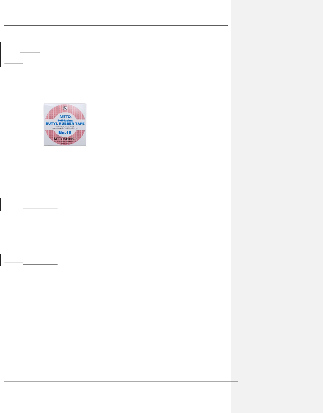
All connections are watertight, with Nitto No 15 self-amalgamating tape used on the
RF connections to ensure that water cannot get into the connector.
The sensors are installed in such a manner that they will not come off from operation,
and the sensor cables will not interfere with equipment operation. It is preferable that
sensor cables do not get very close to electric motor windings, which can generate
significant amounts of magnetic field, which may affect the sensor sensitivity.
The sensor electrical connections are waterproof.
The transient limiting of lightning, surges, and other transients coming from the mains
power is done within the power supply by the use of transient/surge absorbers. These
are connected line to line, as well as line to chassis ground. The characteristics of these
transient absorbers are as follows:
Part No
Varistor
Voltage (V)
Maximum
Allowable
Voltage
Clamping Voltage
At 8/20µs
Max (V) Ip (A)
Maximum Peak
Current at 8/20µs (A)
1 time 2 times
Panasonic
ERZ-V20D431
430
(387 to 473)
275Vac, 350 Vdc
745
5
800
600
710
10
1750
1250
710
25
3500
2500
710
25
3500
2500
710
50
6000
4500
710
100
10000
6500
Figure 1-1 Transient Protection Parameters, Line to Line and Line to Ground
The Continuous operating temperature of the gaskets are as follows:
<ADD GASKET COT INFORMATION HERE>
The Weir Group PLC Weir Industrial Gateway setup guide rev 0.5
Copyright © Weir Minerals Australia Ltd 2017. Commercial in Confidence. All rights reserved. Page 4 of 46
2 Transportation and Storage
2.1 Consignment receipt and unpacking
o Inspect the package for damaged or missing items upon delivery. All items
should be checked against the delivery note
o Note any damaged or missing items and inform the supplier and relevant
parties
2.2 Transportation Guidelines
o The gateway and its components are designed to be lifted and man-
transported without cranes or other lifting equipment
2.3 Storage
For long term storage, ensure connector caps are firmly secured on the all gateway
connectors
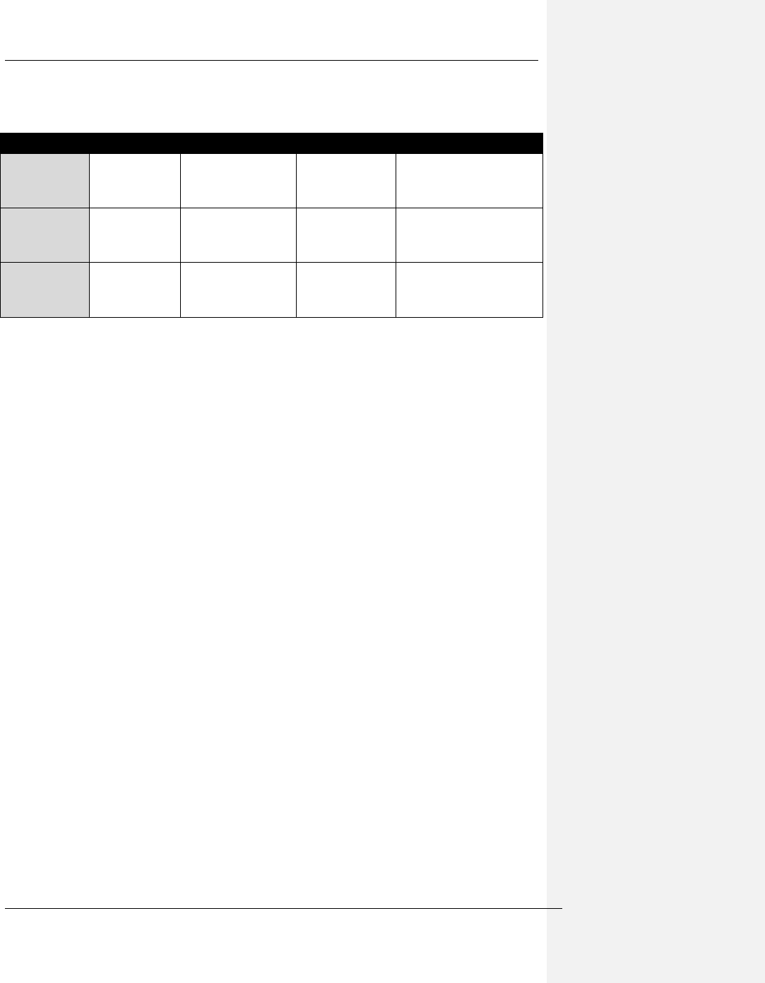
3 System components
A number of main components are common across many of the product implementations.
These are :
o Power Supply Module (PSM)
o Main Processor Module (MPM)
o Remote Signal Processor (RSP)
Name
Acronym
Description
Power Supply
Module
PSM
24Vdc 500W power
supply for MPM, able to
supply fully loaded
system at extremes of
environmental ratings
Main Processor
Module
MPM
Module that runs the
Node Engine software,
processes data &
connects to the
enterprise
The Weir Group PLC Weir Industrial Gateway setup guide rev 0.5
Copyright © Weir Minerals Australia Ltd 2017. Commercial in Confidence. All rights reserved. Page 5 of 46
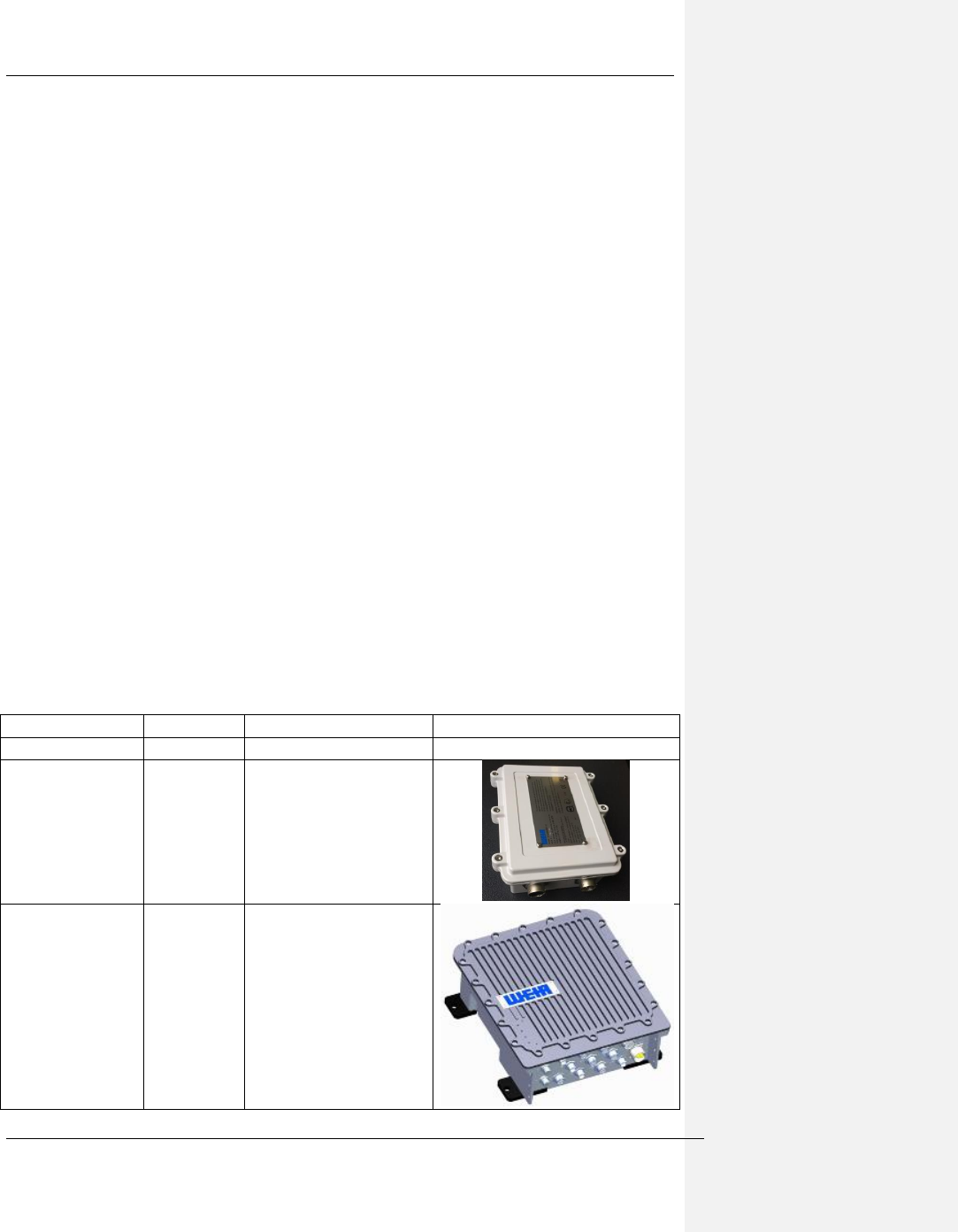
Remote Signal
Processor
RSP
Device that interfaces
with sensors on the
equipment
Junction Boxes
Various
A number of junction
boxes and cables are
used to connect the
RSP to sensors on the
equipment, example
shown to right
WiFi Antenna
(2.4GHz)
Default WiFi antenna
(2.4GHz) 6dB
Omnidirectional
(Mobilemark)
Cellular Antenna
Default Cellular band
Antenna 9dB
Omnidirectional
(Mobilemark)
WiFi Antenna
(2.4GHz/5GHz)
Dual Band Operation
(Laird)
The Weir Group PLC Weir Industrial Gateway setup guide rev 0.5
Copyright © Weir Minerals Australia Ltd 2017. Commercial in Confidence. All rights reserved. Page 6 of 46
Along with these are a range of standard cables that connect these main components to the
sensors on the equipment.
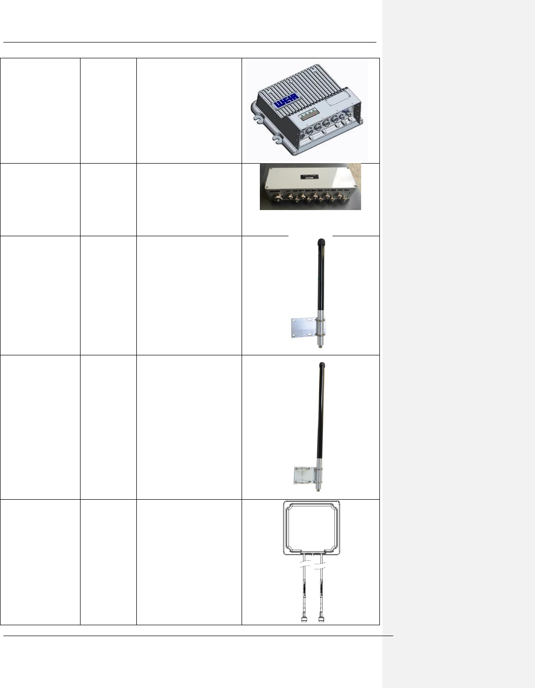
54 System architecture
The Weir Industrial Gateway MPM & RSP system is arranged in a modular manner shown in
the figure below.
Main Processor Module
(MPM)
Power Supply Box
(PB)
24VDC
RSP
RSP
RSP
RSP
Qpro
Sat/GPS
Sensor
Sensor
Sensor
Sensor
Sensor
Sensor
Sensor
Sensor
Sensor
Sensor
Sensor
Sensor
Sensor
Sensor
Sensor
Sensor
ECA_MR_nn
24VDC, LAN
ECA_RS_nn
Analog
ECA_MQ_01
24VDC, Serial
ECA_PM_01
24VDC
WIFI
Module
ECA_MW_01
POE
Figure 4-1 System diagram
o MPM can support 4 x RSPs directly wired via Ethernet
o PSM is rated to support MPM + 4 x RSPs + all other optional items
o Each RSP is located near a piece of equipment being monitored while the
MPM may be remotely located with a maximum of a 100m cable run. Option
to have RSP connected to the MPM via an external WiFi module but this
arrangement requires a local 24Vdc supply to the RSP.
o Qpro amd WiFi module are optional items and not covered in this guide
The Weir Group PLC Weir Industrial Gateway setup guide rev 0.5
Copyright © Weir Minerals Australia Ltd 2017. Commercial in Confidence. All rights reserved. Page 7 of 46
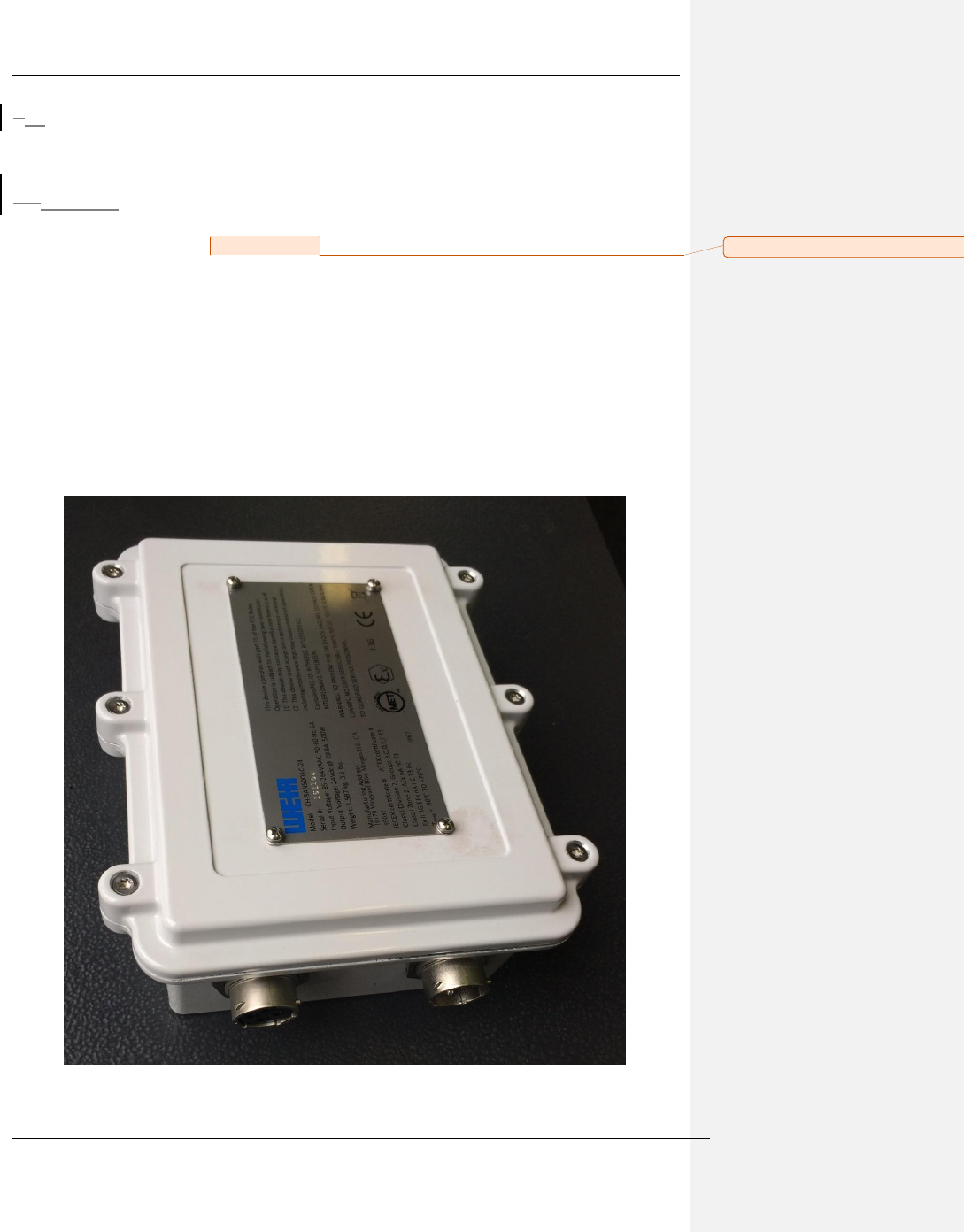
65 PSM – Power Supply Module
The PSM is a switch mode power supply that operates of mains AC power and provides the
24Vdc that the whole system operates from.
6.15.1 Parameters relevant to installation and operation
o Model # : SPSM-000001
o DELL SKU : IP67IPS500-24
o Supply : 90 to 264 VAC, 47 to 400 Hz
o Output: 20A@24Vdc (Nominal 500W)
o IP rating : 67
o IK rating : 09
o Hazloc : Certified for Class 1 Div 2 environment
o Temperature range (operating) : -30°C ≤ Tamb ≤ 70°C
o Mass : 1.587kg
o MTBF : > 500,000 hours
o Casing material : Powder coated die cast aluminium
o Mounting orientation : Connectors facing downwards
Figure 5-1 Iso view of PSM
Comment [CS1]: Is this a Sanmina part# ?
The Weir Group PLC Weir Industrial Gateway setup guide rev 0.5
Copyright © Weir Minerals Australia Ltd 2017. Commercial in Confidence. All rights reserved. Page 8 of 46
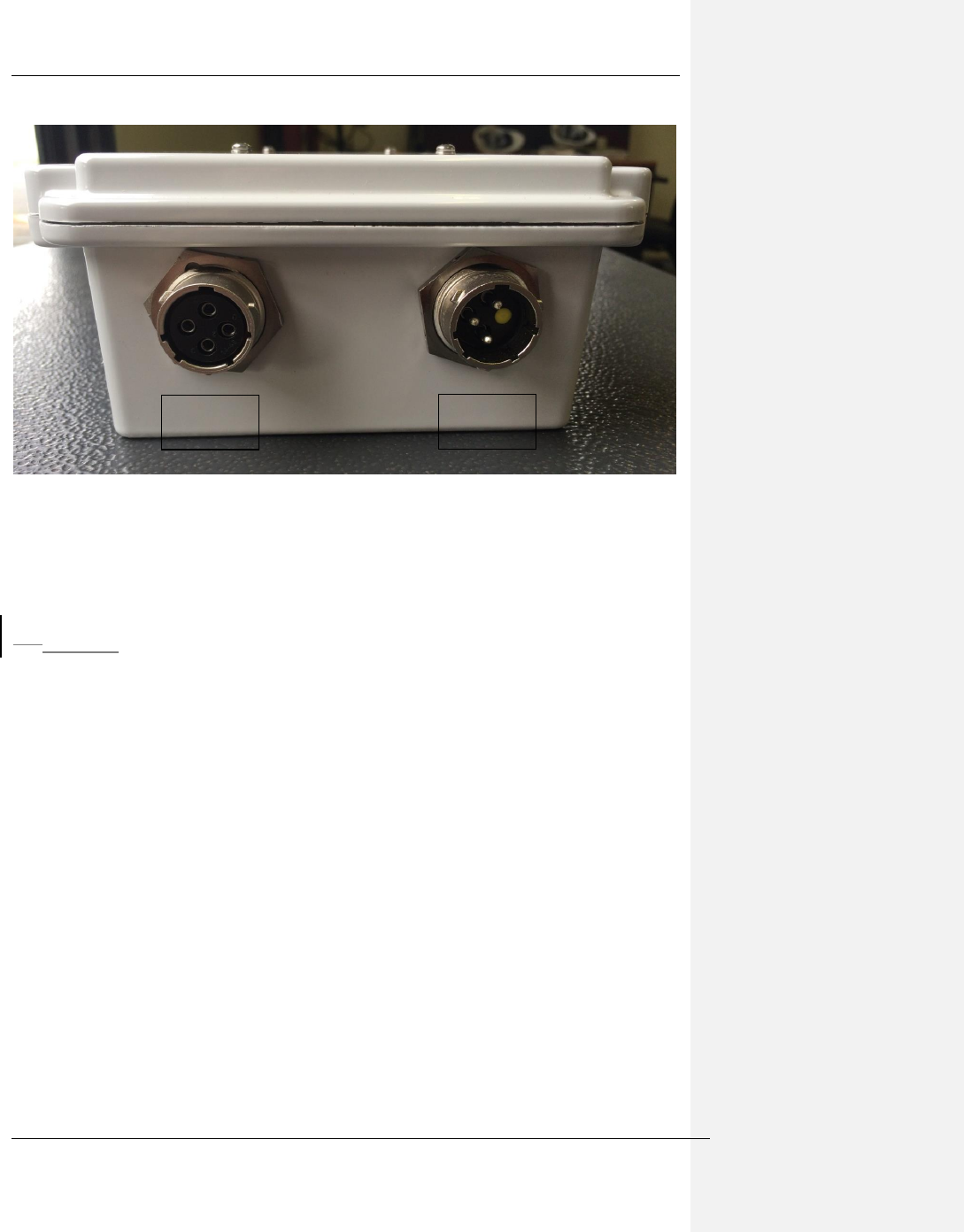
Figure 5-2 PSM Connectors
The cables provided with the power supply are as follows:
AC Cable: PN# LFS04876 connects to the 3 pin port marked "power in".
DC Cable: PN# LFS04875 connects to the 4 pin port marked "power out".
6.25.2 Installation
Physical installation of the PSM is covered in section 6.4. Electrical installation must include
a current limiting device (fuse or circuit breaker) rated to protect the AC supply cable
connected to J1. This circuit breaker should be rated to 15A.
J1 – AC
Power in
J2 DC
Power out
The Weir Group PLC Weir Industrial Gateway setup guide rev 0.5
Copyright © Weir Minerals Australia Ltd 2017. Commercial in Confidence. All rights reserved. Page 9 of 46
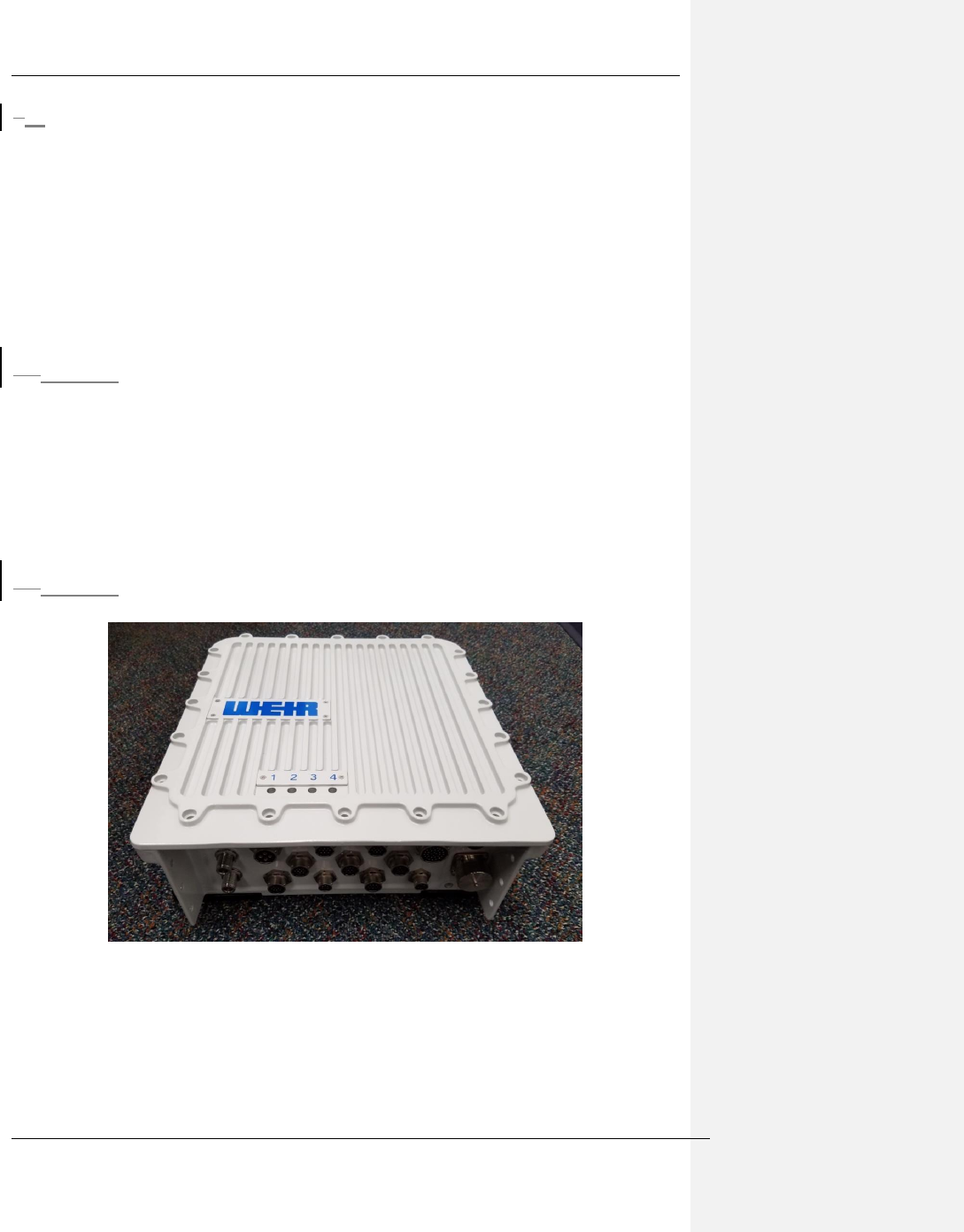
76 MPM – Main Processing Module
The primary functions of the MPM are:
- Run the Node Engine application(s) required for each piece of equipment
o Convert signals captured by the RSP or other devices into TAG Metrics
o Perform secure authentication with the Synertrex Enterprise
o Provide remote access mechanism to allow diagnosis and analysis of issues
on site
The MPM is housed in a rugged enclosure fitted with signal conditioning, data acquisition,
data processing and cloud interfacing systems.
7.16.1 Parameters relevant to installation and operation
o Supply : 14.6A@24Vdc
o IP rating : 66
o IK rating : 09
o Hazloc : Certified for Class 1 Div 2 environment
o Temperature range (operating) : -30°C ≤ Tamb ≤ 70°C
o Mass : 16.7 kg / 36.8 lb
o Casing material : Powder coating over allodyned aluminium
o Mounting orientation: On vertical plate/wall with all connectors facing down
7.26.2 Images
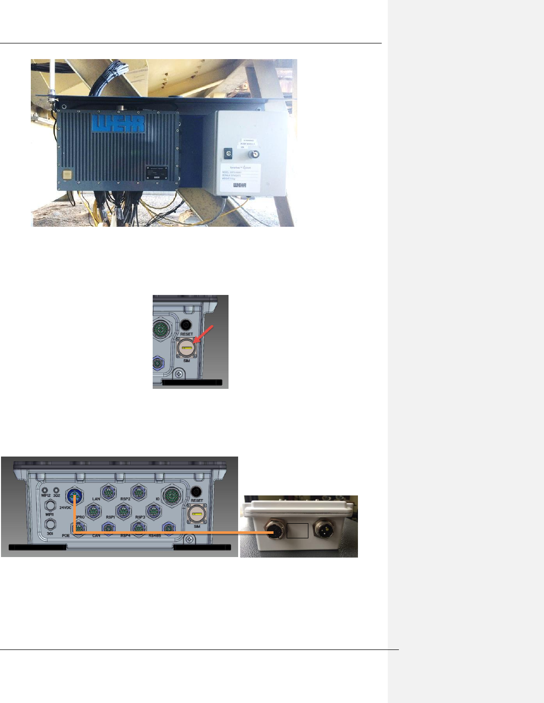
Figure 6-1 MPM perspective view (cables and protective shroud removed)
The Weir Group PLC Weir Industrial Gateway setup guide rev 0.5
Copyright © Weir Minerals Australia Ltd 2017. Commercial in Confidence. All rights reserved. Page 10 of 46
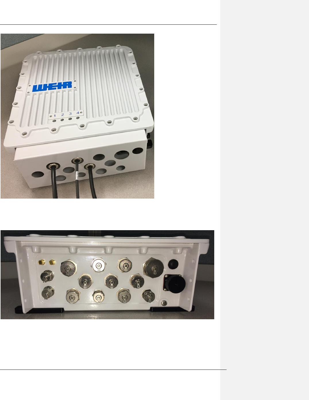
Figure 6-2 MPM with connector shroud installed
Connector shroud must be installed at all times once connectors are in place to prevent
slurry/mud etc getting onto the connectors AND to meet hazardous location standards.
Figure 6-3 MPM connector view - protective caps installed
Connector caps shown are to be left installed for all connectors without a cable assembly
attached. This is required for hazardous location approvals.
The Weir Group PLC Weir Industrial Gateway setup guide rev 0.5
Copyright © Weir Minerals Australia Ltd 2017. Commercial in Confidence. All rights reserved. Page 11 of 46
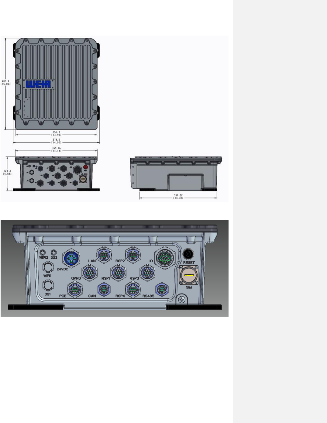
Figure 6-4 MPM External dimensions
Figure 6-5 Connector view
The Weir Group PLC Weir Industrial Gateway setup guide rev 0.5
Copyright © Weir Minerals Australia Ltd 2017. Commercial in Confidence. All rights reserved. Page 12 of 46
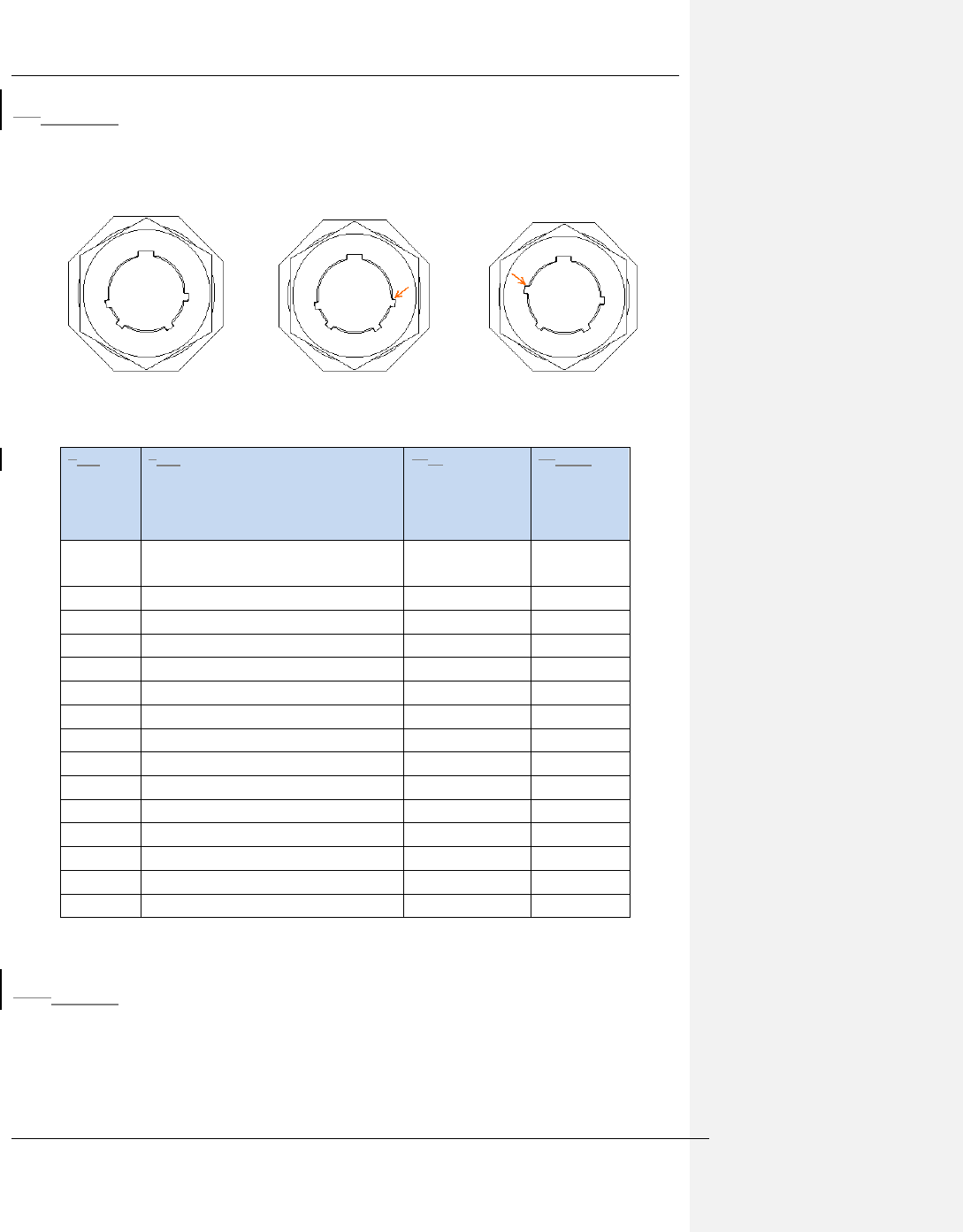
7.36.3 Connector Keying Types
The multi-conductor cables have three different keying types, which are shown below. One
of the tabs is moved in order to provide keying, this tab is shown with the orange arrow.
SNH SYH SWH
Figure 6-6 Connector Keying, View from MPM Connector
87 Exte
rnal
Nam
e
98 Description
109 Cable Part
Number
1110 Keyi
ng Type
If Used
Wifi 1
WiFi primary connector to EG5100
WiFi
CA120/195-XX
N/A
Wifi 2
WiFi connector to EG5100 WiFi
CA120/195-XC
N/A
3G 1
WWAN primary connector to EG5100
CA120/195-XX
N/A
3G 2
WWAN connector to EG5100
CA120/195-XC
N/A
Qpro
Qpro (GPS receiver) power and signal
LFS04869
SNH
POE
POE Lan port
LFS04870
SWH
LAN
LAN
LFS04870
SWH
RS485
RS485
LFS04880
SNH
CAN
CAN
LFS04872
SWH
RSP 1
RSP #1
LFS04873
SYH
RSP 2
RSP #2
LFS04873
SYH
RSP 3
RSP #3
LFS04873
SYH
RSP 4
RSP #4
LFS04873
SYH
24VDC
Power input
LFS04875
SNH
IO
Analog/Digital IO
LFS048734
SWH
Figure 6-7 - MPM connector names and locations
11.110.1 LED Indicators
There are 4 LEDs on the MPM front face. The status of these LEDs are as follows::
1.) Green LED 1 – Power
2.) Green LED 2 – System running
3.) Green LED 3 – Wi-Fi Good
4.) Green LED 4 – Enterprise connected.
The Weir Group PLC Weir Industrial Gateway setup guide rev 0.5
Copyright © Weir Minerals Australia Ltd 2017. Commercial in Confidence. All rights reserved. Page 13 of 46
11.210.2 Installation
11.2.110.2.1 Mounting plate & Hardware
The minimum recommended protective equipment for mounting this equipment would be as
follows: eye protection, gloves, hard hat, steel cap boots, long sleeves and trousers. Danger
tape to cordon off area below if installing at height is also recommended.
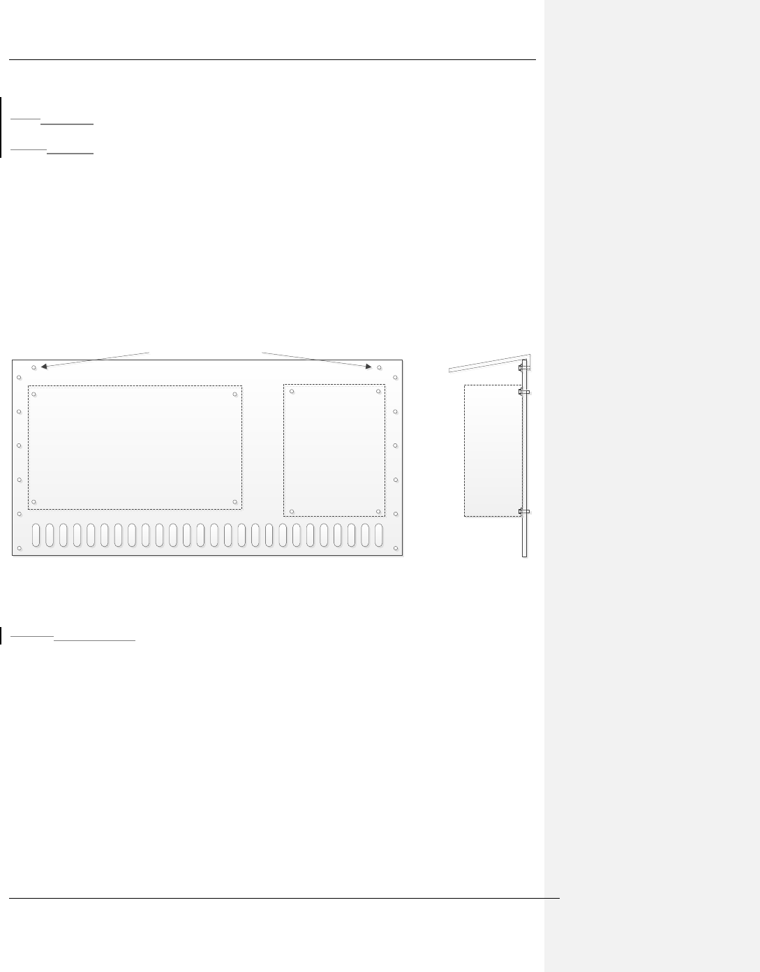
The mounting of the MPM, RSP, and power supply needs to be customized to the particular
system that it is intended for. In general a mounting plate made of 16 guage sheet steel
would be sufficient to provide adequate strength. A representative diagram of a mounting
plate is provided below:
Equipment Module
Equipment Module Power Supply
Power Supply
Weather protector attachment
Weather protector attachment Weather protector
Weather protector
SIDE VIEW
SIDE VIEW
FRONT VIEW
FRONT VIEW
Figure 6-8 MPM & PSM generic mounting plate
11.2.1.110.2.1.1 Installation
1. The mounting plate must be mounted in the vertical plane and as level as possible.
2. Fasten or weld the mounting plate to a structure near the equipment with the
following conditions:
a. No more than 50m from the equipment (100m cable run)
b. Attach to a solid structure, relatively free from vibration, ensuring that it is
capable of supporting the combined mass of approximately 30kg and the
additional loading from any vibration.
c. Ensure there is sufficient clearance (~10mm) for bolts to protrude through the
rear of the plate
3. A sun visor/slurry shield is recommended to be added to the mounting plate, which is
shown in the diagram.
The Weir Group PLC Weir Industrial Gateway setup guide rev 0.5
Copyright © Weir Minerals Australia Ltd 2017. Commercial in Confidence. All rights reserved. Page 14 of 46
11.2.210.2.2 MPM & PSM
11.2.2.110.2.2.1 Equipment and materials required
• Tools
o Allen keys, wrench/spanner to cover sizes 6, 8 & 10mm cap screws and nuts
o Side cutters/scissors or similar to cut self-amalgamating tape
• Consumables
o Self-amalgamating tape : Nitto No 15
o AC supply cable : PN# TBD (note that the mains cable has open wires to
allow connection to a fuse box or the appropriate connector to suit the
customers power outlet)
o DC out cable : DELL SKU: LFS04875-012M00
o 4 - M5 self tapping screws for mounting
• Provisioned SIM card
11.2.2.210.2.2.2 Hazards
- The MPM is relatively heavy (16kg) and requires 2 people to transport and assist
each other during mounting.
- If dropped from height this module is a potentially deadly hazard hence the area
below the installation must be cordoned off with danger tape.
- Mains power is a potentially deadly hazard and hence must only be modified or
connected by a certified Electrician.
11.2.2.310.2.2.3 Installation
1. Ensure the serial number on the MPM and PSM correspond with the equipment to be
monitored and installation location
2. Ensure the protective caps remain on the MPM & PSM connectors until cables are
installed
3. Install the MPM & PSM in the arrangement shown below in Figure 6.8. Ensure a
fastener is used for each mounting hole. The mounting of the PSM is done using M5
self tapping screws.
The Weir Group PLC Weir Industrial Gateway setup guide rev 0.5
Copyright © Weir Minerals Australia Ltd 2017. Commercial in Confidence. All rights reserved. Page 15 of 46
Figure 6-9 - MPM & PSU installed on mounting plate
4. If SIM card has not been installed, insert this now into J15 on the MPM. The
protective shroud needs to be removed to do this (needs Torx T27 driver). Be sure to
re-install the protective cap afterwards.
Figure 6-10 SIM card receptacle in MPM
5. Connect 24Vdc power lead (PN# LFS04875-012M00) from PSM J2 into DC power
input port (J14) on MPM
Figure 6-11 24Vdc power connection from PSM to MPM
6. Ensure the customer mains outlet is either isolated or turned off and locked
7. Connect the mains power lead from the customer power outlet to the AC input port J1
on the PSM using cable PN# LFS04876.
J2
The Weir Group PLC Weir Industrial Gateway setup guide rev 0.5
Copyright © Weir Minerals Australia Ltd 2017. Commercial in Confidence. All rights reserved. Page 16 of 46
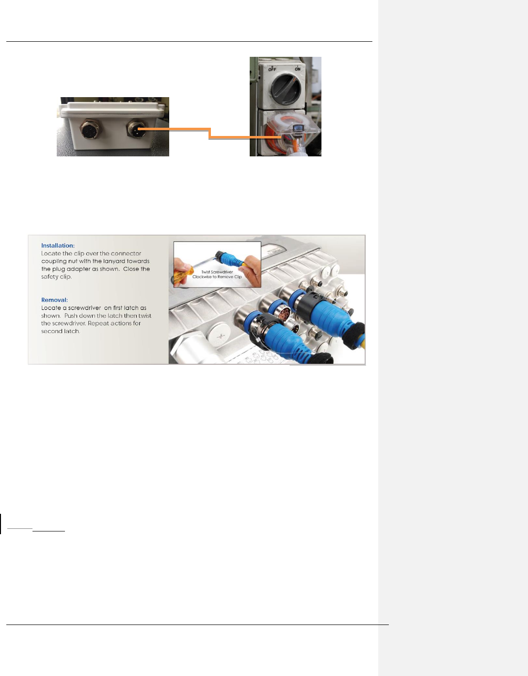
Figure 6-12 Mains AC power connection to PSM
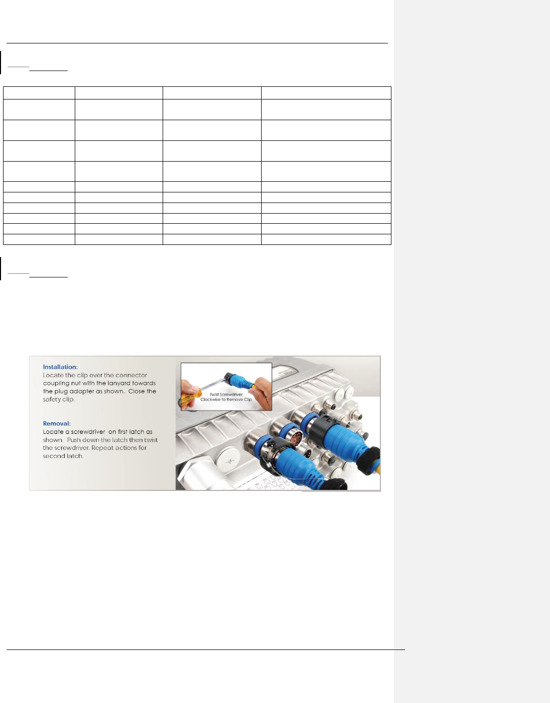
8. Locking clips need to be installed on the power supply connectors for hazardous
location compliance. These locking clips shall only be removed by qualified service
personnel. The installation of these clips is as follows:
Figure 6-13 Installation of Locking Clips
WARNING: EXPLOSION HAZARD. DO NOT CONNECT OR DISCONNECT CABLES
WHEN ENERGIZED IN A HAZARDOUS LOCATION ENVIRONMENT.
AVERTISSEMENT: RISQUE D'EXPLOSION. NE PAS CONNECTER OU DÉCONNECTER
DES CÂBLES QUI ENERGISES DANS UN ENVIRONNEMENT DE LOCALISATION
DANGEREUSE.
9. Protective earth grounding of the system is provided by the earth ground connection
from the power supply AC cable, and connection of the enclosures of the MPM and
PSM to earth ground is optional.
11.2.310.2.3 Hazardous Location Requirements
The enclosure of the power supply and the MPM will need to be grounded to earth ground
according to local building codes for hazardous location use. The back side of the power
supply is bare metal, allowing it to be grounded to the mounting plate when it is bolted in
place. The mounting plate will need to have no coating where the power supply is installed
in order to provide electrical conductivity.
The Weir Group PLC Weir Industrial Gateway setup guide rev 0.5
Copyright © Weir Minerals Australia Ltd 2017. Commercial in Confidence. All rights reserved. Page 17 of 46
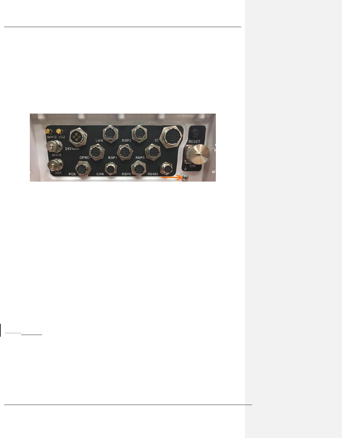
The MPM has an M6 sized external grounding screw for protective earth grounding.
Insulated 10AWG wiring is needed to connect this grounding screw to the mounting plate,
along with the use of M6 sized ring connectors for 10AWG wire. The connection to the
mounting plate should be made using a lock washer or lock nut to ensure that the connection
cannot loosen from vibration. If this mounting plate is not directly connected to earth ground
through the machinery then the mounting plate will also need to be grounded to earth with
the use of 10AWG wire and ring connectors.
The location of the grounding screw for the MPM is as follows:
Figure 6-14 Location of Protective Earth Grounding on MPM
The connector shroud must be installed at all times once connectors are in place to prevent
slurry/mud etc getting onto the connector threads AND to meet the standards certified
against for Hazardous Location operation.
WARNING: THE POE AND 24 AUX PORTS SHALL NOT BE USED IN HAZARDOUS
LOCATION AREAS.
WARNING: EXPLOSION HAZARD. DO NOT CONNECT OR DISCONNECT CABLES
WHEN ENERGIZED IN A HAZARDOUS LOCATION ENVIRONMENT.
AVERTISSEMENT: LE POE ET LES 24 PORTES AUX AUTRES NE SONT PAS UTILISÉS
DANS LES ZONES DE LOCALISATION DANGEREUSES.
AVERTISSEMENT: RISQUE D'EXPLOSION. NE PAS CONNECTER OU DÉCONNECTER
DES CÂBLES QUI ENERGISES DANS UN ENVIRONNEMENT DE LOCALISATION
DANGEREUSE.
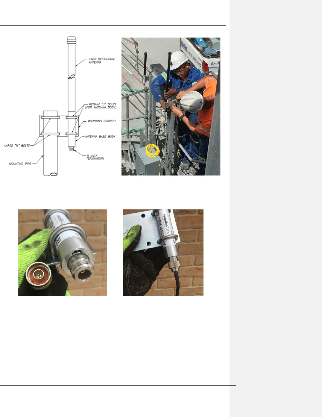
11.2.410.2.4 Antenna
Up to four Antennae may be utilised per MPM :
- Cellular (default)
- Wifi (default)
- Dual Band WiFi (optional)
- GPS module (optional)
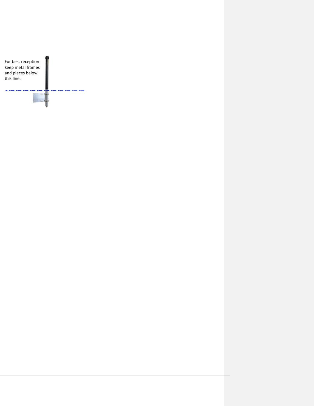
The installation position and orientation are crucial to the optimal operation of an antenna –
- Ensure it is mounting in a vertical orientation
The Weir Group PLC Weir Industrial Gateway setup guide rev 0.5
Copyright © Weir Minerals Australia Ltd 2017. Commercial in Confidence. All rights reserved. Page 18 of 46
- Install away from metal objects such as walls, beams, posts etc
- If mounted on a post, the radiating section of the antenna (above aluminium base)
needs to be level or above the post
11.2.4.110.2.4.1 Equipment and materials required
• Minimum recommended PPE:
o eye protection, gloves, steel cap boots, hard hat, long sleeves and trousers,
danger tape to cordon off area below if installing at height
• Spanner/wrench :
o 7/16” / 11mm (open ended)
• Cellular antenna
o OD-850 (Mobilemark) : Longer antenna (comes with mounting bracket)
o Cable assembly : CA120/195-XX (Mobile Mark)
• Wi-Fi antenna (Default)
o OD-2400 (Mobilemark) shorter antenna
o Cable assembly : CA120/195-XX (Mobile Mark)
• Wi-Fi antenna (Optional)
o Laird PVD24515-DE1
11.2.4.210.2.4.2 Hazards
- If dropped from height the antenna(e) are a potential hazard for people below
- Working from height while installing the antenna(e) is a hazard hence standard
procedures to work at height should be followed to reduce risks.
11.2.4.310.2.4.3 Installation
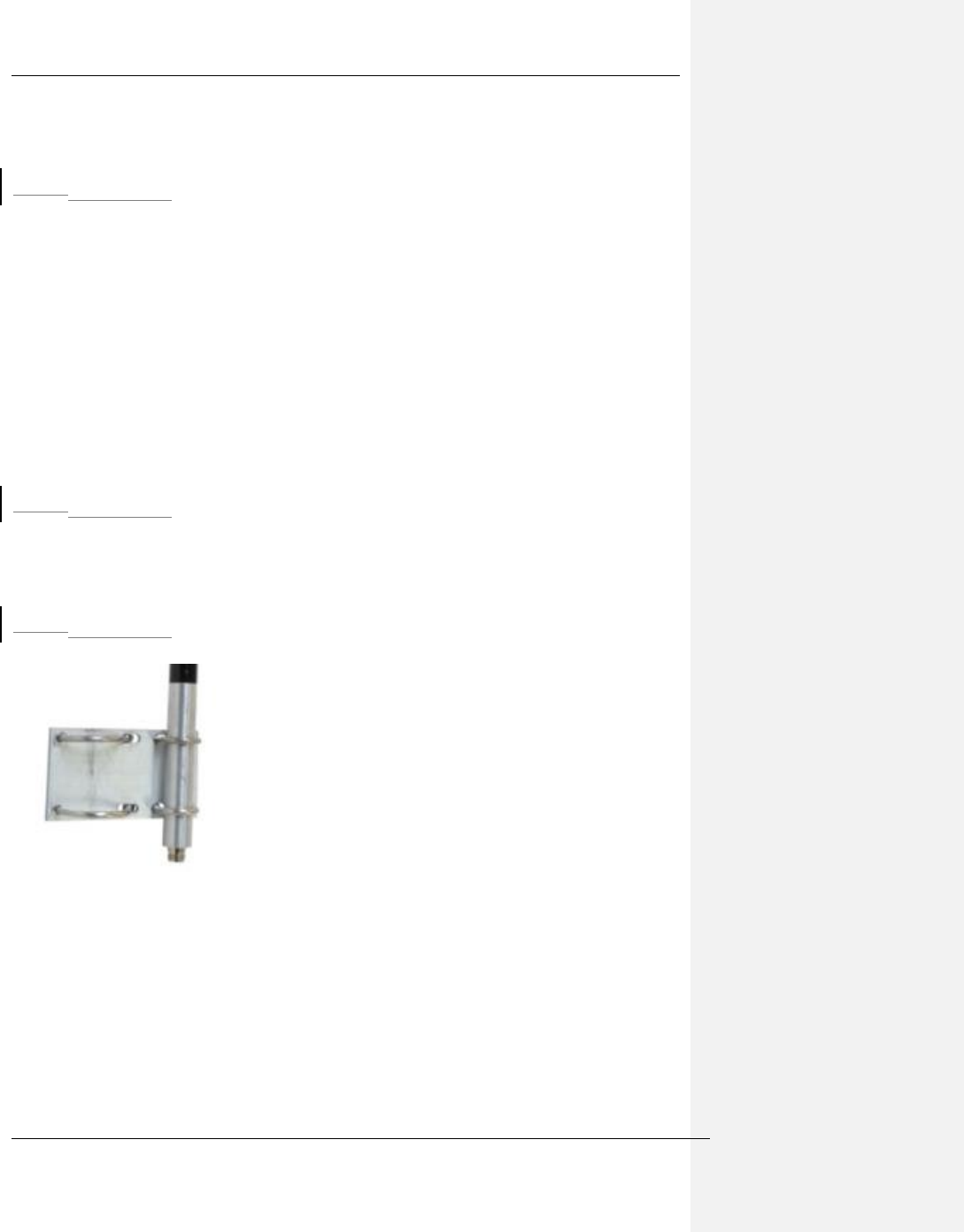
1. Mount the antenna to the supplied plate using the hardware provided
Figure 6-15 Antenna mount attached
2. Tighten the nuts and lock nuts (thinner of the two) on the two smaller U-Bolts
3. Mount the plate with antenna to your mast/pole using two larger U-bolts
The Weir Group PLC Weir Industrial Gateway setup guide rev 0.5
Copyright © Weir Minerals Australia Ltd 2017. Commercial in Confidence. All rights reserved. Page 19 of 46
Figure 6-16 Installation of Antenna(e)
4. Remove the red protective cap and connect the antenna cable to the antennas coax
connector
Figure 6-17 Antenna with and without cable attached
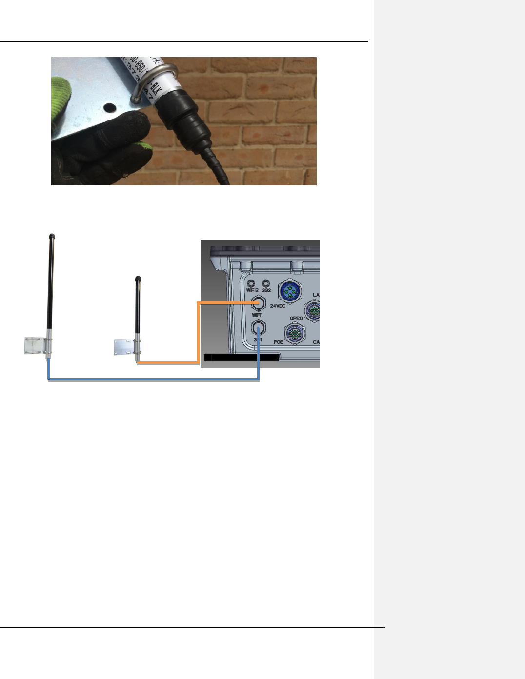
5. Wrap connector interface with self-amalgamating tape to protect from slurry, etc.
This is required for hazardous location compliance.
The Weir Group PLC Weir Industrial Gateway setup guide rev 0.5
Copyright © Weir Minerals Australia Ltd 2017. Commercial in Confidence. All rights reserved. Page 20 of 46
Figure 6-18 Antenna connector wrapped in protective tape
6. Connect the other end of the cable(s) to the MPM Antenna ports
Figure 6-19 Schematic of Wifi and Cellular antennae connections to MPM
For best results:
- Mount the antenna as high up as the cable length / location permits, with optimal line-
of-sight to the receiver
- Attach to a pipe / mast if possible
- If mounted near other antenna, maintain a separation of at least 300mm (~1 foot)
- Avoid placement near close metal objects as unpredictable disturbance can result
- Avoid placing on the side of a building or tower as directivity can be expected
- Mount antenna facing vertically for proper polarization and avoid mounting up-side
down as the antenna will not drain correctly.
Wifi
Cellular
The Weir Group PLC Weir Industrial Gateway setup guide rev 0.5
Copyright © Weir Minerals Australia Ltd 2017. Commercial in Confidence. All rights reserved. Page 21 of 46
The Weir Group PLC Weir Industrial Gateway setup guide rev 0.5
Copyright © Weir Minerals Australia Ltd 2017. Commercial in Confidence. All rights reserved. Page 22 of 46
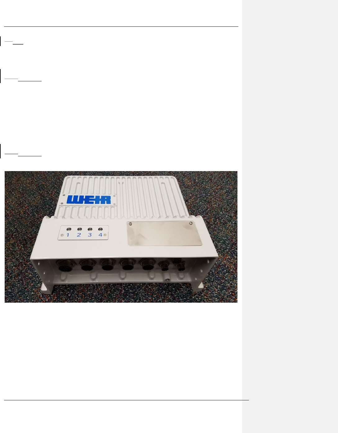
1211 RSP – Remote Signal Processor
The RSP is housed in a rugged enclosure fitted with signal conditioning, data acquisition and
data processing systems.
12.111.1 Parameters relevant to installation and operation
- Supply : 4.2A@24Vdc
- IP rating : 66
- IK rating : 09
- Hazloc : Certified for Class 1 Div 2 environment
- Temperature range (operating) : -30°C ≤ Tamb ≤ 70°C
- Mass : 10.5kg / 23.1 lb
- Casing material : Powder coated die cast aluminium
- Mounting orientation: On vertical plate/wall with all connectors facing down
12.211.2 Images
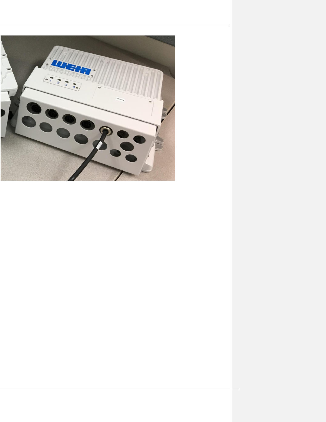
Figure 11-1 RSP Overview
The Weir Group PLC Weir Industrial Gateway setup guide rev 0.5
Copyright © Weir Minerals Australia Ltd 2017. Commercial in Confidence. All rights reserved. Page 23 of 46
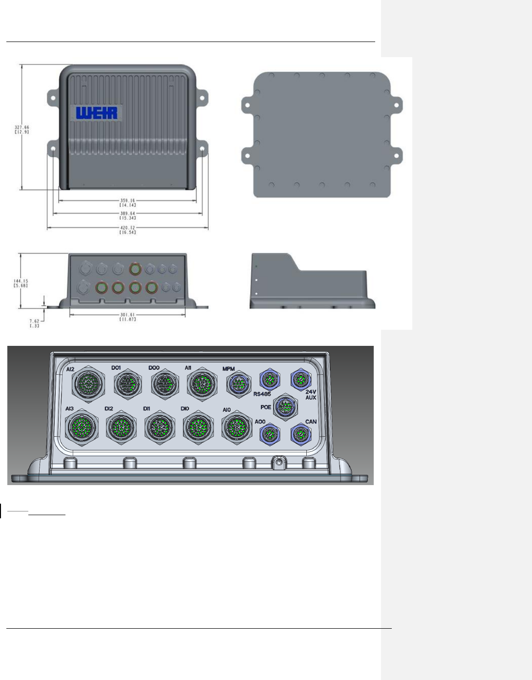
Figure 11-2 RSP shown with connector shield installed
Connector shroud must be installed at all times once connectors are in place to prevent
slurry/mud etc getting onto the connector threads AND to meet the standards certified
against for Hazardous Location operation.
The Weir Group PLC Weir Industrial Gateway setup guide rev 0.5
Copyright © Weir Minerals Australia Ltd 2017. Commercial in Confidence. All rights reserved. Page 24 of 46
Figure 11-3 RSP Physical dimensions
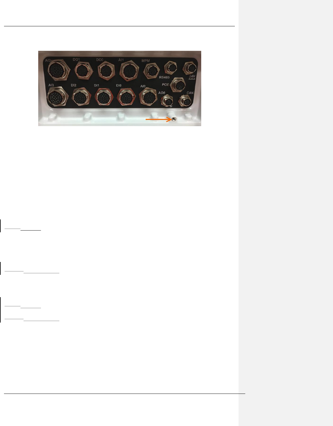
Figure 11-4 RSP Connector layout and descriptions
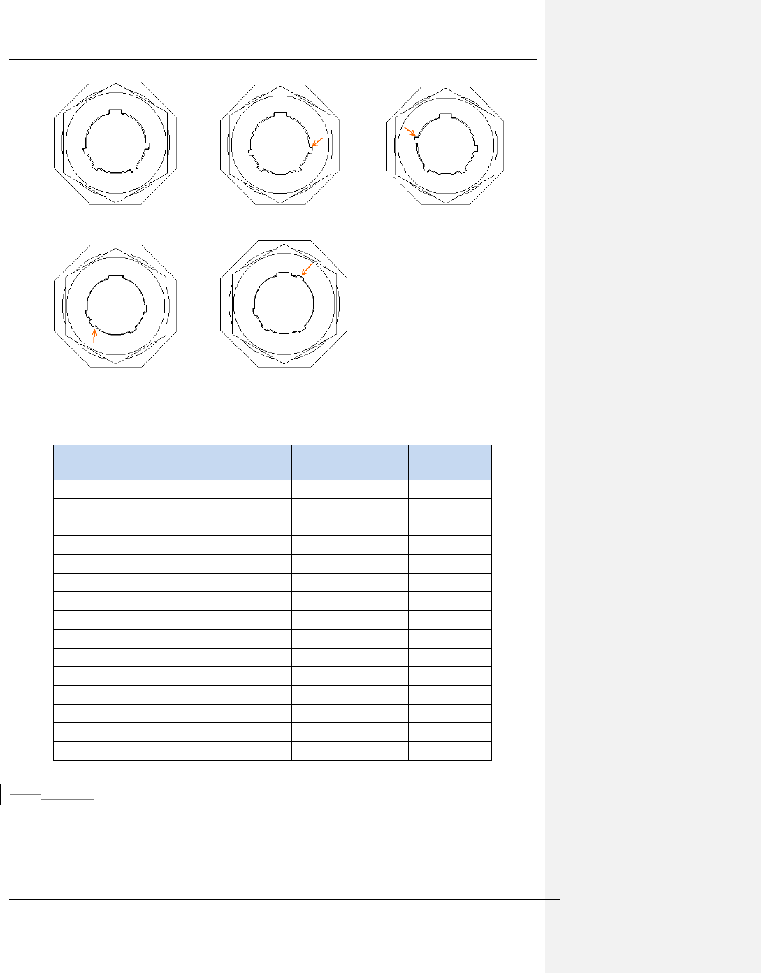
12.311.3 Connector Keying Types
The multi-conductor cables have three different keying types, which are shown below. One
of the tabs is moved in order to provide keying, this tab is shown with the orange arrow.
The Weir Group PLC Weir Industrial Gateway setup guide rev 0.5
Copyright © Weir Minerals Australia Ltd 2017. Commercial in Confidence. All rights reserved. Page 25 of 46
SNH SYH SWH
SXH SZH
Figure 11-5 Connector Keying, View from RSP Connector
External
Name
Description
Cable Part
Number
Keying Type
If Used
24V Aux
Auxiliary 24V power input
LFS04897
SXH
RS485
RS485/RS232 input
LFS04880
SNH
POE
POE port
LFS04870
SWH
CAN
Can bus port
LFS04872
SWH
MPM
Main MPM connector
LFS04873
SYH
AO0
Analog Output Bank 0
No Application
SZH
AI0
Analog Input Bank 0
LFS05179
SNH
AI1
Analog Input Bank 1
LFS05179
SNH
DO0
Digital Output Bank 0
LFS04879
SNH
DO1
Digital output Bank 1
LFS04879
SNH
DI0
Digital Input Bank 0
LFS04878
SWH
DI1
Digital Input Bank 1
LFS04878
SWH
DI2
Digital Input Bank 2
LFS04878
SWH
AI2
Analog input bank 2
LFS04877
SNH
AI3
Analog input bank 3
LFS04877
SNH
Figure 11-6 RSP Connector port descriptions
12.411.4 LED Indicators
There are 4 LEDs on the MPM front face. The status of these LEDs are as follows::
5.) Green LED 1 – Power
6.) Green LED 2 – System running
7.) Green LED 3 – MPM Communication Status
The Weir Group PLC Weir Industrial Gateway setup guide rev 0.5
Copyright © Weir Minerals Australia Ltd 2017. Commercial in Confidence. All rights reserved. Page 26 of 46
8.) Green LED 4 – I/O Status
12.511.5 Installation
This section covers the generic installation process for the RSP. It is important to note that
product specific installation such as sensors, junctions boxes etc will only be covered
generically and product specific instructions are covered in the IOM Manual.
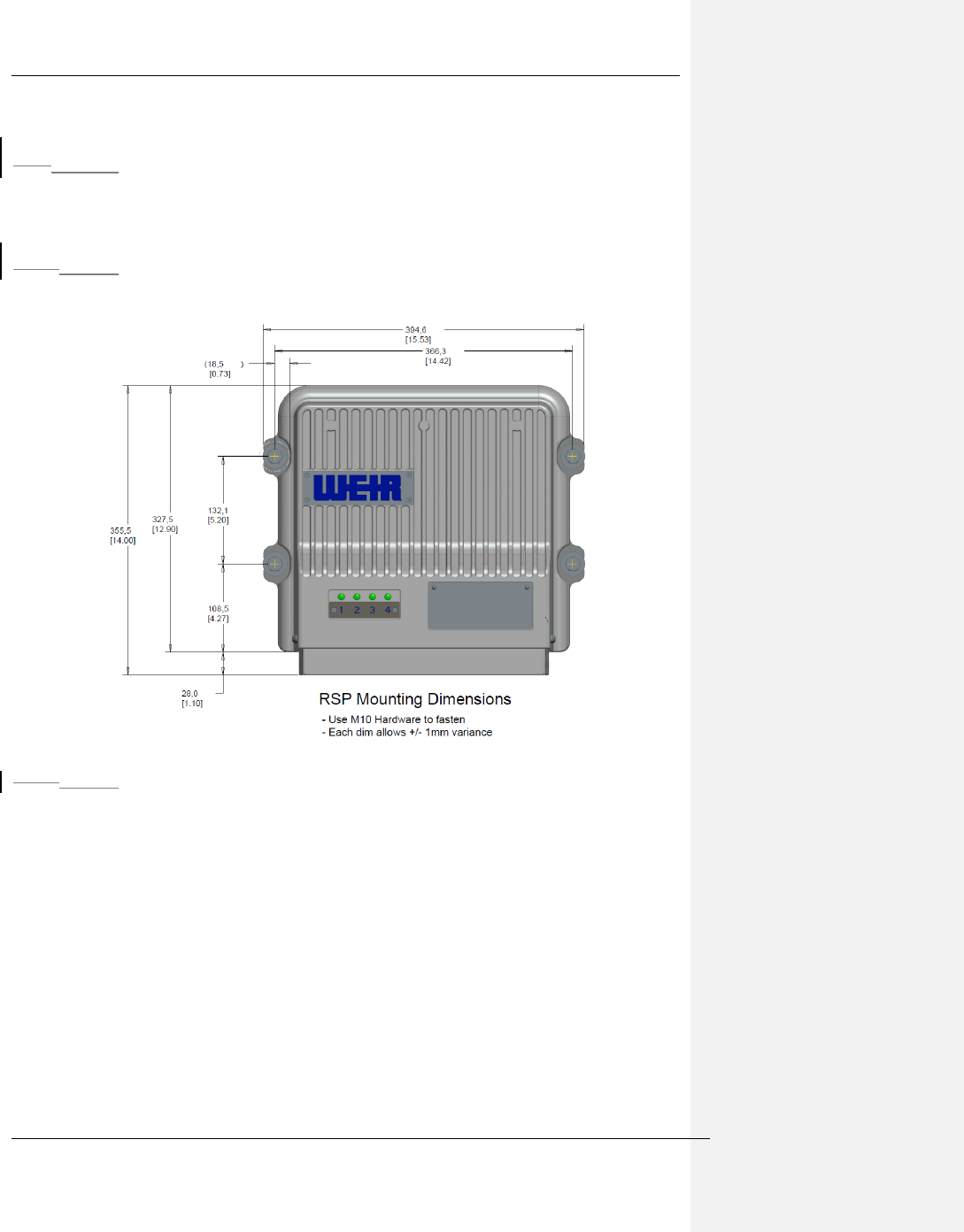
12.5.111.5.1 Physical mounting
The mounting dimensions are as follows. Use M10 bolts to fasten the RSP to the
mounting location.
Figure 11-7 RSP Mounting Dimensions
12.5.211.5.2 Hazardous Location Compliance
The enclosure of the RSP will need to be grounded to earth ground according to local
building codes for hazardous location use. The RSP has an M6 sized external grounding
screw for protective earth grounding. Insulated 10AWG wiring is needed to connect this
grounding screw to the mounting plate, along with the use of M6 sized ring connectors for
10AWG wire. The connection to the mounting plate should be made using a lock washer or
lock nut to ensure that the connection cannot loosen from vibration. If this mounting plate is
not directly connected to earth ground through the machinery then the mounting plate will
also need to be grounded to earth with the use of 10AWG wire and ring connectors.
The Weir Group PLC Weir Industrial Gateway setup guide rev 0.5
Copyright © Weir Minerals Australia Ltd 2017. Commercial in Confidence. All rights reserved. Page 27 of 46
The location of the grounding screw for the RSP is as follows:
Figure 11-8 Location of Protective Earth Grounding on RSP
The connector shroud must be installed at all times once connectors are in place to prevent
slurry/mud etc getting onto the connector threads AND to meet the standards certified
against for Hazardous Location operation.
WARNING: EXPLOSION HAZARD. DO NOT CONNECT OR DISCONNECT CABLES
WHEN ENERGIZED IN A HAZARDOUS LOCATION ENVIRONMENT.
AVERTISSEMENT: RISQUE D'EXPLOSION. NE PAS CONNECTER OU DÉCONNECTER
DES CÂBLES QUI ENERGISES DANS UN ENVIRONNEMENT DE LOCALISATION
DANGEREUSE.
12.5.311.5.3 Protective Earth Grounding for Non Hazardous Locations
Protective earth grounding of the system is provided by the earth ground connection from the
power supply AC cable, and connection of the enclosures of the RSP to earth ground is
optional.
12.5.3.111.5.3.1 Hazards
The RSP may be difficult to mount without the assistance of a second person; there is a
significant risk of dropping the unit without help. This could be a significant hazard for
bystanders if installing at height.
12.5.411.5.4 Connection to MPM
12.5.4.111.5.4.1 Equipment & materials required
Recommended minimum PPE
o Gloves, long sleeve shirt, trousers, eye protection
MPM to RSP Ethernet + power cable :
o 5m : SKU# LFS04873-015M00
o 20m : SKU# LFS04873-0120M00 TBC
o 50m : SKU# LFS04873-0150M00 TBC
MPM with spare RSP port
The Weir Group PLC Weir Industrial Gateway setup guide rev 0.5
Copyright © Weir Minerals Australia Ltd 2017. Commercial in Confidence. All rights reserved. Page 28 of 46
Tools required to remove and replace slurry guards
o Torx T27 driver
12.5.4.211.5.4.2 Hazards
No direct hazards of note
12.5.4.311.5.4.3 Installation
1. Run the cable between the MPM and RSP
2. RSP : Remove connector shroud
Images needed showing screw locations
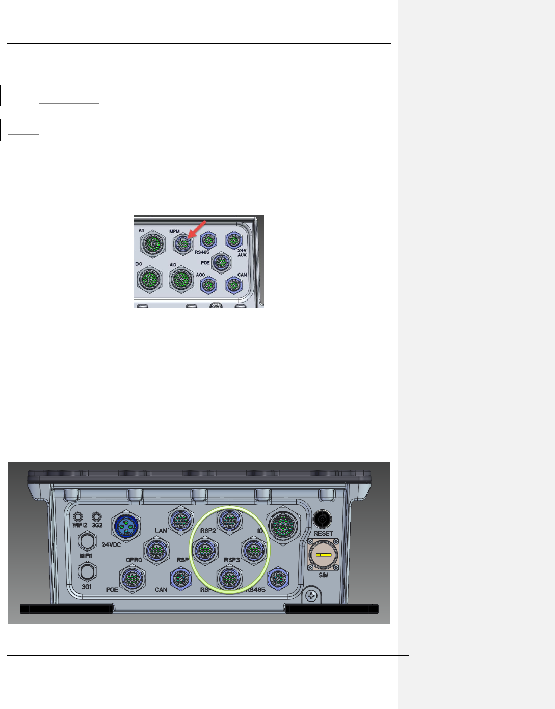
3. RSP : Remove the connector cap from J5
Figure 11-9 MPM Comms + power connector on RSP
4. RSP : Pass the MPM -> RSP comms + power cable through the hole in the shroud
associated with J5 and make the connection by pushing and turning the bayonet
fitting.
5. RSP : Ensure that all other connectors not being utilised have their protective caps
installed
6. RSP : Re-install the connector shroud per Fig 7.2
7. MPM: Remove the connector shroud, ensuring that the retaining screws are secured
ie do not lose these (no spares are shipped)
8. MPM: Feed the MPM<->RSP cable through the shroud hole associated with the port
being used for this RSP ie one of the four shown below
Figure 11-10 RSP comms + power connectors on MPM
The Weir Group PLC Weir Industrial Gateway setup guide rev 0.5
Copyright © Weir Minerals Australia Ltd 2017. Commercial in Confidence. All rights reserved. Page 29 of 46
9. MPM: Mate the connectors with a push and twist motion (bayonet style)
10. MPM: Reinstall the shroud
11. MPM: Turn on power to the MPM
12. MPM: Confirm that the following LEDs are lit
a. LED 1 – power
b. LED 2 – System running
13. RSP: Confirm that the following LEDs are lit
a. LED 1 – power
b. LED 2 – System running
14. If all above LEDs are lit, the configuration process may begin, if not contact the
Synertrex Operations team for assistance with troubleshooting and/or refer to the
troubleshooting guide within the IOM Manual.
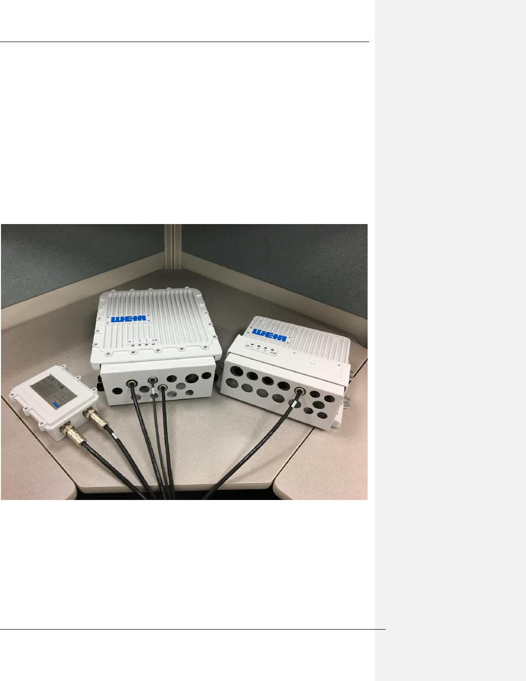
Figure 11-11 PSM, MPM and RSP connected
The Weir Group PLC Weir Industrial Gateway setup guide rev 0.5
Copyright © Weir Minerals Australia Ltd 2017. Commercial in Confidence. All rights reserved. Page 30 of 46
1312 Junction boxes and cables
The RSP has a generic signal interface designed to support a wide range of product types.
Therefore to match the RSP to any particular product a specific set of cables, junction boxes
and sensors are needed.
The complete list of junction box types and how they connect to the RSP is described in this
section.
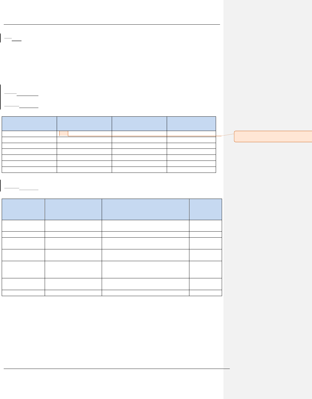
13.112.1 List of cables
13.1.112.1.1 Connecting to RSP
Description
Part #
RSP mating
connectors
Junction box
connector type
High speed Analog input
TBD
AI2, AI3
32pin
Low speed Analog input
TBD
AI0, AI1
32 pin
Digital Input
TBD
DI0, DI1, DI2
19 pin
Digital output
TBD
DO0, DO1
19 pin
Analog Output
TBD
AO
TBD
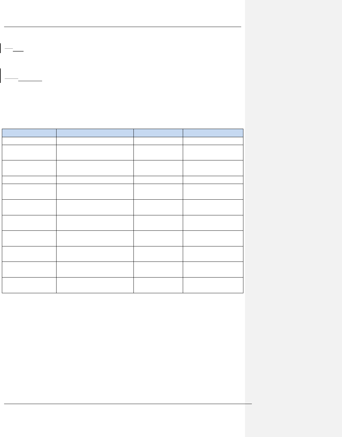
13.1.212.1.2 Junction Box to sensor
Sensor type
Sensor connector
Cable Part number (example
where XX is length in m)
Lengths
available
(m)
Gland water flow
meter
M12x1 4 pin
IndProx_8_DigitalInJB_Cable_XXm
10, 20
Inductive Prox
M12x1 4 pin
IndProx_8_DigitalInJB_Cable_XXm
10, 20
Uniaxial
accelerometer
2 pin Amphenol
MS3106F10SL-4S
Accel_8_AnalogInJB_Cable_XXm
3, 6, 10, 20
Triaxial
accelerometer
4 pin Amphenol
PT06W8-4S(SR)
TriAccel_8_AnalogInJB_Cable_XXm
10, 20
Glandwater
pressure
transducer
6 pin Amphenol
PT06W10-6S(SR)
GlandPressure_8_AnalogJB_Cable_XXm
10
Temperature RTD
3 pin Marlin
1211U 3 PIN MINI JACK
2, 5, 10
Comment [CS2]: Require part numbers from
Sanmina
The Weir Group PLC Weir Industrial Gateway setup guide rev 0.5
Copyright © Weir Minerals Australia Ltd 2017. Commercial in Confidence. All rights reserved. Page 31 of 46
13.212.2 List of Junction Boxes
Description
Part#
RSP cable(s)
Sensor cables supported
4 Channel AI
4_AnalogIn_JB
32 <-> 24 pin (part# TBD)
32 <-> 32 pin (part# TBD)
All single channel analog
8 Channel AI
8_AnalogIn_JB
32 <-> 24 pin (part# TBD)
32 <-> 32 pin (part# TBD)
All single channel analog
4 Tri + 4 GP AI
4Tri-4GP_AnalogIn_JB
32 <-> 32 pin (part# TBD)
2 cables required
4 x Tri-axial Accelerometers + 4 x
single channel analog
3 Tri + 7 GP AI
3Tri_7GP_AnalogIn_JB
32 <-> 32 pin (part# TBD)
2 cables required
3 x Tri-axial Accelerometers + 7 x
single channel analog
4 x DI
4_DigIn_JB
19 <->19 pin (part# TBD)
IndProx_8_DigitalInJB_Cable_XXm
8 x DI
8_DigIn_JB
19 <->19 pin (part# TBD)
IndProx_8_DigitalInJB_Cable_XXm
4 x DO
4_DigOut_JB
19 <->19 pin (part# TBD)
TBD
8 x DO
8_DigOut_JB
19 <->19 pin (part# TBD)
TBD
2 x AO
TBD
13.312.3 Installation
This section covers the generic installation process for the junction boxes.
Locking clips need to be installed on the power supply connectors for hazardous location
compliance. These locking clips shall only be removed by qualified service personnel. The
installation of these clips is as follows:
Figure 12-1 Installation of Locking Clips
WARNING: EXPLOSION HAZARD. DO NOT CONNECT OR DISCONNECT CABLES
WHEN ENERGIZED IN A HAZARDOUS LOCATION ENVIRONMENT.
AVERTISSEMENT: RISQUE D'EXPLOSION. NE PAS CONNECTER OU DÉCONNECTER
DES CÂBLES QUI ENERGISES DANS UN ENVIRONNEMENT DE LOCALISATION
DANGEREUSE.
The Weir Group PLC Weir Industrial Gateway setup guide rev 0.5
Copyright © Weir Minerals Australia Ltd 2017. Commercial in Confidence. All rights reserved. Page 32 of 46
1413 Sensors
A wide range of sensors are supported by default by the RSP and Junction box system.
14.113.1 List of Approved Sensors
The following is the current list of supported sensors for non-hazardous location
environments. For hazardous location environments a sensor approved for hazardous
location use in the country of operation will need to be purchased.
Type
details
Manufacturer
Part #
Accelerometer
Tri-axial: 500mV/g
PCB
604B32
Accelerometer
Uni-axial: 500mV/g
(cylindrical)
PCB
601A02
Accelerometer
Uni-axial: 500mV/g RA
connector
PCB
602D02
Accelerometer
Tri-axial: 50g, 100mV/g
PCB
604B31
Accelerometer
Uni-axial: 100mV/g
(cylindrical)
PCB
601A01
Accelerometer
Uni-axial: 100mV/g RA
connector
PCB
602D01
Accelerometer
mounting block
Tri-axial mounting cube
GVS
GVS-TB
Accelerometer
mounting pad
Glue on mounting pad ¼”
UNF
GVS
GVS-MP05-11
Temperature RTD
Donut style RTD with 1m
flying lead and connector
Temperature
Controls
TC10933
Speed
Inductive prox sensor for
shaft speed measurement
Allen Bradley
872C-N8NP12-D4
Flow rate
Magnetic flow meter for
Gland water
Omega
FMG94-PVDF
The Weir Group PLC Weir Industrial Gateway setup guide rev 0.5
Copyright © Weir Minerals Australia Ltd 2017. Commercial in Confidence. All rights reserved. Page 33 of 46
14.213.2 Hazardous Location Non-Incendive sensors
The RSP provides non-incendive field wiring outputs for Class 1 Division 2 hazardous
location environments, groups B, C, D, E, and F. The non-incendive field wiring outputs are
rated to the following parameters:
Parameter
Value
Voltage VO
24V
Current IO
Power PO
Capacitance CO
Inductance LO
WARNING: EXPLOSION HAZARD. DO NOT CONNECT OR DISCONNECT SENSORS
WHEN ENERGIZED IN A HAZARDOUS LOCATION ENVIRONMENT.
AVERTISSEMENT — NE PAS CONNECTER OU DÉCONNECTER LES CAPTEURS DE
SONDAGE QUAND IL EST ENERGISE DANS UN ENVIRONNEMENT DE LOCALISATION
DANGEREUSE.
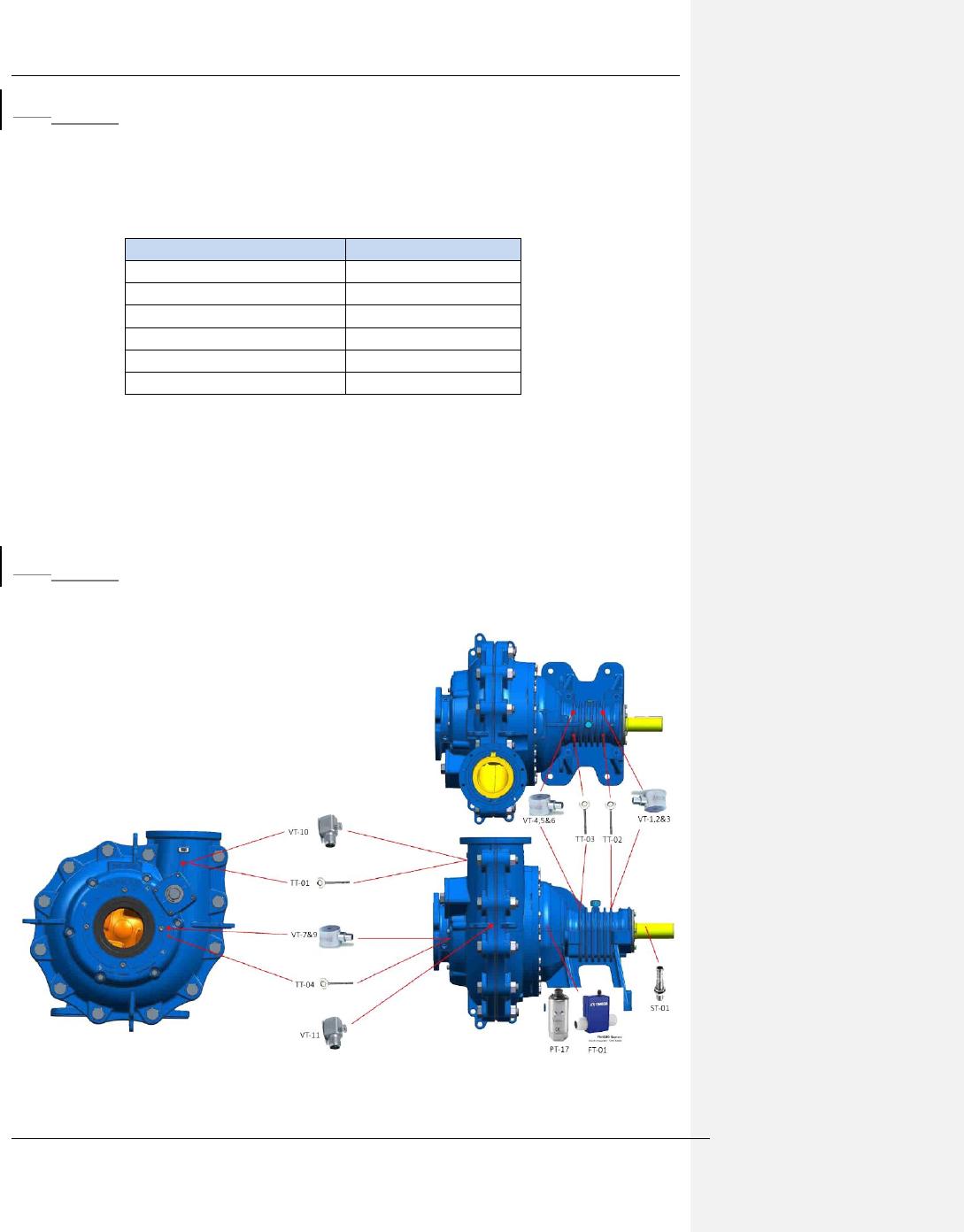
14.313.3 Sensor Install Locations
The following diagram shows the locations that sensors can be placed on a liquid pump.
Figure 13-1 Sensor Install Locations
The Weir Group PLC Weir Industrial Gateway setup guide rev 0.5
Copyright © Weir Minerals Australia Ltd 2017. Commercial in Confidence. All rights reserved. Page 34 of 46
14.413.4 Installation
Vibration and Temperature sensor mounting options:
There are two options available for mounting vibration and temperature sensors to the pump.
Choose the option that best suits your needs:
A. Directly to the pump via a drilled and tapped hole – typically used for bearing
assembly locations and ductile iron parts, intended to be created at time of
manufacture for all products where possible
B. Via an adhesively bonded mounting pad (fig 5.6 below). To be used when it is not
possible to drill and tap.
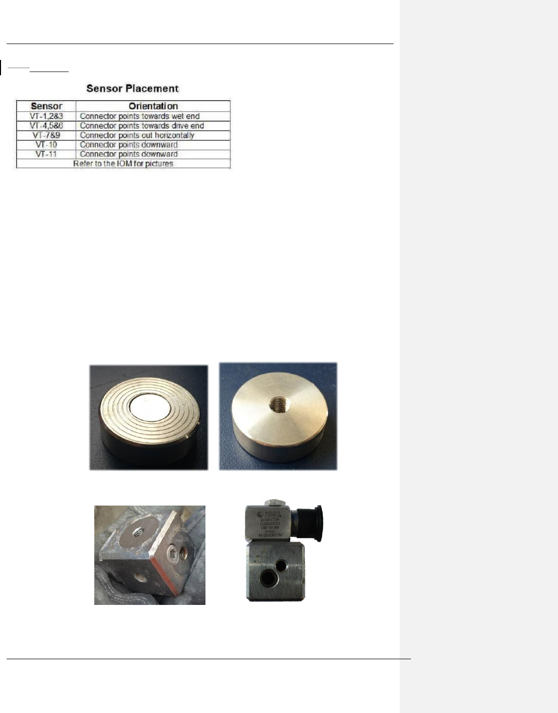
It is also possible to change the orientation of a single axis sensor by placing a placing a tri-
block mounting accessory in between the pump and the sensor. This is exclusively used for
single axis sensor VT-10 as described in section x.x below.
Figure 13-2 Slurry pump installation - mounting puck
Figure 13-3 Triblock mounting accessory
The Weir Group PLC Weir Industrial Gateway setup guide rev 0.5
Copyright © Weir Minerals Australia Ltd 2017. Commercial in Confidence. All rights reserved. Page 35 of 46
14.4.113.4.1 Mounting point Preparation
The first step in the installation is to determine what type of sensor mounting method is to be
used for each sensor. There are 7 locations that need to be drilled and tapped, or have a
mounting puck affixed. These locations are summarised in the quick start guide. As
mentioned before, cast iron parts can be drilled and tapped; white iron parts require a
mounting puck.
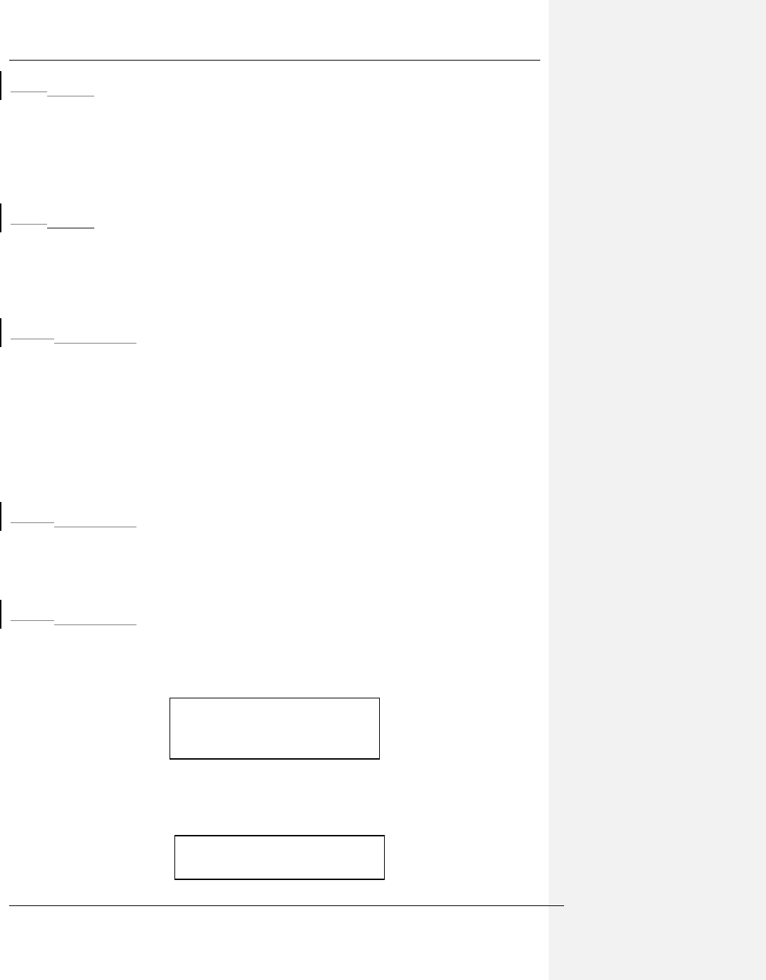
14.4.213.4.2 Adhesively bonded mounting puck
This approach is used where it is not viable to create a drilled and tapped hole. The mounting
pads provided a threaded hole to mount the sensor and a small magnet that assists in
keeping the pad in place whilst the adhesive cures.You must wait a minimum of 24 hours for
the adhesive to cure before attaching the sensor to the mounting puck.
14.4.2.113.4.2.1 Equipment and materials required
• Minimum PPE : eye protection, gloves, hard hat, long sleeves and trousers
• Wire brush
• Clean cloth
• Adhesive : Loctite Hysol 9461
• Abrasive paper eg 120grit
o A suitable portable drill tool can be used if approved by site
• Cleaning solvent eg isopropyl alcohol
• Plastic card or similar for mixing 2 part epoxy components
14.4.2.213.4.2.2 Hazards
- Epoxy represents a minor hazard needs to be handled with recommended PPE and
following manufacturer’s instructions
- Solvents can be skin irritants. Wear protective gloves in addition to standard PPE
14.4.2.313.4.2.3 Process
1. Clean area to be bonded using scraper and wire brush such that no paint, loose
material or large particles of debris remain. All paint, oils and solvents must be
removed for a good bond.
2. Wipe are down with degreasing/cleaning spirit to remove all traces of oils, grease,
dirt, water etc
3. Wipe mounting puck back surface and edges with cleaning sprit impregnated cloth
Insert picture of cleaned surface
ready for bonding. Note area to
be cleaned is ~= 30 mm and flat
Insert picture of puck back
surface, cloth and isopropyl
The Weir Group PLC Weir Industrial Gateway setup guide rev 0.5
Copyright © Weir Minerals Australia Ltd 2017. Commercial in Confidence. All rights reserved. Page 36 of 46
4. Allow both surfaces to dry such that no cleaning spirit/fluid/residue remains
5. Dispense epoxy onto mixing card and mix thoroughly
6. Apply enough epoxy to mounting puck such that the entire back surface will be
covered to at least 1mm thick
7. Place puck onto casing allowing magnet to hold in position during cure
Figure 13-4 Slurry pump - Mounting pump adhesively bonded to pump
8. Allow 24 hour cure time before installing sensors. Denso tape can be used to help
secure vertically mounted pucks if needed.
14.4.313.4.3 Drilled and tapped mount
This method is most often utilised for bearing assemblies but can also be used on suction
covers and casings made of cast iron. In this case, an official drawing will be provided by the
DCO indicating approved locations and depths of the tapped holes.
Show pictures of unmixed and
mixed epoxy, make note to even
amounts of A and B
Show picture of puck covered
with correct amount of epoxy
Insert picture of sensor held in
place with Denso tape
The Weir Group PLC Weir Industrial Gateway setup guide rev 0.5
Copyright © Weir Minerals Australia Ltd 2017. Commercial in Confidence. All rights reserved. Page 37 of 46
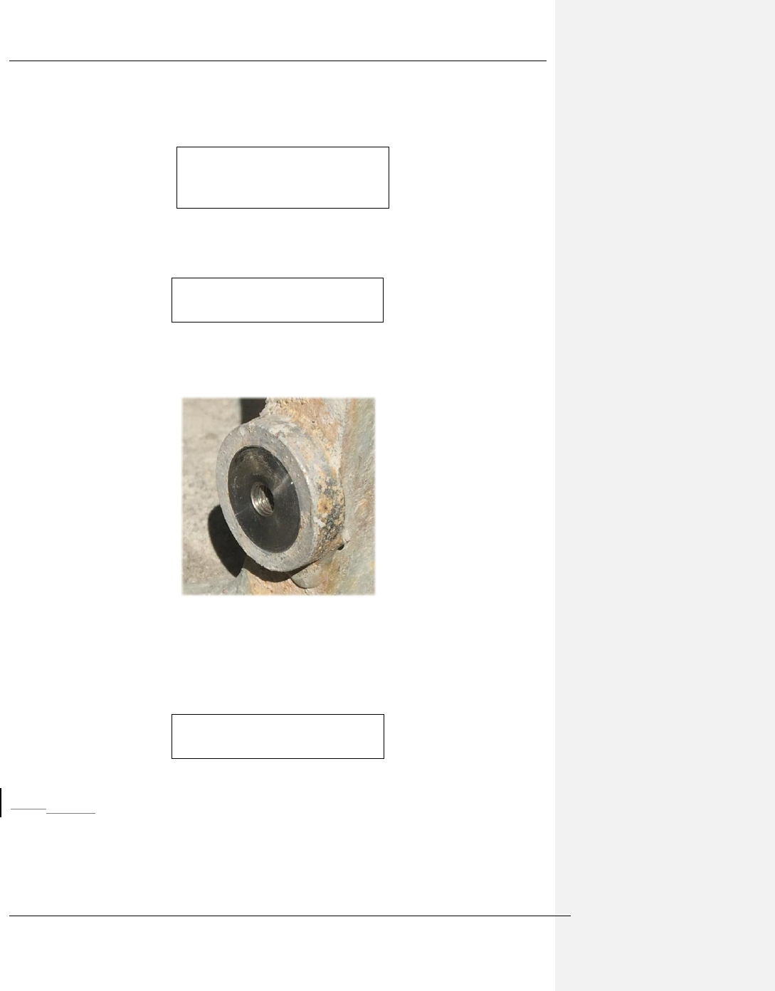
14.4.3.113.4.3.1 Equipment and Materials required
• Minimum recommended PPE: eye protection, hard hat, long sleeves and trousers –
do not wear gloves when using rotating
equipment.
• Drill, tap and facing kit HS-AA031 Series is
available from Hansford Sensors. The
product range includes all the necessary tools
needed to accurately mount a vibration sensor
onto the rotating machine. The packaged kit
includes; tapping drill, taps, tap wrench and a
spot facing tool. There are three versions of
the kit available to allow for different mounting
threads; ¼, M6 and M8. See
http://www.hansfordsensors.com/wp-content/uploads/datasheets/TS161U.pdf for
more information.
• Tapping compound/cutting fluid
• Battery drill
14.4.3.213.4.3.2 Hazards
- Swarth associated with drilling can be sharp. Do not brush away with your hands.
- Ensure that any electrical equipment is in good condition and meets site requirements
- Do not wear gloves whilst using rotating machinery
14.4.3.313.4.3.3 Process
1. Clean area to be tapped using scraper and wire brush such that no paint, loose
material or large particles of debris remain
2. Measure and mark locations as per the DCO drawing
3. Drill hole(s) and face mounting location with combined drill and facing tool
4. Tap hole to ¼” UNF using the hand tap. Ensure thread extends to a depth of
10mm
The Weir Group PLC Weir Industrial Gateway setup guide rev 0.5
Copyright © Weir Minerals Australia Ltd 2017. Commercial in Confidence. All rights reserved. Page 38 of 46
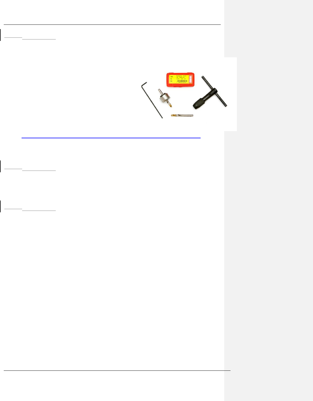
14.513.5 Accelerometer attachment
14.5.113.5.1 Equipment and materials required
• PPE: gloves, eye protection, hard hat, long sleeves and trousers
• Spanner/wrench – 7/16” (ring or open ended)
• 3/16” Allen key
• 2x uni-axial accelerometers (part # 602D02)
• 3x Tri-axial accelerometers (part # 604B32)
• 1x tri-axial mounting block
14.5.213.5.2 Installation
1. Ensure mounting puck or tapped hole and surrounding surface is clean and free of
debris/particles
2. Connect each sensor cable to the allocated sensor making sure to use the correct
cable and observe keyways (cables have stamped metal labels)
3. Wrap connector interface including nut and exposed thread with Nitto No.15 tape, as
shown in Figure 13-5Figure 9-5.
Figure 13-5 Uni-axial accelerometer with connector and protective tape applied
4. Screw Accelerometer thru-bolt or cap screw into mounting puck or prepared threaded
5. Tighten to approximately 3 Nm using 3/16” allen key (tri-axial sensors) or 7/16”
spanner/wrench (uni-axial sensors)
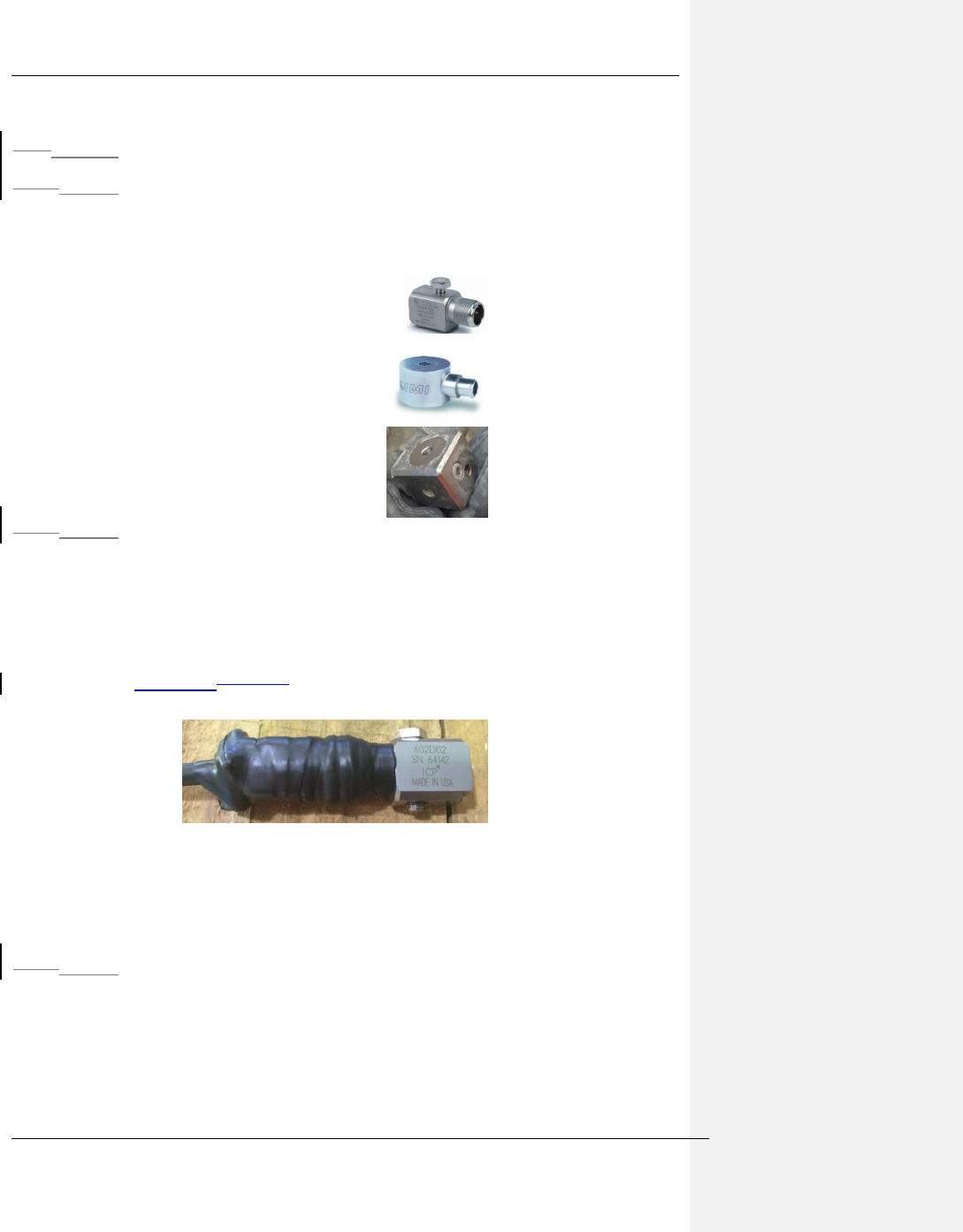
14.5.313.5.3 VT-11
A tri-axial mounting block is used to mount the cutwater vibration sensor at right angles to the
surface. This mounting block is fitted in between the pump and the sensor in order to change
the orientation of the sensor.
1. Mount the tri-block to the pump as shown, using a 3/16” allen key.
The Weir Group PLC Weir Industrial Gateway setup guide rev 0.5
Copyright © Weir Minerals Australia Ltd 2017. Commercial in Confidence. All rights reserved. Page 39 of 46
Figure 13-6 Tri-Block
14.5.413.5.4 Removal
1. Release cap screw or retaining bolt and remove sensor from mounting point
2. If required to disconnect sensor from cable :
a. Unwrap protective tape
b. Remove connector
c. Install plastic bung/cap on both sensor and cable connectors
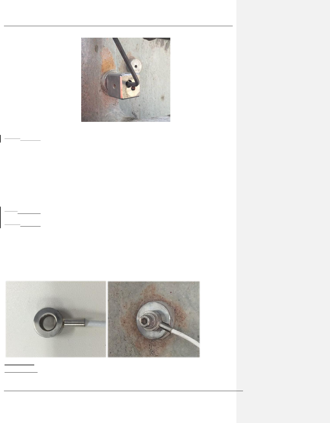
14.613.6 Temperature RTD’s
14.6.113.6.1 Equipment and materials required
• Minimum recommended PPE : gloves, eye protection, hard hat, long sleeves and
trousers
• Allen key. 3/16”
• Small Philips screwdriver
• ¼” UNF x 1” long cap screw and washer x qty 4
• RTD leads (part # SD014-3M) x qty 4
Figure (left): RTD ring at end of 3m lead
Figure (right): RTD fastened to magnetic mount
Figure 13-7 RTD

The Weir Group PLC Weir Industrial Gateway setup guide rev 0.5
Copyright © Weir Minerals Australia Ltd 2017. Commercial in Confidence. All rights reserved. Page 40 of 46
14.6.213.6.2 Hazards
- No task specific hazards of note
14.6.313.6.3 Installation
1. Ensure mounting puck/location surface is clean and free of debris/particles
2. Fasten the RTD’s to the mount locations specified in section x.x
3. Screw cap-screw into mounting puck
4. Tighten to approximately 3 Nm using 3/16” allen key
14.6.413.6.4 Removal
1. Release cap screw and remove sensor from mounting point
2. Install screw back into mounting hole to prevent slurry/crud from entering thread
14.713.7 Gland Water Flow Meter and Pressure Transducer
14.7.113.7.1 Equipment and materials required
• Minimum recommended PPE : gloves, eye protection, hard hat, long sleeves and
trousers
• Spanner/wrench to suit pipe fittings
• 1 ¼” open end spanner/wrench (for Pressure transducer)
• 1x Flow Meter (part # xxxxxxx)
• 1x Pressure Tranducer (part # xxxxxxxx)
• Protective tape – Nitto Self-fusing Butyl Rubber Tape – No.15
• Plumbers thread tape
14.7.213.7.2 Possible Hazards
- Water within the gland supply system may be at elevated pressure, enough to cause
eye damage if accidentally directed into the eye
- Gland water supply is not likely potable water hence should not be ingested or
allowed to come into contact with the face
14.7.313.7.3 Installation
1. Ensure the gland supply is depressurised and the pump is not running
2. The pressure transducer and flow meter must be installed in series with the gland
water supply
3. Fittings to install the pressure and flow sensors are site specific and not supplied.
These should have been identified in the site survey and purchased ahead of
time. This will include a suitable T fitting for the pressure sensor.
4. The suggested installation location is after an isolation valve (shown in image
below).
5. Connect pressure and flow sensors to main cable harness.
6. Wrap connector interfaces with protective tape (Nitto No.15).
The Weir Group PLC Weir Industrial Gateway setup guide rev 0.5
Copyright © Weir Minerals Australia Ltd 2017. Commercial in Confidence. All rights reserved. Page 41 of 46
Replace image with new hardware
Figure 13-8 Gland water sensor installation
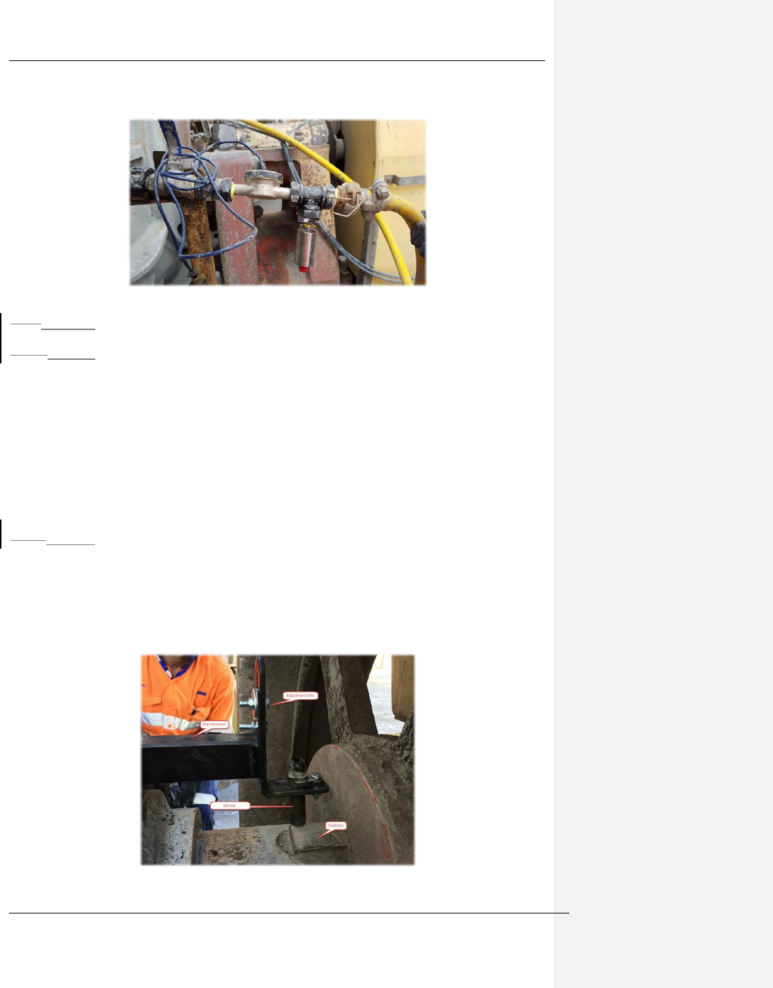
14.813.8 Speed – Proximity sensor
14.8.113.8.1 Equipment and materials required
• Spanner/wrench – as required for particular mounting bracket and bearing assembly
• Fasteners
• 1x Speed Sensor (Part # 872C-N8NP12-04)
• Mounting bracket (dwg xxxxx)
• Target bracket (dwg xxxxxx
• Protective tape – Nitto Self-fusing Butyl Rubber Tape – No.15
• Gap measurement tool
• Speed sensor integrity check tool
14.8.213.8.2 Hazards
- The Pump Shaft speed sensor is mounted off the motor end of the bearing assembly.
- To install the speed sensor the motor must be turned off and tagged out for safety
- There may also be pinch or crush hazards when/if the shaft is rotated during the
alignment process
Figure 13-9 Speed sensor mount example (new picture required)

The Weir Group PLC Weir Industrial Gateway setup guide rev 0.5
Copyright © Weir Minerals Australia Ltd 2017. Commercial in Confidence. All rights reserved. Page 42 of 46
14.8.313.8.3 Installation
1. Clean shaft and bearing housing mount points of all slurry/debris
2. Loosely mount the target on the shaft.
3. Mount the sensor bracket onto the bearing assembly
4. Loosely secure the speed sensor into the sensor bracket
5. Align the speed sensor and the shaft target bracket so that the speed sensor is
directly above the target
6. Tighten both the target collar to the shaft and the lateral adjustment of the speed
sensor
7. Adjust the vertical motion of the speed sensor so that the gap is no more than 2mm
and tighten
8. Rotate the shaft to the edge of target and measure the gap. Ensure it is no more than
1mm and that it is not touching the corner.
9. Connect the speed sensor to the test box. Rock the shaft back and forth, ensuring
that the indicator LED on the test box illuminates each time the target passes under
the sensor
10. Remove the test box from the sensor and connect the regular cable
11. Wrap connector interface with protective tape (Nitto No.15)
1514 Cleaning and Maintenance
The enclosure of the system is able to withstand slurry. This slurry should be removed
periodically with the use of water and a stiff brush. The use of pressurized water can also used to
clean the system.
There are no user serviceable parts inside the system. Technical support issues with this system
are available at:
Attn: Richard Smith
Sanmina
Unit 3, Cherrywood, Chineham, Basingstoke, UK RG24 8WF
United Kingdom
Telephone: +44 1256 637371
1615 Regulatory Compliance
The Weir Industrial Gateway system comprising of the PSM, MPM, and RSP are designed
and tested to comply with/meet the following standards:
16.115.1 Electromagnetic Compatability
o FCC Part 15 Subject B class A
o CISPR 22 Class A, EN55022 Level B
o ICES-003 Class A
o AS/NZS CISPR 32:2013

The Weir Group PLC Weir Industrial Gateway setup guide rev 0.5
Copyright © Weir Minerals Australia Ltd 2017. Commercial in Confidence. All rights reserved. Page 43 of 46
Note: This equipment has been tested and found to comply with the limits for a Class A
digital device, pursuant to part 15 of the FCC Rules. Operation is subject to the following two
conditions: (1) This device may not cause harmful interference, and (2) this device must
accept any interference received, including interference that may cause undesired operation.
These limits are designed to provide reasonable protection against harmful interference
when the equipment is operated in a commercial environment. This equipment generates,
uses, and can radiate radio frequency energy and, if not installed and used in accordance
with the instruction manual, may cause harmful interference to radio communications.
Operation of this equipment in a residential area is likely to cause harmful interference in
which case the user will be required to correct the interference at his own expense.
This Class A digital apparatus complies with Canadian ICES-003.
Cet appareil numérique de la classe A est conforme à la norme NMB-003 du Canada.
16.215.2 Hazardous Location Compliance
The MPM, RSP, and power supply are certified to meet the following hazardous location
standards and gas groups
o Class I Division 2, Groups B,C,D T3
o Class I Zone 2, AEx nA IIB+H2 T3
o Ex II 3GD EEx nA IIB+H2 T3 Dc
Canada / US Hazardous Location Compliance
o ANSI/ISA 12.12.01: Nonincendive Electrical Equipment for Use in Class I and
II, Division 2 and Class III, Divisions 1 and 2 Hazardous (Classified) Locations
o CAN/CSA C22.2 No. 213: Non-Incendive Electrical Equipment for Use in
Class I, Division 2 Hazardous Locations
European / International Hazardous Location Compliance
o EN 60079-0, IEC 60079-1 : Electrical Apparatus for Explosive Gas
Atmospheres Part 0: General Requirements
o EN 60079-15, IEC 60079-15 : Electrical Apparatus for Explosive Gas
Atmospheres Part 15: Electrical Apparatus with Type of Protection "n"
MPM IECEx certificate no: IECEx EMT 17.0018X
MPM ATEX certificate no: EMT17ATEX0043X
RSP certificate no: EMT17ATEX0044X
The sensors chosen to be used by this system will need to be certified to the hazardous
location compliance directives applicable to the country where the installation takes place.
External devices like a QPro radio and external model are not covered in a hazardous
location and will need to be placed outside of the hazardous location area. All connections
within a hazardous location area will need to have the locking connectors installed in order to
prevent accidental disconnection of these connectors.

The Weir Group PLC Weir Industrial Gateway setup guide rev 0.5
Copyright © Weir Minerals Australia Ltd 2017. Commercial in Confidence. All rights reserved. Page 44 of 46
16.315.3 Safety
o UL 61010-1, CSA C22.2 No. 61010-1, EN 61010-1, IEC 61010-1 : Safety
Requirements for Electrical Equipment For Measurement, Control, and
Laboratory Use; Part 1
16.415.4 Radio Approvals
o FCC Part 15 Subpart B, C, E
o FCC Part 22 Subpart H
o FCC Part 24 Subpart E
o FCC Part 27 Subpart E
o ETSI EN 301 489-1
o ETSI EN 301 489-17
o ETSI EN 301 489-52
o ETSI EN 300 328
o ETSI EN 301 893
o ETSI EN 301 511
Radio FCC ID: 2ANXR-STXMPM
<Radio Power levels also needed for hazardous location compliance>
This section includes user requirements for operating this product in accordance with
National laws for usage of radio spectrum and operation of radio devices. Failure of the end-
user to comply with the applicable requirements may result in unlawful operation and
adverse action against the end-user by the applicable National regulatory authority.
Note: This product’s firmware limits operation to only the channels allowed in a particular
Region or Country. Therefore, all options described in this user's guide may not be available
in your version of the product.
WWAN Antenna
This device has been designed to operate with the antennas listed below, and having a
maximum gain of 3 dB. Antennas not included in this list or having a gain greater than 3 dB
are strictly prohibited for use with this device. The required antenna impedance is 50 ohms.
o Mobile Mark OD3-700/2700-BLK antenna, 694-960 MHz: 2 dBi; 1700-2700
MHz: 3 dBi

The Weir Group PLC Weir Industrial Gateway setup guide rev 0.5
Copyright © Weir Minerals Australia Ltd 2017. Commercial in Confidence. All rights reserved. Page 45 of 46
WLAN Antenna
This device has been designed to operate with the antennas listed below, and having a
maximum gain of 12 dB. Antennas not included in this list or having a gain greater than 12
dB are strictly prohibited for use with this device. The required antenna impedance is 50
ohms.
o Mobile Mark OD6-2400-BLK antenna, 6dBi
o Mobile Mark SCR12-2400-WHT high gain antenna, 12dBi
16.4.115.4.1 FCC Requirements for Operation in the United States:
This product does not contain any user serviceable components and is to be used with
approved antennas only. Any product changes or modifications will invalidate all applicable
regulatory certifications and approvals.
16.4.215.4.2 FCC RF Radiation Exposure:
The radio has been evaluated under FCC Bulletin OET 65C (01-01) and found to be
compliant to the requirements as set forth in CFR 47 Sections, 2.1093, and 15.247 (b) (4)
addressing RF Exposure from radio frequency devices. This model meets the applicable
government requirements for exposure to radio frequency waves.
This equipment complies with the FCC RF radiation exposure limits set forth for an
uncontrolled environment. The antennas used for this transmitter must be installed to
provide a separation distance of at least 20 centimetres from all persons and must not be co-
located or operating in conjunction with any other antenna or transmitter.
To comply with FCC RF exposure compliance requirements, a separation distance of at least
33.9 centimetres must be maintained between the user and antenna when the product is
used with the SCR12-2400-WHT high gain antenna.
To reduce potential radio interference to other users, the antenna type and its gain should be
so chosen that the equivalent isotropically radiated power (e.i.r.p.) is not more than that
permitted for successful communication.
16.4.315.4.3 Industry Canada Requirements for Radio Operation in Canada:
This device complies with Industry Canada licence-exempt RSS standard(s). Operation is
subject to the following two conditions: (1) this device may not cause interference, and (2)
this device must accept any interference, including interference that may cause undesired
operation of the device.
Le présent appareil est conforme aux CNR d'Industrie Canada applicables aux appareils
radio exempts de licence. L'exploitation est autorisée aux deux conditions suivantes : (1)
l'appareil ne doit pas produire de brouillage, et (2) l'utilisateur de l'appareil doit accepter tout
brouillage radioélectrique subi, même si le brouillage est susceptible d'en compromettre le
fonctionnement.

The Weir Group PLC Weir Industrial Gateway setup guide rev 0.5
Copyright © Weir Minerals Australia Ltd 2017. Commercial in Confidence. All rights reserved. Page 46 of 46
Under Industry Canada regulations, this radio transmitter may only operate using an antenna
of a type and maximum (or lesser) gain approved for the transmitter by Industry Canada. To
reduce potential radio interference to other users, the antenna type and its gain should be so
chosen that the equivalent isotropically radiated power (e.i.r.p.) is not more than that
necessary for successful communication.
Conformément à la réglementation d'Industrie Canada, le présent émetteur radio peut
fonctionner avec une antenne d'un type et d'un gain maximal (ou inférieur) approuvé pour
l'émetteur par Industrie Canada. Dans le but de réduire les risques de brouillage
radioélectrique à l'intention des autres utilisateurs, il faut choisir le type d'antenne et son gain
de sorte que la puissance isotrope rayonnée équivalente (p.i.r.e.) ne dépasse pas l'intensité
nécessaire à l'établissement d'une communication satisfaisante.
This radio transmitter IC:23347-STX000004 has been approved by Industry Canada to
operate with the antenna types listed below with the maximum permissible gain and required
antenna impedance for each antenna type indicated. Antenna types not included in this list,
having a gain greater than the maximum gain indicated for that type, are strictly prohibited for
use with this device.
Le présent émetteur radio IC:23347-STX000004 a été approuvé par Industrie Canada pour
fonctionner avec les types d'antenne énumérés ci-dessous et ayant un gain admissible
maximal et l'impédance requise pour chaque type d'antenne. Les types d'antenne non inclus
dans cette liste, ou dont le gain est supérieur au gain maximal indiqué, sont strictement
interdits pour l'exploitation de l'émetteur.