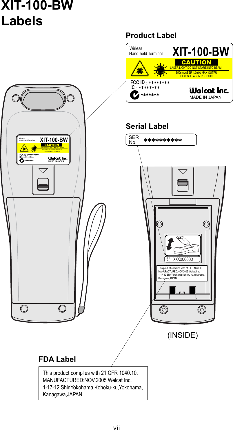
Welcat XIT100BW Barcode Reader with 802.11b&Bluetooth; Transmitters User Manual 1 of 2
Welcat, Inc. Barcode Reader with 802.11b&Bluetooth; Transmitters 1 of 2
Welcat >
Contents
- 1. User Manual 1 of 2
- 2. User Manual 2 of 2
User Manual 1 of 2


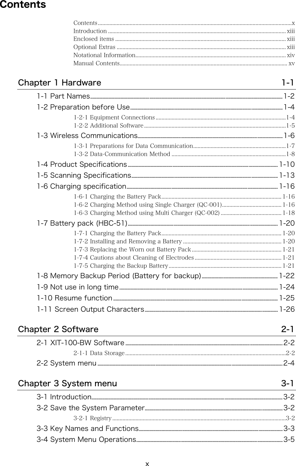
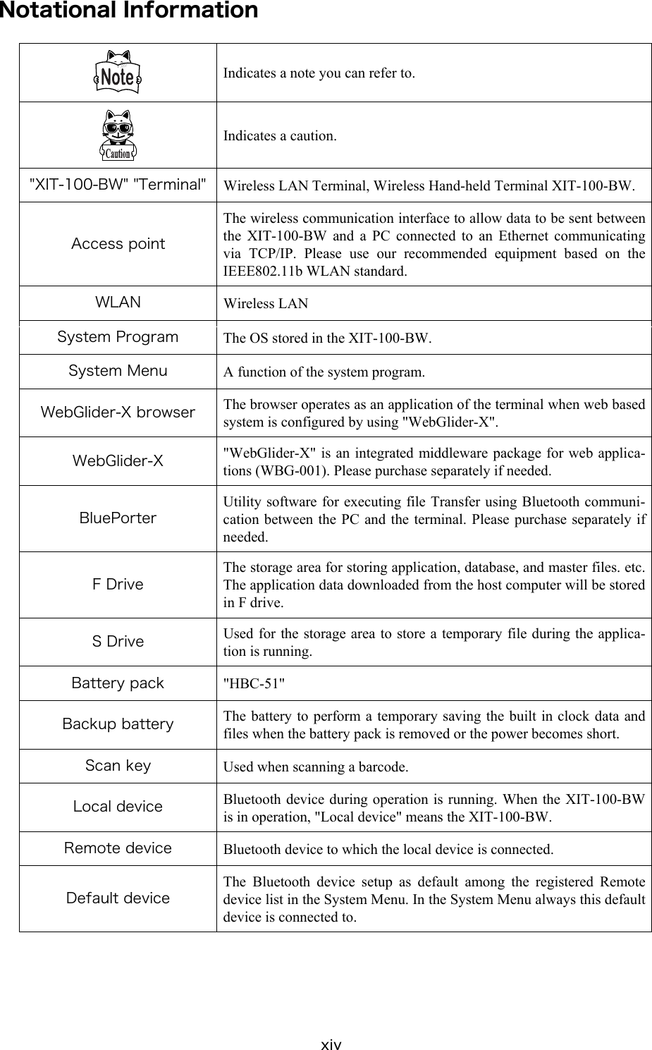


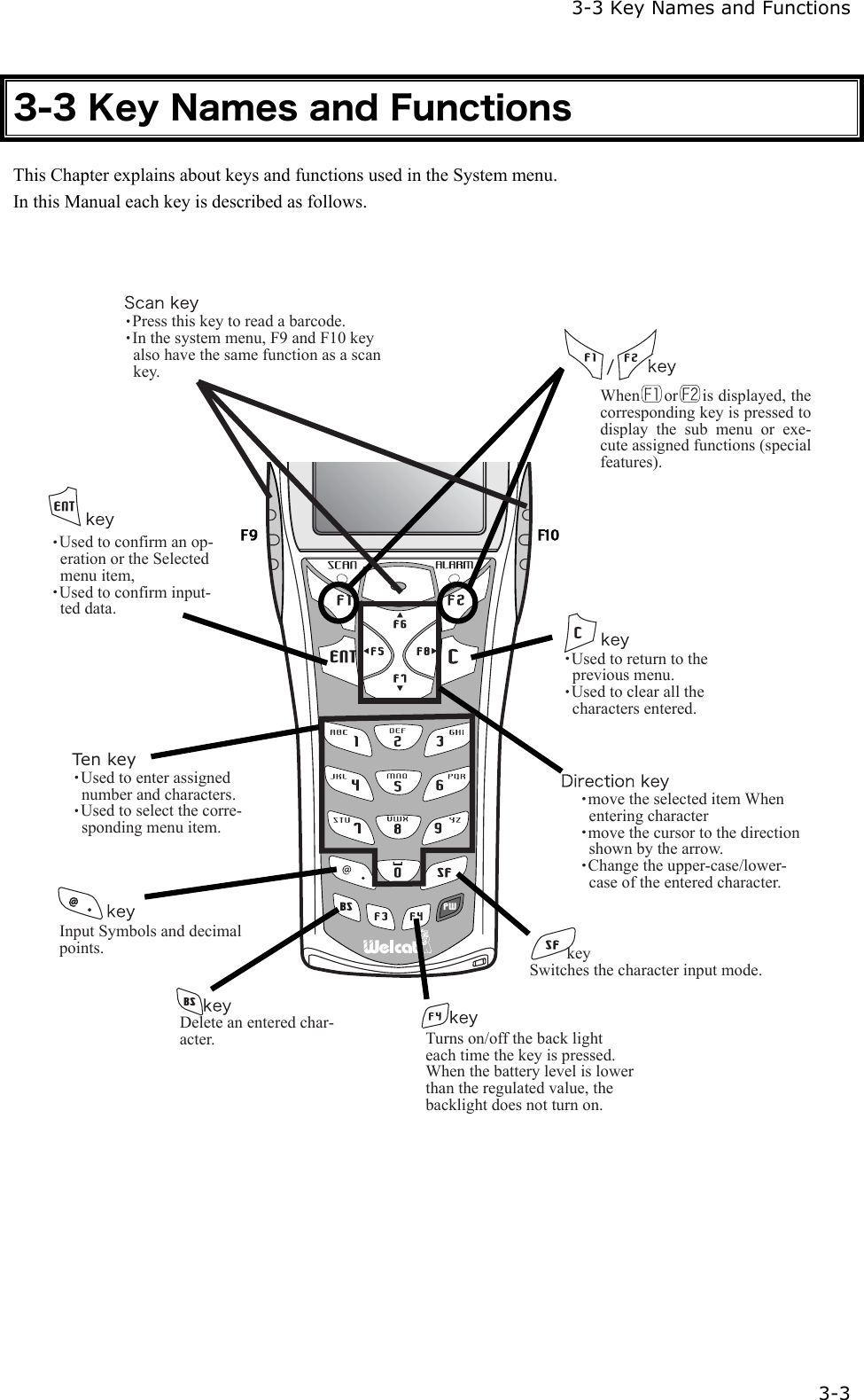
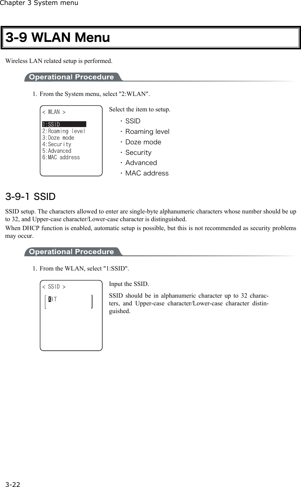
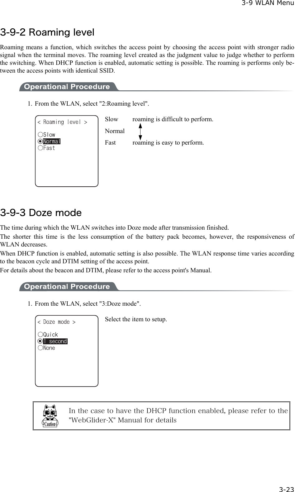
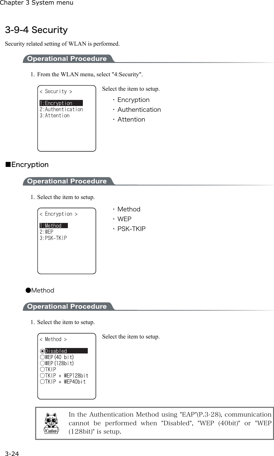
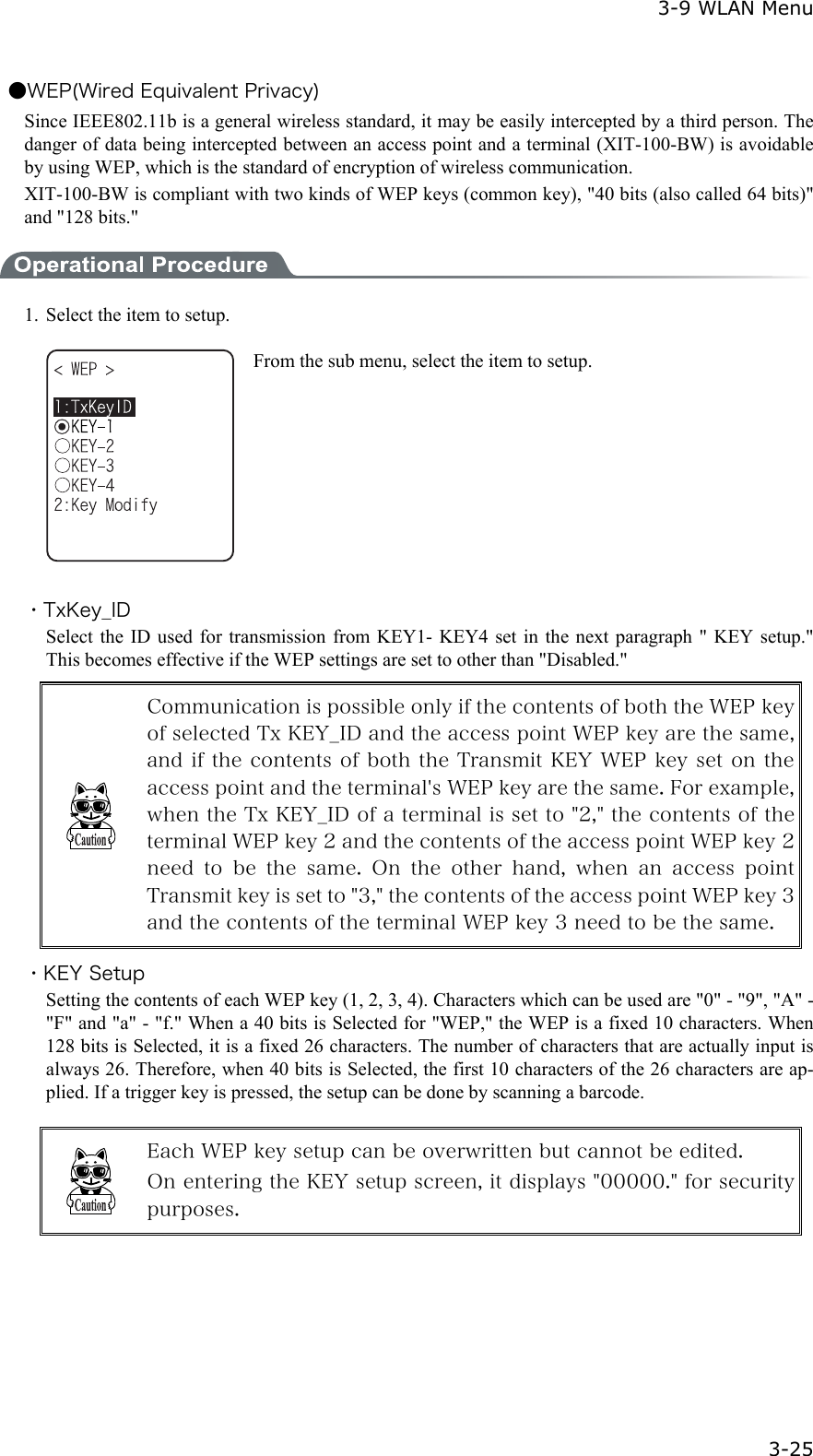
![3-4 System Menu Operations 3-5 3-4 System Menu Operations Here explains the Standard Operation Method of the System menu. ■Select the target item from the menu ●Selecting a Menu Item Selected item becomes highlighted (colors reversed= selected). Move the cursor either by pressing to key, which corresponds to the item, or, by using the di-rection ( to ) key. ●confirm the selected item Press the key, and, confirm the selected item. The behavior after confirmation differs according to the item. ・ Execute the corresponding function ・ Show the decision [Yes] or [No] (check box) ・ Next Menu is displayed. ・ Sub menu is displayed. ●Cancel Selecting Press the key, to return to the previous operation. ●Screen display When the items in the Menu are not housed in a screen, the scroll bar for vertical direction is dis-played on the right of the screen. In addition, when the item name exceeds 1 line, the tail of the item name is displayed being converted in "→ " ■Input Barcode data ●Barcode Scanning Press the scan key and irradiates the laser to scan a barcode. The irradiation time of the laser and scanning behavior are set up with trigger mode. In addition, Bar-code test menu is not subject to trigger mode. ●Barcode scanning condition The Barcode that can be scanned in the data input mode is as follows. NW-7, CODE39, JAN13/8, UPC-A/E, Industrial 2of5, ITF, CODE93, CODE128, RSS-14, RSS Limited](https://usermanual.wiki/Welcat/XIT100BW.User-Manual-1-of-2/User-Guide-613365-Page-55.png)
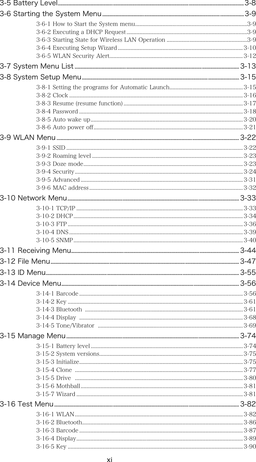
![3-4 System Menu Operations 3-7 ■Other operations ●Returning to the previous menu. Press the key. ●Check box operation By applying or removing checks in the square box, making the item selected/not selected. Each time the key is pressed, the status of Select /Not Select switches. Each time the key is pressed ,[Yes]/[No] switches. The check box is also applied when selecting many items at the same time. ●Radio buttun operation The item the inside of the small circle is dotted shows that it is currently enabled. Radio button is used to select one item from many items. ●Message box operation When two buttons are displayed in the lower part of the box; [Yes]/[No] etc., press or, key, or select the button by using the direction ( to ) key (Highlighted), and then press the key to confirm. Press the key to select the right button. In such a case with one button like "OK", press the key or key. ●Level meter operation. Setup value adjustment by stages. Move the slider Up and Down by / key. And then, press the key to confirm the level value. Press the key to cancel setup. ●Turning ON/ OFF the backlight. Each time by pressing the key, the backlight turns ON/ OFF. However in case the battery level is less than the regulated value, the backlight does not turn ON. ●Accessing to the Sub menu or function. When or is displayed in the lower part of the screen, press the corresponding key to display the Sub menu or execute the function. ●Modifying the indicator when operating The indicator (buzzer/audio/vibrator/LED) that works when operating allows itself to be modified to user's original setup. With regard to the modification Method, please refer to"■Indicator func-tion"(P.3-69). By modifying this setup users' are allowed to create their original indicator easily. In addition, there are some operations that the indicator is not applied.](https://usermanual.wiki/Welcat/XIT100BW.User-Manual-1-of-2/User-Guide-613365-Page-57.png)
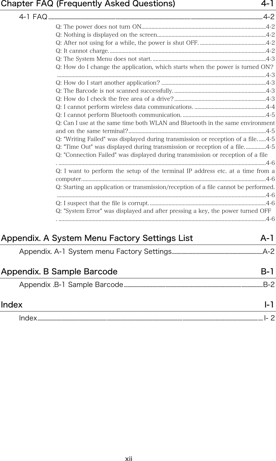
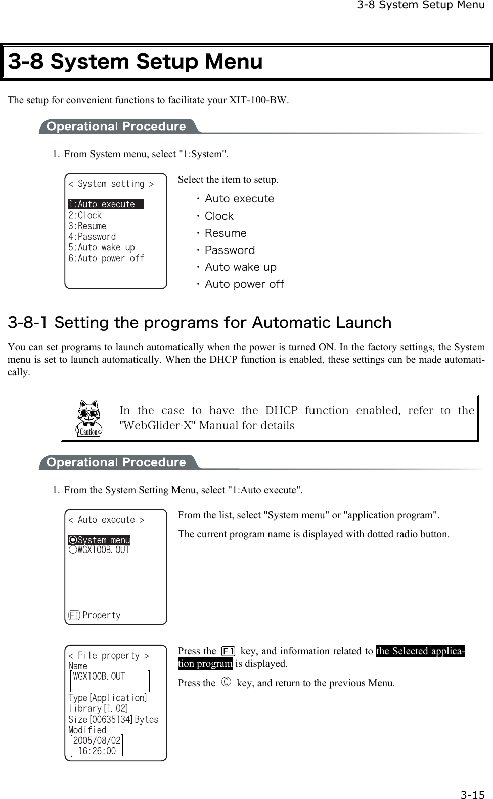
![3-6 Starting the System Menu 3-9 3-6 Starting the System Menu 3-6-1 How to Start the System menu 1. Once the XIT-100-BW has been correctly installed with a battery pack and if the current state is OFF, press the key for approximately 1 second. The power will turn ON and the System menu will be started. 2. The System menu is displayed immediately after the opening screen. If an application is set for " Auto execute" (P.3-15), hold down the scan key (excluding F9 and F10), and then press the key to start the System menu. 3-6-2 Executing a DHCP Request If the "■Startup type"(P3-35)is setup at[application boot], [System menu boot], the DHCP request will be executed every time of booting. If the system is in the state where wireless communications with an access point is possible and if the DHCP server and FTP server of the "WebGlider-X " Net-work Manager have been started, the various environmental setting values and specified files will be downloaded to the XIT-100-BW and automatic setup will be perform via the TCP/IP network. After the DHCP request has been executed, the applications set for "Auto exe-cute" if any, will start. (P.3-15) 3-6-3 Starting State for Wireless LAN Operation Immediately after starting, the XIT-100-BW's wireless LAN communication unit is set to a resumed state. If the wireless communications related menu is selected immediately after starting, the XIT-100-BW will be ready for communication within 0.5 to 1 second.](https://usermanual.wiki/Welcat/XIT100BW.User-Manual-1-of-2/User-Guide-613365-Page-59.png)
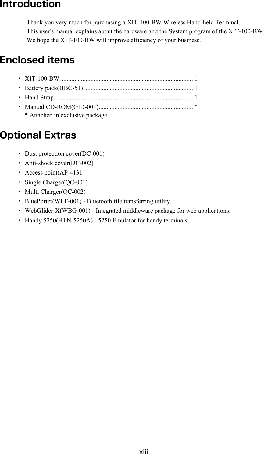
![Chapter 3 System menu 3-10 3-6-4 Executing Setup Wizard At the initial startup of the terminal, the setup wizard is executed to perform the minimum setup of the request for communication between the terminal and the server. Select either[Yes]or [No]. Select [Yes], then the wizard will be executed to perform the setup of WLAN and TCP/IP. Select [No], then the System menu will start up. When selecting [No] to skip the Setup Wizard, or, completing the setup to the last moment by executing Setup Wizard, the Setup Wizard will not startup from next time and after. Each item to be entered in the Setup Wizard can be set up each by each in the System menu. In addition, Setup Wizard can be arbitrarily executed from the System menu (P.3-81).](https://usermanual.wiki/Welcat/XIT100BW.User-Manual-1-of-2/User-Guide-613365-Page-60.png)
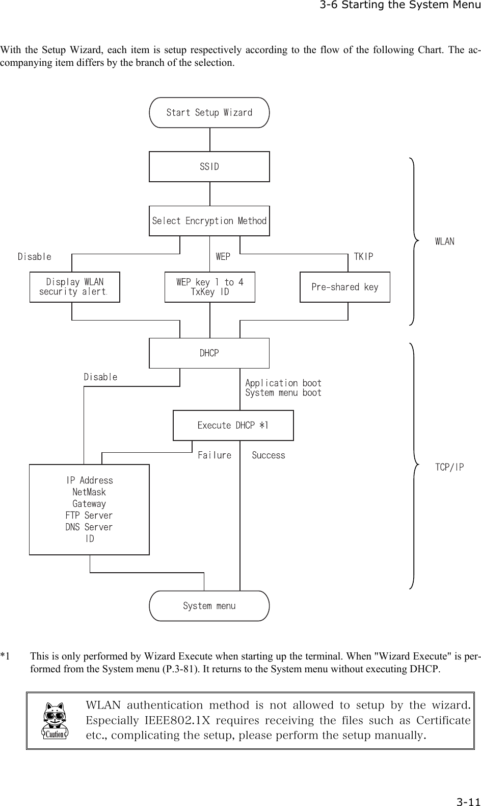
![Chapter 3 System menu 3-12 3-6-5 WLAN Security Alert When the WLAN Encryption Method is disabled, the dialog to alert the setup is displayed at the time of starting up. Select either from [Yes] or [No] Select [Yes], moves to "2:WLAN". Select [No], System menu is displayed. When the resume is enabled, this dialog is not displayed.](https://usermanual.wiki/Welcat/XIT100BW.User-Manual-1-of-2/User-Guide-613365-Page-62.png)
![3-8 System Setup Menu 3-17 1. Receiving the time data from the DHCP of "WebGlider-X" Network Manager. Press key or key to return to check the current time. When receiving is failed, the screen on the left is displayed. [Select RETRY], to receive the Time data from the server again. Select [CANCEL], or Press the key to cancel setup and return to Current time. 3-8-3 Resume (resume function) The XIT-100-BW supports a resume function. The resume function can be enabled through the System menu and if selected, the next time the key is pressed on the XIT-100-BW, the resume function will be used. Resume mode ON after the XIT-100-BW is powered OFF, the next time the key is pressed, it will resume operation where it was just before the power was turned OFF. For details of the resume function, please refer to the "1-10 Resume function"(P.1-25). ●Resume mode ON After the XIT100B is powered OFF, the next time the key is pressed, it will resume operation where it was just before the power was turned OFF. (Power ON, pressing the key while pressing the scan key to cancel resume mode) ●Resume Fail Resume setup will fail when the power OFF by removing the bat-tery and without pressing the key.](https://usermanual.wiki/Welcat/XIT100BW.User-Manual-1-of-2/User-Guide-613365-Page-67.png)
![3-8 System Setup Menu 3-19 ■Password setting 1. Input a new password. Password should be alphanumeric characters from 4 to 30, Up-per-case character/Lower-case character are distinguished. Input a new password, then, press the key. 2. Input the password again. After the password is entered, confirm by pressing the key. ■Clearing a Password 1. From the confirmation dialog, select[Yes]. The setup password is erased. Select [No], or press the key, and clear to stop.](https://usermanual.wiki/Welcat/XIT100BW.User-Manual-1-of-2/User-Guide-613365-Page-69.png)
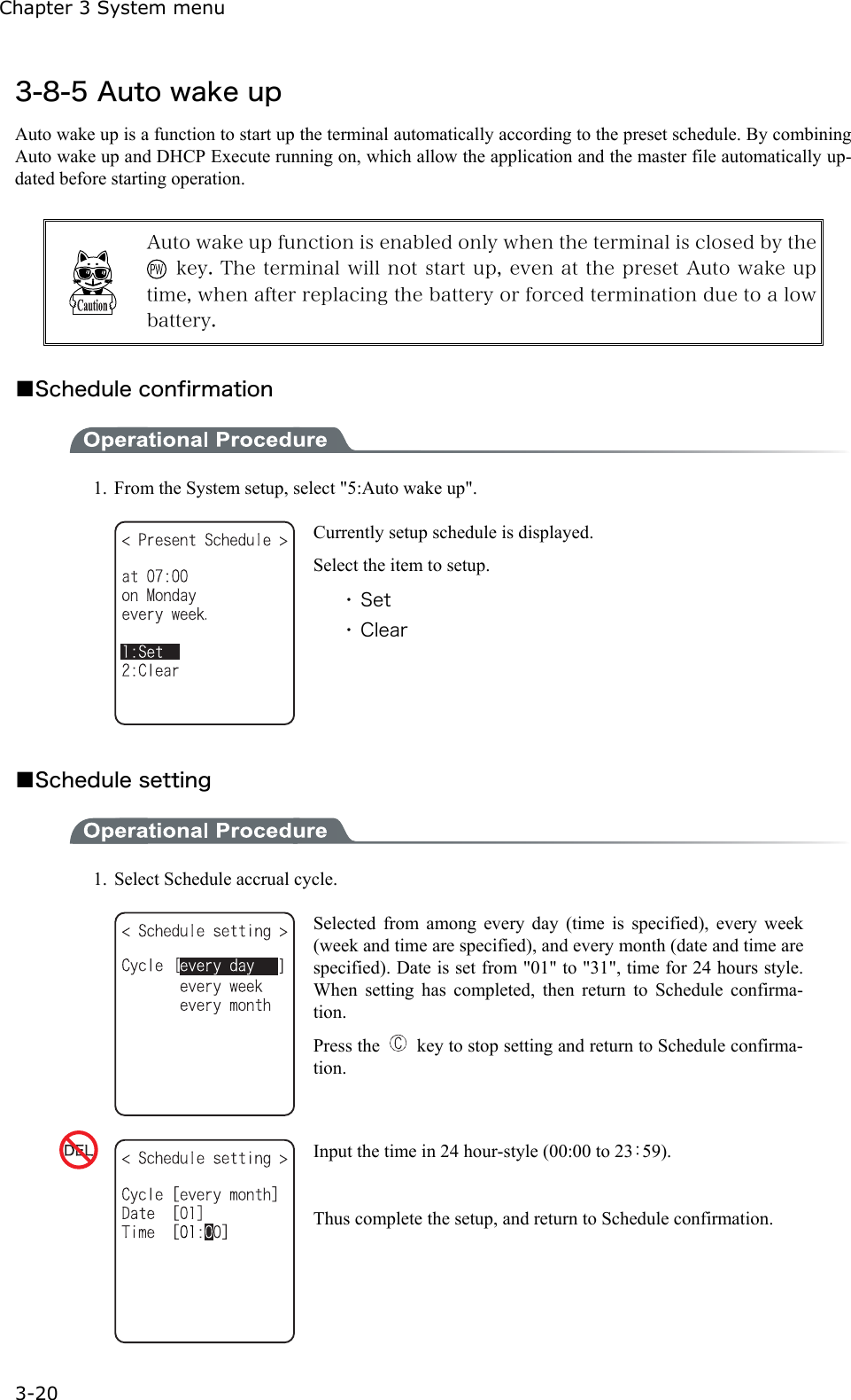
![3-8 System Setup Menu 3-21 ■Schedule Clearing 1. From the confirmation dialog, select[Yes]. The setup Schedule is erased. Select [No], or Press the key to stop clearing. 3-8-6 Auto power off Auto power off is a function to make the power OFF automatically when there is no operation performed for a certain period. 1. From the System setup, then select "6:Auto power off". Input the Auto power off time. The time allowed to setup is from 0060 seconds to 3600 seconds. In addition, when set to 0000 seconds, the Auto power off is disabled.Press the key, and, setup value related guidance is displayed.](https://usermanual.wiki/Welcat/XIT100BW.User-Manual-1-of-2/User-Guide-613365-Page-71.png)