Welch Allyn WA11A07 Welch Allyn 802.11a Wireless PC Card User Manual Micropaq Monitor Directions for Use
Welch Allyn, Inc. Welch Allyn 802.11a Wireless PC Card Micropaq Monitor Directions for Use
Contents
- 1. User Manual part 1 of 2
- 2. User Manual part 2 of 2
User Manual part 1 of 2
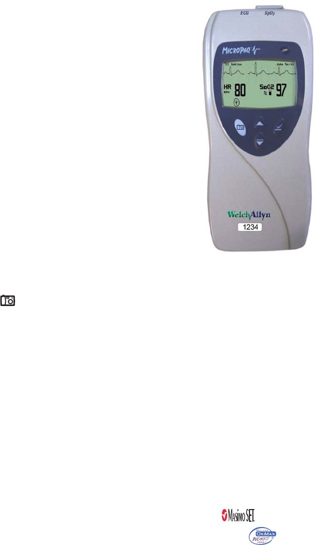
Micropaq
®
Monitor
Directions for Use
Model 406 and Model 408
Software version 1.7X

ii Welch Allyn Micropaq Monitor
Copyright 2007, Welch Allyn. All rights are reserved. No one is permitted to reproduce or duplicate, in any form, this manual
or any part thereof without permission from Welch Allyn.
Welch Allyn assumes no responsibility for injury or for any illegal or improper use of the product that may result from failure
to use this product in accordance with the instructions, cautions, warnings, or indications for use published in this manual.
Welch Allyn®, Acuity®, Micropaq®, FlexNet® and Flexible Monitoring® are registered trademarks of Welch Allyn, Inc.
Nellcor® is a registered trademark of Nellcor Puritan Bennett. Masimo® and SET® are registered trademarks of Masimo
Corporation.
Software in this product is Copyright 2007, Welch Allyn or its vendors. All rights are reserved. The software is protected by
United States of America copyright laws and international treaty provisions applicable worldwide. Under such laws, the
licensee is entitled to use the copy of the software incorporated within this instrument as intended in the operation of the
product in which it is embedded. The software may not be copied, decompiled, reverse-engineered, disassembled or
otherwise reduced to human-perceivable form. This is not a sale of the software or any copy of the software; all right, title
and ownership of the software remain with Welch Allyn or its vendors.
For information about any Welch Allyn product, please call Welch Allyn Technical Support:
This device complies with Part 15 of the FCC rules and with the rules of the Canadian ICES-003. Operation is subject to the
following two conditions: (1) This device may not cause harmful interference and (2) this device must accept any interference
received, including interference that may cause undesired operation.
Reorder Part Number 810-2691-XX
Manual Part Number 810-2702-00 Rev A, 10/2007
www.welchallyn.com
Printed in USA
USA 1 800 535 6663
+ 1 315 685 4560 Australia + 6129 638 3000
800 074 793
Canada 1 800 561 8797 China + 86 216 327 9631
European Call Center + 353 46 906 7790 France + 331 6009 3366
Germany + 49 747 792 7186 Japan + 8133 219 0071
Latin America + 1 305 669 9003 Netherlands + 3115 750 5000
Singapore + 656 419 8100 South Africa + 2711 777 7555
United Kingdom + 44 207 365 6780 Sweden + 46 85 853 6551
Welch Allyn Protocol, Inc.
8500 SW Creekside Place
Beaverton, OR 97008-7107 USA
Welch Allyn Ltd
Navan Business Park
Dublin Road, Navan
County Meath, Republic of Ireland

iii
Contents
1 - General information . . . . . . . . . . . . . . . . . . . . . . . . . . . . . . . . . . . . . . 1
Intended use. . . . . . . . . . . . . . . . . . . . . . . . . . . . . . . . . . . . . . . . . . . . . . . . . . . . . 1
Symbols . . . . . . . . . . . . . . . . . . . . . . . . . . . . . . . . . . . . . . . . . . . . . . . . . . . . . 2
Battery charger labels and LEDs . . . . . . . . . . . . . . . . . . . . . . . . . . . . . . . . . . 4
General warnings and cautions . . . . . . . . . . . . . . . . . . . . . . . . . . . . . . . . . . . 4
Introducing the monitor . . . . . . . . . . . . . . . . . . . . . . . . . . . . . . . . . . . . . . . . . . . . 7
Model 406 . . . . . . . . . . . . . . . . . . . . . . . . . . . . . . . . . . . . . . . . . . . . . . . . . . . 7
Model 408 . . . . . . . . . . . . . . . . . . . . . . . . . . . . . . . . . . . . . . . . . . . . . . . . . . . 7
Understanding the monitor and the FlexNet Network . . . . . . . . . . . . . . . . . . . . . 8
Monitor features. . . . . . . . . . . . . . . . . . . . . . . . . . . . . . . . . . . . . . . . . . . . . . . . . . 9
Controls and connectors . . . . . . . . . . . . . . . . . . . . . . . . . . . . . . . . . . . . . . . . 9
Display . . . . . . . . . . . . . . . . . . . . . . . . . . . . . . . . . . . . . . . . . . . . . . . . . . . . . 12
Accessories . . . . . . . . . . . . . . . . . . . . . . . . . . . . . . . . . . . . . . . . . . . . . . . . . . . . 16
Operating settings . . . . . . . . . . . . . . . . . . . . . . . . . . . . . . . . . . . . . . . . . . . . . . . 16
Default settings . . . . . . . . . . . . . . . . . . . . . . . . . . . . . . . . . . . . . . . . . . . . . . 16
Demonstration mode . . . . . . . . . . . . . . . . . . . . . . . . . . . . . . . . . . . . . . . . . . . . . 17
2 - Monitoring. . . . . . . . . . . . . . . . . . . . . . . . . . . . . . . . . . . . . . . . . . . . . 19
Connect a new patient . . . . . . . . . . . . . . . . . . . . . . . . . . . . . . . . . . . . . . . . . . . . 19
Connect to the network. . . . . . . . . . . . . . . . . . . . . . . . . . . . . . . . . . . . . . . . 19
Perform ECG monitoring . . . . . . . . . . . . . . . . . . . . . . . . . . . . . . . . . . . . . . . 21
Perform SpO2 monitoring . . . . . . . . . . . . . . . . . . . . . . . . . . . . . . . . . . . . . . 26
Install the carrying pouch . . . . . . . . . . . . . . . . . . . . . . . . . . . . . . . . . . . . . . . 28
Monitor a patient out of range of Acuity. . . . . . . . . . . . . . . . . . . . . . . . . . . . . . . 29
Stop monitoring a patient . . . . . . . . . . . . . . . . . . . . . . . . . . . . . . . . . . . . . . . . . . 30
Reconnect a recently monitored patient. . . . . . . . . . . . . . . . . . . . . . . . . . . . . . . 31
Reassign a monitored patient to a new room in the same unit . . . . . . . . . . . . . 32
Transfer a monitored patient to a new room in a different unit. . . . . . . . . . . . . . 33
Reassign the monitor to a new patient. . . . . . . . . . . . . . . . . . . . . . . . . . . . . . . . 34
3 - Alarms & alerts . . . . . . . . . . . . . . . . . . . . . . . . . . . . . . . . . . . . . . . . . 35
About alarms and alerts . . . . . . . . . . . . . . . . . . . . . . . . . . . . . . . . . . . . . . . . . . . 35
Alarm holdoffs . . . . . . . . . . . . . . . . . . . . . . . . . . . . . . . . . . . . . . . . . . . . . . . . . . 35
Respond to a patient alarm at monitor . . . . . . . . . . . . . . . . . . . . . . . . . . . . . . . . 36
Customize patient alarm limits at the monitor . . . . . . . . . . . . . . . . . . . . . . . . . . 37
Respond to an equipment alert at the monitor. . . . . . . . . . . . . . . . . . . . . . . . . . 38
Alert messages and display information. . . . . . . . . . . . . . . . . . . . . . . . . . . . . . . 40
iv Contents Welch Allyn Micropaq Monitor
4 - Monitor patient at Acuity . . . . . . . . . . . . . . . . . . . . . . . . . . . . . . . . . 41
5 - Maintenance . . . . . . . . . . . . . . . . . . . . . . . . . . . . . . . . . . . . . . . . . . . 43
Change the battery. . . . . . . . . . . . . . . . . . . . . . . . . . . . . . . . . . . . . . . . . . . . . . . 43
Recharge a battery . . . . . . . . . . . . . . . . . . . . . . . . . . . . . . . . . . . . . . . . . . . . . . . 43
Eight-bay battery charger . . . . . . . . . . . . . . . . . . . . . . . . . . . . . . . . . . . . . . . 43
Inspect and clean the monitor and accessories . . . . . . . . . . . . . . . . . . . . . . . . . 45
Recycling monitor components . . . . . . . . . . . . . . . . . . . . . . . . . . . . . . . . . . . . . 46
Within the European Union . . . . . . . . . . . . . . . . . . . . . . . . . . . . . . . . . . . . . 46
Change the network name. . . . . . . . . . . . . . . . . . . . . . . . . . . . . . . . . . . . . . . . . 47
6 - Reference. . . . . . . . . . . . . . . . . . . . . . . . . . . . . . . . . . . . . . . . . . . . . .49
Operating settings . . . . . . . . . . . . . . . . . . . . . . . . . . . . . . . . . . . . . . . . . . . . . . . 49
Specifications . . . . . . . . . . . . . . . . . . . . . . . . . . . . . . . . . . . . . . . . . . . . . . . . . . . 50
Monitor radio specifications (5 GHz) . . . . . . . . . . . . . . . . . . . . . . . . . . . . . . 50
Monitor radio specifications (2.4 GHz) . . . . . . . . . . . . . . . . . . . . . . . . . . . . . 50
ECG specifications . . . . . . . . . . . . . . . . . . . . . . . . . . . . . . . . . . . . . . . . . . . . 51
Heart rate and arrhythmia analysis option . . . . . . . . . . . . . . . . . . . . . . . . . . 53
Pulse oximetry (SpO2) specifications - Masimo. . . . . . . . . . . . . . . . . . . . . . 54
Pulse oximetry (SpO2) specifications - Nellcor. . . . . . . . . . . . . . . . . . . . . . . 55
Patient alarm and equipment alert specifications. . . . . . . . . . . . . . . . . . . . . 56
Display specifications. . . . . . . . . . . . . . . . . . . . . . . . . . . . . . . . . . . . . . . . . . 57
Environmental specifications (with battery installed). . . . . . . . . . . . . . . . . . 57
Physical specifications . . . . . . . . . . . . . . . . . . . . . . . . . . . . . . . . . . . . . . . . . 58
Battery specifications. . . . . . . . . . . . . . . . . . . . . . . . . . . . . . . . . . . . . . . . . . 58
Eight-bay battery charger specifications. . . . . . . . . . . . . . . . . . . . . . . . . . . . 59
7 - Compliance . . . . . . . . . . . . . . . . . . . . . . . . . . . . . . . . . . . . . . . . . . . . 61
General. . . . . . . . . . . . . . . . . . . . . . . . . . . . . . . . . . . . . . . . . . . . . . . . . . . . . 61
Federal Communications Commission (FCC). . . . . . . . . . . . . . . . . . . . . . . . 61
Industry Canada (IC) emissions . . . . . . . . . . . . . . . . . . . . . . . . . . . . . . . . . . 62
European Union . . . . . . . . . . . . . . . . . . . . . . . . . . . . . . . . . . . . . . . . . . . . . . 62
Electromagnetic compatibility . . . . . . . . . . . . . . . . . . . . . . . . . . . . . . . . . . . 64
Index . . . . . . . . . . . . . . . . . . . . . . . . . . . . . . . . . . . . . . . . . . . . . . . . . . . . 73

1
1
General information
Intended use
The Micropaq™ monitor is intended to be used by clinicians for single or multiparameter
vital signs monitoring of ambulatory and nonambulatory pediatric and adult patients in
health care facilities. The monitor is able to withstand light rain exposure over short
periods of time (uniform distribution of approximately 1 mm of water/ minute for 10
minutes or less).
The Micropaq monitor is intended to operate with an Acuity® Central Monitoring System
through wireless communication over Welch Allyn’s FlexNet™ network. FlexNet connects
multiple devices to the Acuity Central Monitoring System through hardwired Ethernet
networks and Wireless Local Area Networks (WLANs). If the Micropaq monitor is moved
out of range or loses communication with the FlexNet network, it continues to monitor
the patient, display patient data, and generate local patient alarms or alert messages.
• The ECG channel is intended primarily for five-lead ECG monitoring, although
three-lead ECG monitoring is supported.
• The Pulse Oximetry channel is intended for continuous noninvasive monitoring of
functional oxygen saturation of arterial hemoglobin (SpO2) and pulse rate
(measured by an SpO2 sensor).
The most likely locations for patients monitored by this device are step-down units,
telemetry departments, general medical/surgical floors, emergency departments, and in-
hospital transport.
This guide was written for clinicians. Although this guide may describe some monitoring
techniques, Welch Allyn expects that the operator is a trained clinician who knows how to
take and interpret a patient’s vital signs.
Federal USA law restricts sale of the device identified in this manual to, or on the order of,
a licensed medical practitioner.
2Chapter 1 General information Welch Allyn Micropaq Monitor
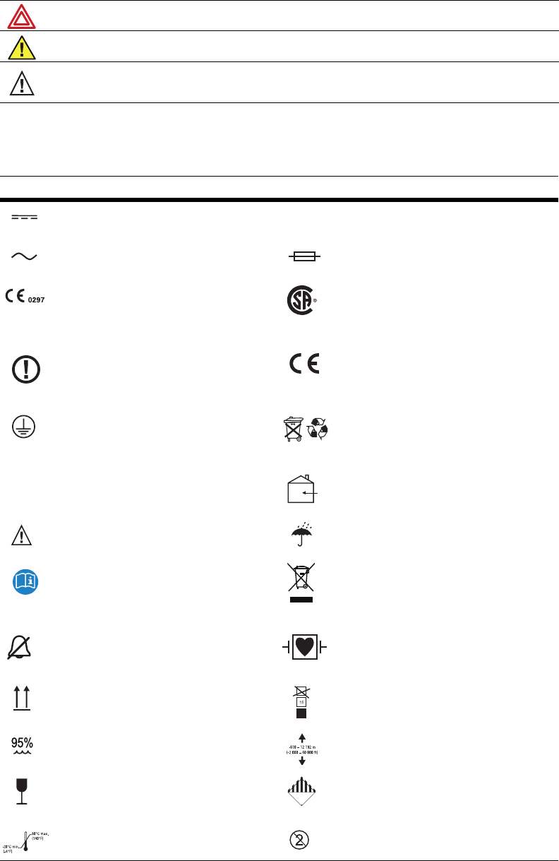
Symbols
The following symbols appear on the monitor or accessories.
Warning Warning statements in this manual identify conditions or practices that could result in personal
injury.
Caution Caution statements in this manual identify conditions or practices that could result in damage to the
equipment or other property.
Caution On the product, means “Consult the accompanying documentation.”
Symbol Definition Symbol Definition
Direct current Enclosure Protection Drip proof: Classification
IPX1 per EN60529: 1991
Alternating current (battery charger) Fuse
The CE Mark and Notified Body Registration
Number signify the device has met all essential
requirements of European Medical Device
Directive 93/42/EEC
This device has been tested and certified by
the Canadian Standards Association
International to comply with applicable U.S.
and Canadian medical safety standards.
Restrictions for use of wireless device in
Europe. European Communities Class 2 radio
equipment
Signifies the device has met all essential
requirements of European Medical Device
Directive 93/42/EEC for a Class 1 product
(battery charger)
Protective earth ground (battery charger) Separate batteries from other disposables for
recycling
Lithium Ion battery For indoor use only (battery charger)
Caution: Refer to Directions For Use and
accompanying documentation Keep away from rain
See the accompanying manual Recycle the monitor and battery
separately from other waste. Refer to
www.welchallyn.com/weee for collection
point and additional information.
Alarm(s) off Patient connections are Type CF, isolated for
direct cardiac application, and protected
against defibrillation
This way up Stacking limit (by number)
Humidity limit Altitude limit
Fragile IATA/ICAO Hazard Class 9 Package
(International Air Transport Association/
International Civil Aviation Organization)
Temperature limits Single use only
IPX1
CUS
Li+
Li++
9
Directions for Use Chapter 1 General information 3
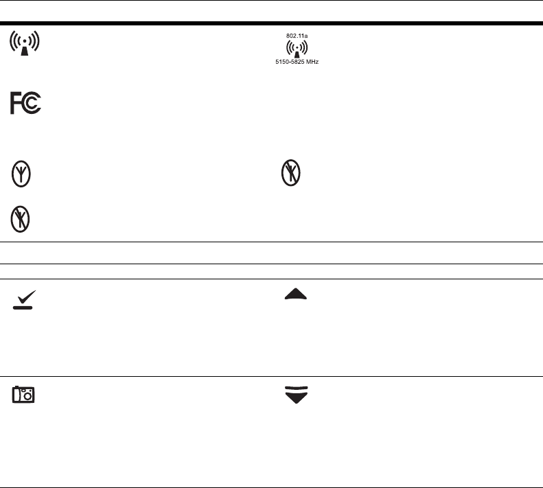
Non-ionizing electromagnetic radiation. This
device contains an approved RLAN module
frequency 2402 to 2480 MHz
Non-ionizing electromagnetic radiation. This
device contains an approved RLAN module
frequency 5150 to 5825 MHz
This device complies with the 47 CFR Part 15
radiated and conducted emissions
requirements.
The monitor is connected to Acuity The monitor is not connected to Acuity
(Flashing) The monitor is searching for a
connection to Acuity
Monitor Front Panel Keys
Select Key and Silence Patient Alarm/
Equipment Alert Key- Selects the choice
highlighted on the menu. During patient alarms,
silences the tone at the monitor and at Acuity (if
connected) for 90 seconds. During equipment
alerts, silences or acknowledges (dismisses) the
alert.
Scroll Up Key and Reset Alarm Tone Key-
Scrolls up menus on the display. During patient
alarms, resets the tone at the monitor and at
Acuity (if connected).
Snapshot Key - When connected to Acuity,
pressing this key sends Acuity a snapshot print
to the Acuity central station printer. A total of
21 seconds of patient numeric and waveform
data (14 seconds of history, 7 seconds after the
key is pressed) will be sent to the printer. See
”Snapshot key” on page 10 for more
information.
Scroll Down Key and Main Menu Key- Pressing
this key scrolls down menus on the display, or
causes the Main Menu to appear if no menu is
displayed.
Symbol Definition Symbol Definition
This device complies with FCC and
Industry Canada requirements for
international radiators (802.11 wireles
s)
FCC ID:
PGUWA11AO7
IC:
4168a-WA11A07
4Chapter 1 General information Welch Allyn Micropaq Monitor
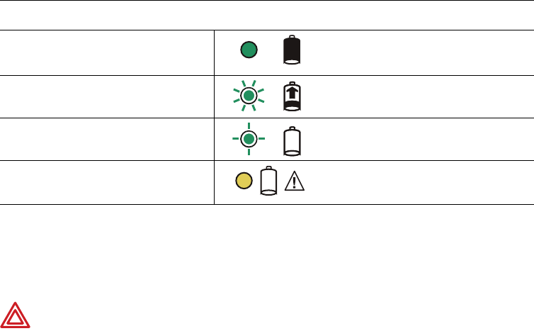
Battery charger labels and LEDs
General warnings and cautions
Familiarize yourself with all warnings and cautions before using the monitor.
Eight-bay battery charger
(008-0651-XX)
Green LED on continuously Battery is fully charged.
Green LED flashing kj Battery is charging.
Green LED flashing very slowly Battery detected and waiting to be charged.
Yellow LED on continuously Something is wrong with the battery or the
charger. (See ”Battery Status and Possible
Response” on page 44.)
WARNING When considering a treatment protocol that involves wireless
communication of patient data, be sure to recognize some limitations inherent
in wireless communications. When the monitor is not connected to the
network:
•There are no patient alarms or alerts at the Acuity Central Station.
•Acuity does not perform arrhythmia and ST analysis on the patient data
and does not generate related alarms.
•Patient data is not saved.
WARNING Do not try to monitor neonatal patients with the monitor. The
monitor is intended for adult or pediatric patients. It is not intended for use with
pediatric patients (or infants) weighing less than 22 lbs (10 kg).

Directions for Use Chapter 1 General information 5
WARNING Always check the patient mode at Acuity when monitoring a new
patient. The patient mode determines default alarm limits and internal algorithm
settings.
WARNING The monitor may not meet its performance specifications if stored
or used outside the specified temperature and humidity ranges.
WARNING Do not connect more than one patient to a monitor. Do not connect
more than one monitor to a patient.
WARNING During defibrillation, keep the discharge paddles away from ECG
and other electrodes, as well as other conductive parts in contact with the
patient.
WARNING Do not operate this product in the presence of flammable
anesthetics or other flammable substances in combination with air, oxygen-
enriched environments, or nitrous oxide; explosion can result.
WARNING Do not use the monitor in a Magnetic Resonance Imaging (MRI)
suite or a hyperbaric chamber. Such use can cause fire or explosion resulting in
patient injury and monitor damage.
WARNING Electronic equipment that emits strong electromagnetic or radio
frequency signals can cause electrical interference with monitor operation. This
interference may distort the ECG signal, thereby preventing accurate rhythm
analysis. Avoid operating this device near equipment of this type.
WARNING Exposure to Radio Frequency (RF) radiation. To comply with Federal
Communications Commission (FCC) RF exposure requirements, this device
shall be used in accordance with the operating conditions and instructions
provided in this manual, including the section ”Install the carrying pouch” on
page 28.
WARNING Pacemaker signals can differ from one pacemaker to the next. The
Association for Advancement of Medical Instrumentation (AAMI) cautions that
“in some devices, rate meters may continue to count the pacemaker rate during
occurrences of cardiac arrest or some arrhythmias. Do not rely entirely upon rate
meter alarms. All pacemaker patients should be kept under close or constant
observation.” See ”ECG specifications” on page 51 for disclosure of the
pacemaker pulse rejection capability of this instrument.
WARNING This wireless medical device was tested and, when used with a
metal-free accessory between the monitor and the patient, complies with FCC
RF Exposure (SAR) guidelines. The use of accessories containing metal may not
ensure compliance with FCC RF exposure guidelines. Specific Absorption Rate
(SAR) is a measurement of radio frequency energy. The FCC permits a
maximum SAR value of 1.6 mW/g. The highest SAR value for this patient
monitor, when worn by a patient in accordance with the directions for use, is
0.560 mW/g.
WARNING High-power radars are allocated as primary users of the 5.25 to
5.35 GHz and 5.65 to 5.85 GHz bands. These radar stations can cause
interference with and/or damage this device.
WARNING Changes or modifications not expressly approved by Welch Allyn
could void the purchaser’s authority to operate the equipment. This product
does not contain any user serviceable components. Any unauthorized product
changes or modifications will invalidate Welch Allyn’s warranty and all applicable
regulatory certifications and approvals.

6Chapter 1 General information Welch Allyn Micropaq Monitor
It is possible for the monitor to detect a problem that prevents the monitor from operating
properly. If this occurs, the monitor displays an error message and error number. Report
such errors to Welch Allyn. The monitor should be serviced only by a Welch Allyn service
technician while under warranty. Contact Welch Allyn for information about post-warranty
period service.
WARNING For patients with a pacemaker, position the monitor to maintain a
minimum 6-inch distance between the monitor and pacemaker. Immediately
turn the monitor off and provide appropriate patient care if you have any reason
to suspect that the monitor is interfering with the pacemaker. The Health
Industry Manufacturers Association recommends this minimum 6-inch distance
between a hand-held wireless radio and a pacemaker, which is consistent with
the independent research by, and recommendations of, Wireless Technology
Research.
WARNING Make frequent electrical and visual checks on cables, sensors, and
electrode wires. All cables, sensors, and electrode wires must be inspected and
properly maintained and in proper working order to allow the equipment to
function properly and protect patient safety.
WARNING Avoid electrosurgery burns at monitoring sites by ensuring proper
connection of the electrosurgery return circuit so that the return paths cannot be
made through monitoring electrodes and probes.
WARNING Use of ECG and SpO2 cables not specified by Welch Allyn may
negate defibrillator protection and risk patient injury.
WARNING Use of Masimo LNOP® sensors/cables will not provide protection
in accordance with IEC defibrillation standards when used with this device.
WARNING To ensure patient safety, the conductive parts of the ECG
electrodes (including associated connectors) and other patient-applied parts
should not contact other conductive parts, including earth ground, at any time.
WARNING Motion artifact can affect the accuracy of patient vital sign
measurements. Minimize patient motion whenever possible.
WARNING Use only accessories supplied by Welch Allyn or recommended in
the Welch Allyn Products and Accessories booklet (810-0409-XX). The monitor
will only meet the listed specifications when using accessories listed by Welch
Allyn. Use accessories according to your facility’s standards and the
manufacturer’s recommendations. Always refer to the manufacturer’s Directions
for Use.
WARNING As with all medical equipment, carefully route the patient cabling to
reduce the possibility of patient entanglement or strangulation. Use the supplied
garment clips to secure the cable properly.
WARNING When positioning the monitor pouch on the patient, make sure the
straps do not entangle the patient’s neck or cause choking. Make sure the straps
do not restrict the movement of the patient’s limbs or create a hazard when
walking or moving.
WARNING If a product has been dropped or severely abused, send it to a
qualified service person to confirm proper operation.
Caution Do not autoclave the monitor. Autoclave accessories only if the
manufacturer’s instructions clearly approve it. Many accessories can be severely
damaged by autoclaving.
Directions for Use Chapter 1 General information 7
Introducing the monitor
The monitor is a patient-worn vital signs monitor for use by adult or pediatric ambulatory
patients.
• One or two ECG channels displayed
• Up to 2 ECG leads displayed at the monitor:
I, II, III, V, aVR, aVL, or aVF with 5-lead cable
• Up to 7 ECG leads displayed at Acuity:
I, II, III, V, aVR, aVL, or aVF with 5-lead cable
• One ECG lead displayed at the monitor and
at Acuity: Fixed lead II with 3-lead cable, or
5-lead cable with only RA, LA and LL
electrodes attached.
• Pulse oximetry (SpO2) monitoring (Model
408 only)
• Two-way wireless communication within
Welch Allyn’s FlexNet network
• LCD for display of ECG waveforms, SpO2
and heart rate/pulse rate data, and
messages from Acuity
• Standalone operation with patient alarms
when out of range of the network
• Patient alarm limits that can be set at the
monitor or at Acuity
• Configurable formats for single- or dual-waveform ECG display
• Internal antenna
• Snapshot key
• Lightweight (less than two pounds with battery)
• Rugged and tolerant of brief water exposure
• Rechargeable battery
• Sleep mode to extend battery life
• Your model may be shipped with an attached identification number on the front of the
monitor.
Model 406
ECG monitoring
Model 408
ECG monitoring and either one of two pulse oximetry (SpO2) monitoring options:
•SpO
2 with Masimo® SET® technology, indicated by:
•SpO
2 with NELLCOR® OxiMax™ technology, indicated by:
8Chapter 1 General information Welch Allyn Micropaq Monitor
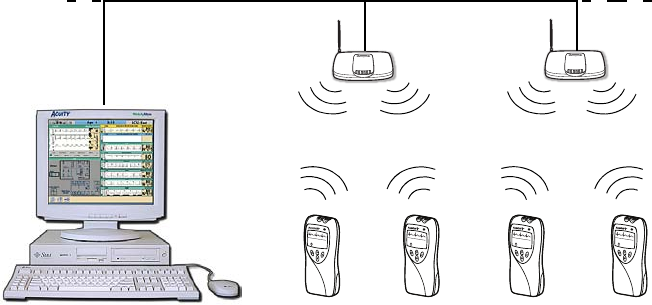
Understanding the monitor and the FlexNet Network
The monitor is intended to operate with an Acuity® Central Station as part of Welch Allyn’s
FlexNet network. FlexNet allows multiple devices to communicate through hardwired
Ethernet networks and Wireless Local Area Networks (WLANs). The Acuity Central
Station provides the primary display and entry of patient data for a patient connected to
the monitor.
Each patient-worn monitor supports two-way communication with an Acuity Central
Station through an access point in the FlexNet network. The access point is a digital radio
transceiver that connects to the FlexNet network. During monitoring, the monitor sends
the patient data to Acuity. Acuity and the monitor continuously analyze the data. Acuity
provides appropriate alarm or alert messages at the Central Station and other network
devices such as a hallway message panel and the monitor itself. Acuity also stores the
patient data for viewing or report printing.
If the monitor is moved out of range or loses communication with the FlexNet network
and Acuity, it continues to monitor the patient and display patient data. While not
communicating with Acuity, the monitor continues to generate local patient alarms or
alert messages. Patient data is not stored and Acuity does not perform waveform analysis
or generate arrhythmia messages while the monitor is not communicating with Acuity.
When the monitor is returned to within range of the FlexNet network, it automatically
reconnects to Acuity.
HRSpO2
80 97
FlexNet Network
Micropaq monitors
Access Points
To Other
Access
Points
To Other Acuity
Central Stations
Acuity Central Station
HRSpO2
80 97
HRSpO2
80 97
HRSpO2
80 97
Directions for Use Chapter 1 General information 9
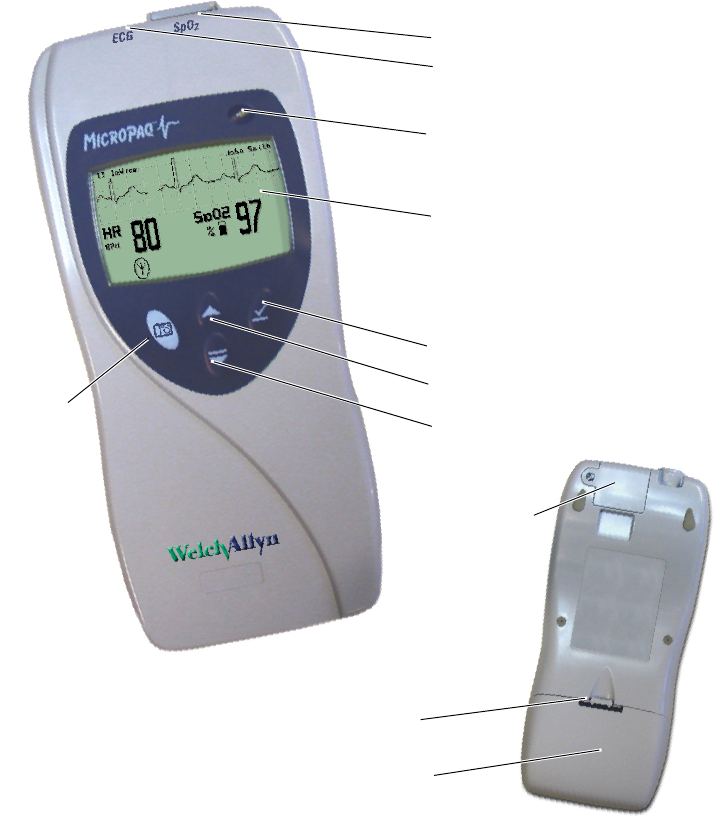
Monitor features
Controls and connectors
SpO2 Connector
ECG Connector
Visual Alarm Indicator
Liquid Crystal Display
Snapshot key Scroll Up Key and Reset Patient Alarm Tone Key
Scroll Down Key and Main Menu Key
Select Key and
Silence Patient Alarm/
Equipment Alert Key
Back
Battery pack latch
Battery
SpO2
connector clip
(model 408) or
cover (model
406)

10 Chapter 1 General information Welch Allyn Micropaq Monitor
Visual alarm indicator
Audible alarm indicator
Beeps to indicate a patient alarm, and beeps faster for life-threatening arrhythmia
alarms (see ”Patient alarm and equipment alert specifications” on page 56).
Beeps to indicate when the equipment needs attention. This beep tone is slower than
patient alarm tones (see ”Patient alarm and equipment alert specifications” on
page 56).
Volume can be configured as high, low, or off (configured at Acuity).
Volume can be configured differently for network connection or stand-alone operation
(configured at Acuity).
Snapshot key
When connected to Acuity, pressing this key sends a snapshot of the patient’s
numeric and waveform data to the Acuity Central Monitoring System. Depending on
how Acuity is configured, this will cause Acuity to print a 21-second snapshot (14
seconds of history, 7 seconds of data after the button is pressed) to the Acuity central
station printer.
Scroll Up key and Reset Patient Alarm Tone key
Scrolls up menus on the display.
Resets a silenced patient alarm tone.
Green Flashes slowly during normal operation.
Red Flashes during patient alarm, remains on continuously when alarms
are silenced or suspended.
Yellow Flashes during an equipment alert or while not connected to the
network.
Remains on continuously if the operator suspends an alert at Acuity
for 90 seconds or acknowledges (dismisses) a low battery alert from
the monitor or Acuity.
Note
The flashing green LED indicates that the monitor is connected to the network
but not necessarily connected to a patient. If the monitor is actively monitoring a
patient, the green LED indicates no alarms or alerts are detected.
Note
Snapshot is the default selection of the monitor. However, the connected
monitor will inherit the configuration previously defined by Acuity. For example,
if Acuity has defined the Snapshot key to respond with a Nurse Call function and
a new monitor is introduced to the system, the Snapshot key definition will
remain as Nurse Call.
For more information about using the Acuity Central Monitoring System, refer to
Acuity Directions For Use (810-1605-XX)

Directions for Use Chapter 1 General information 11
Scroll Down key and Main Menu key
Scrolls down menus on the display.
Displays the Main Menu.
Select key and Silence Patient Alarm/Equipment Alert key
Selects the choice highlighted on the menu.
During patient alarms, silences the tone at the monitor and Acuity (if connected) for
90 seconds. During equipment alerts, silences or acknowledges (dismisses) the alert
at the monitor and Acuity.
Battery
Insert the battery to turn on power. Remove the battery to turn off power. (While the
battery is removed, the monitor does not perform patient monitoring.)
Recharge the battery while it is removed from the monitor. (See ”Recharge a battery”
on page 43.)
To order a new battery, see ”Battery Status and Possible Response” on page 44.
Note
If you do not use END TELE to disconnect from the network as described
above, the Acuity Central Station generates a DROPOUT equipment alert at
Acuity.
If you want to monitor this same patient at a later time, you will need to reselect
the patient name from the monitor or confirm the patient ID at Acuity.
12 Chapter 1 General information Welch Allyn Micropaq Monitor
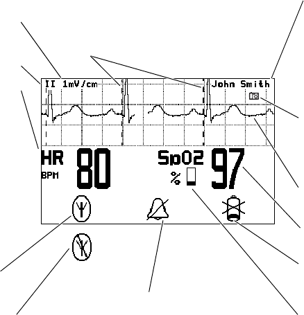
Display
Although the Acuity Central Station is the primary location for viewing patient data, the
monitor provides information to support patient care.
Display sleep mode
In order to extend battery life, the display becomes blank after two minutes if no keys are
pressed. The display becomes active again if an alarm or alert occurs, a key is pressed,
the initial Acuity connection occurs, a cable is inserted, or an electrode is attached.
The display will not become blank if a patient alarm is occurring, an Acuity message is
displayed, or the monitor is in Demo mode or Service mode.
Patient name as entered at
Acuity.
If the patient name has not
been entered, the monitor
displays the last four digits of
the monitor serial number, suc
h
as: ID:6472
SpO2 numeric data is a
percentage value.
HR indicates the heart
rate is from ECG.
PR (pulse rate) is
displayed if SpO2 is active
and ECG is not (pulse rate
is derived from SpO2).
If the monitor detects
a vital sign outside
the measurable range,
it displays:
- - - (below the range)
+ + + (above the range).
ECG lead is selectable
Low battery icon flashes to
indicate monitor will shut off i
n
30 minutes or less.
Indicates the monitor
is connected to
Acuity.
Waveform scale is
selectable
Indicates one or
more patient alarms
are disabled (off).
ECG waveform is displayed
when active.
Dashed lines indicate the
monitor detects a pacemaker
signal (display of pacer
detection can be enabled or
disabled at Acuity)
T
his symbol indicates the monitor is not
c
ommunicating with Acuity:
F
lashing indicates the monitor is associated
w
ith an access point, but not communicating
w
ith Acuity.
C
ontinuous on indicates the monitor is not
c
ommunicating with an access point or Acuity.
Symbol is displayed at the
monitor whenever the
Snapshot key is pressed.
SpO2 pulse amplitude indicato
r
(not proportional to pulse
volume)
Directions for Use Chapter 1 General information 13
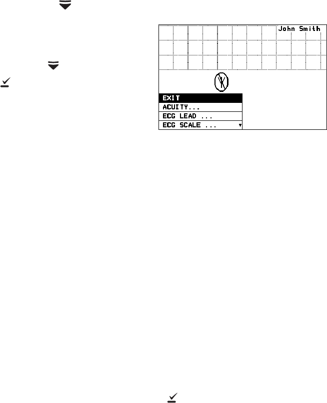
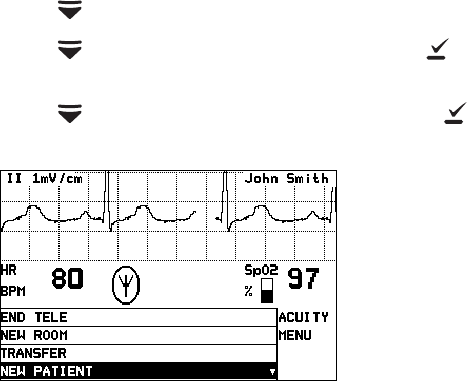
Main Menu
When you first press , the Main Menu appears:
EXIT Exit the Main Menu (the menu disappears).
ACUITY... Access the Acuity Menu with network options. The Acuity Menu
is only accessible while connected to Acuity.
EXIT Exit all menus and return to the monitoring
screen.
END TELE Discontinue monitoring a patient.
NEW ROOM Reassign a patient to a new room in the same
unit.
TRANSFER Transfer a patient to a new room in a new unit.
NEW PATIENT Assign the monitor to a new patient.
PATIENT INFO Display patient information such as ID, name,
unit and room.
Whenever the monitor is connected to Acuity and you select
ACUITY... from the Main Menu, the monitor displays the message
ACUITY CONTACTED to confirm that Acuity has been contacted.
The monitor continues to display this message until Acuity
responds, or you press to acknowledge the message and clear
the screen. If the monitor detects an alarm or alert, it clears the
screen to display the appropriate alarm or alert message. The
length of time required for Acuity to respond to your selection at
the monitor can vary widely depending on the amount of network
traffic and other conditions.
ECG LEAD... Access a menu to change the ECG 1 or ECG 2 lead selection (I, II,
III, aVR, aVL, aVF, or V). Available vectors depend on the connected
electrodes.
Press to select or change the highlighted choice.
Press to move through the menu.

14 Chapter 1 General information Welch Allyn Micropaq Monitor
ECG SCALE... Change the scale of the ECG waveform. If two waveforms are
displayed, both have the same scale.
1 WAVEFORM There are four possible ECG waveform display selections:
1 WAVEFORM the default selection
2 WAVEFORMS
5 SECONDS
FULL SCREEN
Pressing changes to the next selection. This change does not
take effect until after you exit the Main Menu. See ”Display” on
page 12 for descriptions.
LIMITS... Enter the Alarm Limits Menu (”Customize patient alarm limits at
the monitor” on page 37) and change alarm limits.
SYSTEM
INFORMATION Display information about the network connection and SpO2
module.
SERVICE MENU Enter Service Mode for a demonstration mode (Demo, see
”Demonstration mode” on page 17) or service functions for
technicians. Service Mode is not available if any cables are
plugged in.
Note
To restrict access to the Main Menu, a Menu Lock option can be configured for
the monitor at the Acuity Central Station. When the Menu Lock is enabled, the
operator must press and hold down and for two seconds to gain access
to the Main Menu. The Menu Lock is disabled if the monitor loses
communication with Acuity.
Directions for Use Chapter 1 General information 15
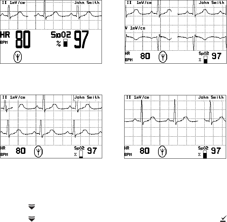
Waveform options
There are four ECG waveform options as shown:
To change the waveform selection during operation:
1. Press to display the Main Menu.
2. Press as needed to highlight the current waveform selection. Then press as
needed to select the desired display.
1 Waveform
The single ECG 1 (lead II)
waveform is displayed.
Full Screen
The single ECG 1 (lead II) waveform is
allowed to occupy most of the screen.
2 Waveforms
ECG 1 (lead II) and ECG 2
(lead V) are both displayed.
5 Seconds
ECG 1 (lead II) cascades from
one line to the other.

16 Chapter 1 General information Welch Allyn Micropaq Monitor
Messages from Acuity
The monitor displays messages sent from Acuity as needed, including patient alarms and
equipment alerts. When Acuity messages are displayed, they temporarily override
information displayed on the lower half of the monitor screen.
Accessories
Operating settings
The following monitor operating settings can be set at the monitor or at the Acuity Central
Station:
• Patient alarm limit settings (ECG and SpO2).
• ECG lead and scale selection
• ECG display format
Many other monitor operating settings (such as patient mode and alarms volume) can
only be set at the Acuity Central Station. See ”Operating settings” on page 49 for a list of
all settings and where they are set.
Default settings
When the monitor connects to Acuity for a new patient, the Acuity Central Station
downloads the appropriate default settings stored at Acuity. While the monitor is
connected to Acuity, settings can be changed either at the monitor or at the Acuity Central
Station.
If the monitor is temporarily disconnected from Acuity and the operator changes settings
at the monitor, those settings are transmitted to and stored at Acuity when the monitor
reconnects.
Battery charger (8-battery) Micropaq Directions For Use
Battery ECG electrodes
3-lead ECG cable (optional) 5-lead ECG cable
ECG extension cable (optional) Carrying pouch
SpO2 sensors (Masimo or Nellcor) SpO2 cable (Masimo or Nellcor)
WARNING Use only accessories supplied by Welch Allyn or recommended in
the Welch Allyn Products and Accessories booklet (810-0409-XX). The monitor
will only meet the listed specifications when using accessories listed by Welch
Allyn. Use accessories according to your facility’s standards and the
manufacturer’s recommendations. Always refer to the manufacturer’s Directions
for Use.
Directions for Use Chapter 1 General information 17
Demonstration mode
You can practice using the monitor with the Demo mode of operation, including
connection to Acuity.
The Demo mode cannot be activated while you are monitoring a patient or if any cables
have been plugged into the monitor. During the Demo mode, the monitor and Acuity
display the message SIMULATION.
To practice with the monitor in Demo mode:
1. Disconnect all patient cables connected to the monitor.
2. Remove the battery (if installed).
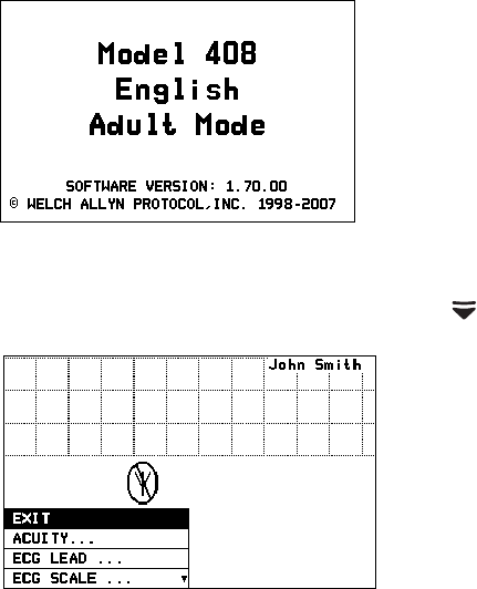
3. Insert the battery and watch for the Power-Up screen.
4. After the Power-Up screen disappears, press to display the Main Menu.
Power-Up Screen
Main Menu
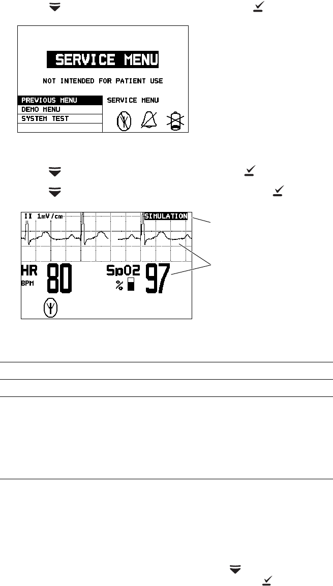
18 Chapter 1 General information Welch Allyn Micropaq Monitor
5. Press to highlight SERVICE MENU, then press to display the Service Menu.
6. Press to highlight DEMO MENU, then press to display the Demo Menu.
7. Press to highlight DEMO 1 or DEMO 2, then press to start.
8. While in Demo mode you can practice changing settings such as ECG lead selection
and alarm limit adjustment. (These changes only affect the Demo mode and are
erased when you exit the Demo mode.)
9. To change to the other Demo selection, press to display the menu, then scroll
down to highlight TOGGLE DEMO MODE and press .
10. To exit the Demo mode, either insert a patient cable or remove and insert the battery.
The monitor restarts and enters the normal monitoring mode.
Demo Mode Display Values and Alarm Limits
Display Demo 1 Demo 2a
a. Demo 2 will cause patient alarms.
Alarm Limits (On)
ECG Waveform Normal sinus rhythm,
normal ST Normal sinus rhythm,
normal ST (not applicable)
ECG Heart Rate
SpO2 Pulse Rate 80 125 Lower 50
Upper 120
SpO2 Saturation% 97 88 Lower 90
Upper 100
Service Menu
A simulated waveform and
numerics are displayed.
Demonstration Mode
SIMULATION indicates the
Demo mode is active.
2
19
Monitoring
Connect a new patient
Connect to the network
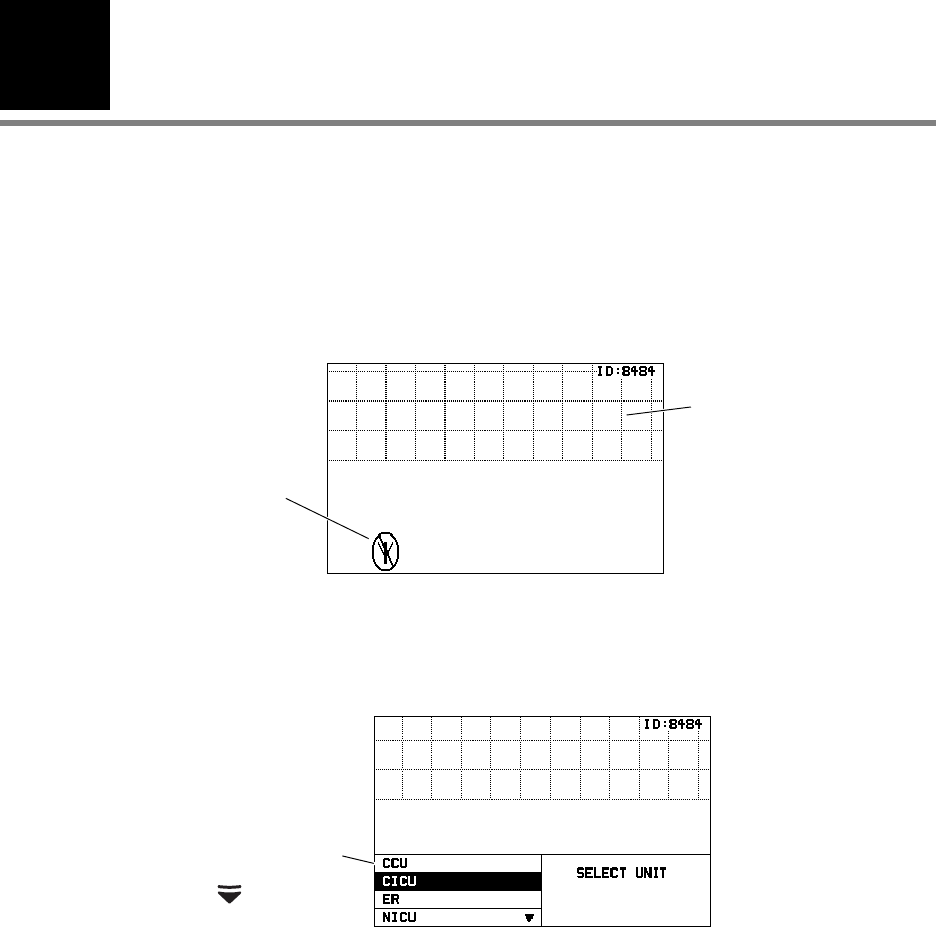
1. Insert a battery into the monitor to turn it on. After a few seconds the monitor Power-
Up Screen is replaced by an initial monitoring screen.
2. After the network connection is established, the monitor may prompt you to select an
Acuity Unit (if your facility has more than one Acuity unit):
If any patient cables are
connected, there will be
some patient data displayed.
The format depends on the
monitor default settings.
Example of Initial Monitor Screen
The monitor is
searching for a
network
connection.
Possible Acuity Unit
selections.
Press to view more.
Example of Acuity Unit Selection
20 Chapter 2 Monitoring Welch Allyn Micropaq Monitor
3. Press or to highlight the desired Acuity unit, then press .
When you press or to highlight the desired Acuity unit and then press ,
your selection will begin to flash between normal and reverse video to confirm that
the monitor is communicating your selection to Acuity. You cannot scroll to another
selection during this time. The selection continues to flash until Acuity responds back
to the monitor. Then the monitor displays the next appropriate screen (such as a list of
possible patients). The length of time required for Acuity to respond to your selection
at the monitor can vary widely depending on the amount of network traffic and other
conditions.
Be sure to select an Acuity unit. Even though the monitor is
connected to the network (as indicated by the green LED and
network connection symbol), the Acuity Central Station may not
display any indication of this monitor until after you have selected an
Acuity unit.
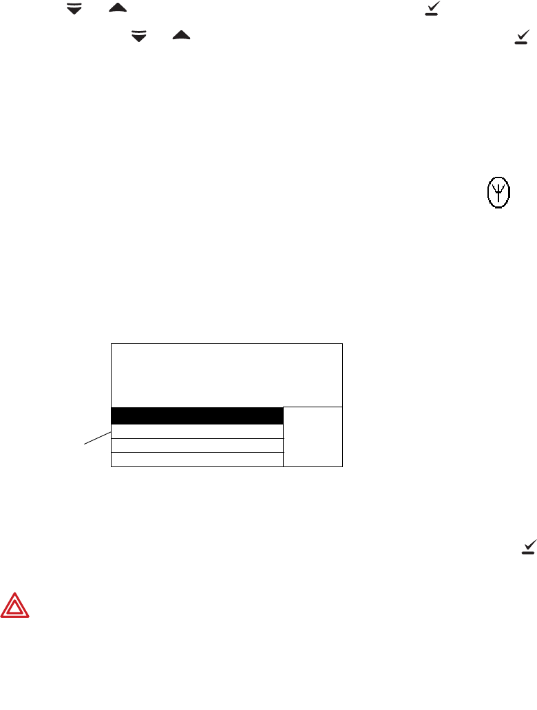
4. The monitor displays a list of possible patients.
If your patient has been pre-admitted to the selected Acuity unit, they will be included
in the list.
5. Scroll through the patient list to look for your patient’s name.
• If your patient is not in the list, highlight Select Patient at Central and press .
The patient name will need to be entered later at the Acuity Central Station.
WARNING If you do not select the patient name at the monitor at this time, do
not adjust any alarm limits until after the patient name and ID are confirmed at
Acuity. When the patient name and ID are confirmed at Acuity, Acuity
downloads the default settings and patient alarm limits for that Acuity unit to the
monitor, thereby overriding any previous settings and alarm limits.
Note
At power-up, the monitor retains the most recent patient mode. The patient
mode can only be changed at Acuity. If the patient is being monitored when the
patient mode is changed, there is a brief interruption in the display and recording
of ECG and SpO2 patient data.
Network Connectio
n
Symbol
Possible
patients to
select. Example of Patient List
SELECT
PATIENT
428-02-2392, Hopkins, Bill J
520-29-0319, Phillips, Mary L
532-94-8372, Smith, Frank R ▼
Select Patient at Central
Directions for Use Chapter 2 Monitoring 21
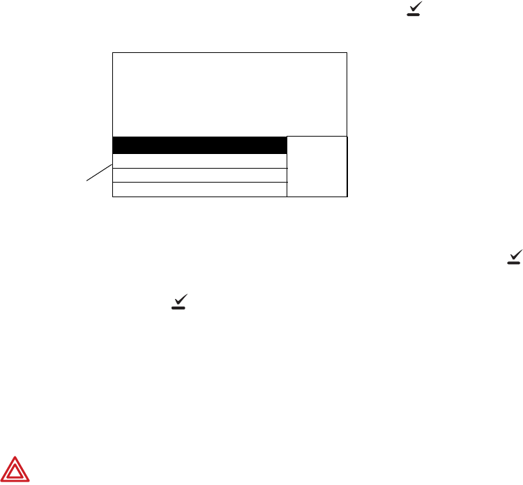
• If your patient is in the list, highlight the name and press . Within a few
seconds the monitor displays a list of unassigned rooms.
• If you want to assign the patient to a room, highlight the room and press .
• If you do not want to assign a room at this time, highlight Select Room at
Central and press . The patient room will need to be entered later at the
monitor (see “Reassign a monitored patient to a new room in the same unit” on
page 32) or at Acuity (see “Monitor patient at Acuity” on page 41).
6. If you need to customize alarm limits for your patient, see “Customize patient alarm
limits at the monitor” on page 37.
Perform ECG monitoring
Possible
rooms to
select. Example of Room List
SELECT
ROOM
1104A
1104B
1105A
Select Room at Central
▼
WARNING Motion artifact can cause incorrect heart rate readings. Minimize
patient motion whenever possible.
WARNING If a disconnected lead is in too close proximity to other electrical
devices, it may cause false heart rate readings.
WARNING The monitor does not provide internal arrhythmia analysis.
Therefore, arrhythmias may cause the monitor to display inaccurate heart rates.
WARNING The monitor will show + + + for HR numerics between 301 and
350 beats per minute. Above 350 beats per minute, it may display incorrectly
low heart rates, due to intermittent picking of R-waves.
WARNING Do not use the monitor in a Magnetic Resonance Imaging (MRI)
suite or a hyperbaric chamber. Such use can cause fire or explosion resulting in
patient injury and monitor damage.
WARNING Pacemaker signals can differ from one pacemaker to the next. The
Association for Advancement of Medical Instrumentation (AAMI) cautions that
“in some devices, rate meters may continue to count the pacemaker rate during
occurrences of cardiac arrest or some arrhythmias. Do not rely entirely upon rate
meter alarms. All pacemaker patients should be kept under close or constant
observation.” See “ECG specifications” on page 51 for disclosure of the
pacemaker pulse rejection capability of this instrument.

22 Chapter 2 Monitoring Welch Allyn Micropaq Monitor
• Even though the monitor contains fully isolated patient-connected circuitry, it has not
been specially designed for direct application on a patient’s heart.
• Use only with accessories provided or recommended in the Welch Allyn Products and
Accessories booklet (810-0409-XX).
• Severe artifact and interference (such as defibrillation interference) can cause the
waveform to move off the display for a few seconds before it is restored.
WARNING For patients with a pacemaker, position the monitor to maintain a
minimum 6-inch distance between the monitor and pacemaker. Immediately
turn the monitor off and provide appropriate patient care if you have any reason
to suspect that the monitor is interfering with the pacemaker. The Health
Industry Manufacturers Association recommends this minimum 6-inch distance
between a hand-held wireless radio and a pacemaker, which is consistent with
the independent research by, and recommendations of, Wireless Technology
Research.
WARNING High-intensity radio frequency (RF) energy from external sources,
such as an improperly connected electrosurgical unit, can induce heat into
electrodes and cables which can cause burns on the patient. Reading errors and
damage to equipment may also result. This hazard can be reduced by (1)
avoiding the use of small ECG electrodes, (2) selecting ECG electrode
attachment points remote from the surgical site and from the electrosurgical
return electrode, (3) using electrosurgical return electrodes with the largest
practical contact area, and (4) assuring proper application of the electrosurgical
return electrode to the patient.
WARNING Verify patient mode at Acuity. Incorrect patient mode may result in
inaccurate heart rates and inappropriate alarm settings.
WARNING To help prevent injury, use the provided garment clips to route the
ECG cables away from the patient’s head.
WARNING Use of ECG cables with loose or faulty detachable lead wires may
cause erratic behavior of the ECG waveform due to intermittent ECG lead wire
connections.
WARNING To ensure patient safety, the conductive parts of the ECG
electrodes (including associated connectors) and other patient-applied parts
should not contact other conductive parts, including earth ground, at any time.
Caution To protect the monitor from damage during defibrillation, for accurate
ECG information, and for protection against noise and other interference, use
only ECG electrodes and cables specified or supplied by Welch Allyn (these
cables have the required current-limiting resistors). Follow recommended
application procedures.
Caution Do not use an ECG cable longer than 10 feet (3 meters). If the nominal
length of the ECG cable, including extensions, exceeds this length, the monitor
is not guaranteed to meet published electromagnetic compatibility (EMC)
performance specifications.
Directions for Use Chapter 2 Monitoring 23
Perform 5-Lead ECG monitoring
1. Inspect the ECG cable and replace it if it shows any signs of wear, breakage, or
fraying. Plug the cable into the monitor.
2. Select electrode sites on the patient.
Choose flat areas; avoid fatty or bony areas and major muscles.
3. Shave or clip hair from electrode sites, thoroughly clean skin, and lightly rub dry.
You may use soap and water, isopropyl alcohol or special skin preparation pads. To
avoid allergic reactions to electrodes, refer to the electrode manufacturer’s directions.
4. If you are using pre-gelled electrodes, make sure the electrode date is not expired and
the gel is intact and not dried out. For best results, use only silver/silver chloride
electrodes.
If you are using ungelled electrodes, apply a 1/4- to 1/2-inch mound of gel over the
electrode contact area.
For best product performance and measurement accuracy, do not use stainless steel
needle electrodes, squeeze bulb electrodes, or electrodes with dissimilar metals. Due
to polarization, such electrodes can generate offsets beyond the monitor’s
capabilities. Do not use electrodes from more than one manufacturer on the same
patient.
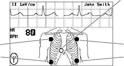
5. Attach lead wires to the electrodes before applying them to the patient. Apply the
electrodes to the patient in the proper locations.
If the monitor detects that some lead wires are not properly connected, the monitor
displays a chest diagram and indicates which leads are disconnected.
The locations of the circles displayed on the monitor for each lead are fixed, and are
not affected by the exact placement of the electrodes on the patient. For example,
the C lead can be placed on the patient in any one of the V1-V6 locations desired, but
will only be displayed on the monitor in the location shown above.
Flashing circle indicates the
lead is not connected.
Left ArmRight Arm
Left Leg
Right Leg

24 Chapter 2 Monitoring Welch Allyn Micropaq Monitor
6. After leads are properly connected, confirm that the monitor displays the ECG
waveform, heart rate, and other patient data.
To change the ECG lead selection, press to display the Main Menu. Then press
Scroll Down to highlight ECG LEAD . . . , then highlight ECG 1 or ECG 2 and press
to change the lead.
3-Lead ECG application with the 5-Lead ECG cable
You can perform 3-lead ECG monitoring in a similar manner as 5-lead ECG monitoring. You
may use the 5-lead ECG cable with detachable electrode lead wires, and connect only the
lead wires and electrodes for RA, LA, and LL. Refer to the Welch Allyn Product and
Accessories booklet (810-0409-XX) for part numbers.
Follow these steps:
1. Pe r f o r m Step 1 through Step 4 on page 23 as described for 5-lead ECG monitoring.
2. Before attaching electrodes to the patient, attach only lead wires for RA, LA, and LL to
the 5-lead ECG trunk cable and to the electrodes. Make sure that lead wires for C and
RL are DETACHED from the 5-lead ECG trunk cable.
3. Apply the electrodes for RA, LA, and LL to the patient in the proper locations.
The monitor displays the chest diagram with two circles blinking confirming that the C
and RL electrodes are not connected.
4. Observe the monitor and visually confirm that within about 30 seconds, the two
circles disappear and the monitor displays the ECG waveform, heart rate, and other
patient data.
Be aware that if you connect the C or RL lead wires to the 5-lead ECG trunk cable and
apply the C or RL electrodes to the patient, the monitor defaults to 5-lead ECG
monitoring and does not enable 3-lead ECG monitoring. To enable 3-lead ECG
monitoring, you must disconnect the ECG cable from the monitor for a few seconds,
and then begin this procedure again.
Note
Be aware that there are some inherent limitations with this application,
especially when compared to 5-lead ECG monitoring. These limitations include
the restriction to only one displayed lead, ECG lead II. Because only one
displayed lead is available (ECG lead II), factors such as a poor electrode
connection at RA, LA, or LL can significantly affect performance. To overcome
these limitations, the 5-lead ECG monitoring is preferred.
The monitor’s 3-lead ECG monitoring is only available for use with Acuity
software versions 6.1 or later.

Directions for Use Chapter 2 Monitoring 25
Be aware that only ECG lead II is available for display with the monitor’s 3-lead ECG
monitoring. No other ECG lead selections are available.
3-Lead ECG application with the 3-Lead ECG cable
Refer to the Welch Allyn Product and Accessories booklet (810-0409-XX) for part numbers.
Follow these steps:
1. Pe r f o r m Step 1 through Step 4 on page 23 as described for 5-lead ECG monitoring.
2. Attach lead wires to the electrodes before applying them to a patient.
3. Apply the electrodes for RA, LA, and LL to the patient at the proper locations. If the
monitor detects one of the lead wires is not properly connected, it will display a chest
diagram indicating which lead is disconnected.
4. Observe the monitor and visually confirm it displays the ECG waveform, heart rate,
and other patient data.
Be aware that only ECG lead II is available for display with the monitor’s 3-lead
monitoring. No other ECG lead selections are available. The monitor will not detect
the presence of a 3-lead cable until two or more of its leads are connected to the
patient.
3-Lead ECG application with the 3-Lead ECG cable and cable extension
This combination functions the same way as the 3-lead ECG application with the 5-lead
cable. For electromagnetic compatibility (EMC) reasons, do not use an ECG cable and
extension cable length of more than approximately 10 feet total.
WARNING Do not try to perform this 3-lead ECG monitoring with any 5-lead
ECG cable that does not have detachable electrode lead wires as described
above. Attempting to perform this procedure with a 5-lead ECG cable which has
lead wires cut off or hanging loose and not connected to the patient would
present a shock hazard to the patient or clinician.
Note
Be aware there are some inherent limitations with this application, especially
when compared to 5-lead ECG monitoring. These limitations include the
restriction to only one displayed lead, ECG II lead. Because only one displayed
lead is available (ECG lead II), factors such as poor electrode connection at RA,
LA, or LL can significantly affect performance. To overcome these limitations,
the 5-lead ECG monitoring is preferred.
The monitor’s 3-lead ECG monitoring is only available for use with Acuity
software versions 6.1 or later.

26 Chapter 2 Monitoring Welch Allyn Micropaq Monitor
Perform SpO2 monitoring
WARNING Oxygen saturation measurements using pulse oximetry are highly
dependent on proper placement of the sensor and patient conditions. Patient
conditions such as shivering and smoke inhalation may result in erroneous
oxygen saturation readings. If pulse oximetry measurements are suspect, verify
the reading using another clinically accepted measurement method, such as
arterial blood gas measurements on a co-oximeter.
WARNING Use only accessories as listed in the Welch Allyn Products and
Accessories booklet (810-0409-XX). Use only Masimo accessories and sensors
with the Masimo SpO2 option. Use only Nellcor accessories and sensors with
the Nellcor SpO2 option. The monitor will only meet the listed specifications
when using accessories listed by Welch Allyn.
WARNING Use of Masimo LNOP® sensors/cables will not provide protection
in accordance with IEC defibrillation standards when used with this device.
WARNING Tissue damage can be caused by incorrect application or use of a
sensor (e.g., wrapping the sensor too tightly, applying supplemental tape, failing
to periodically inspect the sensor site, leaving a sensor on too long in one place).
Refer to the Directions for Use provided with each sensor for specific
instructions on application and use, and for description, warnings, cautions, and
specifications.
WARNING Sensors exposed to ambient light while not applied to a patient can
exhibit semi-normal saturation readings. Be sure the sensor is securely placed
on the patient and check its application often to ensure accurate readings.
WARNING Inaccurate measurements may be caused by venous pulsations.
WARNING The pulse oximeter can be used during defibrillation, but the
readings may be inaccurate for a short time.
WARNING The pulse oximeter should NOT be used as an apnea monitor.
WARNING A very sudden and substantial change in pulse rate can result in
erroneous pulse rate readings. Be sure to validate the patient data and patient
condition before intervention or change in patient care.
WARNING Interfering Substances: Carboxyhemoglobin may erroneously
increase readings; the level of increase is approximately equal to the amount of
carboxyhemoglobin present. Methemoglobin may also cause erroneous
readings. Dyes, or any substances containing dyes, that change usual arterial
pigmentation may cause erroneous readings.
Directions for Use Chapter 2 Monitoring 27
1. Attach the SpO2 sensor to the patient according to the manufacturer’s directions for
use, observing all warnings and cautions.
Each SpO2 sensor is designed for application to a specific site on the patient within a
certain size range. To obtain optimal performance, use an appropriate sensor and
apply it as described in the sensor’s directions for use.
If excessive ambient light is present, cover the sensor site with opaque material to
block the light. Failure to do so may result in inaccurate measurements. Light sources
that can affect performance include surgical lights (especially those with a xenon light
source), bilirubin lamps, fluorescent lights, infrared heating lamps, and direct sunlight.
If NIBP will be monitored while using SpO2, place the NIBP cuff on a different limb
than the SpO2 sensor to help reduce unnecessary SpO2 alarms. For optimal
measurements, avoid placing the SpO2 sensor on the same limb as an arterial
catheter or intravascular line.
Loss of pulse signal can occur if the sensor is too tight, there is excessive ambient
light, an NIBP cuff is inflated on the same limb as the sensor, there is arterial
occlusion proximal to the sensor, the patient is in cardiac arrest or shock, or the
patient has hypotension, severe vasoconstriction, severe anemia, or hypothermia.
2. Inspect the SpO2 cable. Replace it if it shows any signs of wear, breakage, or fraying.
Plug the cable into the sensor and the monitor.
3. After the cable is connected, confirm that the monitor displays SpO2 data within a
few seconds.
4. If excessive patient movement interferes with measurements, consider the following
possible solutions:
• be sure the sensor is secure and properly applied
• use a new sensor with fresh adhesive backing
• select a different type of sensor
• move the sensor to a less active site
The SpO2 system is designed to work satisfactorily during normal patient motion.
28 Chapter 2 Monitoring Welch Allyn Micropaq Monitor
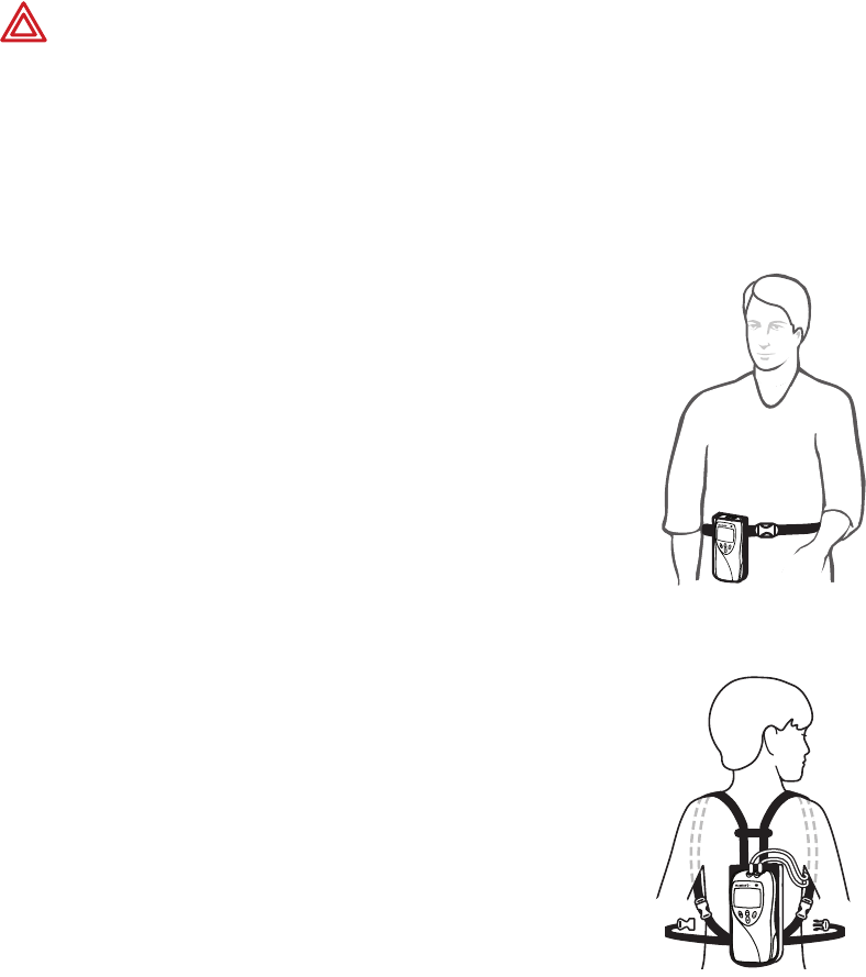
Install the carrying pouch
Adult carrying pouch
The Adult Carrying Pouch is intended for ambulatory adult
patients. It is not intended for use while the patient is in bed.
1. Put the carrying pouch on the patient and insert the monitor.
2. Carefully arrange the pouch and monitor on the patient to
avoid bruising or other skin injuries.
To maximize the monitor’s wireless transmission range,
always make sure that the monitor display is facing out and
away from the patient’s body.
Pediatric carrying pouch
The Pediatric Carrying Pouch is intended for ambulatory pediatric
patients (40 to 80 lbs., 18 to 36 kg.). It is not intended for use
while the patient is in bed.
1. Insert the monitor into the pouch.
2. Carefully arrange the pouch and the monitor on the patient to
avoid bruising or other skin injuries.
To maximize the monitor’s wireless transmission range,
always make sure that the monitor display is facing out and
away from the patient’s body.
WARNING As with all medical equipment, carefully route the patient cabling to
reduce the possibility of patient entanglement or strangulation. Use the supplied
garment clips to secure the cable properly.
WARNING When positioning the monitor pouch on the patient, make sure the
straps do not entangle the patient’s neck or cause choking. Make sure the straps
do not restrict the movement of the patient’s limbs or create a hazard when
walking or moving.

Directions for Use Chapter 2 Monitoring 29
Monitor a patient out of range of Acuity
While out of range of Acuity, the monitor continues to monitor the patient and provide
local HR/PR and SpO2 alarms or alerts at the monitor as needed.
When the patient wearing the monitor goes out of range of Acuity, do the following:
1. A DROPOUT equipment alert occurs at the Acuity Central Station. Acknowledge the
alert at Acuity.
2. An equipment alert occurs at the monitor with this message:
ACUITY CONNECTION LOST
Depending on how the monitor is configured (as controlled by Acuity), this alert can
also cause the monitor to emit audible alert tones.
If tones are enabled, the authorized person should press on the monitor to
acknowledge (dismiss) the alert and silence this instance of the alert tone.
When the patient returns within range of Acuity, the monitor automatically reconnects to
Acuity. No clinician intervention is required.
Note
The person authorized to press to acknowledge the alert may vary,
depending on the local protocol. Follow the protocol established by your
institution.
30 Chapter 2 Monitoring Welch Allyn Micropaq Monitor
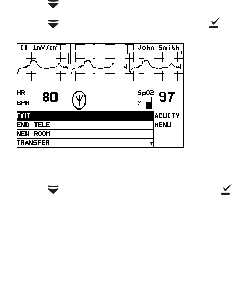
Stop monitoring a patient
If you want to discontinue monitoring the patient, follow these steps.
1. Press to display the Main Menu.
2. Press to highlight ACUITY, then press .
3. Press to highlight END TELE, then press .
4. When the monitor displays the message SAFE TO REMOVE BATTERY, remove the
battery.
If the battery is not removed within 30 seconds, the monitor will automatically try to
reconnect to the network.
5. Disconnect the leads and sensors from the patient.
Note
If you do not use END TELE to disconnect from the network as described
above, the Acuity Central Station generates a DROPOUT equipment alert at
Acuity.
If you want to monitor this same patient at a later time, you will need to reselect
the patient name from the monitor or confirm the patient ID at Acuity.
Acuity Menu

Directions for Use Chapter 2 Monitoring 31
Reconnect a recently monitored patient
1. Insert a battery into the monitor to turn on the monitor. Confirm that after a few
seconds the monitor Power-Up Screen is replaced by the initial monitoring screen.
2. The monitor will then present a series of menus and messages requesting you to
provide information about the connection and patient. The actual screens presented
depend on how long the patient has been disconnected. Provide the information as
requested. This may include:
• Select an Acuity unit.
• Select a patient from the patient list.
• Select a patient room from the room list.
• To perform ECG monitoring, see “Perform ECG monitoring” on page 21.
• To perform SpO2 monitoring, see “Perform SpO2 monitoring” on page 26.
Note
If you do not select the patient name or room while connecting the patient, you
will need to do that later at the Acuity Central Station. See “Monitor patient at
Acuity” on page 41 for more information.
32 Chapter 2 Monitoring Welch Allyn Micropaq Monitor
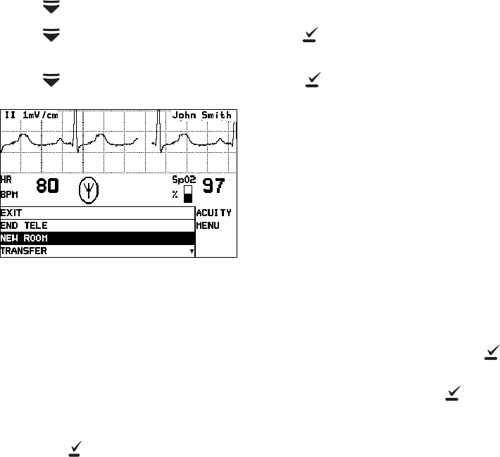
Reassign a monitored patient to a new room in the same
unit
If a patient is being monitored and you want to assign them to a new room in the same
unit, follow these steps.
1. Press to display the Main Menu.
2. Press again to highlight ACUITY and press to display the Acuity Menu
screen.
3. Press to highlight NEW ROOM, then press .
.
Within a few seconds the monitor displays a list of all available rooms, including the
patient’s current room.
• If you decide not to change the patient’s current room assignment, press (the
patient’s current room is the default selection in the list).
• To assign the patient to a new room, highlight the room and press .
• If you want to cancel the patient’s current room assignment, but do not want to
assign a new room at this time, you can highlight Select Room at Central and
press . You can then assign the room later from the Acuity Central Station, or
you can repeat this procedure and assign a new room from the monitor.
New Room Selection
Directions for Use Chapter 2 Monitoring 33
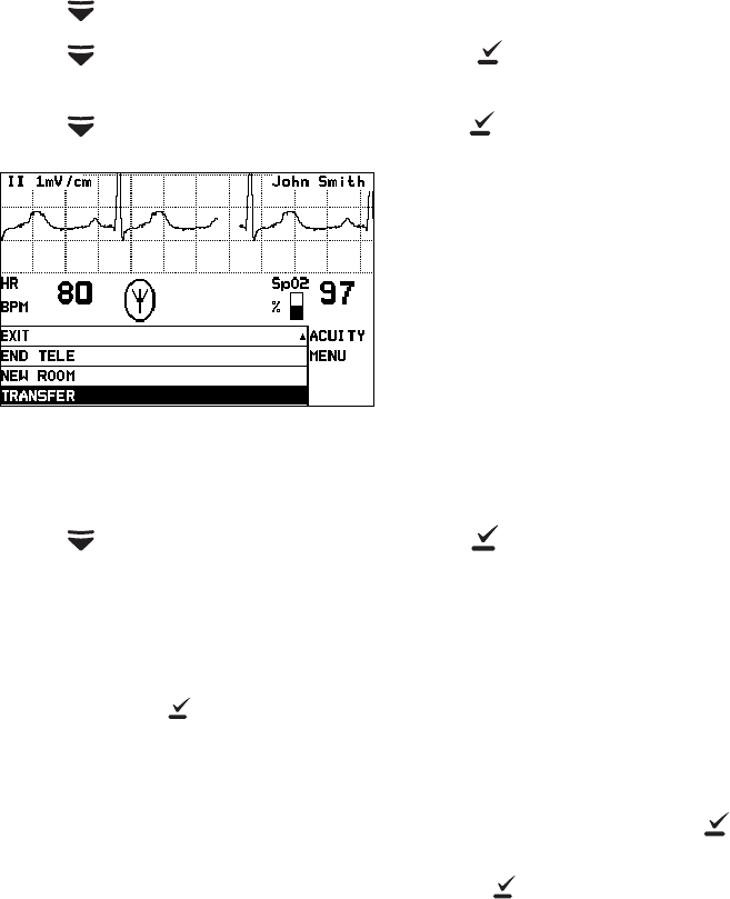
Transfer a monitored patient to a new room in a different
unit
If a patient is being monitored and you want to assign them to a new room in a different
unit, follow these steps.
1. Press to display the Main Menu.
2. Press again to highlight ACUITY and press to display the Acuity Menu
screen.
3. Press to highlight TRANSFER, then press .
Within a few seconds the monitor displays a list of units.
4. Press to highlight the new unit, then press .
The patient is not monitored at Acuity during the short time required by Acuity to
process the transfer to the new unit (typically less than one minute). However, the
patient continues to be monitored by the monitor.
(If the selected unit is currently not available, the monitor displays an appropriate
message; press to acknowledge the message and cancel the transfer.)
5. After the patient is assigned to the new unit, the monitor displays a list of unassigned
rooms. (The patient’s previous unit and room assignment is cancelled.)
• To assign the patient to a new room, highlight the room and press .
• If you decide not to assign the patient to a new room at this time, you can
highlight Select Room at Central and press . You can then assign the room
later from the Acuity Central Station, or you can assign a new room from the
monitor later using the procedure on “Reassign a monitored patient to a new
room in the same unit” on page 32.
Transfer a Patient
34 Chapter 2 Monitoring Welch Allyn Micropaq Monitor
Reassign the monitor to a new patient
If you want to discontinue monitoring a patient and reconnect the monitor to a new
patient, follow these steps.
1. Press to display the Main Menu.
2. Press again to highlight ACUITY and press to display the Acuity Menu
screen.
3. Press to highlight NEW PATIENT, then press .
The monitor then presents a series of menus and messages requesting you to
provide information about the connection and patient. The actual screens presented
depend on how the Acuity System is configured.
Provide the information as requested. This may include:
• Select an Acuity unit.
• Select a patient from the patient list. (After you select a new patient, all
monitor operating settings are reset to the Acuity System default power-up
settings.)
• Select a patient room from the room list.
If you do not select the patient name or room while connecting the patient, you will
need to do that later at the Acuity Central Station. See “Monitor patient at Acuity” on
page 41 for more information.
• To perform ECG monitoring, see “Perform ECG monitoring” on page 21.
• To perform SpO2 monitoring, see “Perform SpO2 monitoring” on page 26.
Select a New Patient