Welch Allyn X12P-2500 Telemetry Transmitter for Medical Applications User Manual 1 Cover
Mortara Instrument Inc Telemetry Transmitter for Medical Applications 1 Cover
Manual

P/N 9515-164-50-ENG
X12+
User
Manual
__________________________________________________________________________________________
CAUTION: Federal law restricts this device for sale to and use by or on the order of a physician.

®
Copyright © 2004
by Mortara Instrument, Inc.
7865 N. 86th Street
Milwaukee, Wisconsin 53224
This document contains confidential information that belongs to Mortara Instrument, Inc. No part of this document
may be transmitted, reproduced, used, or disclosed outside of the receiving organization without the express written
consent of Mortara Instrument, Inc. Mortara is a registered trademark of Mortara Instrument, Inc. Ambulatory
X12+ is a trademark of Mortara Instrument, Inc.
REF NEW
i
Technical Support and Service
Headquarters
Mortara Instrument, Inc.
7865 North 86th Street
Milwaukee, WI 53224
Tel: 414.354.1600
Tel: 800.231.7437
Fax: 414.354.4760
Internet: http://www.mortara.com
Europe Economic
Community Representative
Mortara Rangoni Europe, Srl
(European Headquarters, Italy)
Via Oradour 7
40016 S. Giorgio di Piano, BO
Tel: +39.051.6654311
Fax: +39.051.6651012
Service/Technical
Support Group
Mortara Instrument, Inc.
7865 North 86th Street
Milwaukee, WI 53224
Tel: 414.354.1600
Service: 888.MORTARA
(888.667.8272)
Fax: 414.354.4760
E-mail: techsupport@mortara.com
24 Hour Technical Support
Same Day Shipment of Replacement Parts
Biomedical Training Classes
Extended Warranties/Service Contracts
Sales Support/
Supplies & Accessories
Mortara Instrument, Inc.
7865 North 86th Street
Milwaukee, WI 53224
Tel: 414.354.1600
Fax: 414.354.4760
E-mail: sales@mortara.com
Mortara Instrument GmbH
(Germany)
Kaninenberghöhe 50
45136 Essen
Tel: +49.201.268311
Fax: +49.201.268313
Mortara Instrument B.V.
(The Netherlands)
H. Dunantplein 6
3731 CL De Bilt
Postbus 131
3720 AC Bilthoven
Tel: +31.30.2205050
Fax: +31.30.2201531
ii
Notices
Manufacturer’s Responsibility
Mortara Instrument, Inc., is responsible for the effects on safety and performance only if:
• Assembly operations, extensions, readjustments, modifications or repairs are carried out only by persons
authorized by Mortara Instrument, Inc.
• The device (Ambulatory X12+) is used in accordance with the instructions for use.
Responsibility of the Customer
The user of this product is responsible for ensuring the implementation of a satisfactory maintenance schedule.
Failure to do so may cause undue failure and possible health hazards.
Equipment Identification
Mortara Instrument, Inc. equipment is identified by a serial and reference number on the back of the device. Care
should be taken so that these numbers are not defaced.
Copyright and Trademark Notices
This document contains information that is protected by copyright. All rights are reserved. No part of this
document may be photocopied, reproduced or translated to another language without prior written consent of
Mortara Instrument, Inc.
Other Important Information
The information in this document is subject to change without notice.
Mortara Instrument, Inc. makes no warranty of any kind with regard to this material including, but not limited to,
implied warranties of merchantability and fitness for a particular purpose. Mortara Instrument, Inc. assumes no
responsibility for any errors or omissions that may appear in this document. Mortara Instrument Inc. makes no
commitment to update or to keep current the information contained in this document.
iii
Warranty Information
Your Mortara Warranty
MORTARA INSTRUMENT, INC. (hereinafter referred to as “Mortara”) hereby warrants that Mortara products
(hereinafter referred to as “Products”) shall be free from defects in material and workmanship under normal use,
service and maintenance for the warranty period of such Product from Mortara or an authorized distributor or
representative of Mortara. The warranty period is defined as twelve (12) months following the date of shipment
from Mortara. Normal use, service and maintenance means operation and maintenance in accordance with
appropriate instructions and/or information guides. This Warranty does not apply to damage to the Products caused
by any or all of the following circumstances or conditions:
a) Freight damage;
b) Parts and/or accessories of the Products not obtained from or approved by Mortara;
c) Misapplication, misuse, abuse and failure to follow the Product instruction sheets and/or information
guides;
d) Accident, a disaster affecting the Products;
e) Alterations or modifications to the Products not authorized by Mortara;
f) Other events outside of Mortara’s reasonable control or not arising under normal operating
conditions.
THE REMEDY UNDER THIS WARRANTY IS LIMITED TO THE REPAIR OR REPLACEMENT WITHOUT
CHARGE FOR LABOR OR MATERIALS, OR ANY PRODUCTS FOUND UPON EXAMINATION BY
MORTARA TO HAVE BEEN DEFECTIVE. This remedy shall be conditioned upon receipt of notice by Mortara
of any alleged defects promptly after discovery thereof within the warranty period. Mortara’s obligations under the
foregoing warranty will further be conditioned upon the assumption by the purchaser of the Products (i) of all
carrier charges with respect to any Products returned to Mortara’s principal place or any other place as specifically
designated by Mortara or an authorized distributor or representative of Mortara, and (ii) all risk of loss in transit. It
is expressly agreed that the liability of Mortara is limited and that Mortara does not function as an insurer. A
purchaser of a Product, by its acceptance and purchase thereof, acknowledges and agrees that Mortara is not liable
for loss, harm or damage due directly or indirectly to an occurrence or consequence therefrom relating to the
Products. If Mortara should be found liable to anyone under any theory (except the expressed warranty set forth
herein) for loss, harm or damage, the liability of Mortara shall be limited to the lesser of the actual loss, harm or
damage, or the original purchase price of the Product when sold.
EXCLUDED FROM THE LIMITED WARRANTY SET FORTH ABOVE ARE CONSUMABLE ITEMS SUCH
AS PAPER, BATTERIES, ELECTRODES, PATIENT CABLES, LEAD WIRES AND MAGNETIC STORAGE
MEDIUMS.
EXCEPT AS SET FORTH HEREIN WITH RESPECT TO REIMBURSEMENT OF LABOR CHARGES, A
PURCHASER’S SOLE EXCLUSIVE REMEDY AGAINST MORTARA FOR CLAIMS RELATING TO THE
PRODUCTS FOR ANY AND ALL LOSSES AND DAMAGES RESULTING FROM ANY CAUSE SHALL BE
THE REPAIR OR REPLACEMENT OF DEFECTIVE PRODUCTS TO THE EXTENT THAT THE DEFECT IS
NOTICED AND MORTARA IS NOTIFIED WITHIN THE WARRANTY PERIOD. IN NO EVENT,
INCLUDING THE CLAIM FOR NEGLIGENCE, SHALL MORTARA BE LIABLE FOR INCIDENTAL,
SPECIAL OR CONSEQUENTIAL DAMAGES, OR FOR ANY OTHER LOSS, DAMAGE OR EXPENSE OF
ANY KIND, INCLUDING LOSS OF PROFITS, WHETHER UNDER TORT, NEGLIGENCE OR STRICT
LIABILITY THEORIES OF LAW, OR OTHERWISE. THIS WARRANTY IS EXPRESSLY IN LIEU OF ANY
OTHER WARRANTIES, EXPRESS OR IMPLIED, INCLUDING, BUT NOT LIMITED TO THE IMPLIED
WARRANTY OF MERCHANTABILITY AND THE WARRANTY OF FITNESS FOR A PARTICULAR
PURPOSE.

iv
User Safety Information
Warning
Means there is the possibility of personal
injury to you or others.
Caution
Means there is the possibility of damage to
the equipment.
Note Provides information to further assist in the
use of the device.
Federal law restricts this device for sale to and use by or on the order
of a physician.
Warning
• Device (Ambulatory X12+) transmits data reflecting a patient’s physiological condition to a properly
equipped electrocardiograph and when reviewed by a trained physician or clinician can be useful in
determining a diagnosis. However, the data should not be used as a sole means for determining a patient’s
diagnosis.
• To maintain designed operator and patient safety, peripheral equipment and accessories used that can come
in direct patient contact, must be in compliance with UL 2601-1, IEC 601-1 and IEC 601-2-25.
• FCC Warning (Part 15.21): Changes or modifications not expressly approved by the party responsible for
compliance could void the user’s authority to operate the equipment.
• To maintain designed operator and patient safety, only use parts and accessories supplied with the device
and available through Mortara Instrument, Inc.
• To avoid the possibility of serious injury or death during patient defibrillation, do not come into contact
with device or patient cables. Additionally, proper placement of defibrillator paddles in relation to the
electrodes is required to minimize harm to the patient.
• A possible explosion hazard exists; do not use the device in the presence of flammable mixtures with air,
oxygen or nitrous oxide.
• Defibrillation protection is guaranteed only if the original patient cable is used.
• Simultaneous connection to other equipment may increase leakage current.
• Some stimulators may cause interference with the signal.
• ECG electrodes could cause skin irritation and should be examined daily. Reposition and change
electrodes every 24 hours, though it may be necessary to do so sooner if signs of irritation or inflammation
occur.
• Before attempting to use the device for clinical applications the operator must read and understand the
contents of the manual and any documents accompanying the device.

v
Caution(s)
• To prevent possible damage to the keypad, do not use sharp or hard objects to depress keys, only use
fingertips.
• Do not attempt to clean the device or patient cables by submersing into a liquid, autoclaving, or steam
cleaning.
• Wipe the exterior surface of the device and patient cables with a sterilizing disinfectant, and then dry with
a clean cloth.
• Conductive parts of the patient cable, electrodes and associated Type CF connections, including the neutral
conductor of the patient cable and electrode, should not come into contact with other conductive parts,
including earth ground.
• The Ambulatory X12+ and Patient Cable should be cleaned between each use.
• Do not pull or stretch patient cables as this could result in mechanical and/or electrical failures. Patient
cables should be stored after forming them into a loose loop.
• The Ambulatory X12+ will only work with electrocardiographs that are equipped with the appropriate
option.
• No user serviceable parts are inside. Any modification of this device may alter defibrillator protection.
Any modification to any part of this device is to be performed by qualified service personnel only.
• The following equipment may cause interference with the RF channel: microwave ovens, diathermy units
with LANs (spread spectrum), amateur radios and government radar.
• To prevent possible damage to the device during transport and storage (while in original packaging) the
following environmental conditions must be adhered to:
Ambient Temperature Range:
-20°C to 65°C (-4°F to 149°F)
Relative Humidity Range:
5% to 95% (non-condensing)
Atmosphere Pressure:
700 hPa to 1060 hPa
• Allow the device to stabilize within its intended operating environment for a minimum of two hours prior
to use. The allowable operating environment is as follows:
Ambient Temperature Range:
0°C to 45°C (32°F to 113°F)
Relative Humidity Range:
5% to 95% (non-condensing)
Atmosphere Pressure:
700 hPa to 1060 hPa
vi
Warning(s)
In some countries the use of the X12+ transmitter (2400 MHz version) has been limited as follows:
Spain: use is limited to channels in the range 8B to E6 (inclusive).
France: use is limited to channels in the range 8E to A5 (inclusive).
The channel setting of the X12+, when used in the above listed countries, must be set accordingly, as explained
in this manual at section 2.
FCC Compliance Statement
In the United States, use of the X12+ transmitters is regulated by Federal Communications Commission
(FCC).
FCC ID: HJR-X12-600-15
FCC ID: HJR-X12P-2500
These devices comply with Part 15 of the FCC rules.
Operation is subject to the following conditions:
1. This device may not cause harmful interference, and
2. This device must accept any interference received, including interference that may cause
undesired operation.
• The X12+ (600) must be used solely on the premises of health care facilities (see Part 15, section
15.242a).
• A health care facility operating the X12+ (600) must coordinate with the directors of existing
nearby TV stations and Radio Astronomy Observatories to ensure compatible use. Minimum
separation distances from such facilities may apply. It may be necessary to obtain written
authorization from such facilities prior to installation and use of the X12+ (Part 15, section
15.242d,e).
Industry Canada Compliance Statement
In Canada, use of the X12+ (600) transmitter is regulated by Industry Canada.
Canada ID: 3758104616
This device complies with RSS-210 of the Industry Canada rules.
This telemetry device is only permitted for installation in hospitals and health care facilities. Devices shall
not be operated in mobile vehicles (even ambulances and other vehicles associated with health care
facilities). The installer/user of this device shall ensure that it is at least 80 km from the Penticton radio
astronomy station (British Columbia latitude: 49o 19' 12" N, longitude: 118o 59'56" W). For medical
telemetry systems not meeting this 80 km separation (e.g. the Okinagan valley, British Columbia) the
installer/ user must coordinate with and obtain the written concurrence of the Director of the Penticton
radio astronomy station before the equipment can be installed or operated. The Penticton contact is
Tel: 250-493-2277/ fax: 250-493-7767.

vii
Note
• Proper patient preparation is important to proper application of ECG electrodes and operation of the
device.
• Patient cables should be checked for cracks or breakage in their exterior properties prior to use.
• As defined by IEC 601-1 and IEC 601-2-25, the device is classified as follows:
- Internally powered
- Type CF applied parts
- Ordinary equipment
- Not suitable for use in the presence of flammable mixtures with air, oxygen or nitrous oxide
- Continuous operation
• The X12+ is a UL classified device:
Medical Equipment
WITH RESPECT TO ELECTRIC SHOCK,
FIRE, AND MECHANICAL HAZARDS ONLY,
IN ACCORDANCE WITH UL 60601-1,
CAN/CSA C22.2 No. 601.1, IEC60601-1 AND
IEC60601-2-25.
5P35
Equipment Symbols
Symbol Delineation
Attention, consult accompanying
documents
Attention, consult accompanying
documents.
Compliance with Directive 1999/5/EC
Defibrillator-proof type CF input
Battery

viii
Indicates compliance to applicable EEC
Directives
Electromagnetic Compatibility (EMC)
Electromagnetic compatibility with surrounding devices should be assessed when using the
X12+ Transmitter.
An electronic device can either generate or receive electromagnetic interference. Testing for electromagnetic
compatibility (EMC) has been performed on the X12+ Transmitter according to the international standard for EMC
for medical devices (IEC 60601-1-2). This IEC standard has been adopted in Europe as the European Norm (EN
60601-1-2).
The X12+ Transmitter should not be used adjacent to, or stacked on top of other equipment. If the X12+
Transmitter must be used adjacent to or stacked on top of other equipment, verify that the X12+ Transmitter
operates in an acceptable manner in the configuration in which it will be used.
Fixed, portable, and mobile radio frequency communications equipment can affect the performance of medical
equipment. See Table X-4 for recommended separation distances between the radio equipment and the X12+
Transmitter.
Accessories and Cables Warning
The use of accessories and cables other than those specified below, may result in increased emissions or decreased
immunity of the X12+ Transmitter.
Description
Part Numbers
10-wire LeadForm Patient Cable/ Domestic
• Standard
• Large
10-wire LeadForm Patient Cable/ International
• Standard
• Large
9293-017-50
9293-026-50
9293-017-51
9293-026-51

ix
Table X-1 Guidance and Manufacturer’s Declaration: Electromagnetic Emissions
The X12+ Transmitter is intended for use in the electromagnetic environment specified in the table below. The
customer or the user of the X12+ Transmitter should assure that it is used in such an environment.
Emissions Test Compliance Electromagnetic Environment: guidance
RF Emissions
CISPR 11
Group 2
The X12+ Transmitter must emit electromagnetic energy
in order to perform its intended function. Nearby
electronic equipment may be affected.
RF Emissions
CISPR 11
Class B
Harmonic
Emissions
IEC 61000-3-2
Not Applicable
Voltage
fluctuations/
flicker emissions
IEC 61000-3-3
Not Applicable
The X12+ Transmitter is suitable for use in all
establishments, including domestic establishments and
those directly connected to the public low-voltage power
supply network that supplies buildings used for
domestic purposes.

x
Table X-2 Guidance and Manufacturer’s Declaration: Electromagnetic Immunity
The X12+ Transmitter is intended for use in the electromagnetic environment specified below. The customer or the
user of the X12+ Transmitter should assure that it is used in such an environment.
Emissions Test
Compliance
Compliance
Level
Electromagnetic Environment:
guidance
Electrostatic
Discharge (ESD)
IEC 61000-4-2
+/- 6 kV contact
+/- 8 kV air
+/- 6 kV contact
+/- 8 kV air
Floors should be wood, concrete, or
ceramic tile. If floors are covered with
synthetic material, the relative humidity
should be at least 30%.
Electrical Fast
transient/burst
IEC 61000-4-4
+/- 2 kV for
power supply line
+/- 1 kV for
input/output lines
Not Applicable
Surge
IEC 61000-4-5
+/- 1 kV
differential mode
+/- 2 kV common
mode
Not Applicable
Voltage dips,
short
interruptions and
voltage variations
on
power supply
input
lines
IEC 61000-4-11
<5% UT
(>95% dip in UT)
for 0.5 cycle
40% UT
(60% dip in UT)
for 5 cycles
Not Applicable
Power frequency
(50./60 Hz)
magnetic field
3 A/m
3 A/m
Power frequency magnetic fields should
be at levels characteristic of a typical
location in a typical commercial or
hospital environment.
Note: UT is the a.c. mains voltage prior to application of the test level.
xi
Table X-3 Guidance and Manufacturer’s Declaration: Electromagnetic Immunity
The X12+ Transmitter is intended for use in the electromagnetic environment specified below. The customer or the
user of the X12+ Transmitter should assure that it is used in such an environment.
Emissions Test IEC 60601
Test Level
Compliance
Level
Electromagnetic Environment: guidance
Conducted RF
IEC 61000-4-6
3 Vrms
150 kHz to
80 MHz
3 Vrms
150 kHz to
80 MHz
Radiated RF
IEC 61000-4-3
3 Vrms
80 MHz to
2.5 GHz
3 Vrms
80 MHz to
2.5 GHz
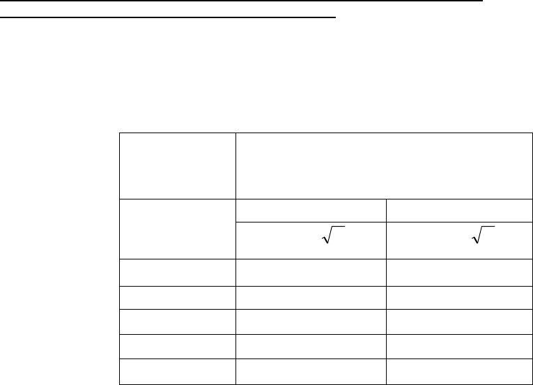
Portable and mobile RF communications
equipment should be used no closer to any part of
the X12+ Transmitter, including cables, than the
recommended separation distance calculated
from the equation applicable to the frequency of
the transmitter.
Recommended separation distance
P
Vrms
d
=
3
5.3
P
mV
d
=
/3
5.3 80 MHz to 800 MHz
P
mV
d
=
/3
7 800 MHz to 2.5 GHz
Where P is the maximum output power rating of
the transmitter in watts (W) according to the
transmitter manufacturer and d is the
recommended separation distance in meters (m).
Field strengths from fixed RF transmitters, as
determined by an electromagnetic site surveya,
should be less than the compliance level in each
frequency rangeb.
Interference may occur in the vicinity of
equipment marked with the following symbol:
a. Field strengths from fixed transmitters, such as base stations for radio (cellular/cordless) telephones and land
mobile radios, amateur radios, AM and FM radio broadcast and TV broadcast cannot be predicted theoretically with
accuracy. To assess the electromagnetic environment due to fixed RF transmitters, an electromagnetic site survey
should be considered. If the measured field strength in the location in which the X12+ Transmitter is used exceeds
the applicable RF compliance level above, the X12+ Transmitter should be observed to verify normal operation. If
abnormal performance is observed, additional measures may be necessary, such as reorienting or relocating the
X12+ Transmitter.
b. Over the frequency range 150 kHz to 80 MHz, field strengths should be less than [3] V/m.
xii
Table X-4 Recommended Separation Distances Between Portable and Mobile RF
Communications Equipment and the X12+ Transmitter.
The X12+ Transmitter is intended for use in the electromagnetic environment in which radiated RF disturbances are
controlled. The customer or the user of the X12+ Transmitter can help to prevent electromagnetic interference by
maintaining a minimum distance between portable and mobile RF communications equipment (transmitters) and the
X12+ Transmitter as recommended below, according to the maximum output power of the communications
equipment.
Rated
Maximum
Output Power of
Transmitter W
Separation Distance According to Frequency
of
Transmitter (m)
150 KHz to 800 MHz 800 MHz to 2.5 GHz
Pd 2.1= Pd 3.2=
0.01 0.1 m 0.2 m
0.1 0.4 m 0.7 m
1 1.2 m 2.3 m
10 4.0 m 7.0 m
100 12.0 m 23.0 m
For transmitters rated at a maximum output power not listed above, the recommended separation distance d in
meters (m) can be estimated using the equation applicable to the frequency of the transmitter, where P is the
maximum output power rating of the transmitter in watts (W) according to the transmitter manufacturer.
Note 1: At 800 MHz, the separation distance for the higher frequency range applies.
Note 2: These guidelines may not apply in all situations. Electromagnetic propagation is affected by the absorption
and reflection from structures, objects, and people.

xiii
Table of Contents
1 Introduction
Manual Purpose ..............................................................................................................................................1-1
Audience..........................................................................................................................................................1-1
System Description..........................................................................................................................................1-1
Equipment Included.........................................................................................................................................1-1
X12+ Front View ..............................................................................................................................................1-2
LeadForm Patient Cable..................................................................................................................................1-2
X12+ Transmitter in Carrying Pouch ...............................................................................................................1-3
X12+ Ambulatory Transmitter Part Numbers ..................................................................................................1-4
Supplies Contact .............................................................................................................................................1-4
Ambulatory X12+ Specifications......................................................................................................................1-5
Operation
2
Read Instructions ............................................................................................................................................2-1
Battery Installation/Removal/Battery Door .....................................................................................................2-2
Turning the Ambulatory X12+ ON ..................................................................................................................2-3
Turning the Ambulatory X12+ OFF ................................................................................................................2-3
LCD Display Battery Voltage Indicator ...........................................................................................................2-3
Attaching the Patient Cable ............................................................................................................................2-4
Patient Hook-Up .............................................................................................................................................2-4
Skin Preparation ................................................................................................................................2-4
Positioning the Electrodes .................................................................................................................2-5
Using the Keypad ...........................................................................................................................................2-6
Main Menu ......................................................................................................................................................2-6
Top Level Menu Options ................................................................................................................................2-7
Lead Check ....................................................................................................................................................2-8
Checking Impedances ....................................................................................................................................2-8
Displaying ECG Leads ...................................................................................................................................2-9
Configuring the Ambulatory X12+ Transmitter ...............................................................................................2-9
Setting the Transmission Channel Number ......................................................................................2-11
Setting the Number of Patient Cable Leadwires ...............................................................................2-11
Setting Language ..............................................................................................................................2-12
Viewing Software Version Number ....................................................................................................2-12
Viewing Battery Voltage ....................................................................................................................2-12
Starting a Patient Transmission Session ........................................................................................................2-12
Sending (Optional) Call Signals .....................................................................................................................2-13
Ending a Transmission Session .....................................................................................................................2-13
3 Maintenance
Cleaning the Ambulatory X12+ Transmitter and Patient Cable ......................................................................3-1
Periodic Maintenance ......................................................................................................................................3-1
Disposal of Waste Material..............................................................................................................................3-1

xiv
Appendix Messages and Information
A
Table of Messages ..........................................................................................................................................A-1
System Information Log...................................................................................................................................A-2
Serial Number and Part Number Location ......................................................................................................A-3
Appendix Channel Assignments
B
600MHz ...........................................................................................................................................................B-1
2500MHz .........................................................................................................................................................B-2
Appendix Translations
C
Table of Translations .......................................................................................................................................C-1
Glossary ..................................................................................................................................................G-1
Index ...........................................................................................................................................................I-1

_____________________________________________________________________Section 1
1-1
1 Introduction
X12+ Overview
Manual Purpose
The X12+ User Manual explains how to operate the Ambulatory X12+ Transmitter. It shows how to
• Acquire and transmit 12-Lead ECG signals to a receiving device
• Setup device configurations
Audience
This manual is written for clinical professionals who are expected to have a working knowledge of medical
procedures and terminology as required for monitoring cardiac patients.
Conventions
Keys, such as Enter, appear in bold Arial font.
Text on the LCD screen of the X12+ appears in regular Arial font.
System Description
The Mortara Instrument Ambulatory X12+ Telemetry Module represents the state-of-the-art in Wireless
Electrocardiographic Technology. It provides a means to acquire and transmit 12-lead cardiac signals without
direct connections to an electrocardiograph. Design innovations implemented in the X12+ Telemetry Module
achieve real-time acquisition, RF transmission of simultaneous 12-lead ECG data with diagnostic quality to the
Mortara Receiver Module while allowing the patient to be ambulatory.
In addition, by using a very high monitoring frequency to transmit cardiac signals, the diagnostic bandwidth of
the signals is maintained.
The Ambulatory X12+ affords the patient complete freedom of movement. Unlimited range can also be
obtained with addition of the Mortara Antenna Network Box(s).
The X12+ Transmitter uses a single AA alkaline battery.
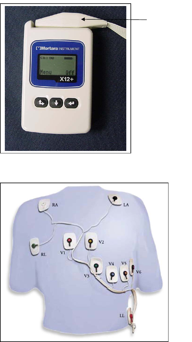
Equipment Included
The following equipment is necessary to use the Ambulatory X12+ Telemetry Module:
• Ambulatory X12+ (transmitter),
• One AA battery, 1.5V,
• Mortara Receiver Module with Antennas,
• Patient cable
• Antenna Network (optional)
X12+_________________________________________________________________________
1-2
X12+ Transmitter with Patient Cable
Front View, Figure 1-1
LeadForm Patient Cable, Figure 1-2
Patient Cable
_____________________________________________________________________Section 1
1-3
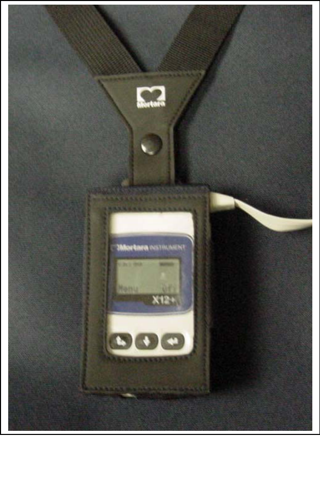
X12+ Transmitter in Carrying Pouch, Figure 1-3
Carrying Pouch
with Neck Strap

X12+_________________________________________________________________________
1-4
Mortara Part Numbers/ X12+ Ambulatory Transmitter
X12+ Transmitter
Description
Part Numbers
X12+ Transmitter
X12+ Battery Door
X12+ Carrying Pouch with Belt and Neck Strap
10-wire LeadForm Patient Cable/ Domestic
• Standard
• Large
10-wire LeadForm Patient Cable/ International
• Standard
• Large
X12+ User Manual / English
X12+ Short Form Instruction Card / English
Monitoring Hook-up Kit
• 10 Monitoring Electrodes
• 1 Abrasive Pad
• 1 4x4 Gauze wipe
• 1 Razor
• 2 Alcohol Prep Pads
X12PLUS-XXX-XXXXX
8346-003-50
8485-020-50
9293-017-50
9293-026-50
9293-017-51
9293-026-51
9515-164-50-ENG
NEW
9294-009-50
To order additional supplies, contact a Mortara Instrument customer service representative at:
Mortara Instrument, Inc.
7865 N. 86th Street
Milwaukee, WI 53224
Phone: 1-888-MORTARA (667-8272)
Fax: (414) 354-4760
Internet: http://www.mortara.com

____________________________________________________________________________Section 1
1-5
Mortara Specifications/ X12+ Ambulatory Transmitter
X12+ Ambulatory Transmitter
FEATURE Specifications
INTRUMENT TYPE
12-Lead ECG Transmitter
INPUT CHANNELS
Continuous 12-lead signal
acquisition and transmission
STANDARD LEADS TRANSMITTED I, II, III, aVR, aVL, aVF, V1, V2, V3,
V4, V5 and V6
FREQUENCY RANGE*
608.48 MHz to 631.52 MHz or
2400.96 MHz to 2482.56 MHz
SPECIAL FUNCTIONS
Lead Impedance Check, ECG
Display, Lead Fail, Low Battery
Notification, multi-purpose Call, 10-
wire, 5-wire and 4-wire options
DEFIBRILLATOR PROTECTION
In compliance with AAMI standards
and IEC 601-2-25
NUMBER OF CHANNELS
256, User Selectable
FUNCTION KEYS
Up/Right, Down and Enter keys for
ON, menu navigation and CALL
DEVICE CLASSIFICATION
Type CF, battery-operated
WEIGHT
4 Ounces (125 g) without battery
DIMENSIONS
2.5 x 3.5 x .98 inches
(64 x 91 x 25 mm)
BATTERY
1 AA Alkaline, 30 hour typical life
Notes: Manufacturer does not supply accessories for direct Cardiac Applications.
*Operating frequency range is dependent on the X12+ part number.
Operating range performance is 15 meters with no barriers.
X12+_______________________________________________________________________________
1-6

____________________________________________________________________________Section 2
2-1
Operation
2
Please Read Instructions before Operating this Device
The user of this device is cautioned that any changes or modifications not expressly approved by
Mortara Instrument, Inc., could void the user’s authority to operate the equipment.
This device complies with part 15 of the FCC rules. Operation is subject to the following conditions:
1. This device may not cause harmful interference, and
2. This device must accept any interference received, including interference that may cause
undesired operation.
• The X12+ (600) must be used solely on the premises of health care facilities (see Part 15, section
15.242a).
• A health care facility operating the X12+ (600) must coordinate with the directors of existing
nearby TV stations and Radio Astronomy Observatories to ensure compatible use. Minimum
separation distances from such facilities may apply. It may be necessary to obtain written
authorization from such facilities prior to installation and use of the X12+ (Part 15, section
15.242d,e).
Operating frequencies are 608.48-631.52 MHz or 2400.96-2452.96 MHz operating frequency range.
FCC ID: HJR-X12-600-15
FCC ID: HJR-X12P-2500
This device is defibrillator-protected in compliance with AAMI standards and IEC 601-2-25.
X12+_______________________________________________________________________________
2-2
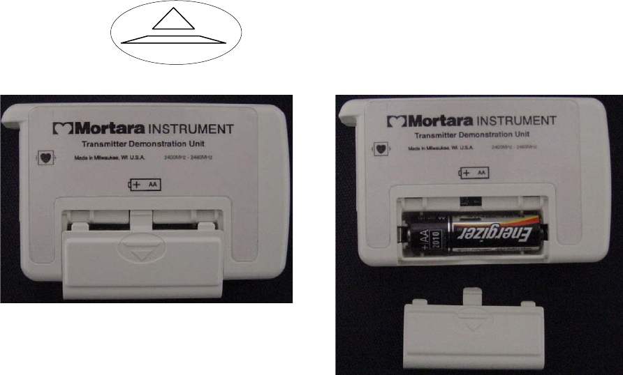
Battery Installation / Removal and Opening / Closing the Battery Door
The battery compartment is accessible via the battery door of the Ambulatory X12+ Transmitter.
1) Position the X12+ Transmitter with its back facing you to open the battery door.
2) Press down on the battery door arrow symbol and slide the battery door out.
3) Insert one AA alkaline battery into the battery compartment. Align the positive (+) and negative (-)
indicators of the battery with the designators in the battery compartment.
4) To close the battery door, place the battery door on the X12+ as shown above and slide the door in until it
snaps into place.
Notes: AA alkaline batteries are recommended.
The typical life of one AA alkaline battery is 30 hours.

____________________________________________________________________________Section 2
2-3
Turning the Ambulatory X12+ ON
The X12+ will power up as soon as a battery with a minimum of 1.0 Volts has been inserted into the battery
compartment. If the X12+ was turned off after its last use, the user has two options to power the X12+ ON:
1) Remove and re-insert the AA alkaline battery, or
2) Press the Up/Right arrow key on the front of the X12+ Transmitter
The X12+ will power up and display the Main LCD Menu within three seconds.
Turning the Ambulatory X12+ OFF
When the Ambulatory X12+ is not in use, the user has two options to power the X12+ transmitter OFF:
1) Remove the battery, or
2) Press and hold the Enter key on the front of the X12+ Transmitter for a period of three seconds
a) A prompt will appear in the LCD display
b) Press the Up/Right arrow key to highlight YES; or skip this step if NO is desired
c) Press the Enter key to select
LCD Display Battery Voltage Indicator
The X12+ Transmitter is powered with a single AA alkaline battery that requires a minimum of 1.0 Volts to operate.
When the battery contains sufficient voltage the X12+ LCD Main Menu will display a picture representing the
current battery voltage in increments of 100%, 75%, 50% and 25%. If a battery with unknown voltage is inserted
and the LCD menu does not appear, insert a new battery.
100% 75% 50% 25%
An option to display the actual battery voltage is also available in the Config menu and will be explained later in
this chapter.
Note: In the event that the battery voltage is below 1.0 Volts, the X12+ transmitter will not power on.
Insert a new AA alkaline battery to continue operation.
When the battery indicator shows a voltage of 25%, the battery should be discarded and a new battery
should be inserted into the battery compartment.
X12+_______________________________________________________________________________
2-4
Attaching the Patient Cable
The LeadForm Patient Cable consists of a connector block, main cable and leadwires connected to the main cable.
Each leadwire terminates in a snap connector. The leadwires are positioned on the main cable to follow the contour
of the torso.
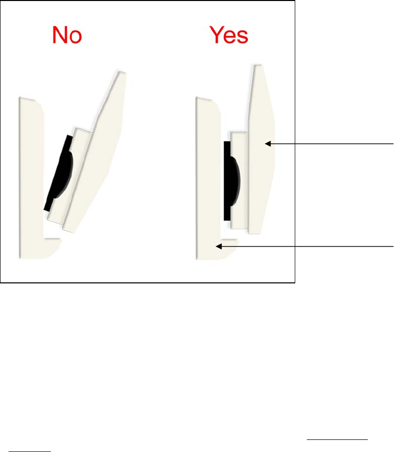
Insert the connector block into the input connector on the top of the X12+ Transmitter.
Note: Be careful to insert the connector block parallel to the input connector of the X12+.
Patient Hook-Up
Skin Preparation
Skin preparation is important to perform before electrode attachment to help insure good signal quality when
transmitting patient data. Poor skin-electrode contact may cause noise or artifact which can affect the analysis of the
ECG data. Low amplitude signals may also be the result of poor skin-electrode contact.
To prepare the skin
1. Identify the electrode sites on the torso by referring to the next section on Positioning the
Electrodes.
2. Remove any hair from the electrode sites using a razor.
3. Wipe oils from the electrode sites with an alcohol prep pad.
4. Remove any dead skin from the electrode sites with an abrasive pad. Two to three moderate rubs
at each site should be sufficient.
Connector Block
Input Connector
____________________________________________________________________________Section 2
2-5
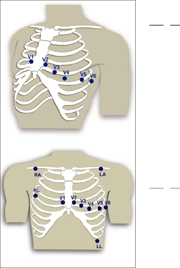
Positioning the Electrodes
Lateral View, Precordial Electrode Placement (top)
Front View, Limb and Precordial Electrode Placement (bottom)
When the electrode sites have been identified and prepped, remove the clear electrode covering and apply an
electrode to each of the (10) sites. Secure each electrode by exerting slight pressure around the outer edge and inner
ring of the electrode.
To connect the leadwires, begin with connecting the LL leadwire (Red – labeled LL) to the LL electrode. Connect
the next leadwire on the cable (Fuchsia – labeled V6) to the V6 electrode. Continue connecting the snap connectors
to the electrodes as positioned on the main cable.
Note: QRS morphology may be slightly different from the standard 12-Lead ECG due to modification of limb
electrode placement.
Precordial Electrodes
AAMI IEC
V1 C1 Fourth intercostal space at
the right sternal border
V2 C2 Fourth intercostal space at
the left sternal border
V3 C3 Midway between V2 and
V4
V4 C4 Fifth intercostal space at
the left of the midclavicular
line
V5 C5 Anterior axillary line on the
same horizontal level as V4
V6 C6 Mid-axillary line on the
same horizontal level as V4
and V5
Limb Electrodes
AAMI IEC
RA R Right clavicle as shown
LA L Left clavicle as shown
RL N Reference or ground lead,
should be placed to
maximize patient comfort
LL F Lower left side of body, as
close to the hip as possible
X12+_______________________________________________________________________________
2-6
Using the Keypad
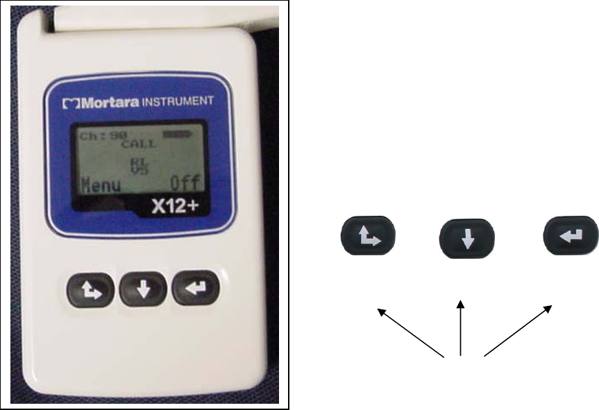
The keypad is located on the front, lower portion of the Ambulatory X12+ Transmitter. Three keys are available for
navigating through the LCD Menu screens, for powering the X12+ ON/OFF and for sending calls during
transmission.
These include the Up/Right, Down and Enter keys.
Main Menu
The X12+ Transmitter Main LCD menu displays the following information.
• CH: XX = Transmission Channel
• BATTERY SYMBOL = 100%, 75%, 50% or 25% Battery Charge
• Menu = label over the Up/Right key for access to Menu Options
• Off = label over the Enter key to power the X12+ Off
• RL, RA, LL, RL, V1, V2, V3, V4, V5 and/or V6 = Leads in Fail
• CALL = a Call signal has been transmitted
To send a CALL signal, press any one of the three keypad keys. A CALL indicator will appear on the LCD display
to notify the user that a call signal has been transmitted.
To turn the X12+ transmitter off, press and hold the Enter key for approximately three seconds. A menu will
appear prompting the user to select YES or NO. If a selection is not made within three seconds the prompt menu
will be replaced by the Main Menu.
Up/Right Down Enter
CALL = Any Key
Menu Off

____________________________________________________________________________Section 2
2-7
Top Level Menu Options
To select Menu options, press and hold the Up/Right arrow key for approximately three seconds. Use the
Up/Right and Down arrow keys to scroll and the Enter key to select. The top level menu includes the following
options.
• LEAD CHECK
• DISPLAY ECG
• CONFIGURE
• DONE
An operational flowchart of Menu options depicts the flow of functionality using the Up/Right, Down and Enter
keys.
Operational Flow Chart
MAIN Display
CH: 80 Battery
Lead Fail
Indication
Menu Off
LEAD CHECK
DISPLAY ECG
CONFIGURE
DONE
Return to Main Display
CHANNEL
Select between 256
channels
CABLE
Select between:
10-Leadwire
5-Leadwire
4-Leadiwre
VERSION
Software version and
transmission frequency
VERSION 1.00
ISM 2400
DONE
Return to Configure
Menu
LANGUAGE
Select Language:
English / Italian /
German / French…
BATTERY
Display real time
Battery Voltage
X12+_______________________________________________________________________________
2-8
Lead Check
The LEAD CHECK, DISPLAY ECG and CONFIGURE tasks are performed prior to starting a new patient.
LEAD CHECK, DISPLAY ECG and DONE are typically selected prior to each new session.
Checking Impedances
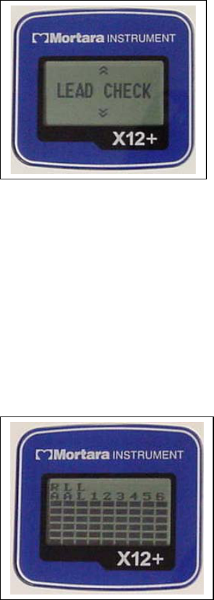
LEAD CHECK is the first option displayed on the LCD screen after patient hook-up and is a valuable tool for
verifying and optimizing signal quality before starting a patient session.
From the Main menu, scroll to LEAD CHECK using the Down or Up key. Press the Enter key to select this
option.
A graph depicting the impedance measured at the Right Arm (RA), Left Arm (LA), Left Leg (LL) and V1 through
V6 electrodes is displayed from left to right in vertical columns on the screen. The higher the bar, the better the
contact is between the skin and the electrode.
A full-bar graph (6 bars) means optimal high quality and good electrode contact. For good quality transmissions,
the bars should be at least 4 bars high. A low-bar graph means poor quality and high electrode impedance. The skin
preparation should be checked for improvement and, if necessary, the electrode(s) should be replaced.
Once acceptable impedance levels are verified, press any of the three keys to return to the Top Level Options Menu.
____________________________________________________________________________Section 2
2-9
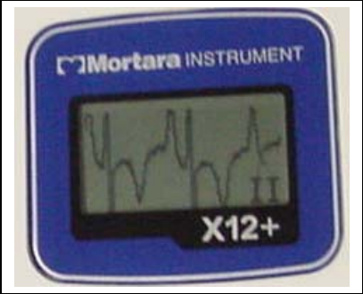
Displaying ECG Leads
DISPLAY ECG is used to visually inspect leads I, II, III, V1, V2, V3, V4, V5 and V6 before starting a transmission
session. Check the signal quality and lead amplitude for each lead.
From the Main menu, scroll to ECG Preview using the Down or Up/Right keys. Press the Enter key to select
this option.
Lead I is the first lead displayed on the screen. Use the Down or Up/Right key to scroll from lead to lead.
After visual verification of all leads, press the Enter key to return to the Top Level Menu Options.
Use the Down or Up/Right keys to scroll to Exit and select the Enter key to return to the main menu.
Configuring the Ambulatory X12+ Transmitter
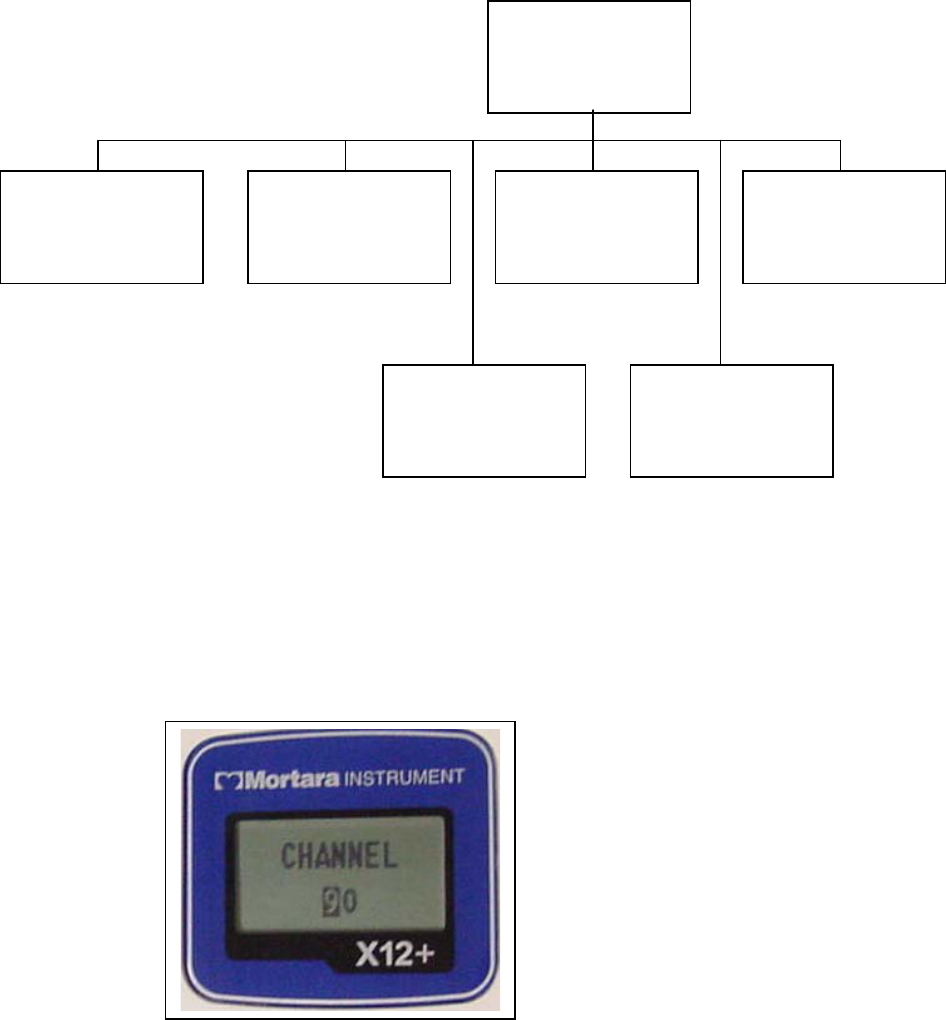
CONFIGURE is used to set the transmitter channel number, the number of patient cable lead wires and language
defaults. This menu is also used to display the software version number and current battery voltage. These settings
are typically set before the initial patient session on the X12+ and do not need to be set on a per patient basis.
From the Main menu, scroll to CONFIGURE using the Down or Up/Right key. Press the Enter key to select this
option.
The CONFIGURE menu includes the following options.
• CHANNEL
• CABLE
• LANGUAGE
• VERSION
• BATTERY
• DONE
Use the Down or Up/Right key to scroll through the CONFIGURE menu options. Press the Enter key when the
desired option is displayed. Select DONE and press the Enter key to return to the Top Level Menu Options. Scroll
to DONE and press the Enter key to return to the main menu.
On the next page, an operational flowchart of CONFIGURE menu options depicts the flow of functionality via the
Up/Right, Down and Enter keys.
X12+_______________________________________________________________________________
2-10
CONFIGURE Operational Flow Chart
Setting the Transmission Channel Number
The X12+ transmits the patient’s cardiac signals to the electrocardiograph using a specific channel number.
CHANNEL is used to enter the optimal transmission channel number before starting a patient session. The user
may choose from any of 256 channels. If ECG signal loss occurs, the transmission channel can be changed.
From the Main menu, scroll to CHANNEL using the Down or Up/Right keys. Press the Enter key to select this
menu option.
To enter the channel number, the cursor is moved to the right or left alphanumeric character field by pressing the
Up/Right arrow key.
To move the cursor one letter or digit at a time, press the Down arrow key. When the cursor reaches the end of the
characters, the cursor wraps to the beginning of the characters.
When finished, press the Enter key to Exit the Channel menu.
Note: When entering the Channel number, the Down arrow key is used to change the characters. The cursor
cannot be moved in the Up direction.
CONFIGURE
CHANNEL
Select between 256
channels
CABLE
Select between:
10-Leadwire
5-Leadwire
4-Leadiwre
VERSION
Software version and
transmission frequency
VERSION 1.00
ISM 2400
DONE
Return to Configure
Menu
LANGUAGE
Select Language:
English / Italian /
German / French…
BATTERY
Display real time
Battery Voltage
____________________________________________________________________________Section 2
2-11
Setting the Number of Patient Cable Leadwires
CABLE is used to set the number of leadwires for the patient cable.
From the CONFIGURE menu, scroll to CABLE using the Down or Up/Right keys. Press the Enter key to select
this option. The CABLE menu includes the following options.
• 4-Leadwire
• 5-Leadwire
• 10-Leadwire
Use the Down or Up/Right key to scroll to the desired option and press the Enter key.
When finished, press the Enter key to Exit the Cable menu
Note: When a 4-wire or 5-wire cable is selected, only the limb leads (and a V label with the 5-wire cable) will
appear in LEAD CHECK, DISPLAY ECG and lead fail messages.
Setting Language
LANGUAGE is used to select a language to view in the Main menu and all sub-menu options.
From the CONFIGURE menu, scroll to LANGUAGE using the Down or Up/Right keys. Scroll through the
language options using the Down or Up/Right keys. Press the Enter key to select the desired language.
When finished, press the Enter key to Exit the Language menu
Viewing Software Version Number
Version displays the current software version installed in the X12+ Transmitter.
From the CONFIGURE menu, scroll to VERSION using the Down or Up/Right keys. Press the Enter key to
select VERSION and view the current software.
When finished, press the Enter key to Exit the VERSION menu.
Viewing Battery Voltage
BATTERY displays the voltage of the battery currently installed in the X12+ Transmitter.
From the CONFIGURE menu, scroll to BATTERY using the Down or Up/Right keys. Press the Enter key to
select BATTERY and view the current battery voltage.
When finished, press the Enter key to Exit the BATTERY menu.
X12+_______________________________________________________________________________
2-12
Starting a Patient Transmission Session
1. Hook-up the patient.
2. Ensure that there is an AA alkaline battery in the battery compartment (see note below).
3. Press the Up/Right arrow key to turn on the X12+ Transmitter (if not already powered ON by
insertion of the battery).
4. Verify the quality of the hook-up by checking the electrode to skin impedances. Press the Up/Right
key for approximately three seconds to open the Top Level Menu options. Press the Enter key to
select LEAD CHECK. When finished, press any key to exit the LEAD CHECK menu.
5. Verify the amplitude and signal quality by displaying each of the ECG leads. Use the Up/Right and
Down keys to scroll through the top level menu options until DISPLAY ECG is displayed. Press the
Enter key to select DISPLAY ECG. Press the Up/Right key to scroll through all leads for quality
verification and then select DONE using the Enter key to return to the top level menu options.
6. Select the Up/Right and Down keys to scroll through the Top Level Menu until DONE is displayed.
Press the Enter key to select DONE and return to the Main Menu.
Note: In the event that the battery voltage is below 1.0 Volts, the X12+ transmitter will not power on.
Insert a new AA Alkaline battery to continue operation.
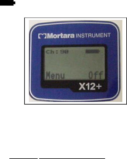
During normal operation, the following information is displayed in the LCD continuously. The Ch: xx (Channel
Number) and (battery indicator) display the transmission channel and current battery power range.
If the battery is removed during a transmission session, the X12+ stops transmitting. A battery must be inserted to
continue operation.
Notes: In the event of a lead fail condition occurring during operation, the appropriate lead fail indicator(s) is
displayed in the center of the LCD display.
Refer to Appendix A Messages and Information for information on lead fail messages.
____________________________________________________________________________Section 2
2-13
Sending (Optional) Call Signals
During the patient data transmission session, the patient may be instructed to transmit call signals from the X12+ to
a receiving device for monitoring purposes.
To send a call signal, press any one of the three keys on the X12+. The CALL message is displayed in the Main
Menu on the LCD display to inform the user that a call was sent.
Ending a Transmission Session
At the end of the patient session, the X12+ Transmitter can be turned off by:
1. Opening the battery door and removing the battery, or
2. Pressing and holding the Enter key for approximately three seconds
a. Select the Up/Right arrow key to highlight YES
b. Press the Enter key to Select YES
X12+_______________________________________________________________________________
2-14

____________________________________________________________________________________ Section 3
3-1
Maintenance
3
Cleaning the Ambulatory X12+ and Patient Cable
Turn off the Ambulatory X12+, and clean the outside with a damp cloth. Dry the equipment completely before
use.
WARNING: The Ambulatory X12+ is not water-proof. Prevent liquid from penetrating, and avoid
submerging the Ambulatory X12+ in any liquid. Sterilization is not allowed.
Periodic Maintenance
Check the Ambulatory X12+ and patient cable everyday to be sure they are not damaged or broken.
Disposal of Waste Materials
The Ambulatory X12+ needs one alkaline battery and disposable monitoring electrodes. Their disposal must be
in accordance with the following procedures:
Battery: chemical waste
Electrodes: normal waste
X12+ _______________________________________________________________________________
3-2
__________________________________________________________________________Appendix A
A-1
Appendix M essages and Information
A
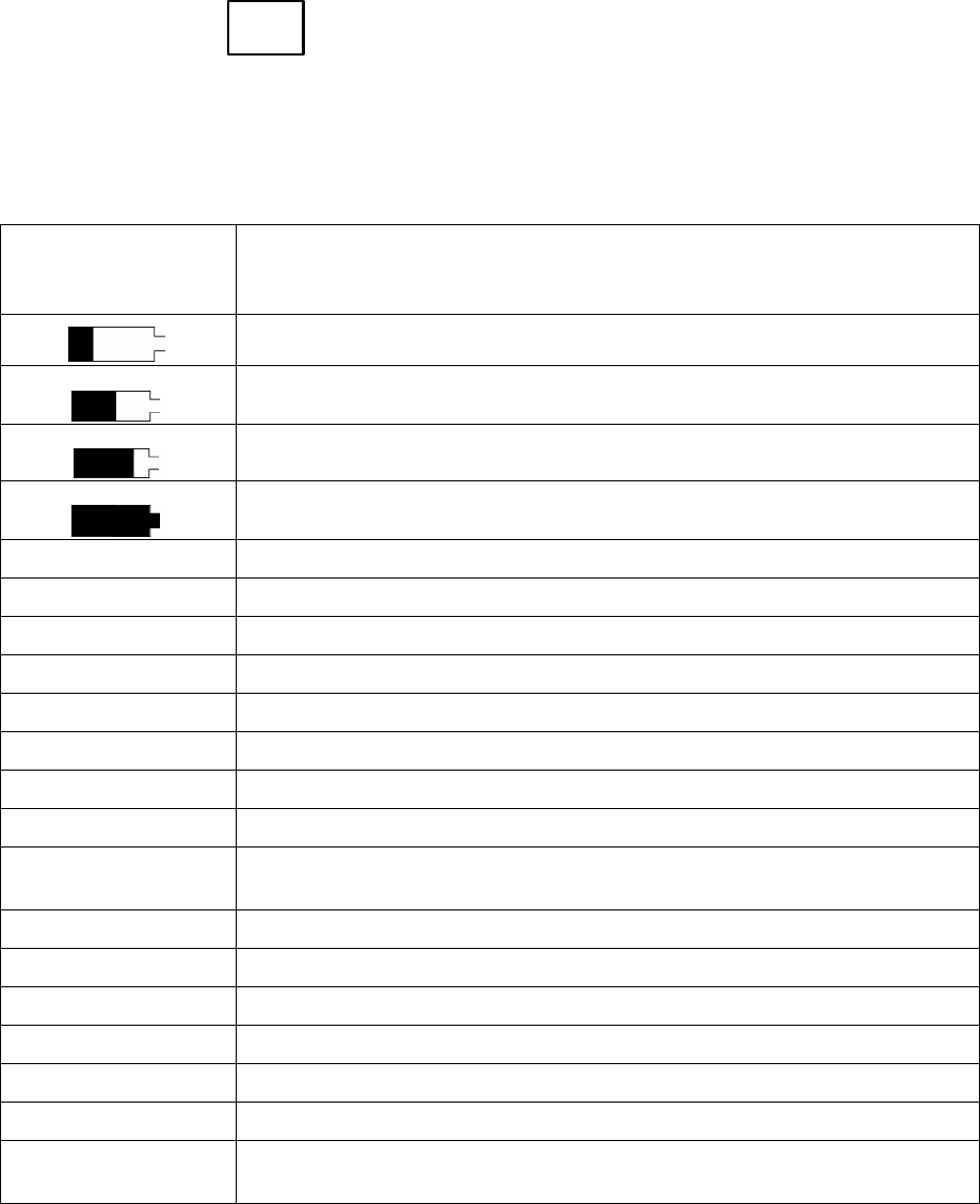
The following table describes messages that are displayed on the X12+ during patient hook-up and Transmission.
Table of Messages
Message
Solution
Battery power is low. Replace existing battery with a fully charged battery.
Battery power is at 50%.
Battery power is at 75%.
Battery power is at 100% (fully charged).
CALL A Call signal has been transmitted.
CH:XX The transmission channel that has been set for this unit.
Menu Label over the Up/Right arrow key that indicates access to Menu options
Off Label over the Enter key that indicates powering the unit off.
‘RA’ RA fail. Check if the lead wire is off or the electrode needs to be replaced.
‘RL’ RL fail. Check if the lead wire is off or the electrode needs to be replaced.
‘LA’ LA fail. Check if the lead wire is off or the electrode needs to be replaced.
‘LL’ LL fail. Check if the lead wire is off or the electrode needs to be replaced.
A combination of
‘RA/…/LL’
More than one limb lead fail or all leads fail. Check the lead wires and
electrodes.
‘V1’ V1 fail. Check if the lead wire is off or the electrode needs to be replaced.
‘V2’ V2 fail. Check if the lead wire is off or the electrode needs to be replaced.
‘V3’ V3 fail. Check if the lead wire is off or the electrode needs to be replaced.
‘V4’ V4 fail. Check if the lead wire is off or the electrode needs to be replaced.
‘V5’ V5 fail. Check if the lead wire is off or the electrode needs to be replaced.
‘V6’ V6 fail. Check if the lead wire is off or the electrode needs to be replaced.
A combination of
‘V1/…/V6’
More than one chest lead fail. Check the lead wires and electrodes.
X12+_______________________________________________________________________________
A-2
The following system information log is provided for your convenience. You need this information to set up
your system if it needs servicing. Be sure to update the information log when you add options or your system
has been serviced.
Record the model and serial number of all components, dates of removal, and/or replacement of components,
and the name of the vendor from whom the component was purchased and/or installed.
In addition to having records of this information, the system information provides a warranty record of when
your system was placed in service.
System Information Log
Manufacturer:
Mortara Instrument, Inc.
7865 N. 86th St.
Milwaukee, WI 53224
Telephone Numbers:
Domestic: 800-231-7437
European: +39-51-6650-701
Sales Department: 800-231-7437
Service Department: 888-MORTARA
Product Information:
Name of Unit/Product:
____________________
Date of Purchase: ___/___/_____
Purchased Unit From:
____________________
Serial Number: _______________
Software Version: _____________
__________________________________________________________________________Appendix A
A-3
System Information Log
For questions and service
information, when calling have serial
number and part number available.
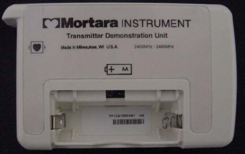
The Serial Number and Part Number (REF)
are found under the battery, in the battery
compartment on the backside of the unit
similar to the one pictured below.
Figure A-a Serial Number (SN) and Part Number (REF) Location
Notes:
X12+_______________________________________________________________________________
A-4

__________________________________________________________________________Appendix B
B-1
Appendix Channel Assignments
B
X12+-600 Channel Assignments (FCC Part 15 Compliant) Includes reference to UHF TV channel
occupying the same frequency range.
TV37 TV38 TV39 TV40
CH# MHz CH# MHz CH# MHz CH# MHz
00 608.48 40 614.48 80 620.48 C0 626.48
01 608.56 41 614.56 81 620.56 C1 626.56
02 608.64 42 614.64 82 620.64 C2 626.64
03 608.72 43 614.72 83 620.72 C3 626.72
04 608.8 44 614.8 84 620.8 C4 626.8
05 608.88 45 614.88 85 620.88 C5 626.88
06 608.96 46 614.96 86 620.96 C6 626.96
07 609.04 47 615.04 87 621.04 C7 627.04
08 609.12 48 615.12 88 621.12 C8 627.12
09 609.2 49 615.2 89 621.2 C9 627.2
0A 609.28 4A 615.28 8A 621.28 CA 627.28
0B 609.36 4B 615.36 8B 621.36 CB 627.36
0C 609.44 4C 615.44 8C 621.44 CC 627.44
0D 609.52 4D 615.52 8D 621.52 CD 627.52
0E 609.6 4E 615.6 8E 621.6 CE 627.6
0F 609.68 4F 615.68 8F 621.68 CF 627.68
10 609.76 50 615.76 90 621.76 D0 627.76
11 609.84 51 615.84 91 621.84 D1 627.84
12 609.92 52 615.92 92 621.92 D2 627.92
13 610 53 616 93 622 D3 628
14 610.08 54 616.08 94 622.08 D4 628.08
15 610.16 55 616.16 95 622.16 D5 628.16
16 610.24 56 616.24 96 622.24 D6 628.24
17 610.32 57 616.32 97 622.32 D7 628.32
18 610.4 58 616.4 98 622.4 D8 628.4
19 610.48 59 616.48 99 622.48 D9 628.48
1A 610.56 5A 616.56 9A 622.56 DA 628.56
1B 610.64 5B 616.64 9B 622.64 DB 628.64
1C 610.72 5C 616.72 9C 622.72 DC 628.72
1D 610.8 5D 616.8 9D 622.8 DD 628.8
1E 610.88 5E 616.88 9E 622.88 DE 628.88
1F 610.96 5F 616.96 9F 622.96 DF 628.96
20 611.04 60 617.04 A0 623.04 E0 629.04
21 611.12 61 617.12 A1 623.12 E1 629.12
22 611.2 62 617.2 A2 623.2 E2 629.2
23 611.28 63 617.28 A3 623.28 E3 629.28
24 611.36 64 617.36 A4 623.36 E4 629.36
25 611.44 65 617.44 A5 623.44 E5 629.44
26 611.52 66 617.52 A6 623.52 E6 629.52
27 611.6 67 617.6 A7 623.6 E7 629.6
28 611.68 68 617.68 A8 623.68 E8 629.68
29 611.76 69 617.76 A9 623.76 E9 629.76
2A 611.84 6A 617.84 AA 623.84 EA 629.84
2B 611.92 6B 617.92 AB 623.92 EB 629.92
2C 612 6C 618 AC 624 EC 630
2D 612.08 6D 618.08 AD 624.08 ED 630.08
2E 612.16 6E 618.16 AE 624.16 EE 630.16
2F 612.24 6F 618.24 AF 624.24 EF 630.24
30 612.32 70 618.32 B0 624.32 F0 630.32
31 612.4 71 618.4 B1 624.4 F1 630.4
32 612.48 72 618.48 B2 624.48 F2 630.48
33 612.56 73 618.56 B3 624.56 F3 630.56
34 612.64 74 618.64 B4 624.64 F4 630.64
35 612.72 75 618.72 B5 624.72 F5 630.72
36 612.8 76 618.8 B6 624.8 F6 630.8
37 612.88 77 618.88 B7 624.88 F7 630.88
38 612.96 78 618.96 B8 624.96 F8 630.96
39 613.04 79 619.04 B9 625.04 F9 631.04
3A 613.12 7A 619.12 BA 625.12 FA 631.12
3B 613.2 7B 619.2 BB 625.2 FB 631.2
3C 613.28 7C 619.28 BC 625.28 FC 631.28
3D 613.36 7D 619.36 BD 625.36 FD 631.36
3E 613.44 7E 619.44 BE 625.44 FE 631.44
3F 613.52 7F 619.52 BF 625.52 FF 631.52

X12+ _______________________________________________________________________________
B-2
X12+-2500 Channel Assignments
CH# MHz CH# MHz CH# MHz CH#
00 2400.96 40 2421.44 80 2441.92 C0 2462.4
01 2401.28 41 2421.76 81 2442.24 C1 2462.72
02 2401.6 42 2422.08 82 2442.56 C2 2463.04
03 2401.92 43 2422.4 83 2442.88 C3 2463.36
04 2402.24 44 2422.72 84 2443.2 C4 2463.68
05 2402.56 45 2423.04 85 2443.52 C5 2464
06 2402.88 46 2423.36 86 2443.84 C6 2464.32
07 2403.2 47 2423.68 87 2444.16 C7 2464.64
08 2403.52 48 2424 88 2444.48 C8 2464.96
09 2403.84 49 2424.32 89 2444.8 C9 2465.28
0A 2404.16 4A 2424.64 8A 2445.12 CA 2465.6
0B 2404.48 4B 2424.96 8B 2445.44 CB 2465.92
0C 2404.8 4C 2425.28 8C 2445.76 CC 2466.24
0D 2405.12 4D 2425.6 8D 2446.08 CD 2466.56
0E 2405.44 4E 2425.92 8E 2446.4 CE 2466.88
0F 2405.76 4F 2426.24 8F 2446.72 CF 2467.2
10 2406.08 50 2426.56 90 2447.04 D0 2467.52
11 2406.4 51 2426.88 91 2447.36 D1 2467.84
12 2406.72 52 2427.2 92 2447.68 D2 2468.16
13 2407.04 53 2427.52 93 2448 D3 2468.48
14 2407.36 54 2427.84 94 2448.32 D4 2468.8
15 2407.68 55 2428.16 95 2448.64 D5 2469.12
16 2408 56 2428.48 96 2448.96 D6 2469.44
17 2408.32 57 2428.8 97 2449.28 D7 2469.76
18 2408.64 58 2429.12 98 2449.6 D8 2470.08
19 2408.96 59 2429.44 99 2449.92 D9 2470.4
1A 2409.28 5A 2429.76 9A 2450.24 DA 2470.72
1B 2409.6 5B 2430.08 9B 2450.56 DB 2471.04
1C 2409.92 5C 2430.4 9C 2450.88 DC 2471.36
1D 2410.24 5D 2430.72 9D 2451.2 DD 2471.68
1E 2410.56 5E 2431.04 9E 2451.52 DE 2472
1F 2410.88 5F 2431.36 9F 2451.84 DF 2472.32
20 2411.2 60 2431.68 A0 2452.16 E0 2472.64
21 2411.52 61 2432 A1 2452.48 E1 2472.96
22 2411.84 62 2432.32 A2 2452.8 E2 2473.28
23 2412.16 63 2432.64 A3 2453.12 E3 2473.6
24 2412.48 64 2432.96 A4 2453.44 E4 2473.92
25 2412.8 65 2433.28 A5 2453.76 E5 2474.24
26 2413.12 66 2433.6 A6 2454.08 E6 2474.56
27 2413.44 67 2433.92 A7 2454.4 E7 2474.88
28 2413.76 68 2434.24 A8 2454.72 E8 2475.2
29 2414.08 69 2434.56 A9 2455.04 E9 2475.52
2A 2414.4 6A 2434.88 AA 2455.36 EA 2475.84
2B 2414.72 6B 2435.2 AB 2455.68 EB 2476.16
2C 2415.04 6C 2435.52 AC 2456 EC 2476.48
2D 2415.36 6D 2435.84 AD 2456.32 ED 2476.8
2E 2415.68 6E 2436.16 AE 2456.64 EE 2477.12
2F 2416 6F 2436.48 AF 2456.96 EF 2477.44
30 2416.32 70 2436.8 B0 2457.28 F0 2477.76
31 2416.64 71 2437.12 B1 2457.6 F1 2478.08
32 2416.96 72 2437.44 B2 2457.92 F2 2478.4
33 2417.28 73 2437.76 B3 2458.24 F3 2478.72
34 2417.6 74 2438.08 B4 2458.56 F4 2479.04
35 2417.92 75 2438.4 B5 2458.88 F5 2479.36
36 2418.24 76 2438.72 B6 2459.2 F6 2479.68
37 2418.56 77 2439.04 B7 2459.52 F7 2480
38 2418.88 78 2439.36 B8 2459.84 F8 2480.32
39 2419.2 79 2439.68 B9 2460.16 F9 2480.64
3A 2419.52 7A 2440 BA 2460.48 FA 2480.96
3B 2419.84 7B 2440.32 BB 2460.8 FB 2481.28
3C 2420.16 7C 2440.64 BC 2461.12 FC 2481.6
3D 2420.48 7D 2440.96 BD 2461.44 FD 2481.92
3E 2420.8 7E 2441.28 BE 2461.76 FE 2482.24
3F 2421.12 7F 2441.6 BF 2462.08 FF 2482.56

__________________________________________________________________________Appendix C
C-1
Appendix Translations
C
Table of Translations
English Italian
ITALIANO
Spanish
ESPAÑOL
German
DEUTSCH
Dutch
HOLLAND
CH: CH: C: KAN: CH:
Menu Menu Menu Menu Menu
CALL CHIAMA LLAMAR RUF OPROEP
Off Off Off Aus Uit
POWER OFF? SPEGNERE? ¿APAGAR? AUSSCHALTEN? SPANNING UIT?
NO NO NO NEIN NEE
YES SI’ SI JA JA
LEAD CHECK
DERIVAZIONI
TEST ELECT
ABL.TEST
AFL. TEST
DISPLAY ECG
MOSTRA ECG
MOSTRAR ECG
EKG-ANZEIGE
TOON ECG
CONFIGURE
CONFIGURA
CONFIGURAR
EINSTELLUNG
CONFIGUREER
CHANNEL CANALE CANAL KANAL KANAAL
CABLE CAVO CABLE KABEL KABEL
4-Leadwire 4 Elettrodi 4 Electrodos 4-Elektroden 4 Electroden
5-Leadwire 5 Elettrodi 5 Electrodos 5-Elektroden 5 Electroden
10-Leadwire 10 Elettrodi 10 Electrodos 10-Elektroden 10 Electroden
VERSION
VERSIONE
VERSION
VERSION
VERSIE
BATTERY BATTERIA BATERIA BATTERIE BATTERIJ
Battery Voltage Livello Batteria Voltaje Bateria Batterie-Spannung Batterij spanning
DONE
FINE
OK
FERTIG
KLAAR
LANGUAGE
LINGUA
IDIOMA
SPRACHE
TAAL

X12+_______________________________________________________________________________
C-2
English French
FRANÇAIS
Polish
POLSKI
Portuguese
PORTUGUES
CH: CH: KAN: CANAL:
Menu Menu Menu Menu
CALL APPEL Dzwonek Chamar
Off Off Wyłącz Off
POWER OFF? ETEINDRE? Wyłączyć zasilanie? Desligar?
NO NON NIE NÃO
YES OUI TAK SIM
LEAD CHECK
DÉRIVATIONS
ELEKTRODY
DERIVAÇÕES
DISPLAY ECG
AFFICH. ECG EKG
MOSTRAR ECG
CONFIGURE
CONFIGURER USTAWIENIA
CONFIGURAR
CHANNEL CANAL KANAŁ CANAL
CABLE CÀBLE KABEL CABO
4-Leadwire 4 Électrodes 4-ŻYŁOWY 4-eléctrodos
5-Leadwire 5 Électrodes 5-ŻYŁOWY 5-eléctrodos
10-Leadwire 10 Électrodes 10-ŻYŁOWY 10-eléctrodos
VERSION
VERSION
WERSJA
VERSÃO
BATTERY BATTERIE BATERIA BATERIA
Battery Voltage Capacité Batt. Napięcie baterii Voltagem Bateria
DONE
FIN
GOTOWE
OK
LANGUAGE
LANGUAGE
JĘZYK
IDIOMA
____________________________________________________________________________ Glossary
G-1
Glossary
TERM DEFINITION
Limb lead Bipolar lead that represents the
differences of electrical potential
between two selected sites (leads I, II,
III).
Muscle noise Grossly uneven baseline caused by
patient body tremor or other muscle
movement. The artifact may be so large
that it overtakes the complex.
Precordial leads (V1-V6) Unipolar chest leads.
X12+ _______________________________________________________________________________
G-2
_______________________________________________________________________________Index
I-1
Index
A
Ambulatory X12+ Transmitter 1-2
Ambulatory X12+ Specifications 1-5
Attaching the Patient Cable 2-4
Audience 1-1
B
Back View 2-2
Battery Installation 2-2
C
Call 2-6, 2-13
Channel Settings 2-6, 2-9, 2-11
Configuring the X12+ 2-9
D
Displaying ECG 2-9
Done Menu 2-7, 2-9, 2-11, 2-12
E
Ending a Transmission Session 2-13
I
Introduction 1-1
K
Keypad 2-6
L
Leads 2-5
Lead Check 2-8
M
Maintenance 3-1
Manual Purpose 1-1
Menu 2-6, 2-7, 2-10
O
Operation 2-1
P
Patient Hook-Up 2-4
Pouch 1-3
Positioning Electrodes 2-5
S
Specifications 1-5
Starting a Patient Transmission Session 2-12
Supplies 1-4
System Description 1-1
T
Turning the X12+ ON 2-3
Turning the X12+ OFF 2-3, 2-13
X12+_______________________________________________________________________________
I-2