Well Communication WLL-5410R 802.11g WIRELESS AP User Manual WLL 5410R manual
Well Communication Corporation 802.11g WIRELESS AP WLL 5410R manual
UserManual.wiki
>
Well Communication
>
WLL-5410R User Manual
>
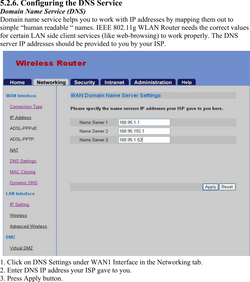
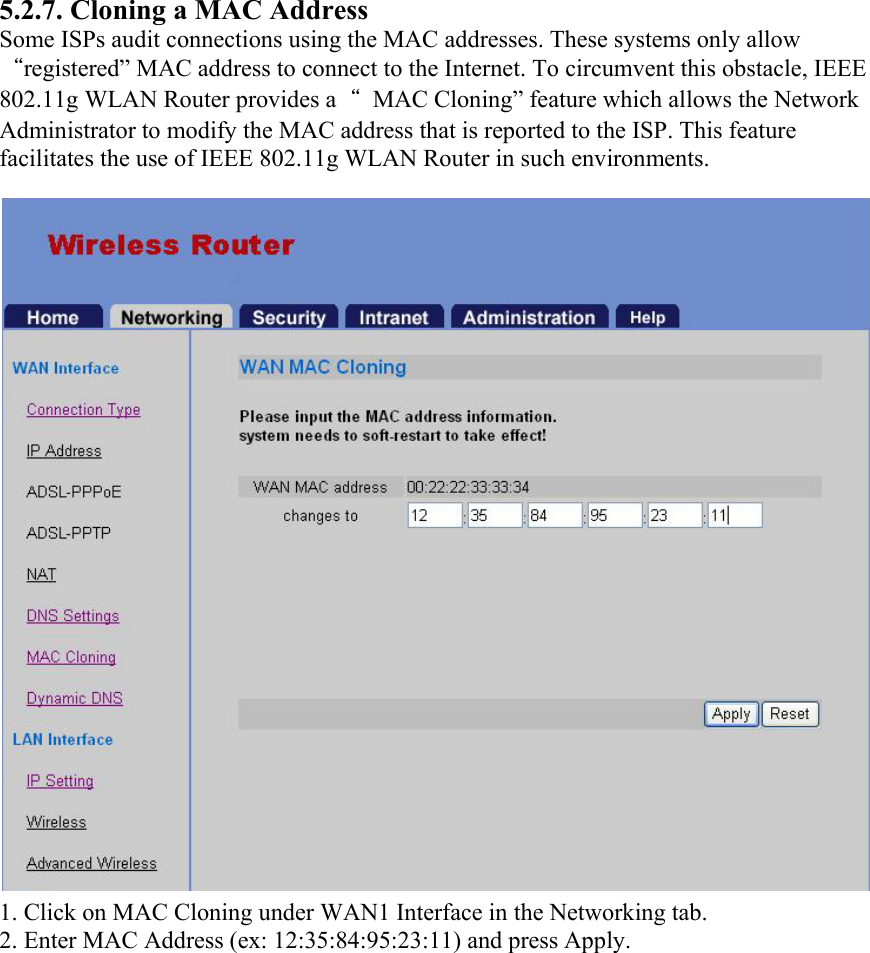
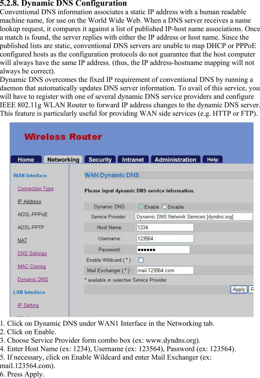
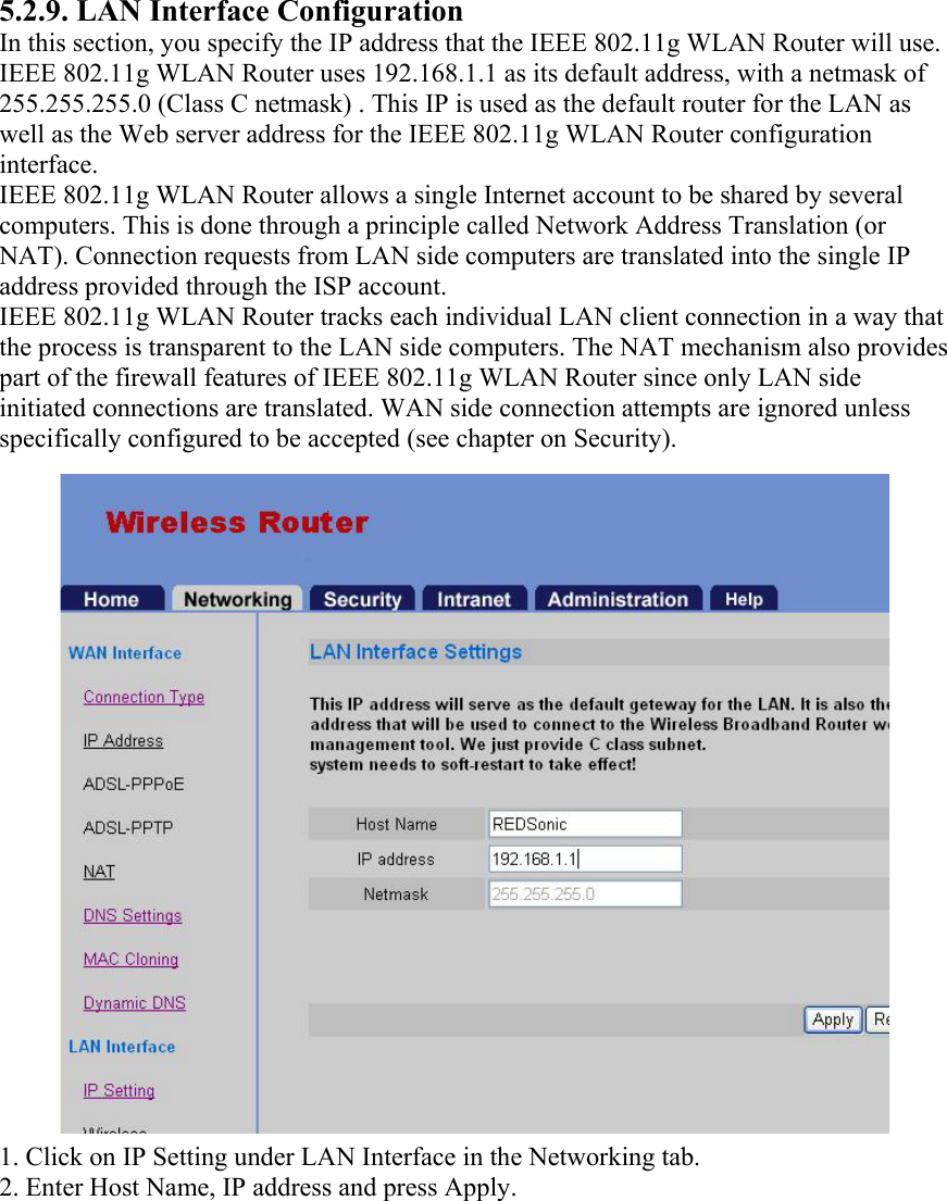
USERS MANUAL 1
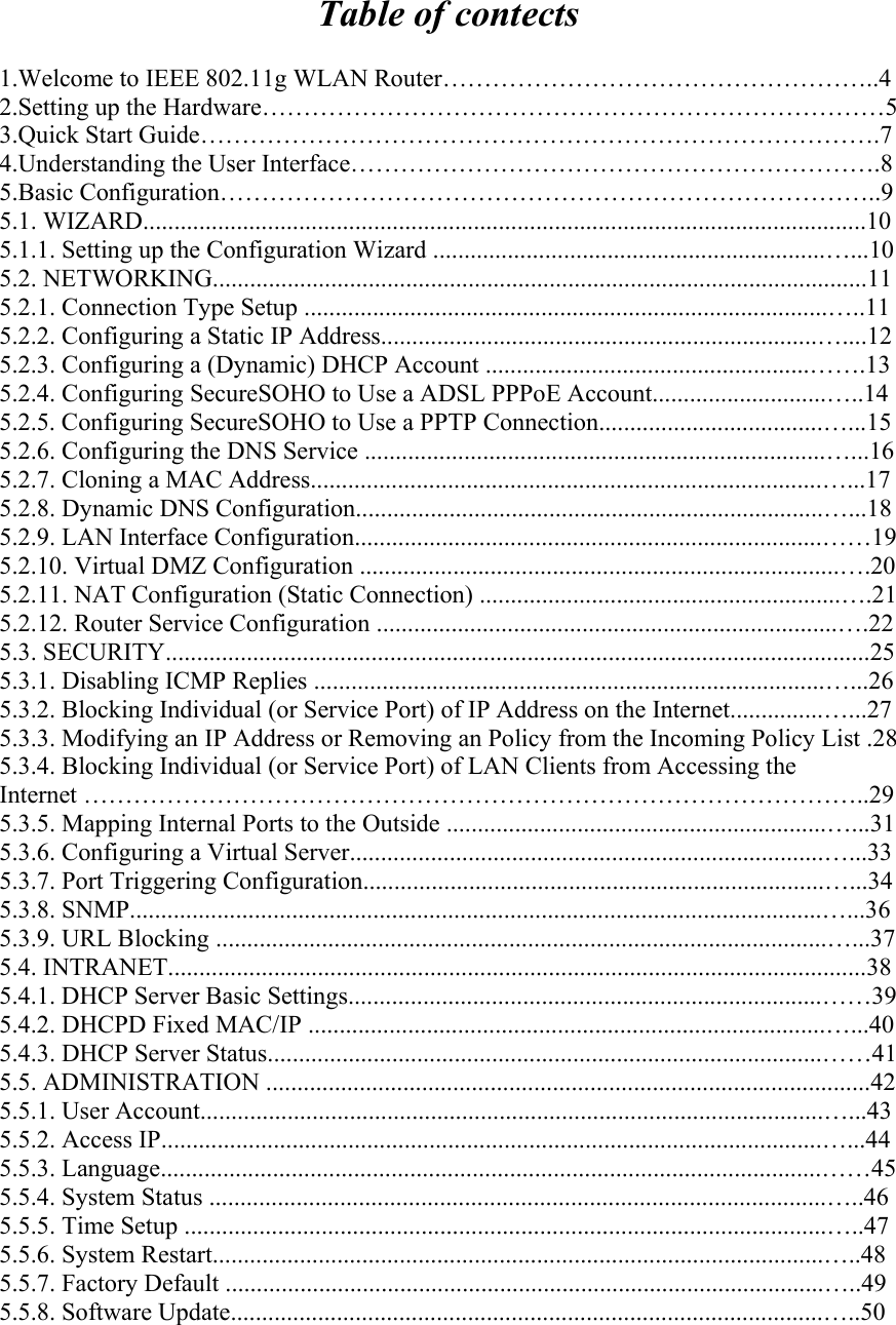
Contents
1.
USERS MANUAL 1
2.
USERS MANUAL 2
USERS MANUAL 1
Navigation menu
Upload a User Manual
Namespaces
Wiki Guide
HTML
PDF
Info
Views
User Manual
Discussion / Help
Navigation