User Manual.compressed


Preface
Thanks for choosing TK8X5L series industrial routers! This user’s manual will guide you in detail
on how to configure TK8X5L.
The preface includes the following contents:
Readers
Conventions in the Manual
Obtaining Documentation
Technical Support
Information Feedback
Readers
This manual is mainly intended for the following engineers:
Network planners
On-site technical support and maintenance personnel
Network administrators responsible for network configuration and maintenance
Conventions in the Manual
1. Format Conventions on Command Line
Format
Significance
Bold
Keywords of command line (the part that should be remained unchanged in
command and be entered as it is) are expressed with bold font.
Italic
The parameters of command line (the part that must be replaced with the actual
value in command) are expressed in italic.
[ ]
Indicating that the part in “[]” is optional in command configuration.
{ x | y | ... }
Indicating to select one from multiple options.
[ x | y | ... ]
Indicating to select one or not to select from multiple options.
{ x | y | ... } *
Indicating to select at least one from multiple options.
[ x | y | ... ] *
Indicating to select one or more or not to select from multiple options.
&<1-n>
Indicating that the parameter in front of the symbol & can be repeatedly entered
for 1~n times.
#
The lines starting from no. “#” are comment lines.
2. Format Conventions on Graphic Interface
Format
Significance
2

<>
[ ]
/
The content in angle brackets "<>" indicates button name, e.g. "click <OK>
button.”
The content in square brackets "[]" indicates window name, menu name or data
sheet, e.g. “pop-up the [New User] window”.
Multi-level menu is separated by "/". For example, the multi-level menu [File /
New / Folder] indicates the menu item [Folder] under the submenu [New]
under the menu [File].
3. Various Signs
The manual also uses a variety of eye-catching signs to indicate the places to which special
attention should be paid in operation. The significances of these signs are as follows:
It indicates matters to be noted. Improper operation may cause
data loss or damage to the device.
The necessary complement or description on the contents of
operation.
Obtaining Documentation
The latest product information is available on the website of Welotec (www.welotec.com):
The main columns related to product information on the website of Welotec are described as follows:
[Service Support / Document Center]: Product information in terms of hardware installation,
software upgrade, configuration, etc., is available.
[Product Technology]: Documents on product introduction and technology introduction
including relevant introduction on product, technical introduction, technical white papers, etc.,
are available.
[Service Support / Software Download]: The supporting information on software version is
available.
Technical Support
E-mail: support@welotec.com
Website: www.welotec.com
Information Feedback
If you have any question on product information in use, you can feed back through the following
ways:
E-mail:info@welotec.com
Thanks for your feedback to let us do better!
3

CONTENTS
TK8X5L SERIE ..............................................................................................................................................................
1
USER'S MANUAL ...........................................................................................................................................................
1
VERSION: V3.0 ................................................................................................................................................................
1
PREFACE..........................................................................................................................................................................
2
READERS .........................................................................................................................................................................
2
CONVENTIONS IN THE MANUAL .............................................................................................................................
2
TECHNICAL SUPPORT .................................................................................................................................................
3
E-MAIL: SUPPORT@WELOTEC.COM ......................................................................................................................
3
INFORMATION FEEDBACK ........................................................................................................................................
3
E-MAIL
:
INFO@WELOTEC.COM ............................................................................................................................
3
1. TK8X5L
INTRODUCTION ............................................................................................................................................
7
1.1 Overview ..............................................................................................................................................................
7
1.2 Product Features ...................................................................................................................................................
7
2. LOGIN ROUTER .......................................................................................................................................................
11
2.1 Establish Network Connection .............................................................................................................................
11
2.1.1 Automatic acquisition of IP address (recommended) ..................................................................... ....................
11
2.1.2 Set a static IP address ..........................................................................................................................................
14
2.2 Confirm that the network between the supervisory PC and router is connected .................................................
15
2.3 Cancel the Proxy Server .......................................................................................................................................
16
3. WEB CONFIGURATION .........................................................................................................................................
19
3.1 Login the Web Setting Page of Router .................................................................................... ..............................
19
3.2 Management ............................................................................................................... ........................................
20
3.2.1 System .................................................................................................................................................................
20
3.2.2 System Time .........................................................................................................................................................
21
4

3.2.3 Admin Access ....................................................................................................................................................... 24
3.2.4 AAA ...................................................................................................................................................................... 28
3.2.5 Configuration Management ................................................................................................................................ 32
3.2.6 SNMP ................................................................................................................................................................... 33
3.2.7 Alarm ................................................................................................................................................................... 36
3.2.8 System Log ........................................................................................................................................................... 40
3.2.9 System Upgrading ................................................................................................................................................ 41
3.2.10 Reboot ............................................................................................................................................................... 42
3.3 Network ............................................................................................................................................................. 42
3.3.1 Ethernet Port ....................................................................................................................................................... 42
3.3.2 Dialup Port ........................................................................................................................................................... 45
3.3.3 PPPoE ................................................................................................................................................................... 49
3.3.4 Loopback .............................................................................................................................................................. 50
3.3.5 DHCP service ........................................................................................................................................................ 50
3.3.6 DNS Services ........................................................................................................................................................ 54
3.3.7 Dynamic Domain Name ....................................................................................................................................... 55
3.3.8 SMS ...................................................................................................................................................................... 57
3.4 Link Backup......................................................................................................................................................... 58
3.4.1 SLA ....................................................................................................................................................................... 58
3.4.2 Track Module ....................................................................................................................................................... 59
3.4.3 VRRP .................................................................................................................................................................... 60
3.4.4 Interface Backup .................................................................................................................................................. 65
3.5 Routing ............................................................................................................................................................... 69
3.5.1 Static Route.......................................................................................................................................................... 69
3.5.2 Dynamic Routing .................................................................................................................................................. 71
3.5.3 Multicast Routing................................................................................................................................................. 80
3.6 Firewall ............................................................................................................................................................... 82
3.6.1 Access Control ..................................................................................................................................................... 83
3.6.2 NAT ...................................................................................................................................................................... 87
3.7Qos ...................................................................................................................................................................... 91
3.7.1QoS ....................................................................................................................................................................... 93
3.7.2 QoS Application Example ..................................................................................................................................... 94
3.8VPN ..................................................................................................................................................................... 94
3.8.1IPSec ..................................................................................................................................................................... 95
3.8.2GRE ..................................................................................................................................................................... 102
3.8.3 DMVPN .............................................................................................................................................................. 104
3.8.4L2TP .................................................................................................................................................................... 111
3.8.5OPENVPN ............................................................................................................................................................ 112
3.8.6 Certificate Management .................................................................................................................................... 116
3.9 Industrial .......................................................................................................................................................... 116
3.9.1 DTU .................................................................................................................................................................... 117
5

3.9.2 IO ....................................................................................................................................................................... 120
3.10 Tools ............................................................................................................................................................... 121
3.10.1PING .................................................................................................................................................................. 121
3.10.2 Routing detection ............................................................................................................................................ 122
3.10.3 Link Speed Test ................................................................................................................................................ 123
3.11 Configuration Wizard ...................................................................................................................................... 123
3.11.1 New LAN .......................................................................................................................................................... 123
3.11.2 New WAN ........................................................................................................................................................ 124
3.11.3 New Cellular..................................................................................................................................................... 124
3.11.4 New IPSec Tunnel ............................................................................................................................................ 125
3.11.5 New Port Mapping ........................................................................................................................................... 126
3.12 Network Mode ............................................................................................................................................... 126
3.12.1 Cellular ............................................................................................................................................................. 126
3.12.2 ADSL Dialup (PPPoE) ........................................................................................................................................ 126
APPENDIX 1 TROUBLESHOOTING ...................................................................................................................... 128
APPENDIX 2 INSTRUCTION OF COMMAND LINE ........................................................................................... 130
APPENDIX 3 GLOSSARY OF TERMS .................................................................................................................... 136
APPENDIX 4 DESCRIPTION OF LEDS .................................................................................................................. 138
6

1. TK8X5L Introduction
This chapter includes the following parts:
Overview
Product Features
1.1 Overview
Thanks for choosing TK8X5L series industrial router. TK8X5L is the new generation of industrial
router developed by Welotec for M2M in 4G era.
Integrating 4G LTE and various broadband WANs, TK8X5L provides uninterrupted access to
internet. With the features of complete security and wireless service, TK8X5L can connect up to ten
thousand devices. TK8X5L has also been built for rapid deployment and easy management, which
enables enterprises to quickly set up large scale industrial network with minimized cost and time.
There are currently three TK8X5L series: TK8x2, TK8x5 which can provide up to 5 intelligent
ports and they support LAN/WAN protocol. TK8X5L products not only offer more options on
WAN port access, but also effectively save additional purchasing cost on switch equipment.
1.2 Product Features
7

Uninterrupted Access to Internet from Anywhere
Redundant WAN connection, 2 Ethernet ports, 3G/4G embedded, various DSL, TK8X5L is
built to support various WAN and ensure network availability. Whether the device is located in
commercial region or wild field, it can always keep on line with broadband service or
widespread 3G/4G connection. Furthermore, TK8X5L can automatically switch over between
broadband and 3G/4G when one link is failed, so as to ensure uninterrupted WAN connection.
With TK8X5L, your business is always online.
Support Large Scale Deployment
In your M2M application, there are thousands of remote machines, or tens of thousands of VPN
connection, which turns out to be a big challenge for network management. TK8X5L make
large scale deployment much easier with following features:
Multiple configuration tools including Web and CLI, enable administrator to rapidly
configure thousands of TK8X5L
Remote Network Management: TK8X5L works with network management platforms installed
in application center or headquarter. To remotely batch configure, download and upload
configuration file, upgrade firmware, monitor status of connection and VPN tunnel… all
these become essential for operating a M2M system especially when a large number of
devices scatter widely with limited field staff or even totally unattended.
TK8X5L supports industrial standard SNMP and 3rd SNMP software platform, so as to
integrate into enterprise level IT management system.
TK8X5L also collaborates with Welotec Device Manager to handle cellular specialty of
network management. Welotec Device Manager can be cloud based or installed within
enterprise’s intranet. Welotec Device Manager improves for cellular circumstance to
monitor cellular data flow, signal strength on site, location of the device. Even better,
there’s no need to apply costly private network from telecomm operator, and you can build
your worldwide M2M system across multiple operators.
Multiple diagnostic tools, supporting 3G/4G modem status, IMEI, IMSI and registration
status of cellular networks, help engineer out of complex network circumstance.
Support dynamic routing of RIP, OSPF, automatically update routing of whole network,
largely increase efficiency of large scale deployment.
Support Dynamic Multipoint VPN (DM VPN), greatly reduce workload to configure
8

thousands of remote TK8X5L. Establishing a large & secured remote network never made
so
easy!
Robust Security
Secured VPN Connections
Support GRE, L2TP, IPSec VPN, DMVPN, OpenVPN; CA, ensure data security
Security of Network
Support firewall functions to protect from network attacks, such as: Stateful Packet
Inspection (SPI), Access Control List (ACL), resist DoS attack, intrusion protection, attack
protection, IP/MAC Binding and etc.
Security of Devices
Support AAA, TACACS, Radius, LDAP, local authentication, and multi levels user
authority, so as to establish a secured mechanism on centralized authentication and
authorization of device access.
High Reliability
Redundancy
WAN Redundancy: support link backup, VRRP to support automatic switch over between
WANs.
Dual SIM cards: backup between different mobile operators to ensure networks availability
and bargaining power on data plan.
Automatic Link Detection & Recovery
PPP Layer Detection: keep the connection with mobile network, prevent forced hibernation,
able to detect dial link stability.
Network connection Detection: automatic redial when link broken, keep Long Connection.
VPN Tunnel Detection: sustain VPN tunnel, to ensure availability of business.
TK8X5L Auto-recovery
TK8X5L embeds hardware watchdog, able to automatically recover from various failure,
ensure highest level of availability.
Entirely Ruggedized
TK8X5L inherits Welotec Networks’ legacy on best-in-class ruggedized design. From
component

selection to circuit layout, TK8X5L satisfies electric power and industrial applications on EMC, IP
9

protection, temperature range and etc. TK8X5L is designed to last in harshest circumstances.
High Performance, High Bandwidth
Equipped with powerful Cortex-A8 processor and 256MB memory, support more
application needs
Support 4G/LTE (100Mbps downlink and 50Mbps uplink) and HSPA+ (21Mbps downlink
and 5.76Mbps uplink)
Welotec Network Operation System: INOS 2.0
Welotec Network Operation System (INOS) has been built as the highly reliable & real-time
basis for all network functions, as well as easy-to-use configuration interface via Web, CLI or
SNMP. INOS is in modular design, expandable, and adaptable to various M2M applications.
Embed WIFI AP and Client, Easy to Establish Versatile Wireless Network
Support 802.11 b/g/n standard, fulfill the need to connect WLAN devices, up to 150Mbps
throughput
Easily establish wireless LAN, support WEP/WPA/WPA2 for network security
WIFI can be the backup WAN link for 3G/4G
10
2. Login Router
This chapter mainly contains the following contents:
Establish Network Connection
Confirm that the connection between supervisory PC and router
Cancel the Proxy Server
2.1 Establish Network Connection
2.1.1 Automatic acquisition of IP address (recommended)
Please set the supervisory computer to "automatic acquisition of IP address" and "automatic
acquisition of DNS server address" (default configuration of computer system) to let the router
automatically assign IP address for supervisory computer.
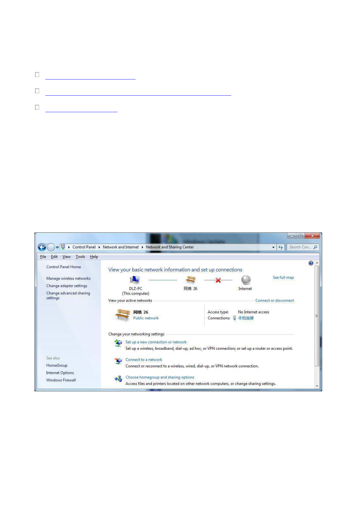
1) Open “Control Panel”, double click “Network and Internet” icon, enter “Network and Sharing
Centers”
2) Click the button <Local Connection> to enter the window of "Local Connection Status”
11
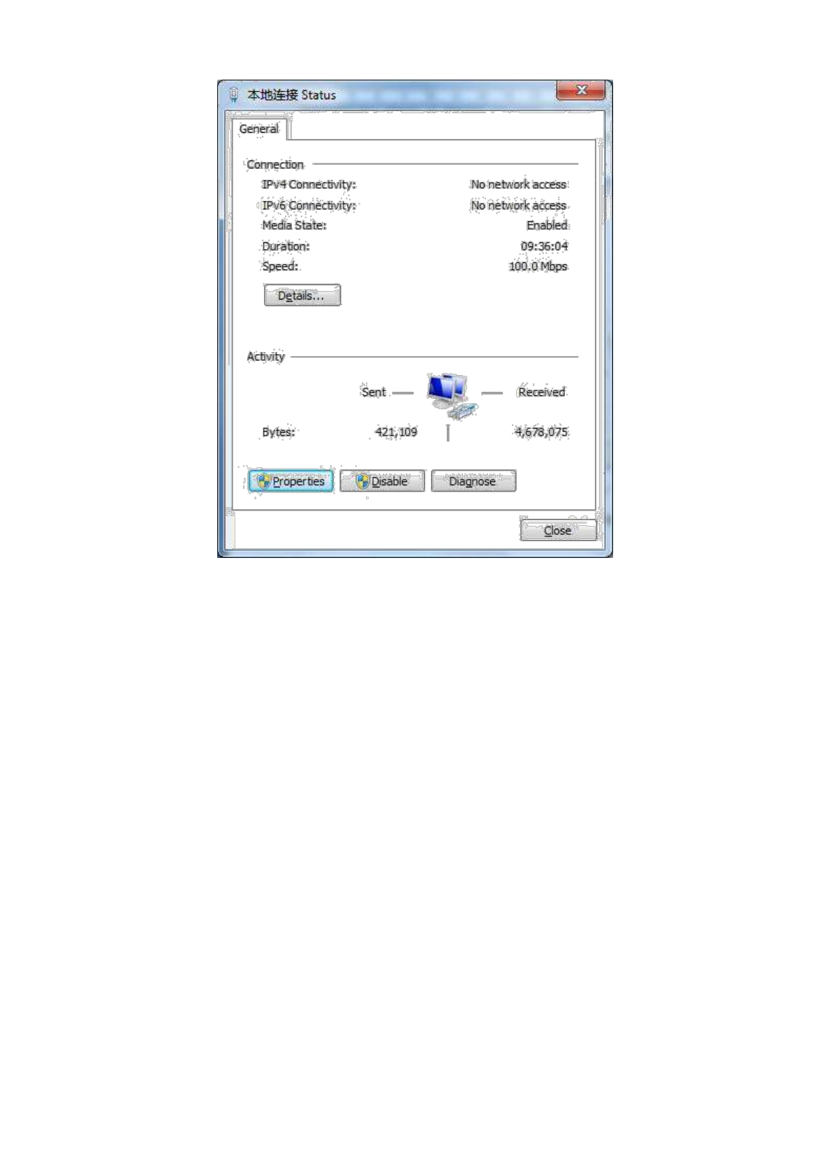
3) Click <Properties>to enter the window of "Local Connection Properties”, as shown below.
12
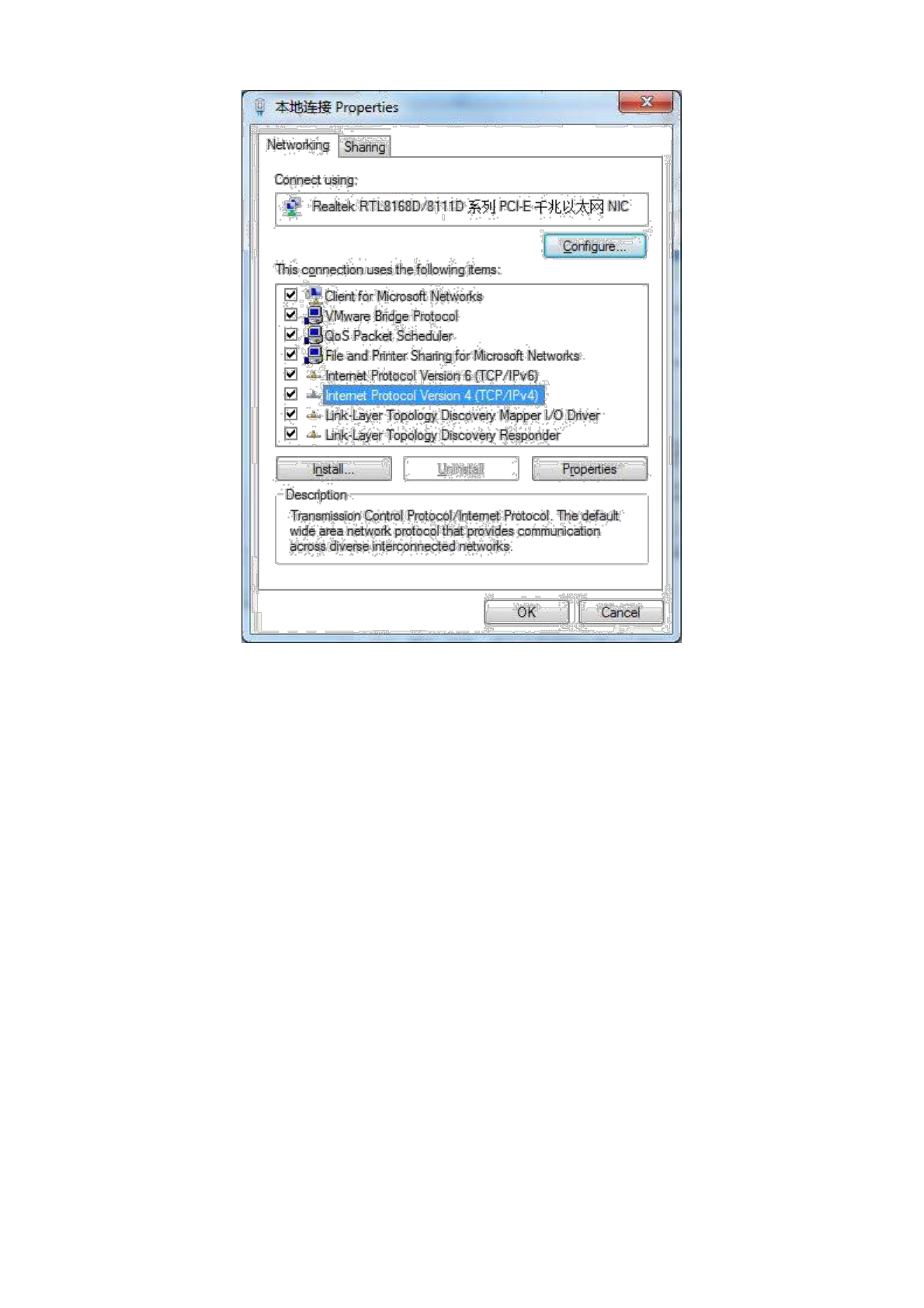
4) Select “Internet Portocol Version 4(TCP/IPv4)”, click <Properties> to enter “Internet Portocol
Version 4 (TCP/IPv4) Properties” page. Select “Obtain an IP address automatically” and “Obtain
DNS Server address automatically”, then click <OK> to finish setting, as shown below.
13
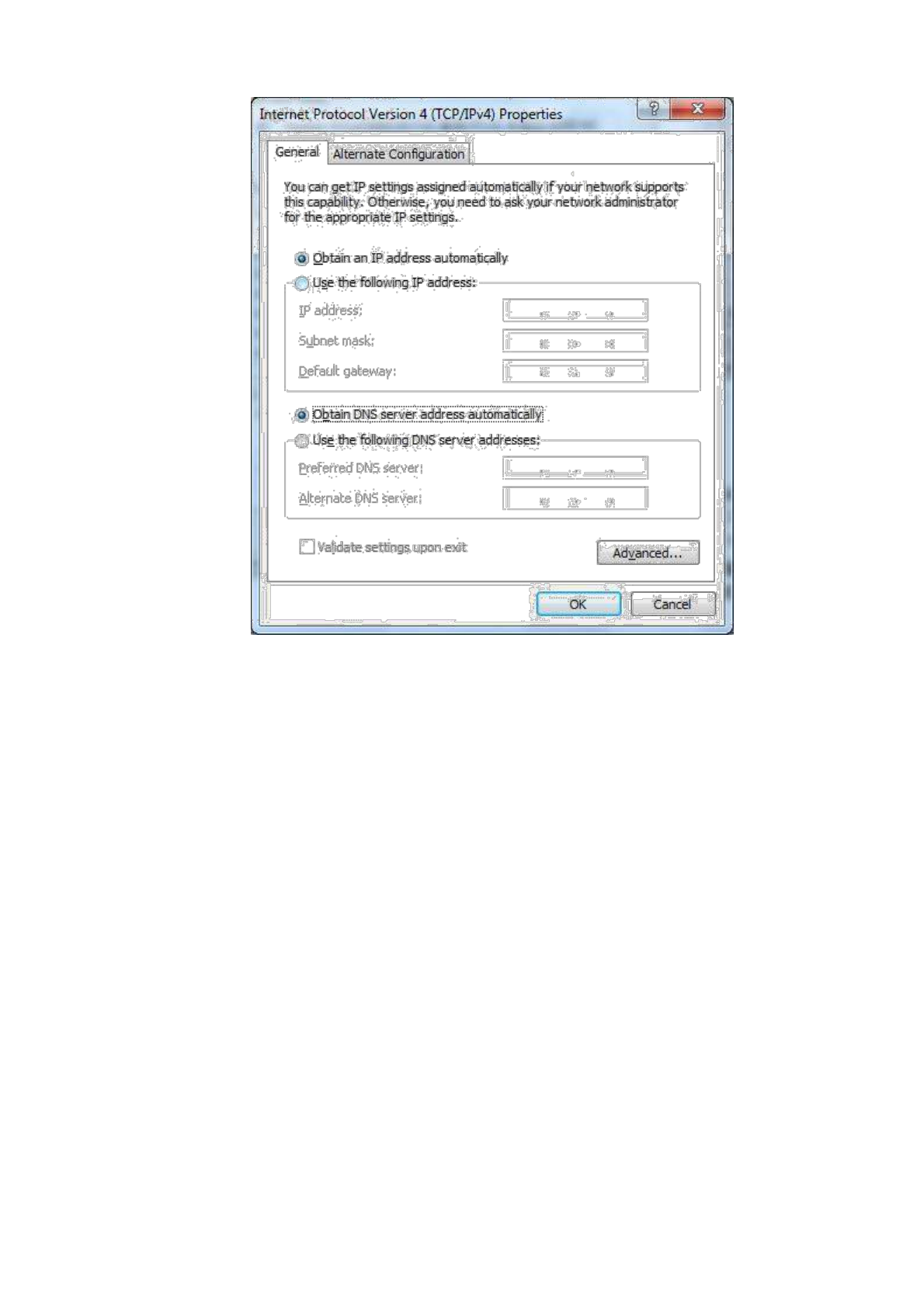
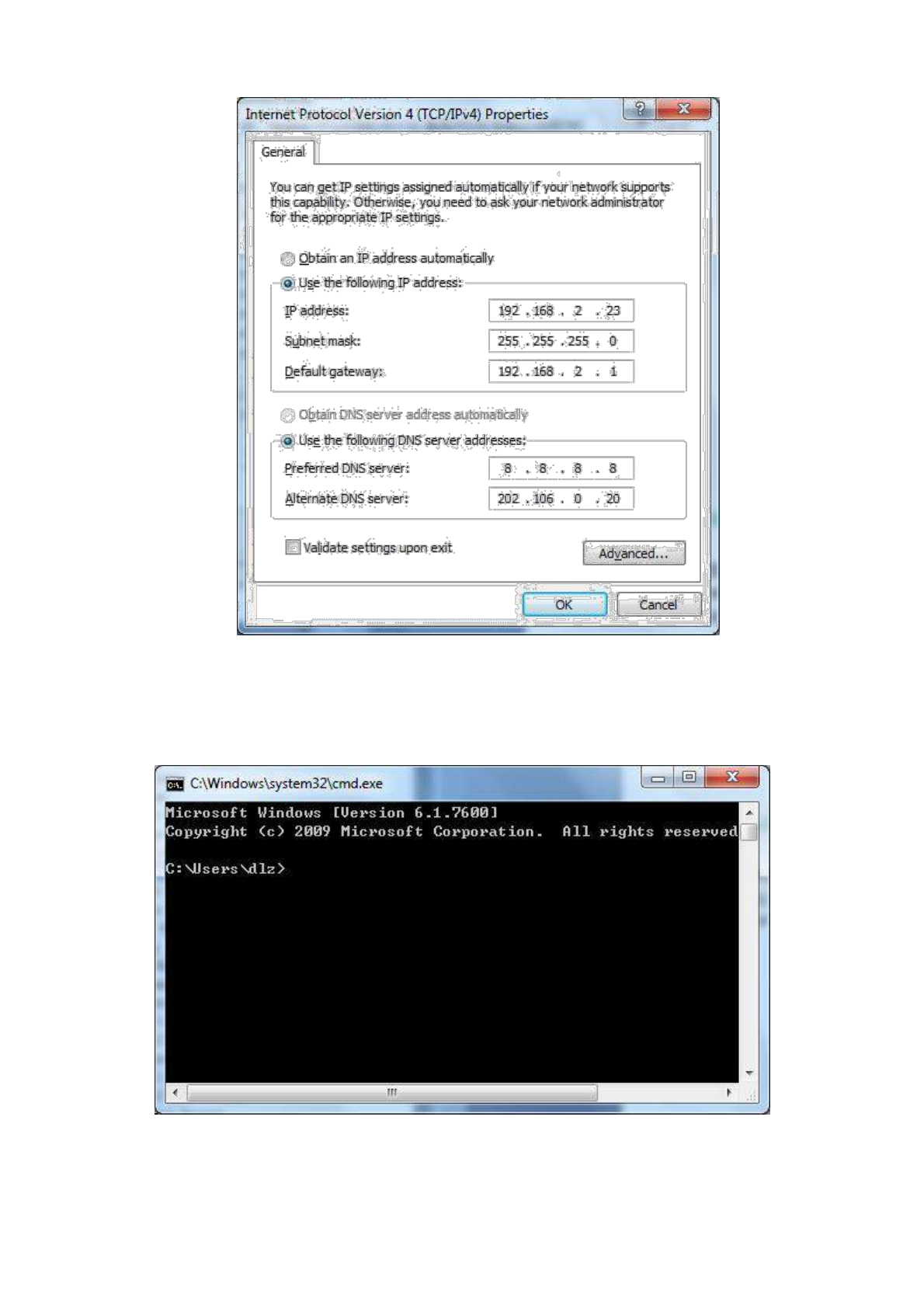
2.1.2 Set a static IP address
Enter “Internet Portocol Version 4 (TCP/IPv4)Properties” page, select “Use the following IP
address”, type IP address (arbitrary value between 192.168.2.2 ~192.168.2.254), Subnet Mask
(255.255.255.0), and Defafult Gateway (192.168.2.1), then click <OK>to finish setting, as shown
below.
14
2.2 Confirm that the network between the supervisory PC and router is connected
1) Click the button <Start> at the lower left corner to research “cmd.exe”, and run cmd.exe
2) Enter "ping 192.168.2.1 (IP address of router; it is the default IP address), and click the button
<OK>. If the pop-up dialog box shows the response returned from the router side, it indicates that the
15
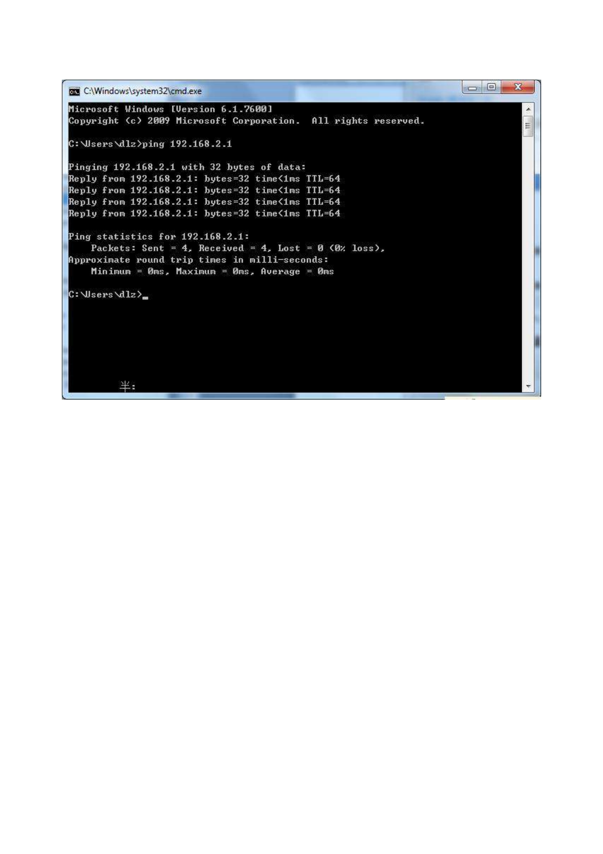
network is connected; otherwise, check the network connection.
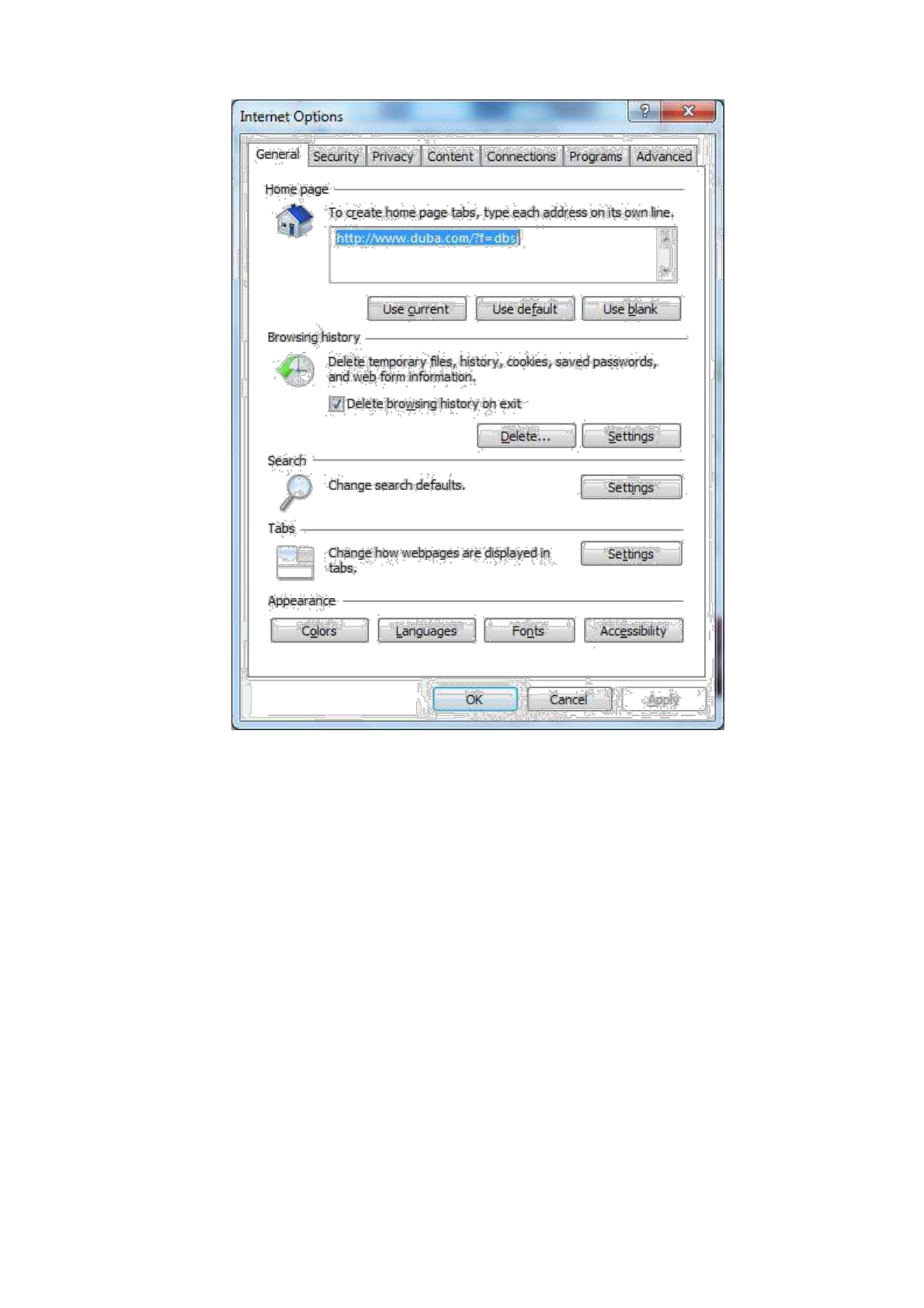
2.3 Cancel the Proxy Server
If the current supervisory computer uses a proxy server to access the Internet, it is required to
cancel the proxy service and the operating steps are as follows:
(1) Select [Tools/Internet OPtions] in the browser to enter the window of [Internet Options]
16
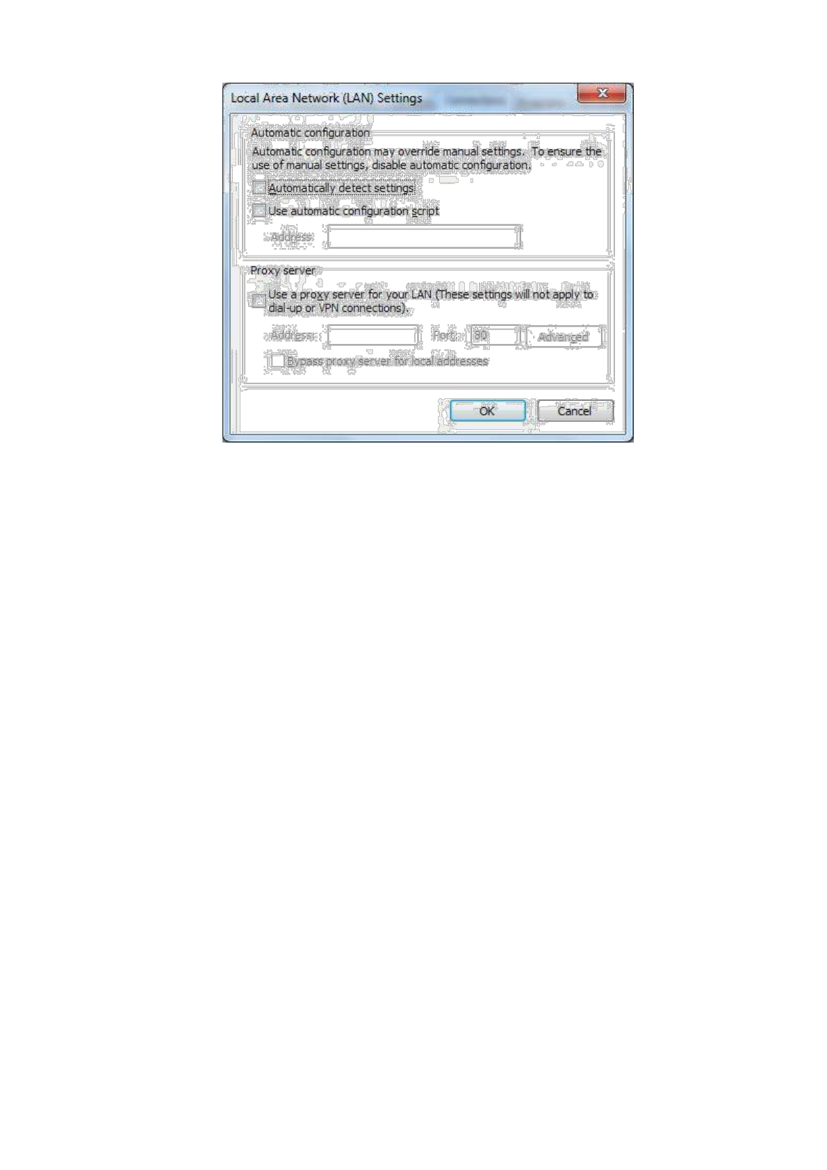
(2) Select the tab”Connect” and click the button<LAN Setting(L)> to enter the page of “LAN
Setting”.Please confirm if the option”Use a Proxy Server for LAN” is checked;if it is
checked,please cancel and click the button<OK>.
17
18
3. Web Configuration
This chapter includes the following parts:
Login/out Web Configuration Page
Management
Network
Link Backup
Routing
Firewall
QOS
VPN
Tools
Installation Guide
3.1 Login the Web Setting Page of Router
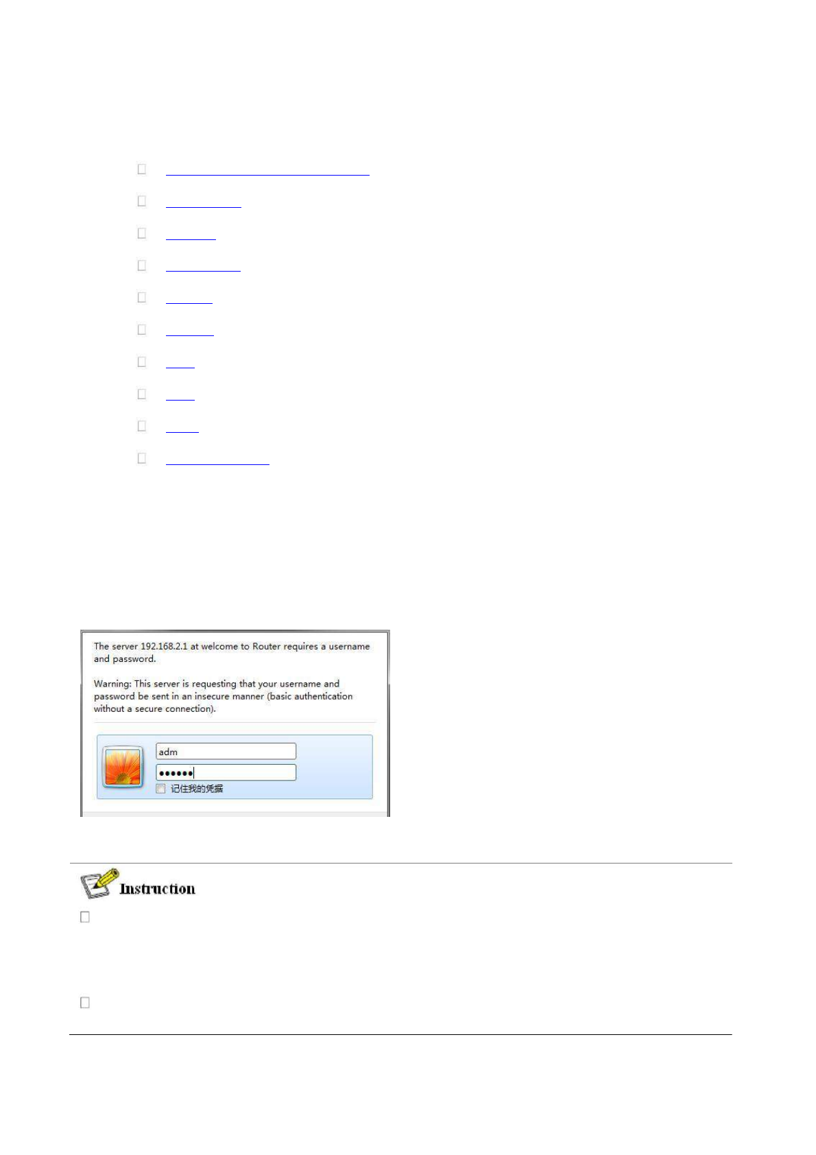
Run the Web browser, enter “http://192.168.2.1” in the address bar, and press Enter to skip to
the Web login page, as shown in Figure 3-1. Enter the “User Name” (default: adm) and “Password”
(default: 123456), and click button <OK> or directly press Enter to enter the Web setting page.
At the same time, the router allows up to four users to manage through the Web setting page.
When multi-user management is implemented for the router, it is suggested not to conduct
configuration operation for the router at the same time; otherwise it may lead to inconsistent
data configuration.
For security, you are suggested to modify the default login password after the first login and
safe keep the password information.
19
3.2 Management
3.2.1 System
3.2.2.1 System Status
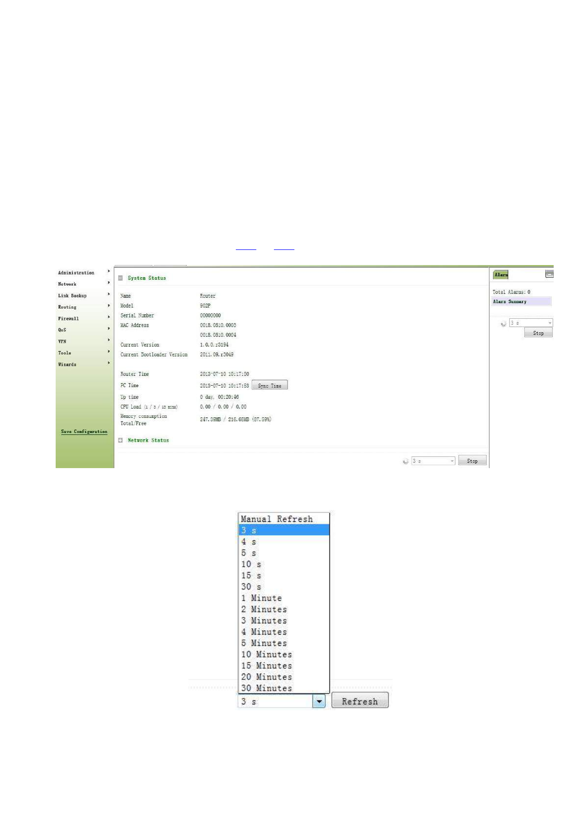
From the left navigation panel, select Administration << System, then enter “System Status” page. On this page
you can check system status and network status, as shown below. In system status, by clicking <Sync Time>you
can make the time of router synchronized with the system time of the host. Click the “Set” behind Cellular1,
Fastethernet 0/1 and Fastethernet 0/2 respectively on network status to enter into the configuration screen directly.
For configuration methods, refer to Section 3.3.1and 3.3.2.
User can define the refresh interval of the screen through the drop down list at the lower right corner of the screen.
3.2.1.2 Basic Settings
20

Select Administration << System, then enter “Basic Setup” page. You can set the language of Web
Configuration Page and define Router Name, as shown below.
Page description is shown below:
Parameter Name
Description
Default
Language
Select system language of Router
English
Router Name
Define Router Name
Router
3.2.2 System Time
To ensure the coordination between this device and other devices, user is required to set the system time in an
accurate way since this function is used to configure and check system time as well as system time zone.
The device supports manual setting of system time and the time to pass self-synchronistic SNTP server.
3.2.2.1 System Time
Time synchronization of router with connected host could be set up manually in system time configuration
part while system time is allowed to be set as any expected value after Year 2000 manually.
From the left navigation panel, select Administration >> System Time, then enter “System Time” page, as
shown below.
By clicking <Sync Time>you can make the time of router synchronized with the system time of the host. Select
the expected parameters in Year/Month/Date and Hour:Min:Sec colum, then click <Apply & Save>. The router
will immediately set the system time into expected value.
21

Page description is shown below:
Parameters
Description
Default
Router Time
System time of Router
1970.01.01
PC Time
Time of connected PC
None
Year/Month/Da
Set the expected Year/Month/Date
Current
te
Year/Month/Date
Hour:Min:Sec
Set the expected Hour:Min:Sec
Current
Hour:Min:Sec
Timezone
Set timezone
UTC+08:00
3.3.2.2 SNTP Client
SNTP, namely Simple Network Time Protocol, is a system for synchronizing the clocks of networked
computers as a computer network protocol and provides comprehensive mechanisms to access national time and
frequency dissemination services, organize the time-synchronization subnet and adjust the local clock in each
participating subnet peer. In most places of the Internet today, SNTP provides accuracies of 1-50ms depending on
the characteristics of the synchronization source and network paths.
The purpose of using SNTP is to achieve time synchronization of all devices equipped with a clock on
network so as to provide multiple applications based on uniform time.
From the left navigation panel, select Administration << System Time, then enter “SNTP Client” page, as
shown below.
22
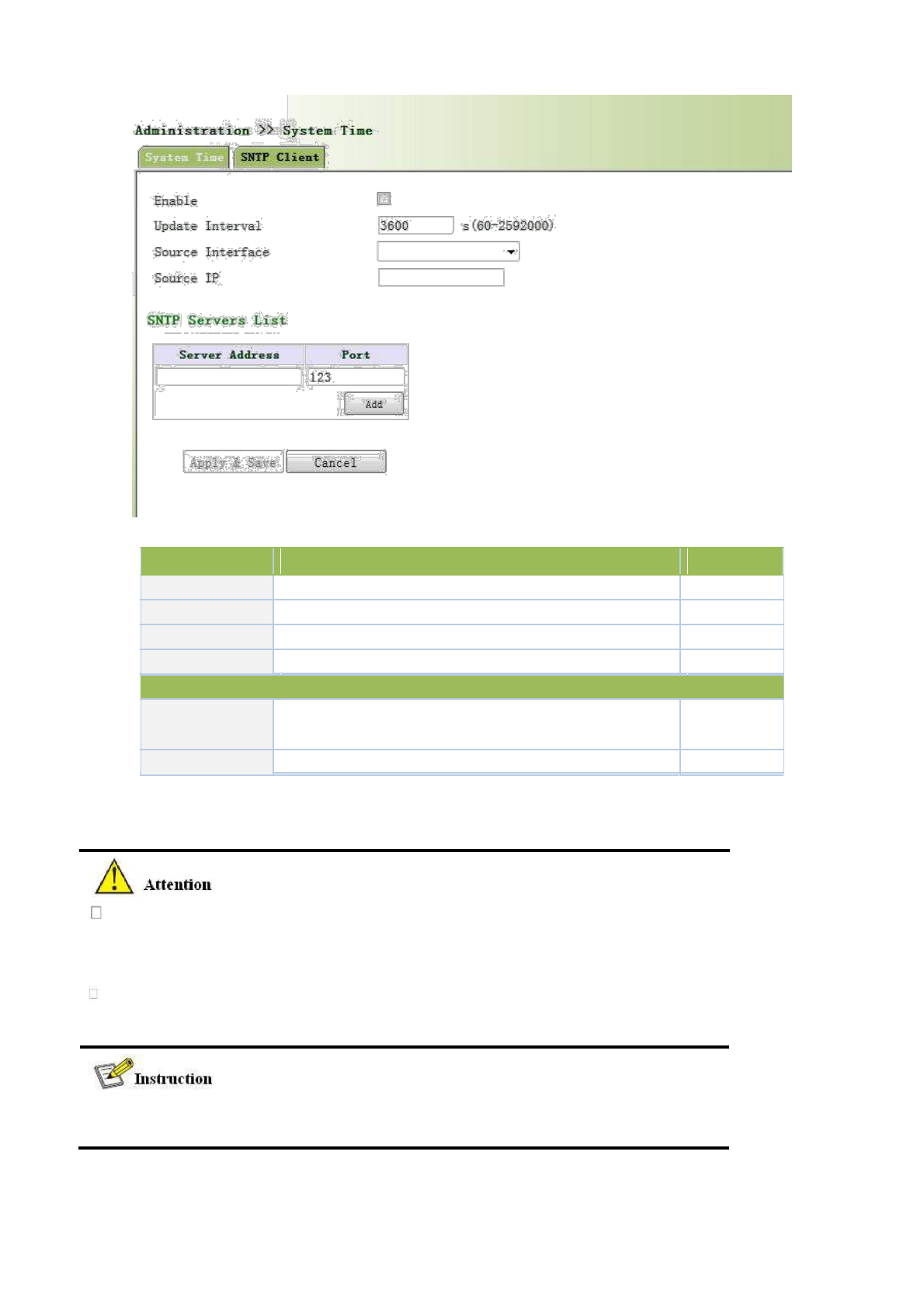
Page description is shown below:
Parameters
Description
Default
Enable
Enable/Disable SNTP client
Disable
Update Interval
Synchronization time intervals with SNTP server
3600
Source Interface
Cellular1,Fastethernet 0/1,Fastethernet 0/2
None
Source IP
The corresponding IP of source interface
None
SNTP Servers List
Server Address
SNTP server address (domain name /IP), maximum to set10
None
SNTP server
Port
The service port of SNTP server
123
The meanings of key items in the page are shown in the table below
Before setting a SNTP server, should ensure SNTP server reachable.
Especially when the IP address of SNTP server is domain, should ensure DNS
server has been configured correctly.
If you configure a source interface and then cannot configure the source address.
the opposite is also true
When setting multiple SNTP server, system will poll all SNTP servers
until find an available SNTP server.
23
3.2.3 Admin Access
Admin Access allows the management of users which are categorized into superuser and common user.
Superuser: only one automatically created by the system, allocated with the user name of adm and granted
with all access rights to the router.
Common user: created by superuser with the right to check rather then modify router configuration.
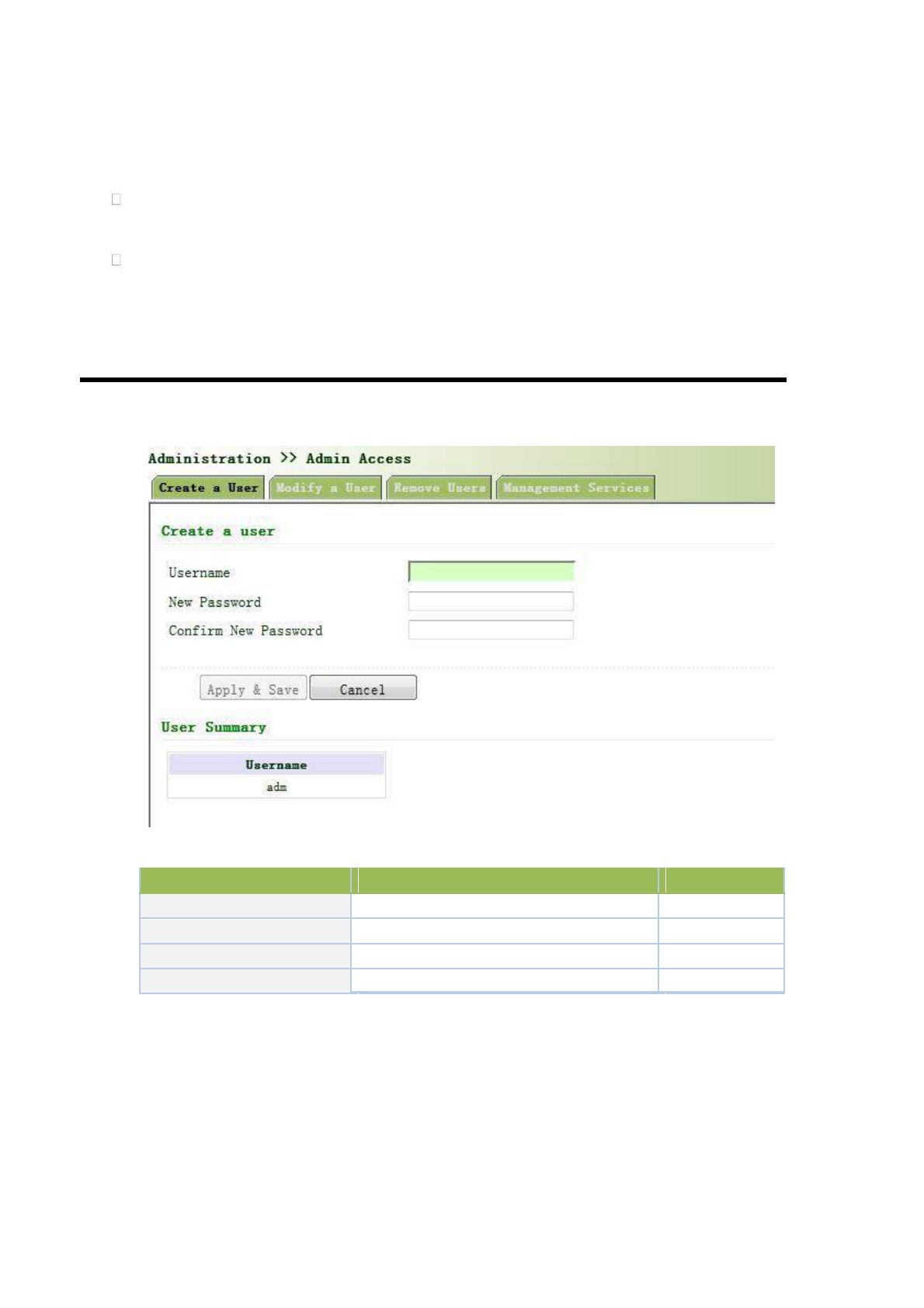
3.2.3.1 Create a User
Select Administration >>Admin Access, then enter “Create a User” page, as shown below.
Create a user
Page description is shown below:
Parameters
Description
Default
Username
New username
None
New Password
New password
None
Confirm New Password
Confirm the new password
None
User Summary
List all the users of current system
None
3.2.3.2 Modify a User
From the left navigation panel, select Administration << Admin Access, then enter “Modify a User” page,
as shown below.
Press the user that needs to modify in “User Summary”, after the background turns blue, enter new
information in “Modify a User”.
24
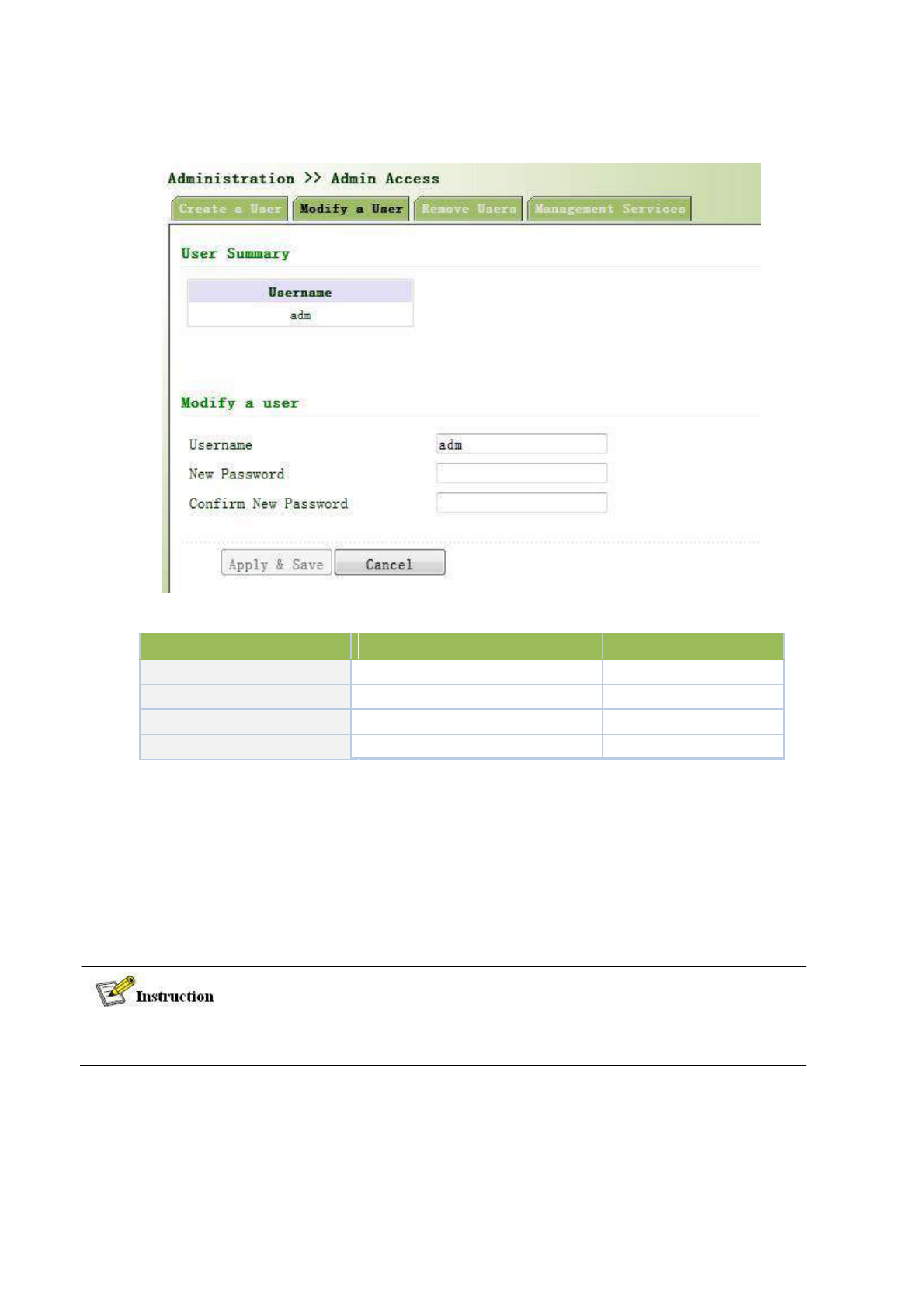
Modify user information
Page description is shown below:
Parameters
Description
Default
User Summary
List all the users of current system
adm
Username
The username needs to modify
None
New Password
New password
None
Confirm New Password
Confirm the new password
None
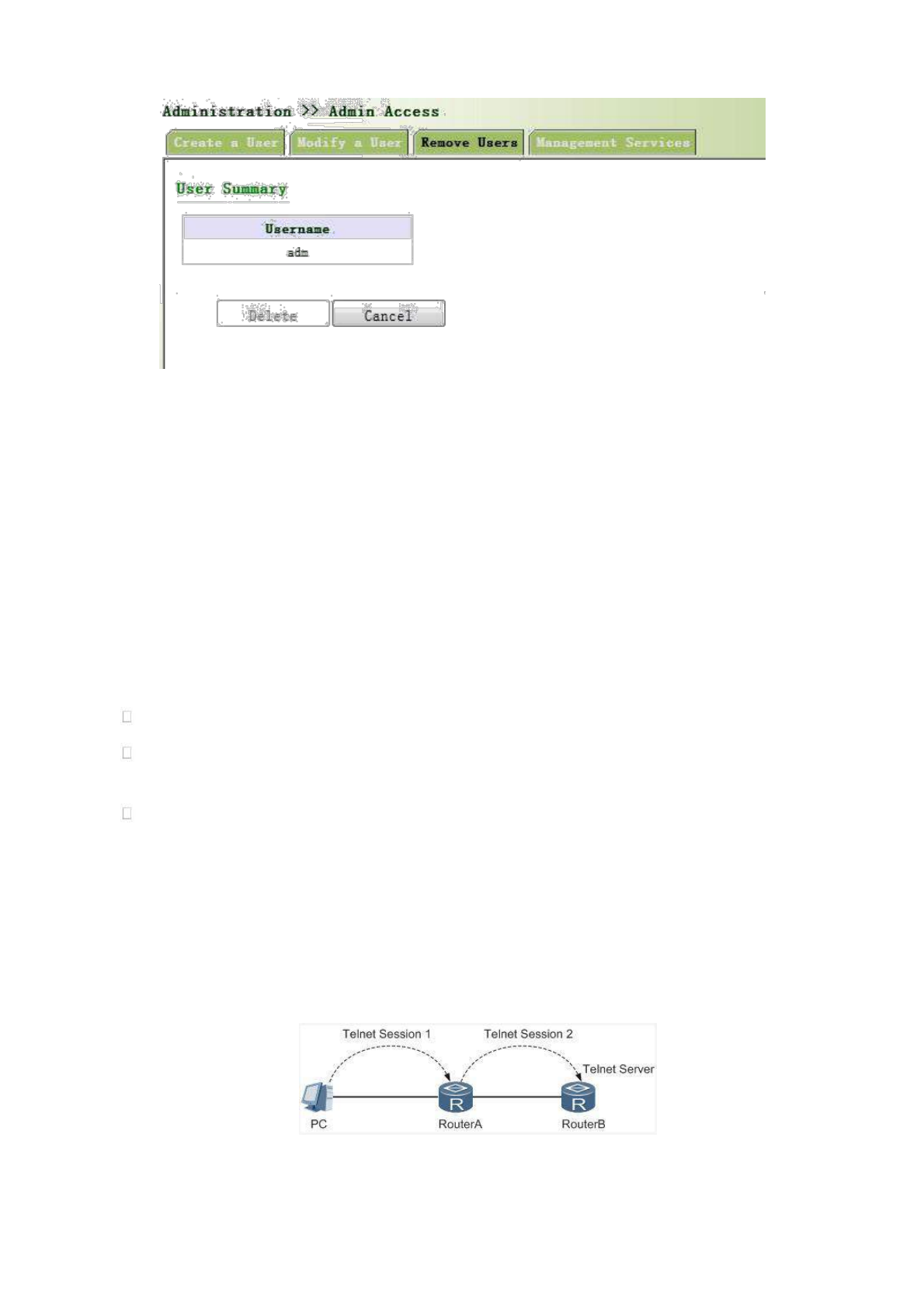
3.2.3.3 Remove Users
From the left navigation panel, select Administration << Admin Access, then enter “Remove Users” page,
as shown below.
Press the user that needs to remove in”User Summary”. After the background turns blue, press <Delete> to
remove the user.
The super user (adm) can neither be modified nor deleted. But super user’s password can be
modified.
25
3.2.3.4 Management Service
HTTP
HTTP, shortened form of Hypertext Transfer Protocol, is used to transmit Web page information on Internet.
HTTP is located as the application layer in TCP/IP protocol stack.
Through HTTP, user could log on the device to access and control it through Web.
HTTPS
HTTPS (Hypertext Transfer Protocol Secure) supports HTTP in SSL (Security Socket Layer).
HTTPS, depending on SSL, is able to improve the device’s security through following aspects:
Distinguish legal clients from illegal clients through SSL and forbidden illegal clients to access the device;
Encrypt the data exchanged between client and device to guarantee security and integrality of data
transmission so as to achieve the safe management of device;
An access control strategy based on certificate attributions is established for further control of client’s
access authority so as to further avoid attack for illegal clients.
TELNET
Telnet is an application layer protocol in TCP/IP protocol family, providing telnet and VT functions through
Web. Depending on Server/Client, Telnet Client could send request to Telnet server which provides Telnet
services. The device supports Telnet Client and Telnet Server.
Connection of Telnet is shown in following figure:
Router A now functions as the Telnet Server, but also provides Telnet Client service. Router B and Router A
provides Telnet Client function.
26
SSH
Telnet adopts TCP to execute Plaintext Transmit, lacking of secure authentication mode and being vulnerable
to DoS (Denial of Service), Host IP spoofing and routing spoofing and other malicious attacks, generating great
potential security hazards.
In comparison with Telnet, STelnet (Secure Telnet), based on SSH2, allows the Client to negotiate with
Server so as to establish secure connection. Client could log on Server just as operation of Telnet.
Through following measures SSH will realize the secure telnet on insecure network:
Support RAS authentication.
Support encryption algorithms such as DES, 3DES and AES128 to encrypt username password and data
transmission.
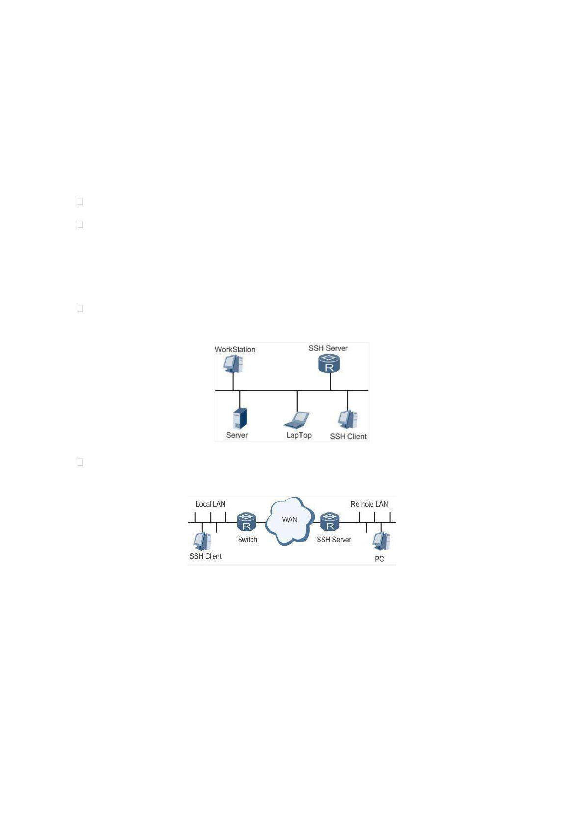
TK8X5L only supports SSH Server and could connect with multiple SSH Clients.
SSH supports local connection and WAN connection.
Local connection. A SSH channel could be established between SSH Client and SSH Server to achieve
local connection. Following is a figure showing the establishment of a SSH channel in LAN:
WAN connection. A SSH channel could be established between SSH Client and SSH Server to achieve
WAN connection. Following is a figure showing the establishment of a SSH channel in WAN:
From the left navigation panel, select Administration << Admin Access, then enter “Management
Service” page, as shown below.
27
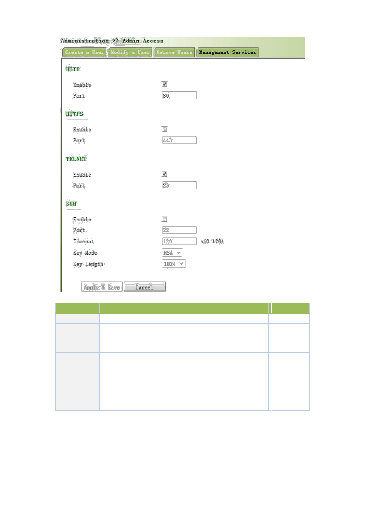
Page description is shown below:
Parameters
Description
Default
HTTP
Hypertext Transfer Protocol, Plaintext Transmission, Port: 80.
On
HTTPS
Secure SSL Encryption Transmission Protocol. Port: 443
Off
TELNET
Standard protocol and main way for Internet telnet service. Port:
On
23
Port: 22
Timeout: timeout of SSH session. No operation within this
SSH
period on SSH Client, SSH Server disconnect. Default: 120s
Off
Cipher Mode: set up public key encryption method (currently
only RSA supported). Cipher Code Length: set up cipher code
length, 512 or 1024. default: 1024
3.2.4 AAA
AAA access control is used to control visitors and corresponding services available as long as access is
allowed. Same method is adopted to configure three independent safety functions. It provides modularization
methods for following services:
28
Authentication: verify whether the user is qualified to access to the network.
Authorization: related with services available.
Charging: records of the utilization of network resources.
User may only use one or two safety services provided by AAA. For example, the company just wants
identity authentication when employees are accessing to some specified resources, then network administrator
only needs to configure authentication server. But if recording of the utilization of network is required, then, a
charging server shall be configured.
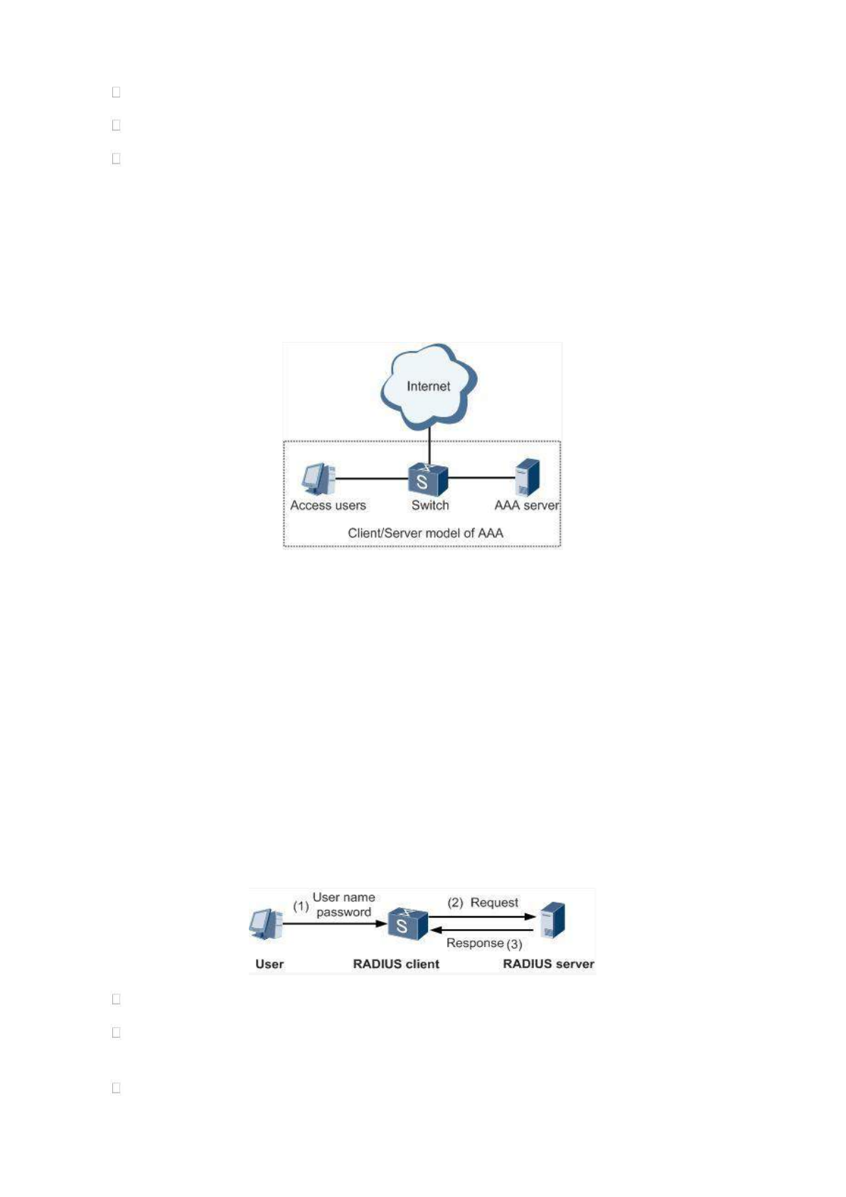
Commonly AAA adopts “Client—Server” structure which is featured by favorable expandability and
facilitates centralized management of users’ information, as the following figure shows:
3.2.4.1 Radius
Remote Authentication Dial-in User Service (RADIUS), an information exchange protocol with a
distributive Client/Server structure, could prevent the network from any disturbance from unauthorized access and
is generally applied in various network environments with higher requirements on security and that permit remote
user access. The protocol has defined the Radius frame format based on UDP and information transmission
mechanism, confirmed UDP Port 1812 as the authentication port. Radius Server generally runs on central
computer or workstation; Radius Client generally is located on NAS.
Initially Radius is designed and developed against AAA protocol of dial-in users. Along with the diversified
development of user access ways, Radius also adapts itself to such changes, including Ethernet access and ADSL
access. Access service is rendered through authentication and authorization.
Message flow between Radius Client and Server is shown as follows:
User name and passport will be sent to the NAS when the user logs on it;
Radius Client on NAS receives username and password and then sends an authentication request to
Radius Server;
Upon the reception of legal request, Radius Server executes authentication and feeds back required user
29
authorization information to Client; For illegal request, Radius Server will feed back Authentication
Failed to Client.
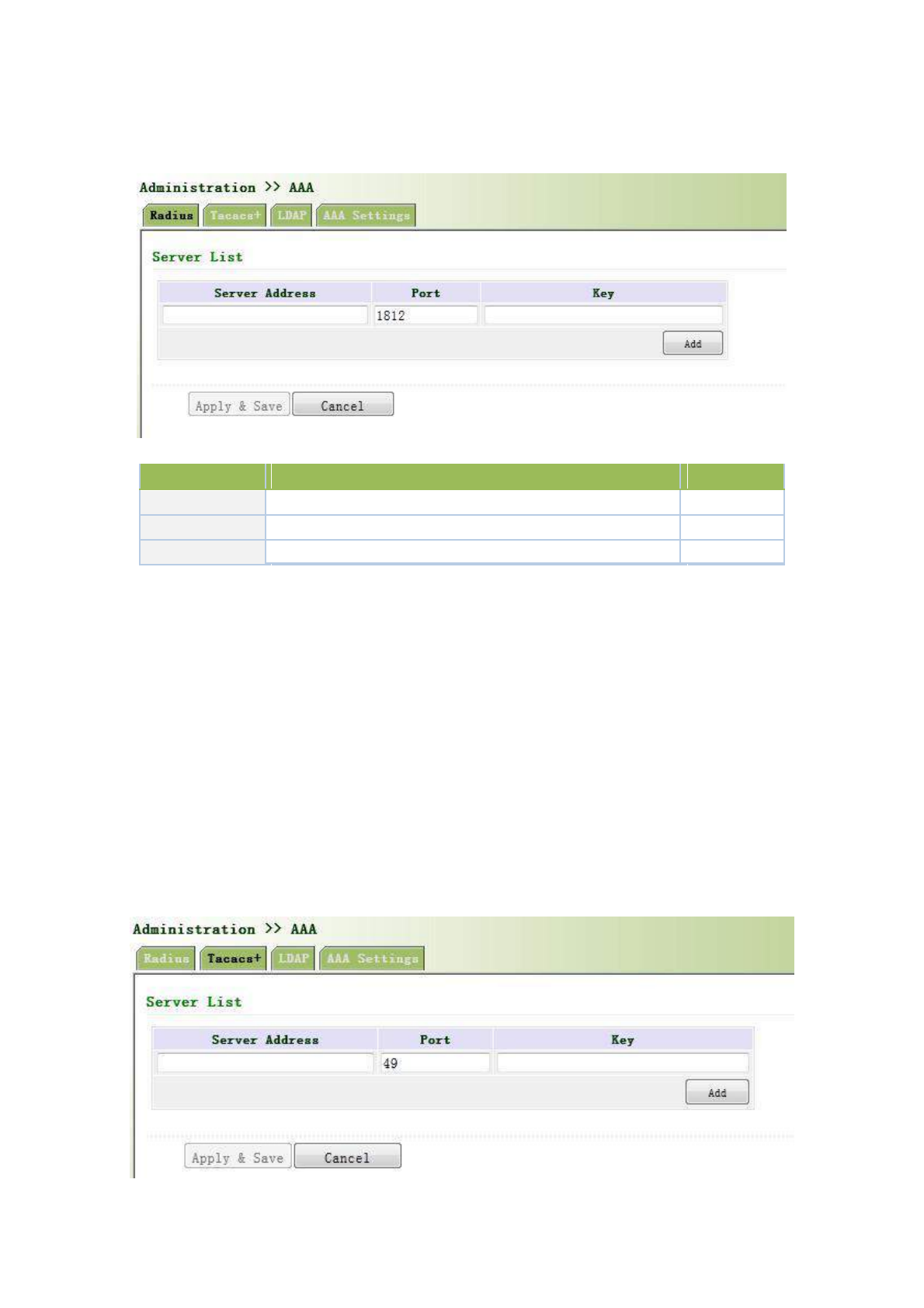
From the left navigation panel, select Administration << AAA, then enter “Radius” page, as shown below.
Page description is shown below:
Parameters
Description
Default
Server Address
Server address (domain name / IP)
None
Port
Consistent with the server port
1812
Key
Consistent with the server authentication key
None
3.2.4.2 Tacacs+
Tacacs+, or Terminal Access Controller Access Control System, similar to Radius, adopts Client/Server
mode to achieve the communication between NAS and Tacacs+ Server. But, Tacacs+ adopts TCP while Radius
adopts UDP.
Tacacs+ ismainly used for authentication, authorization and charging of access users and terminal users
adopting PPP and VPDN. Its typical application is authentication, authorization and charging for terminal users
requiring logging on the device to carry out operation. As the Client, the device will have username and password
sent to Tacacs+ Server for verification. So long as user verification passed and authorization obtained, logging and
operation on the device are allowed.
From the left navigation panel, select Administration << AAA, then enter “Tacacs+” page, as shown below.
Page description is shown below:
30
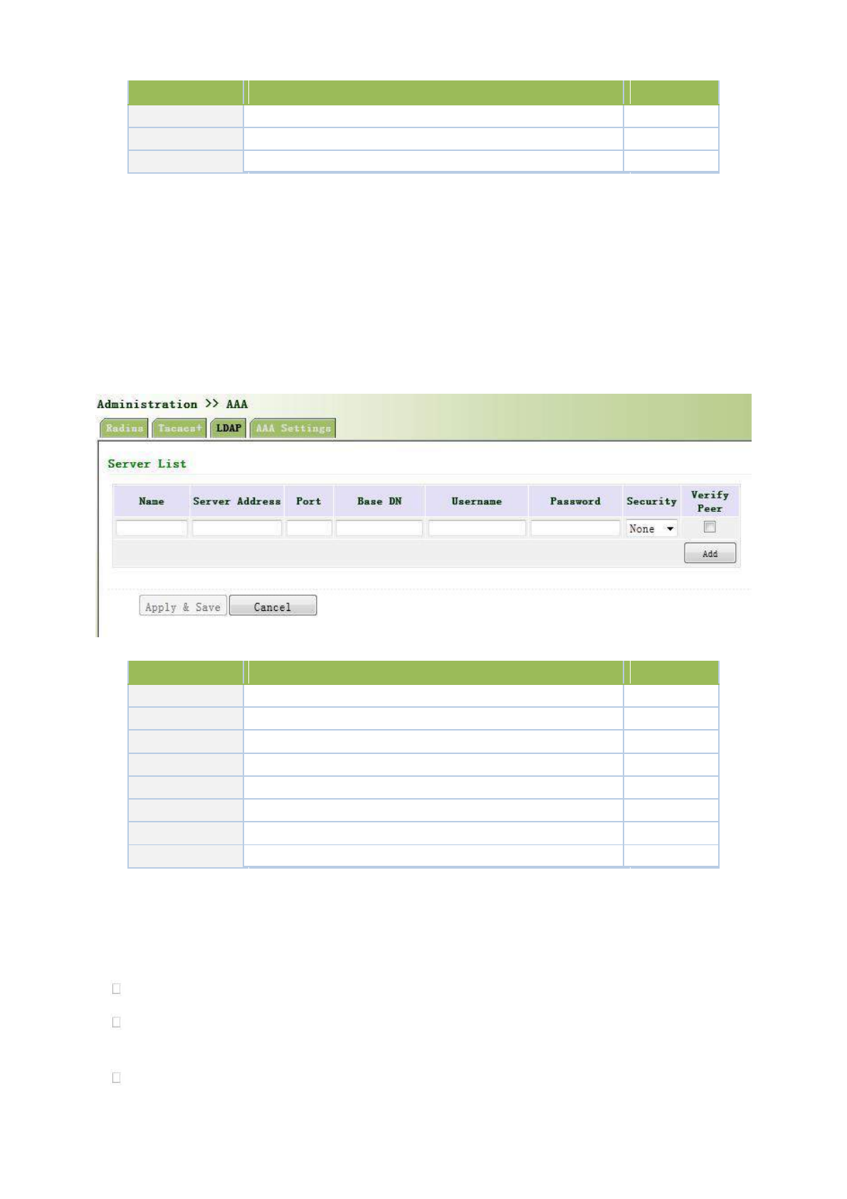
Parameters
Description
Default
Server Address
Server address (domain name / IP)
None
Port
Consistent with the server port
49
Key
Consistent with the server authentication key
None
3.2.4.3 LDAP
One of the great advantages of LDAP is rapid response to users’ searching request. For instance, user’s
authentication which may general a large amount of information sent as the same time. If database is adopted for
this purpose, since it is divided into many tables, each time to meet such a simple requirement, the whole database
has to be searched, integrated and filtered slowly and disadvantageously. LDAP, simple as a table, only requires
username and command and something else. Authentication is met from efficiency and structure.
From the left navigation panel, select Administration << AAA, then enter “LDAP” page, as shown below.
Page description is shown below:
Parameters
Description
Default
Name
Define server name
None
Server Address
Server address (domain name / IP)
None
Port
Consistent with the server port
None
Base DN
The top of LDAPdirectory tree
None
Username
Username accessing the server
None
Password
Password accessing the server
None
Security
Encryption mod: None,SSL,StartTLS
None
Verify Peer
Verify Peer
Unopened
3.2.4.4 AAA Settings
AAA supports following authentication ways:
None: with great confidence to users, legal check omitted, generally not recommended.
Local: Have user’s information stored on NAS. Advantages: rapidness, cost reduction. Disadvantages:
storage capacity limited by hardware.
Remote: Have user’s information stored on authentication server. Radius, Tacacs+ and LDAP supported
for remote authentication.
31
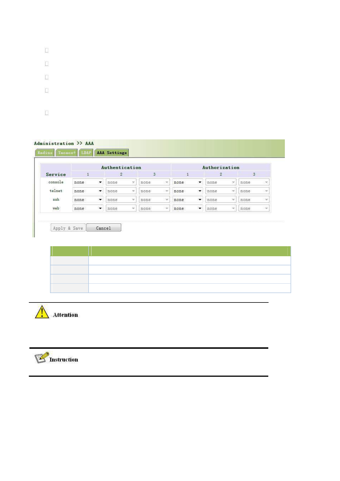
AAA supports following authorization ways:
None: authorization rejected.
Local: authorization based on relevant attributions configured by NAS for local user’s account.
Tacacs+: authorization done by Tacacs+ Server.
Radius Authentication Based: authentication bonded with authorization, authorization only by Radius
not allowed.
LDAP Authorization.
From the left navigation panel, select Administration << AAA, then enter “AAA Setting” page, as shown
below.
Page description is shown below:
Key Items
Description
radius
Authentication and Authorization Server
tacacs+
Authentication and Authorization Server
ldap
Authentication and Authorization Server
local
The local username and password
Authentication 1 should be set consistently with Authorization 1; Authentication 2 should be set
consistently with Authorization 2; Authentication 3 should be set consistently with
Authorization 3.
When configure radius, Tacas+, local at the same time, priority order follow:1 >2 >3.
3.2.5 Configuration Management
Here you can back up the configuration parameters, import the desired parameters configuration backup and
restore the factory settings of the router.
From the left navigation panel, select Administration << Config Management, then enter “Config
32
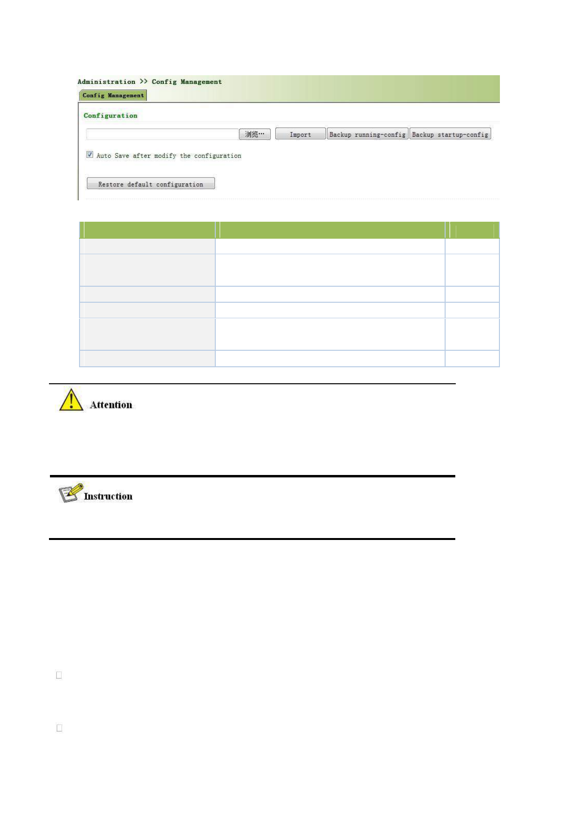
Management” page, as shown below.
Page description is shown below:
Parameters
Description
Default
Browse
Choose the configuration file
None
Import
Import configuration file to router startup-config
None
Backup running-config
Backup running-config file to host.
None
Backup startup-config
Backup startup-config file to host.
None
Automatically save modified
Decide whether to automatically save configuration
On
configuration
after modify the configuration.
Restore Default Configuration
Restore factory configuration
None
When import the configuration, the system will filter incorrect configuration files, and save the
correct configuration files, when system restarts, it will orderly execute theses configuration files.
If the configuration files didn’t be arranged according to effective order, the system won’t enter
the desired state.
In order not to affect current system running, when performing the import configuration and
restore the default configuration, need to reboot the router new configuration will take effect.
3.2.6 SNMP
Definition
SNMP, or Simple Network Management Protocol, is a standard network management protocol widely used
in TCP/IP networks and provides a method of managing the device through the running the central computer of
network management software. Features of SNMP:
Simplicity: SNMP adopts polling mechanism, provides the most basic sets of features and could be used in
small-scale, rapid, low cost environments. SNMP, with UDP message as the carrier, is supported by a great
majority of devices.
Powerfulness: objective of SNMP is to ensure the transmission of management information between any two
points so as to facilitate administrator’s retrieval of information on any node on network and modification and
33
troubleshooting.
Benefits
Network administrators could make use of SNMP to accomplish the information query, modification,
troubleshooting and other jobs on any node on network to achieve higher efficiency.
Shielding of physical differences between devices. SNMP only provides the most basic sets of features for
mutual independence between administration and the physical properties, network types of devices under
administration; therefore, it could realize the uniform management of different devices at a lower cost.
Simple design, lower cost. Simplicity is stressed on addition of software/hardware, types and formats of
message on devices so as to minimize the influence and cost on devices caused by running SNMP.
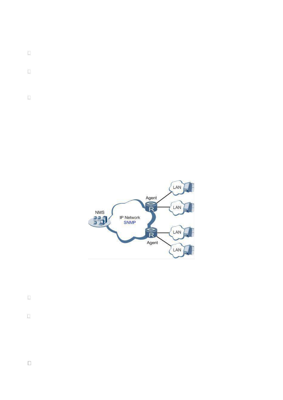
Application: management of device is achieved through SNMP
Administrator is required to carry out configuration and management of all devices in the same network, which are
scattered, making onsite device configuration impracticable. Moreover, in case that those network devices are supplied
from different sources and each source has its independent management interfaces (for example, different command
lines), the workload of batch configuration of network devices will be considerable. Therefore, under such
circumstances, traditional manual ways will result in lower efficiency at higher cost. At that time, network administrator
would make use of SNMP to carry out remote management and configuration of attached devices and achieve real-time
monitoring. Following is a figure showing how to manage devices through SNMP:
To configure SNMP in networking, NMS, a management program of SNMP, shall be configured at the Manager.
Meanwhile, Agent shall be configured as well.
Through SNMP:
NMS could collect status information of devices whenever and wherever and achieve remote control of
devices under management through Agent.
Agent could timely send current status information to NMS report device. In case of any problem, NMS will
be notified immediately.
SNMP(Simple Network Management Protocol)is an application-layer communication
protocol, through SNMP, network administrators can manage network performance, find and
solve network problems, and plan network growth.
SNMP includes NMS and Agent:
NMS(Network Management Station) is a station which runs client procedure.
34

Agent is service software which is running in device.
The purpose of NMS and Agent is as followed:
NMS can send getRequest, getNextRequest, setRequest packets to Agent, when the Agent
receive these packets, it will execute read or write operations according to the type of packet
and create Response packet back to NMS.
When device happens to status change (for example port plug), Agent will send Trap packet
and report all the events to NMS.
3.2.6.1 SNMP Basic Setting
SNMP agent of device supports SNMPv1, SNMPv2 and SNMPv3 at present.
SNMPv1 and SNMPv2 adopt community name to authenticate.
SNMPv3 adopt username and password to authenticate.
From the left navigation panel, select Administration << SNMP, then enter “SNMP” page, as
shown below.
Page description is shown below:
Parameters
Description
Default
Enable
Enable/Disable SNMP
Disable
SNMP Version
Support SNMP v1/v2c/v3
v2c
Contact
Fill Contact Information
Welotec
Information
Location
Fill Location Information
Laer, Germany
Information
Community Management
Community Name
User define Community Name
Publi and private
Access Limit
Select access limit
Read-only
MIB View
Select MIB View
defaultView
When choosing SNMPv3 version, the corresponding Use and User Group should be configured. The
configuration page is shown below.
Page description is shown below:
Parameters
Description
Default
35
Groupname
User define, length:1-32 charaters
None
Security
Includes NoAuth/NoPriv, Auth/NoPriv, Auth/priv
NoAuth/NoPriv
Level
Read-only
Only support defaultView at present
defaultView
View
Read-write
Only support defaultView at present
defaultView
View
Inform View
Only support defaultView at present
defaultView
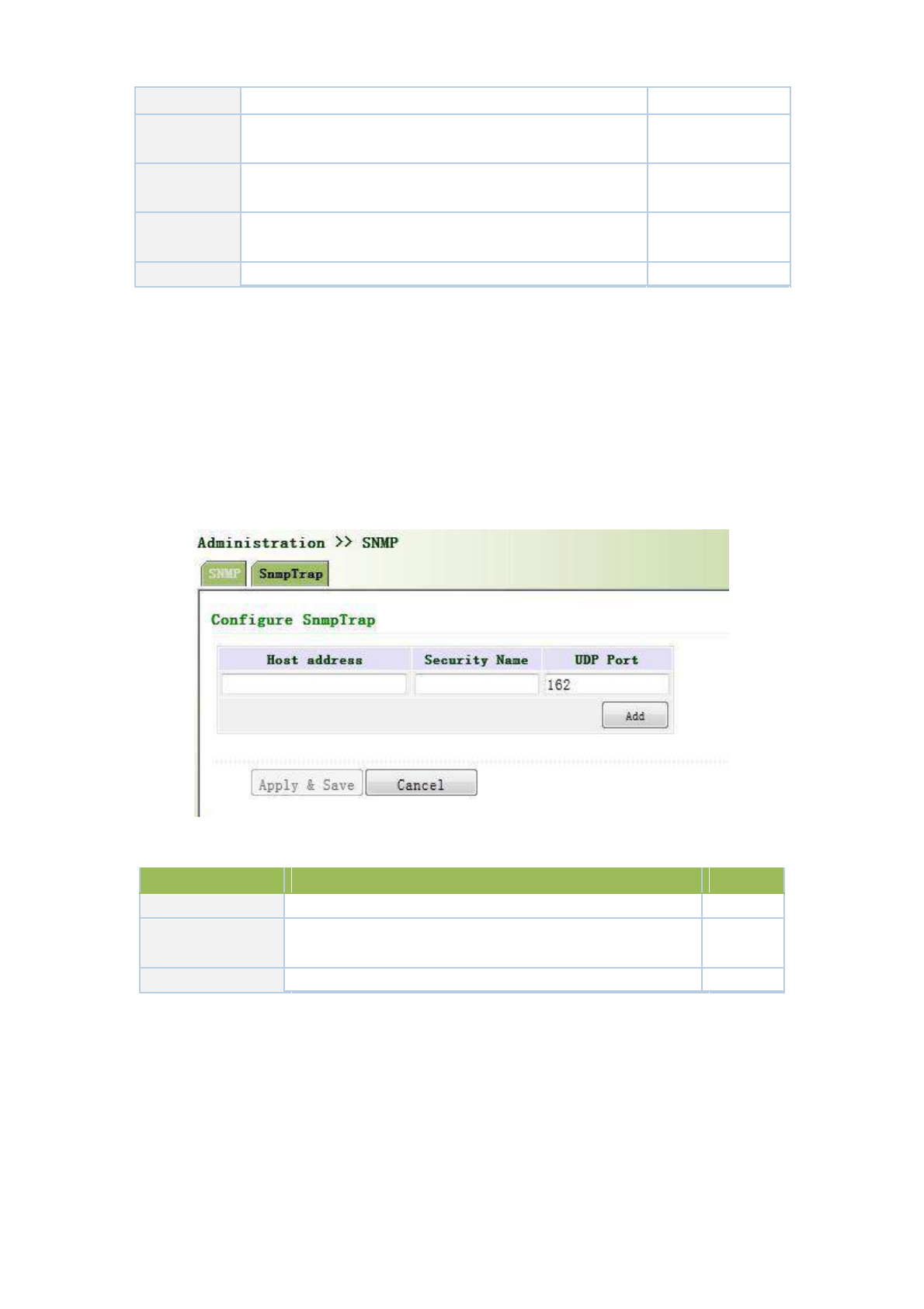
3.2.6.2 SnmpTrap Setting
SNMP trap: A certain port where devices under the management of SNMP will notify SNMP manager rather
than waiting for polling from SNMP manager. In NMS, Agents in managed devices could have all errors reported
to NMW at any time instead of waiting for polling from NMW after its reception of such errors which, as a matter
of fact, are the well-known SNMP traps.
From the left navigation panel, select Administration << SNMP, then enter “SnmpTrap”
page, as shown below.
Page description is shown below:
Parameters
Description
Default
Host Address
Fill in the NMS IP address
None
Securtiy Name
Fill in the groupname when use the SNMP v1/v2c; Fill in the
None
username when use the SNMP v3. Length :1-32 characters
UDP Port
Fill in UDP port, the default port range is 1-65535
162
3.2.7 Alarm
Alarm function is a way which is provided for users to get exceptions of device, which can make
the users find and solve exceptions as soon as possible. When abnormality happened, device will
send alarm. User can choose many kinds of exceptions which system defined and choose
appropriate notice way to get these exceptions. All the exceptions should be recorded in alarm log
so that user troubleshoot problem.
36

According to the type of alarm, it can be divided system alarm and port alarm.
System Alarm: It produces because of system or environment happened to some exception, divided
into temperature, hot start, cold start, power failure, power recovery, insufficient memory.
Port Alarm: It produces because of the network interface is up or down, divided into LINK-UP,
LINK-DOWN.
Alarm status divided into raise, confirm, clear, When alarm occurs , it is in the state of "raise", if the
user thinks this alarm is not great importance or the exception has been solved , he can directly set it
to "clear" state; if the user is temporarily unable to resolve this anomaly, he can set it to "confirm"
state, when the exceptions had been eliminated , it was set to "clear".
Alarm level can be divided:
EMERG:Device occurs some faults, it could lead to the system restart.
CRIT:Device occurs some faults which are unrecoverable.
WARN:Device occurs some faults which could affect system function.
NOTICE:Device occurs some faults which could affect system properties.
INFO:Device occurs some normal events.
On the “Alarm Status” page, you can view all the alarms since system was power on.
On the “Alarm Input” page, you can define alarm types which you concern.
On the “Alarm Output” page, you can set the way of alarm notice, including relay and Email, log
record is a default output way.
On the “Alarm Map” page, you can map the alarm type which you concern to one or more alarm
notice way.
3.2.7.1 Alarm Status
From the left navigation panel, select Administration>> Alarm, then enter “Alarm State”
page, as shown below. Through this page, you can check all the alrms since the router is powered.
Click <Clear All Alarms> to set all the alarm to “clear” state.
Click<Confirm All Alarms> to set all the alarm to “cconfirm” state.
Click<Reload> to reload all the alarms.
Page description is shown below:
Parameters
Description
Default
ID
Alarm index
None
Status
Current alarm status
ALL
Level
Current alarm level
None
Date
Date of alarm occurs
None
37
System Time
The time from system startup to alarm produce (s)
None
Content
Alarm description
None
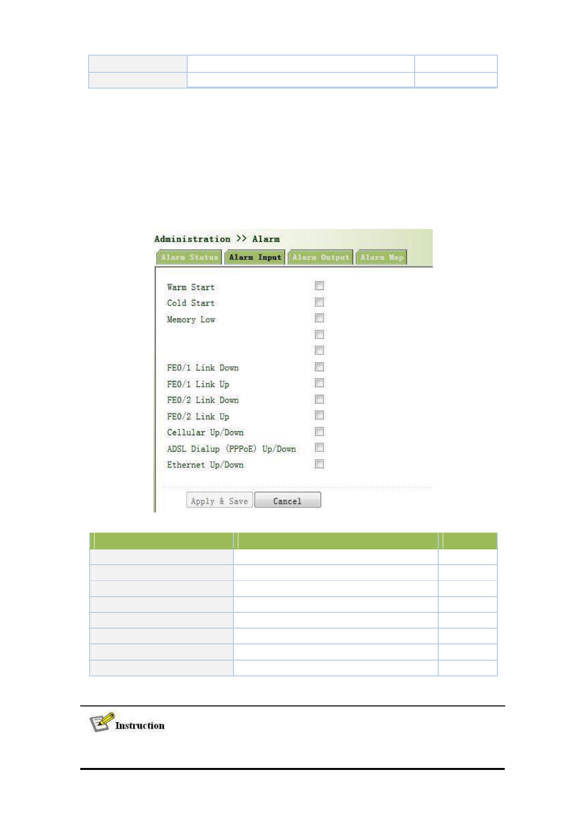
3.2.7.2 Alarm Input
Here user could select alarm types including system alarm and port alarm. One or more than one types could
be selected.
From the left navigation panel, select Administration >>Alarm, then enter “Alarm Input”
page, as shown below.
Page description is shown below:
Parameters
Description
Default
Warm Start
On/Off Warm Start alarm
Off
Cold Start
On/Off Cold Start alarm
Off
Memory Low
On/Off Memory Low alarm
Off
Fastethernet LINK-UP
On/Off LINK-UP alarm
Off
Fastethernet LINK-DOWN
On/Off LINK-Down alarm
Off
Cellular Up/Down
On/Off Cellular Up/Down alarm
Off
PPPoE Up/Down
On/Off PPPoE Up/Down alarm
Off
Ethernet Up/Down
On/Off Ethernet Up/Down alarm
Off
For TK8X5L with industrial interface, there are two more items on Alarm Input Page: Digital
Input High and Digital Input Low.
38
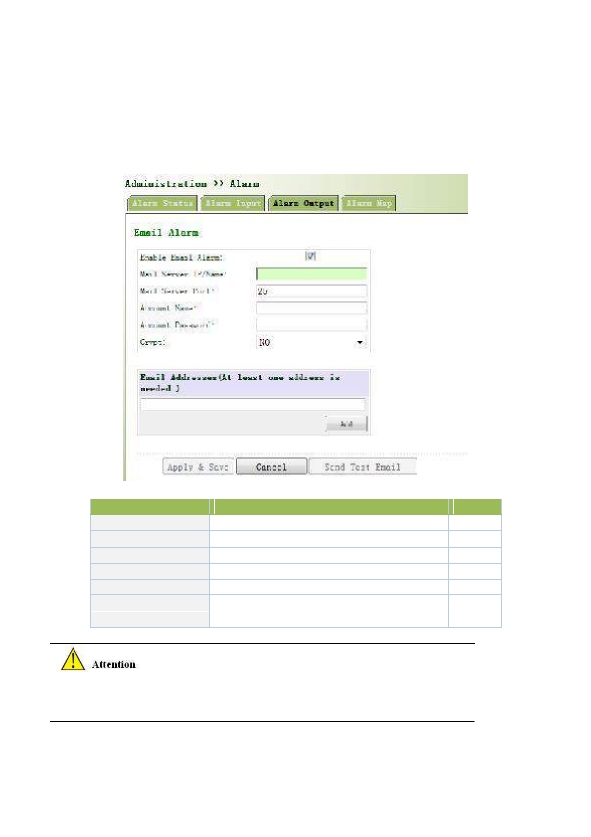
3.2.7.3 Alarm Output
When an alarm happens, the system configured with this function will send the alarm content
to intended email address from the mail address where an alarm email is sent in a form of email.
Generally this function is not configured.
From the left navigation panel, select Administration >>Alarm, then enter “Alarm Output”
page, as shown below.
Page description is shown below:
Parameters
Description
Default
Enable Email Alarm
On/Off Email Alarm
Off
Mail Server IP/Name
Set IP address of Mail Server that send alarm emails
None
Mail Server Port
Set Port of Mail Server that send alarm emails
25
Account Name
Set Email address from which alarm emails are sent
None
Account Password
Set Email password
None
Crypt
Set the crypt method
None
Email Addresses
Destination address of receiving alarm email (1-10)
None
When the email parameters had been configured, you should click the “send test email” button so
that ensure the configuration is correct. If the test email failed, it may the network configuration or
mailbox configuration is not correct.
3.2.7.4 Alarm Map
39
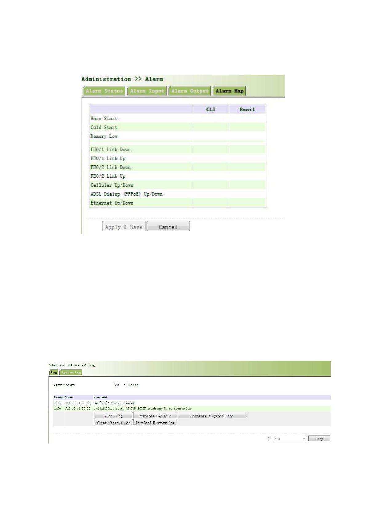
Alarm Map consists of two mapping ways: CLI (console interface)and Email. In case of latter one is selected,
and then alarm output shall be activated with an email address well configured.
From the left navigation panel, select Administration >>Alarm, then enter “Alarm Map”
page, as shown below.
3.2.8 System Log
System Log includes massive information about network and devices, including operating status,
configuration changes and so on, serving as an important way for network administrator to monitor and control
the operation of network and devices. System Log could provide information to help network administrator to find
network problems or safety hazard so as to take more targeted measures.
3.2.8.1 Log
From the left navigation panel, select Administration >>Log, then enter “System Log” page,
as shown below.
3.2.8.2 System Log Settings
40
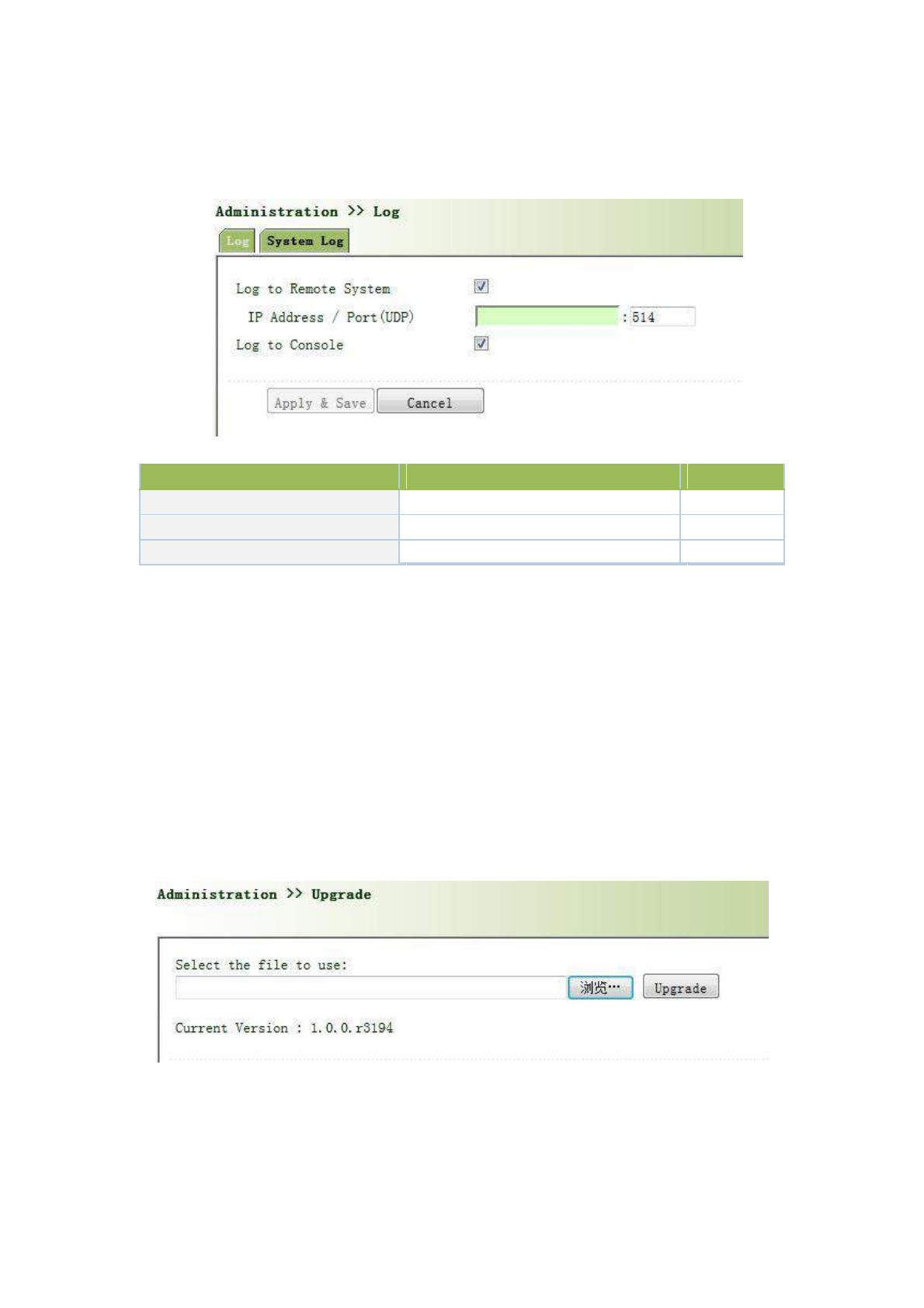
On “System Log Settings”, remote log server could be set. Router will have all system logs sent to remote
log server depending on remote log software (for example: Kiwi Syslog Daemon).
From navigation panel, select Administration >>Log, then enter “System Log” page, as
shown below.
Page description is shown below:
Parameters
Description
Default
Log to Remote System
Open/close remote log function
Close
IP Address/ Port(UDP)
Set remote server’s IP address/Port
514
Log to Console
Open/close console log function
Open
3.2.8.3 Kiwi Syslog Daemon
Kiwi Syslog Daemon is a kind of free log server software used in Windows, which could receive, record and
display logs formed when powering on the host of syslog (for example, router, exchange board, Unix host). After
downloading and installation of Kiwi Syslog Daemon, configure necessary parameters on
“File<<Setup<<Input<<UDP”.
3.2.9 System Upgrading
From navigation panel, select Administration >>Upgrade, then enter “Upgrade” page, as
shown below.
Click < Browse > to upgrade documents and then click <Upgrade> to start. The whole process takes about
1min, upon the completion of which, restart the router and new firmware takes effect.
41
Software upgrade takes time, during which, please do no carry out any operation on Web,
otherwise, interruption may take place.
Upgrade consists of two stages: first stage: read-in of upgrade document into backup firmware
zone, as described in Section of System Upgrade; second stage: copy of documents in backup
firmware zone into main firmware zone, which may be executed in system reboot.
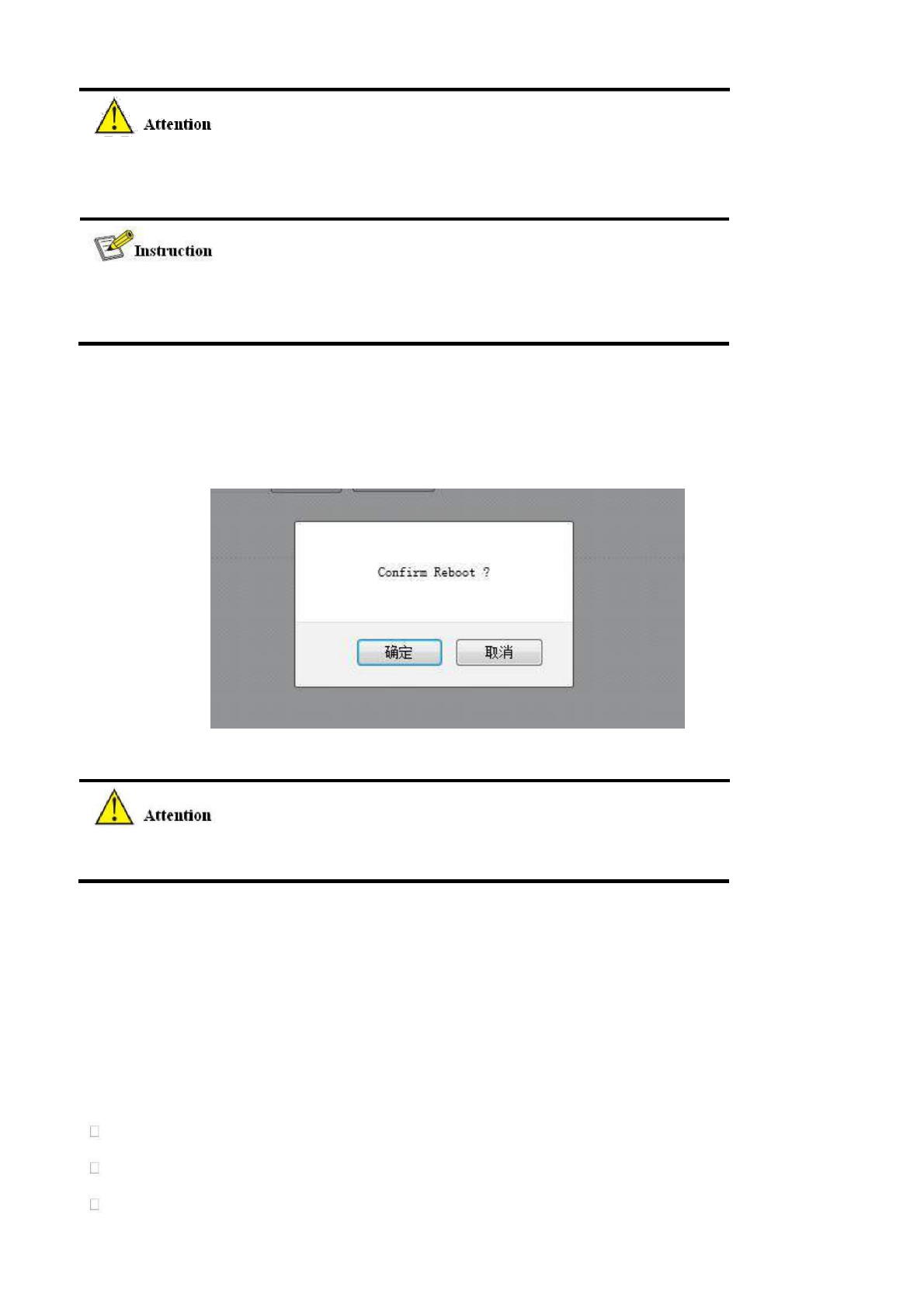
3.2.10 Reboot
From navigation panel, select Administration >>Reboot, then enter “Reboot” page, as shown
below. Click <Yes> to reboot the system.
Please save the configurations before reboot, otherwise the configurations that are
not saved will be lost after reboot.
3.3 Network
3.3.1 Ethernet Port
Ethernet Port supports three connection modes:
Automatic: configuration interface as DHCP Client and IP address obtained by DHCP.
Manual: manually configure IP address and subnet mask for interface.
PPPoE: configuration interface as PPPoE Client. PPPoE, the short form of Point-to-Point Protocol over
42
Ethernet, achieves networking of a large number of hosts through Ethernet, connects with internet through a
remote access device and carries out control and charging of each connected host. High performance and
favorable price are the key factors for PPPoE’s extensive applications in community networking construction
and so on.
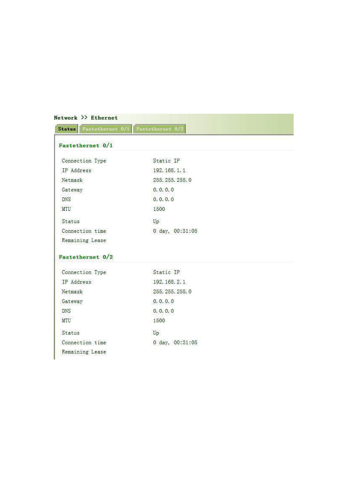
3.3.1.1 Status
From navigation panel, select Network >>Ethernet, then enter “Status” page, as shown below.
3.3.1.2 Ethernet Port
The connection of Ethernet port here is manual mode, namely, manually configuring an IP
address and subnet mask.
The configuration of the two Ethernet ports is the same. Take Ethernet 0/1 as an example.
From navigation panel, select Network >>Ethernet, then enter “Fastethernet 0/1” page, as
shown below.
43
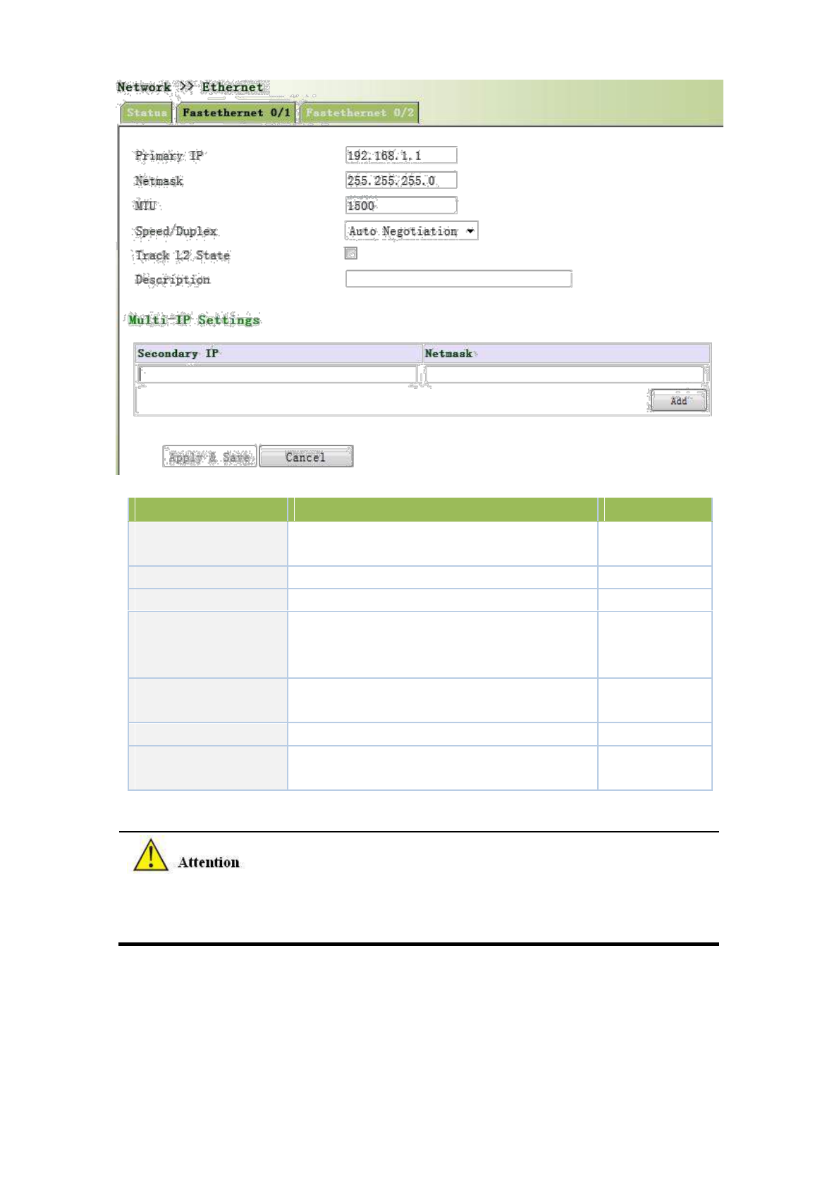
Page description is shown below:
Parameters
Description
Default
Primary IP
IP address could be
configured
or
changed
192.168.1.1
according to demand
Subnet Mask
Autogeneration
255.255.255.0
MTU
Maximal transmission unit, byte as the unit
1500
Five options:
Auto
Negotiation,
100M
Full
Auto
Speed/Duplex
Duplex, 100M Half -Duplex, 10M Full Duplex
Negotiation
and 10M Half-Duplex
Track L2 State
On: Port status after disconnection: Down
Off
Off: Port status after disconnection: UP
Description
User defines the description
N/A
Multi-IP Settings
In addition to
the primary IP, user
could
set
N/A
Secondary IP addresses, 10 maximal.
In factory default state, DNS of PC connected at the lower end of F0/1 can not be applied with the
original port IP of F0/1, otherwise, public domain can not be visited. But, visiting public domain
can be realized by starting DHCP server or setting other DNS server.
3.3.1.3 Bridge Interface
Click navigation panel “Network>>Ethernet” menu, enter “ethernet 0/1” interface, as shown below:
44
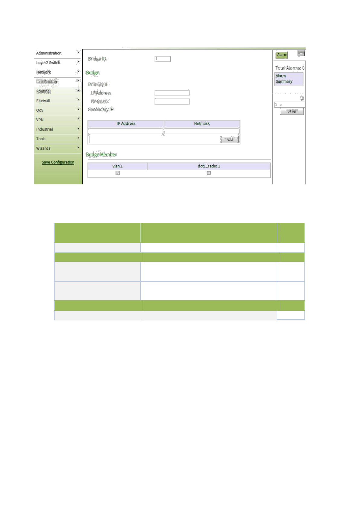
Page description is shown below:
Parameter Name
Description
Default
Value
Bridge ID
Bridge ID can only be matched with 1
No
Bridge Interface
IP Address of Main Address
Main IP address and subnet mask can be matched or
No
and Subnet Mask
modified according to the demand
IP Address of Slave Address
Users can be matched with IP address and subnet
No
and Subnet Mask
mask except for main IP
Bridge Member
Click through the name of interface starting bridge interface
No
3.3.2 Dialup Port
SIM card dial out through dial access to achieve the wireless network connection function of router.
TK8X5L supports dial SIM card for backup. When primary SIM card breaks down or balance insufficiency,
which results in network disconnection, rapid switching to backup SIM card is available, which will assume the
task of network connection so as to improve the reliability of network connection.
Dial access supports three ways of connection: Always Online, Dial on Demand and Manual Dial.
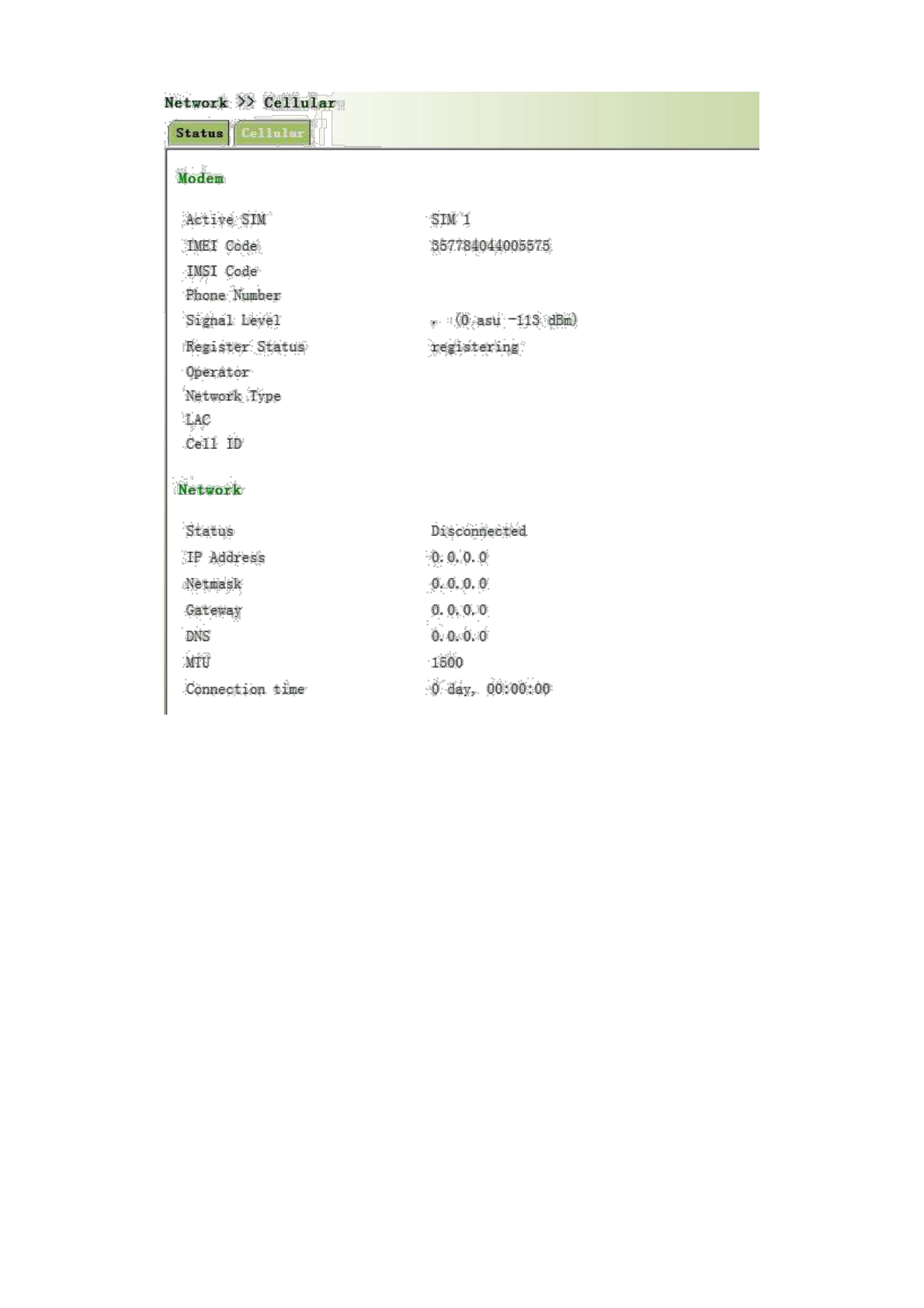
3.3.2.1 Status
From navigation panel, select Network >>Cellular, then enter “Status” page, as shown below.
45
3.3.2.2 Dialup Port
In “Cellular”page, wireless dialup can be configured.
From navigation panel, select Network >>Cellular, then enter “Cellular” page, as shown below.
46
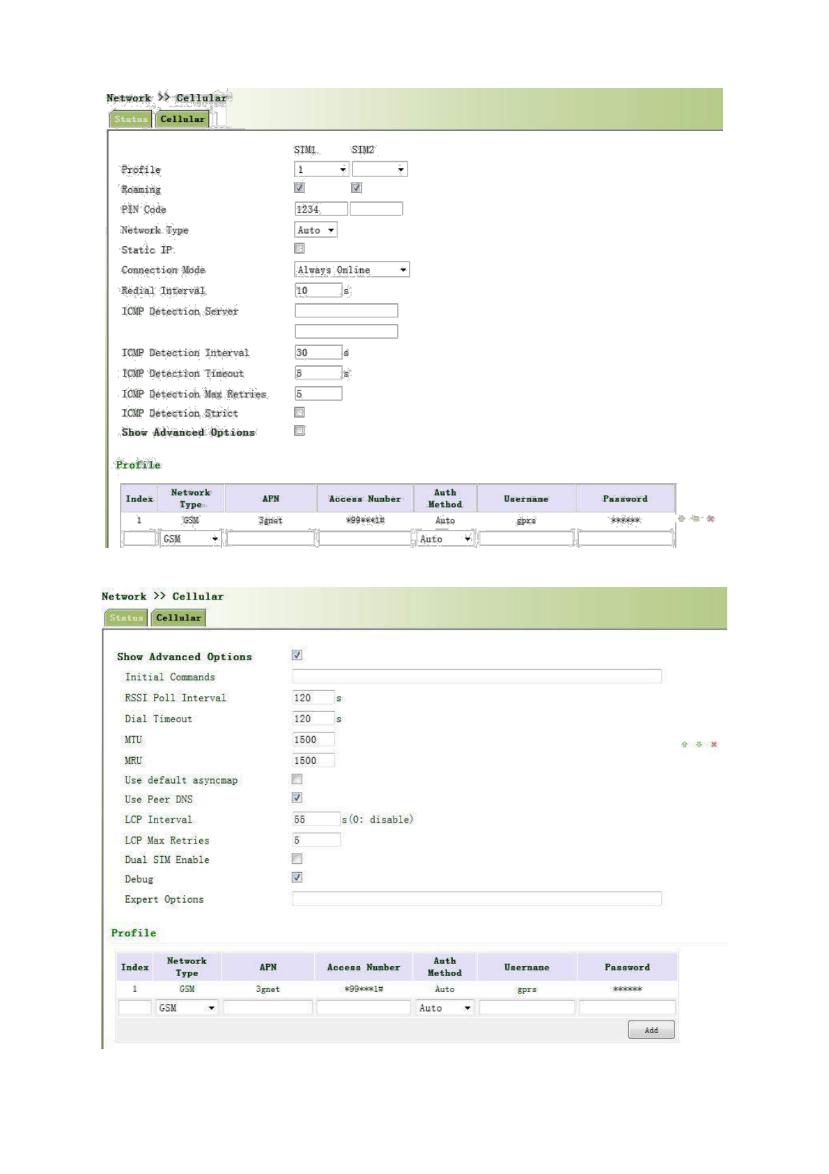
Advanced Options are shown below:
Page description is shown below:
47

Parameters
Description
Default
Profile
Dial-up strategy
1
Roaming
Enable/Disable roaming
Enable
PIN Code
SIM card PIN code
None
Network Type
Three options:Auto, 2G, and 3G
Auto
Static IP
Enable Static IP if your SIM card can get static IP
Disable
address
Connection Mode
Optional Always Online,connect on demand
Always
Online
Redial Interval
the time interval between first dail fials can redial
10s
ICMP Detection Server
Set ICMP Detection Server
None
ICMP Detection Interval
Set ICMP Detection Interval
30s
ICMP Detection Timeout
Set ICMP Detection Timeout
5s
ICMPDetection
Max
Set the max number of retries if ICMP failed
5
Retries
No matter whether TK8X5L have some data
receive
ICMP Detection Strict
or transmit, TK8X5L always send the ICMP probe
Disable
packet
Profile
Network Type
Choose mobile network type
GSM
APN parameters provided by Local ISP, you can set
APN
TWO different group of dialup parameters
3gnet
(APN/Username/Password) and set one as backup
Access Number
APN parameters provided by Local ISP
*99***1#
Username
APN parameters provided by Local ISP
gprs
Password
APN parameters provided by Local ISP
******
Advanced Options
Initial Commands
Used for advanced parameters
None
RSSI Poll interval
Set the signal query interval
120s
Dial Timeout
Dial timeout, the system will redial
120s
MTU
Set max transmit unit,In bytes
1500
MRU
Set max receive unit,In bytes
1500
Use default asyncmap
Enable default asyncmap, PPP advanced option
Disable
Use Peer DNS
Receivingmobile operatorsassigned DNS
Enable
LLCP Interval
LCP Detection Interval
55s
LCP Max Retries
et the max retries if link detection failed
5
Debug
System canprint a moredetailed log
Enable
Expert Option
Provide extra PPP parameters, normally user needn’t
None
set this.
Dual SIM Cards
Dual SIM Enable
Enable dual SIM card mode
Disable
Main SIM
The dual SIM card work mode
SIM1
Max Number of Dial
Reach the maxnumber, SIM cardwillbeswitched
5
Min Connected Time
Set min conected time
0s
CSQ Threshold
Set signal strength threshold, the signal strength
0
48
under this threshold, router will redetect the signal
strength
CSQ Detect Interval
Set signal strength detect interval
0
CSQ Detect Retries
Set signal strength detect retries
0
Frombeginningto
switch
to
Backup SIM Timeout
thebackupcardcounting,
exceeds the
tiemout,
0
router will switch to the primarycard
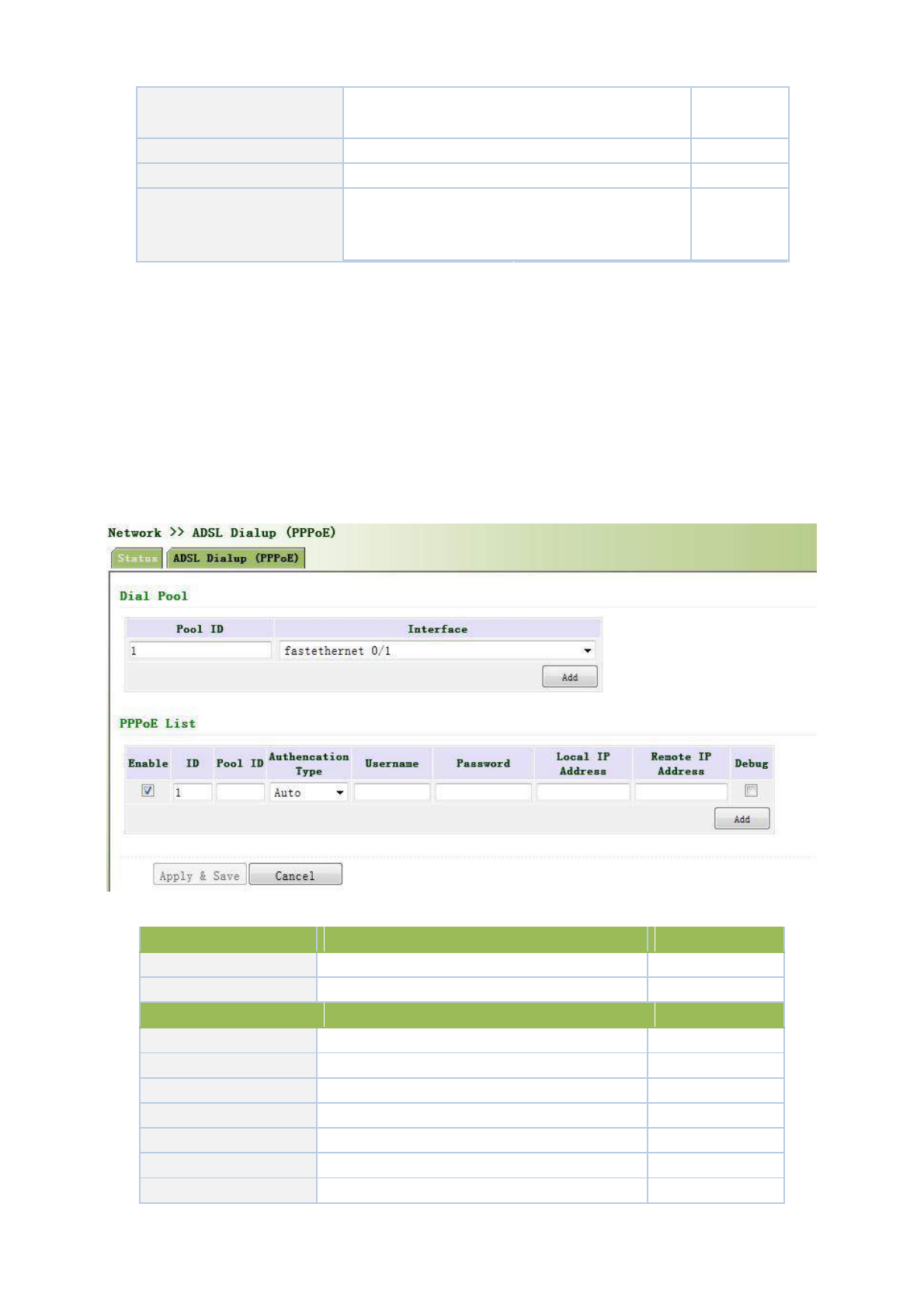
3.3.3 PPPoE
PPPoE is a Point-to-Point Protocol over Ethernet. User has to install a PPPoE Client on the basis of original
connection way. Through PPPoE, remote access devices could achieve the control and charging of each accessed
user.
Connection mode at Ethernet port is PPPoE, namely, configuration interface as PPPoE Client.
From navigation panel, select Network >>ADSL Dialup, then enter “PPPoE” page, as shown
below.
Page description is shown below:
Parameters
Description
Default
Pool ID
User define, easy to memorize and manage
None
Interface
Fastethernet0/1, Fastethernet0/2
Fastethernet0/1
PPPoE List
ID
User define, easy to memorize and manage
1
Pool ID
Same with the dialup pool
None
Authentication Type
Auto, PAP, CHAP
Auto
User Name
Operators provide the relevant parameters
None
Password
Operators provide the relevant parameters
None
Local IP Address
Set the IP address assigned for Ethernet interface
None
Remote IP Address
Set the IP of remote device
None
49
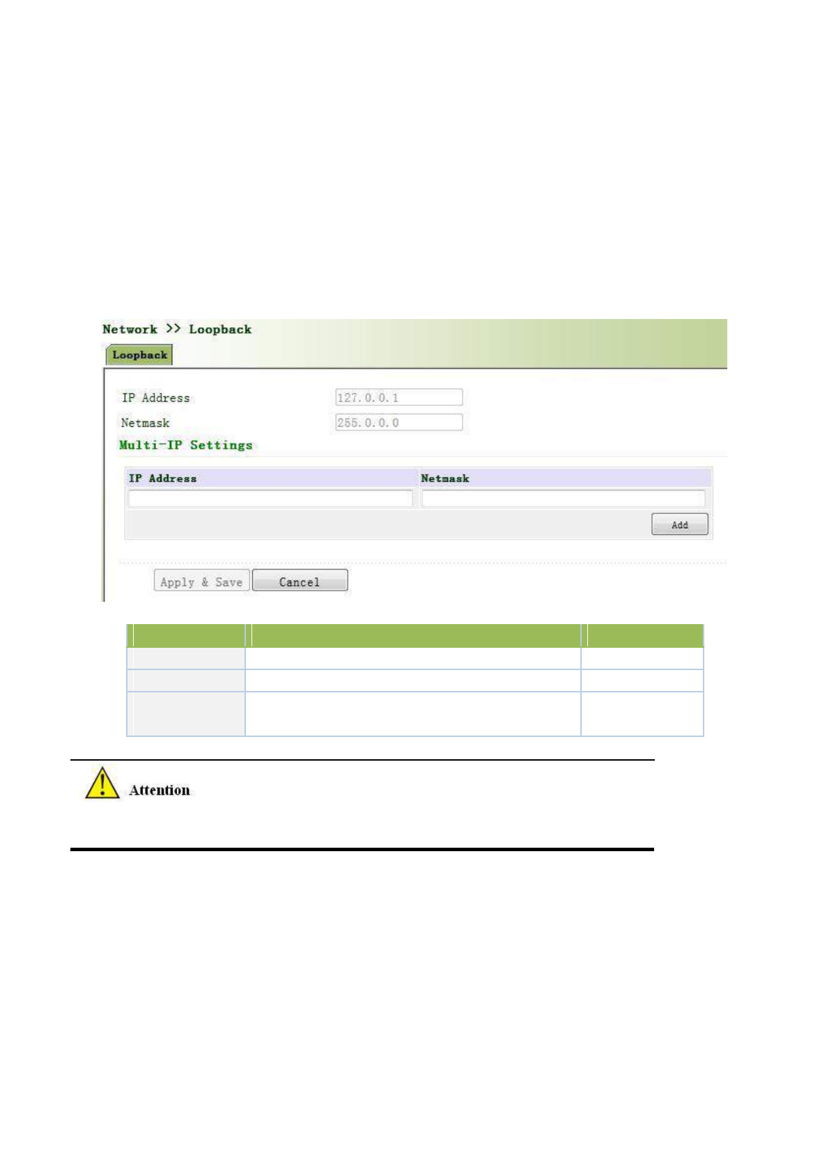
3.3.4 Loopback
Loopback Interface is to take place of router’s ID since as long as an active interface is used, when it turns to
DOWN, ID of router has to be selected again, resulting to long convergence time of OSPF. Therefore, generally
Loopback Interface is recommended as the ID of router.
Loopback Interface is a logic and virtual interface. As default, a router has no Loopback Interface which can
be created for a number. Those interfaces are the same as physical interfaces on router: addressing information
allocated, including their network number in router upgrade and even IP connection could be terminated on them.
From navigation panel, select Network >>Loopback, then enter “Loopback” page, as shown
below.
Page description is shown below:
Parameters
Description
Default
IP Address
Users can not change
127.0.0.1
Netmask
Users can not change
255.0.0.0
Multi-IP Settings
Apart from above IP, user can configure other IP
N/A
address
Since loopback interface takes up one IP address, subnet mask is suggested to
be 255.255.255.255 for the purpose of saving resources.
3.3.5 DHCP service
Along with the continuous expansion of network size and complication of network, number of computers
often exceeds distributable IP addresses. Meanwhile, in pace with the extensive application of portable devices
and wireless network, position of computer changes frequently, resulting to the frequent upgrade of IP address,
leading to a more and more complicated network configuration. DHCP (Dynamic Host Configuration Protocol)is
a product for such demands.
DHCP adopts Client/Server communication mode. Client sends configuration request to Server which feeds back
corresponding configuration information, including distributed IP address to the Client to achieve the dynamic
50
configuration of IP address and other information.
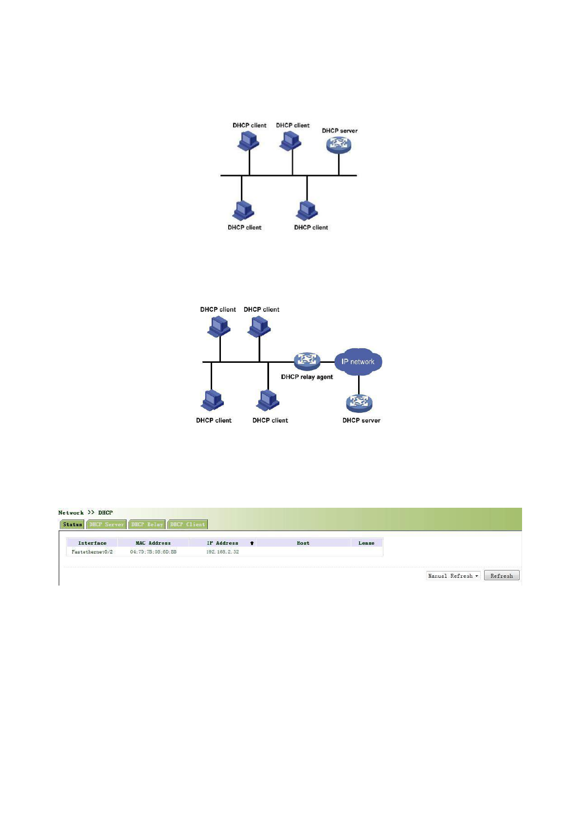
In typical applications of DHCP, generally one DHCP Server and a number of Clients (PC and Portable
Devices) are included, as the following figure shows:
When DHCP Client and DHCP Server are in different physical network segment, Client could communicate
with Server through DHCP Relay to obtain IP address and other configuration information, as the following figure
shows:
3.3.5.1 Status
From navigation panel, select Network >>DHCP, then enter “Status” page, as shown below.
3.3.5.2 DHCP Server
The duty of DHCP Server is to distribute IP address when Workstation logs on and ensure each workstation
is supplied with different IP address. DHCP Server has simplified some network management tasks requiring
manual operations before to the largest extent.
From navigation panel, select Network >>DHCP, then enter “DHCP Server” page, as shown
below.
51
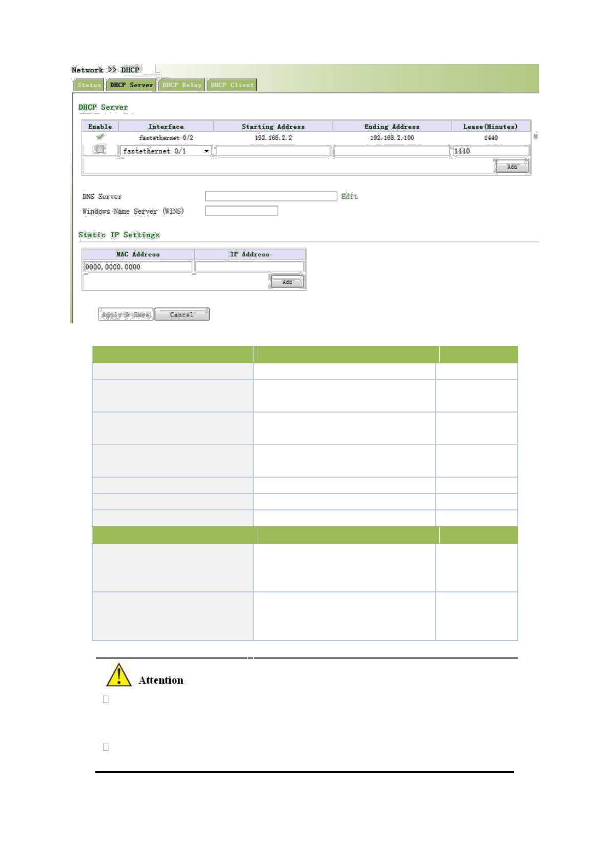
Page description is shown below:
Parameters
Description
Default
Enable
On/Off
Off
Interface
Fastethernet0/1and
Fastethernet0/2
Fastethernet0/1
available
Starting Address
Dynamical
distribution
of
starting
IP
N/A
address
Ending Address
Dynamical
distribution
of
ending
IP
N/A
address
Lease
Dynamical distribution of IP validity
1440
DNS Server
One or two, or None
N/A
WINS
Setup of WINS, generally left blank
N/A
Static IP Setup
Set up a static specified DHCP’s MAC
MAC Address
address (different from other MACs
0000.0000.0000
to avoid confliction)
Set up a static specified IP address
IP Address
(within the scope from start IP to end
N/A
IP)
If the host connected with router chooses to obtain IP address automatically, then such
service must be activated. Static IP setup could help a certain host to obtain specified IP
address.
TK8X5L F0/2 enable DHCP server by default; obtaining IP address automatically is
suggested.
52
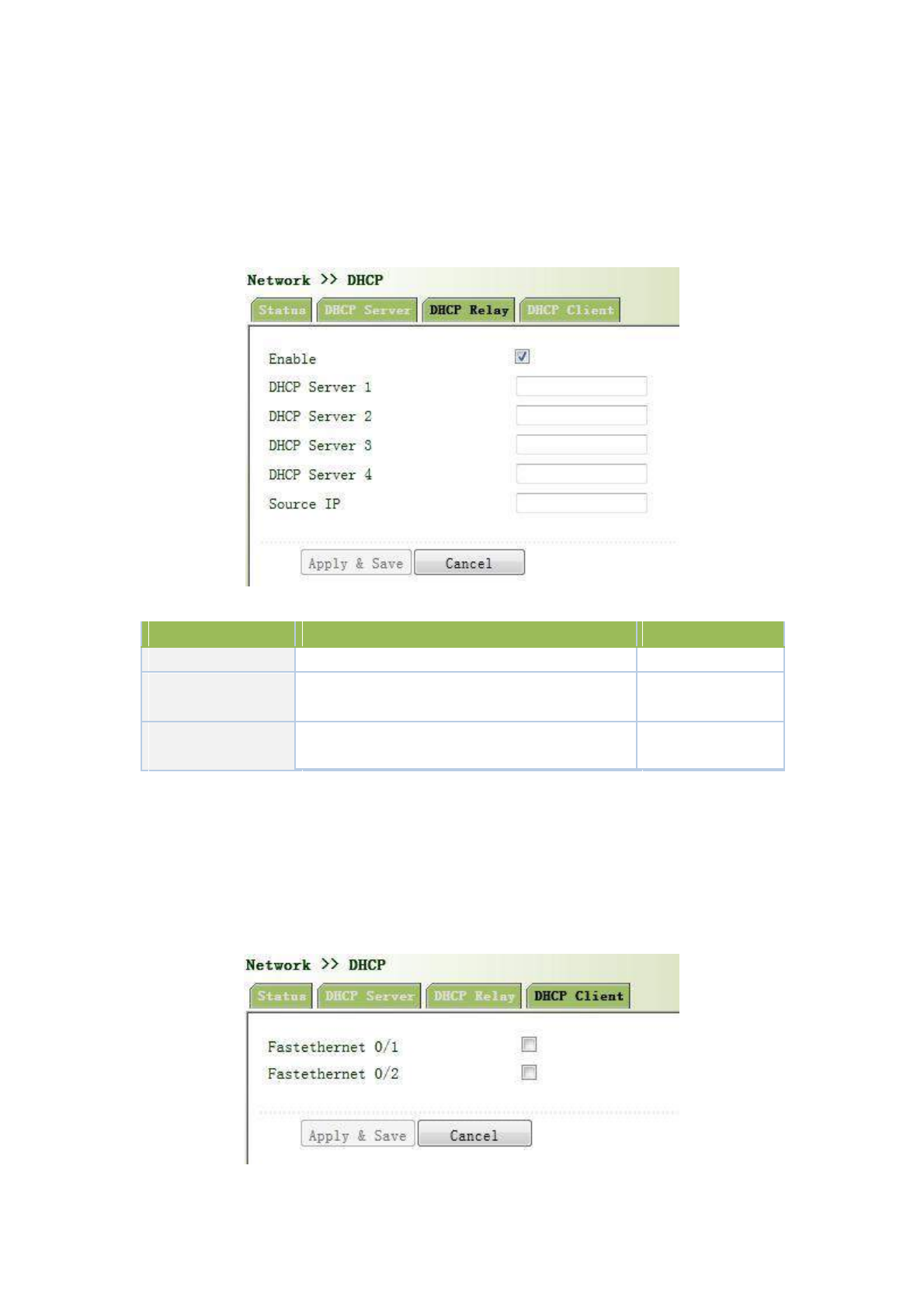
3.3.5.3 DHCP Relay
Generally, DHCP data packet is unable to be transmitted through router. That is to say, DHCP Server is
unable to provide DHCP services for two or more devices connected with a router remotely. Through DHCP relay,
DHCP requests and response data packet could go through many routers (Broadband Router).
From navigation panel, select Network >>DHCP, then enter “DHCP Relay” page, as shown
below.
Page description is shown below:
Parameters
Description
Default
Enable
On/Off
Off
DHCPSever
Set DHCP server; up to 4 servers can be
N/A
configured
Source address
Address of the interface connected to the DHCP
N/A
server
3.3.5.4 DHCP Client
DHCP Client obtains an IP address assigned by DHCP server after logging onto it. The IP
address is obtained through DHCP.
From navigation panel, select Network >>DHCP, then enter “DHCP Client” page, as shown
below.
53
3.3.6 DNS Services
DNA (Domain Name System) is a DDB used in TCP/IP application programs, providing switch between
domain name and IP address. Through DNS, user could directly use some meaningful domain name which could
be memorized easily and DNS Server in network could resolve the domain name into correct IP address.
The device supports to achieve following two functions through domain name service configuration:
DNS Server: for dynamic domain name resolution.
DNS relay: the device, as a DNS Agent, relays DNS request and response message between DNS Client and
DNS Server to carry out domain name resolution in lieu of DNS Client.
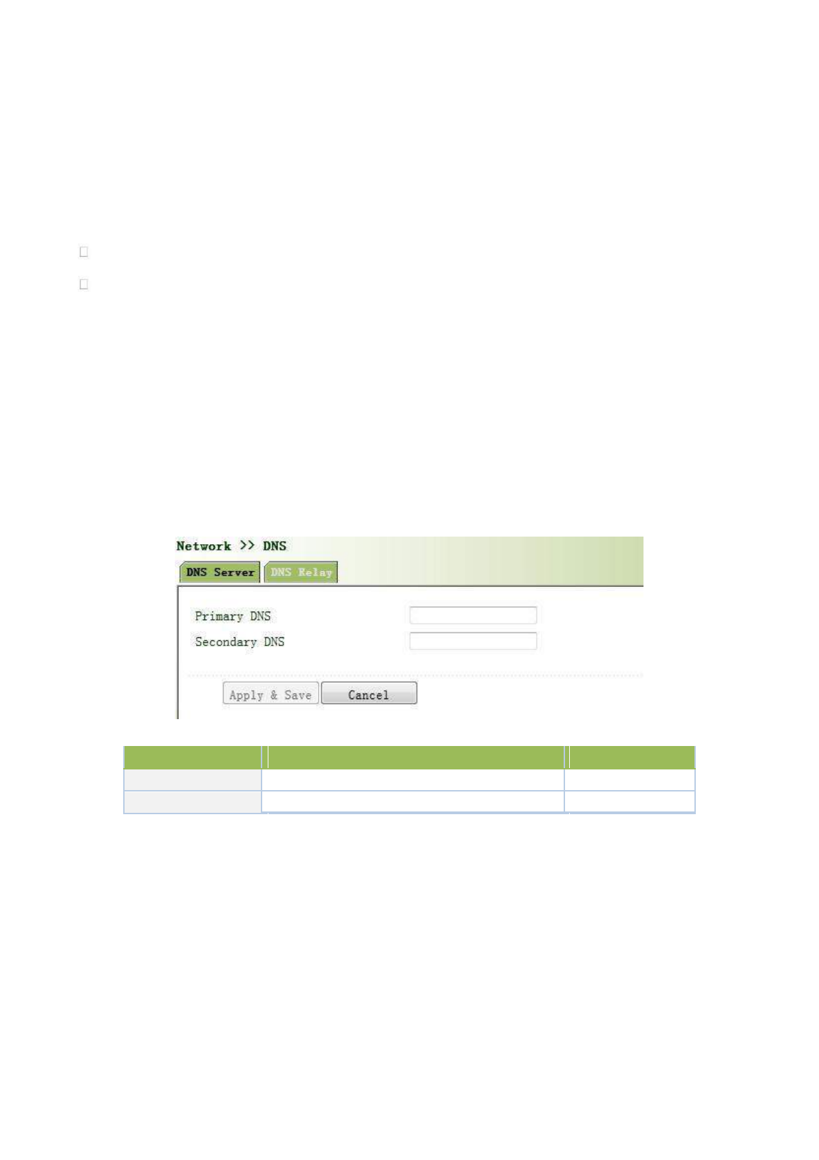
3.3.6.1 DNS Server
Domain Name Server: DNS stands for Domain Name System. It is a core service of the
Internet. As a distributed database that can let the domain names and IP addresses mapping to each
other, it allows people to more conveniently access to the Internet without the need to memorize the
IP string that can be directly read by the computer.
From navigation panel, select Network >>DNS, then enter “DNS Server” page, as shown below. In
manual setup of DNS Server, if it is blank, then dial to obtain DNS. Generally this item is required to be set when
WAN port uses static IP.
Page description is shown below:
Parameters
Description
Default
Primary DNS
User define Primary DNS address
N/A
Secondary DNS
User define Secondary DNS address
N/A
3.3.6.2 DNS Relay
DNS forwarding: DNS forwarding is open by default. You can set the specified [Domain Name
<=> IP Address] to let IP address match with the domain name, thus allowing access to the
appropriate IP through accessing to the domain name.
From navigation panel, select Network >>DNS, then enter “DNS Relay” page, as shown below.
54
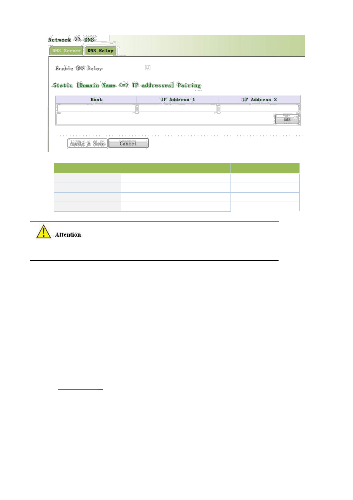
Page description is shown below:
Parameters
Description
Default
Enable DNS Relay
On/Off
On
Host
Domain Name
N/A
IP Address 1
Set IP Address 1
N/A
IP Address 2
Set IP Address 2
N/A
Once DHCP is turned on, DNS relay will be turned on as default and can’t be turned off; to turn
off DNS rely, DHCP Server has to be closed firstly.
3.3.7 Dynamic Domain Name
DDNS is the abbreviation of Dynamic Domain Name Server.
DDNS maps user's dynamic IP address to a fixed DNS service. When the user connects to the
network, the client program will pass the host’s dynamic IP address to the server program on the
service provider’s host through information passing. The server program is responsible for
providing DNS service and realizing dynamic DNS. It means that DDNS captures user's each
change of IP address and matches it with the domain name, so that other Internet users can
communicate through the domain name. What end customers have to remember is the domain name
assigned by the dynamic domain name registrar, regardless of how it is achieved.
DDNS serves as a client tool of DDNS and is required to coordinate with DDNS Server. Before
the application of this function, a domain name shall be applied for and registered on a proper website
such as www.3322.org. After the settings of dynamic domain name on WBR204n, a corresponding
relationship between the domain name and IP address of WAN port of the device is established.
TK8X5L DDNS service types include DynAccess, QDNS (3322)-Dynamic, QDNS (3322)-
Static, DynDNS-Dynamic, DynDNS-Static and NoIP.
3.3.7.1DDNS
From navigation panel, select Network >>DDNS, then enter “DDNS” page, as shown below.
55
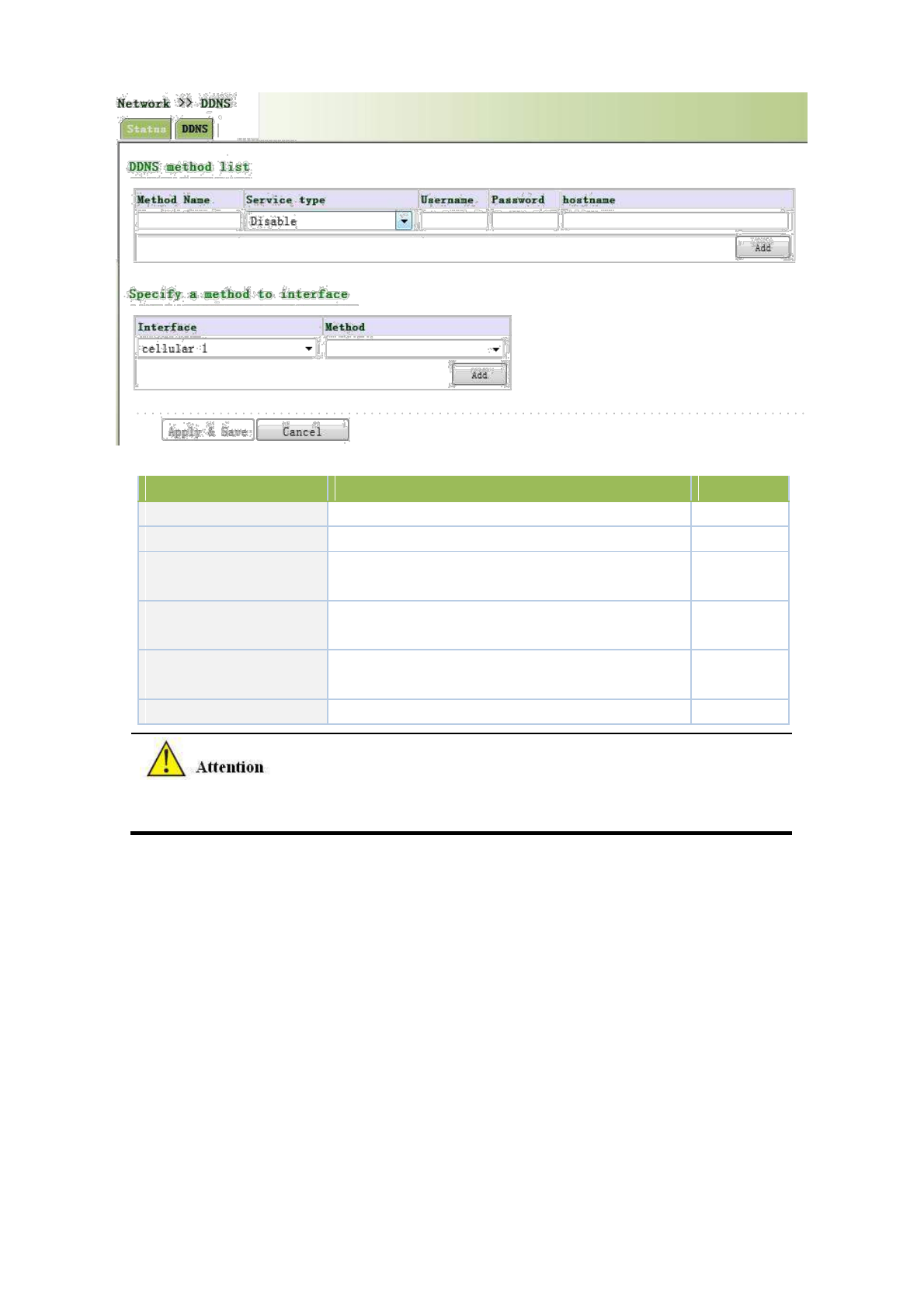
Page description is shown below:
Parameters
Description
Default
Method Name
User define
None
Service Type
Select the domain name service providers
None
User Name
User name assigned in the application for dynamic
None
domain name
Password
Password assigned in the application for dynamic
None
domain name
Host Name
Host name assigned in the application for dynamic
None
domain name
Method
The update method of specified interface
None
If the IP address obtained via router dialing is a private address, the dynamic DNS function is not
available.
3.3.7.2 DDNS Application Example
Example: an TK8X5L is connected with IP of public network via dial mode, set DDNS to address map the
dynamic IP of users on a fixed domain name service.
Configuration procedures of router are as follows:
First: Configure the parameters of dynamic domain name of equipment. Refer to Fig. 3-3-7-2 for
configuration in case of tailored domain name parameters and refer to Fig. 3-3-7-3 for configuration in case of
general domain name parameters.
56
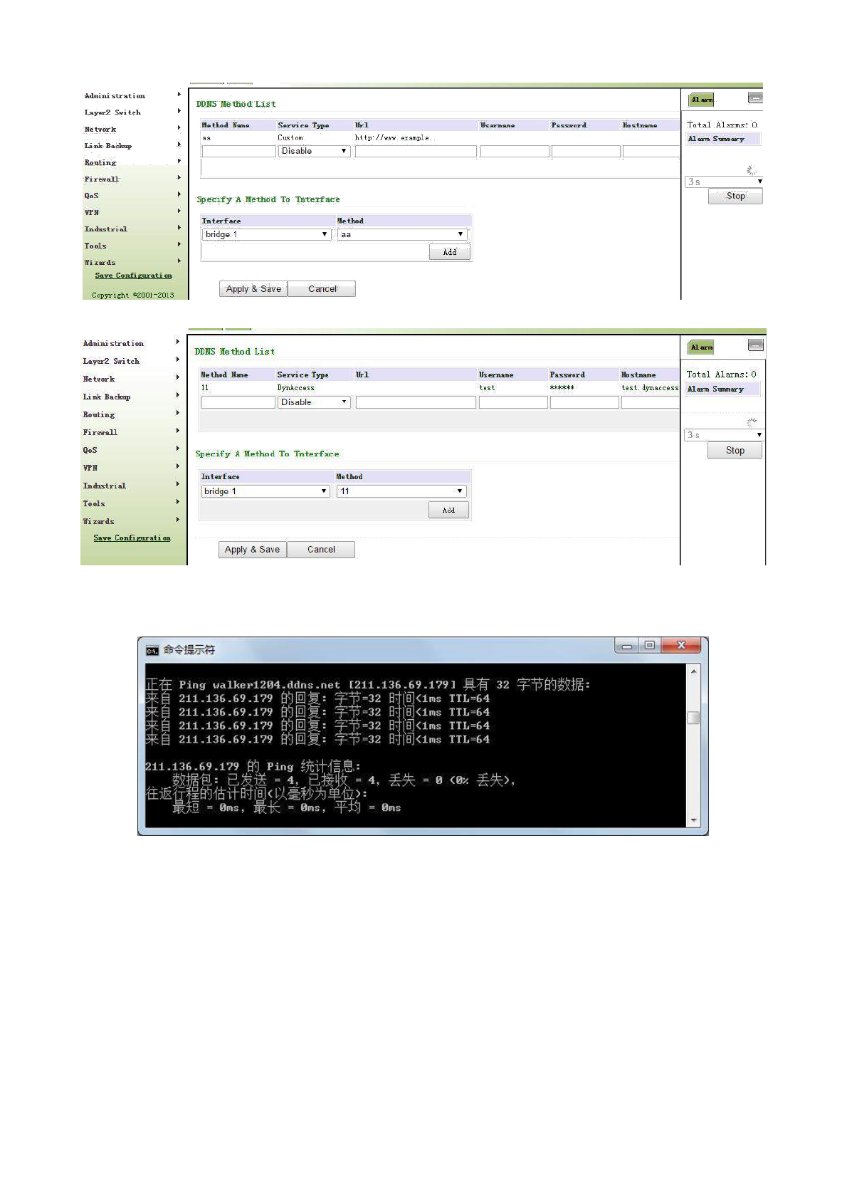
Fig. 3-3-7-2 Dynamic Domain Name (tailored domain name parameter)
Fig. 3-3-7-3 Dynamic Domain Name (general domain name parameter)
Second: Wait for minutes when dynamic domain names are configured and application is in storage, then
ping the domain name to confirm the successful configuration of dynamic domain name, as shown below:
3.3.8 SMS
SMS permits message-based reboot and manual dialing.
From navigation panel, select Network >>SMS, then enter “Basic” page, as shown below.
Configure Permit action to Phone Number and click <Apply & Save>. After that you can send
“reboot” command to restart the device or “cellular 1 ppp up/down” to redial or disconnect the device.
57
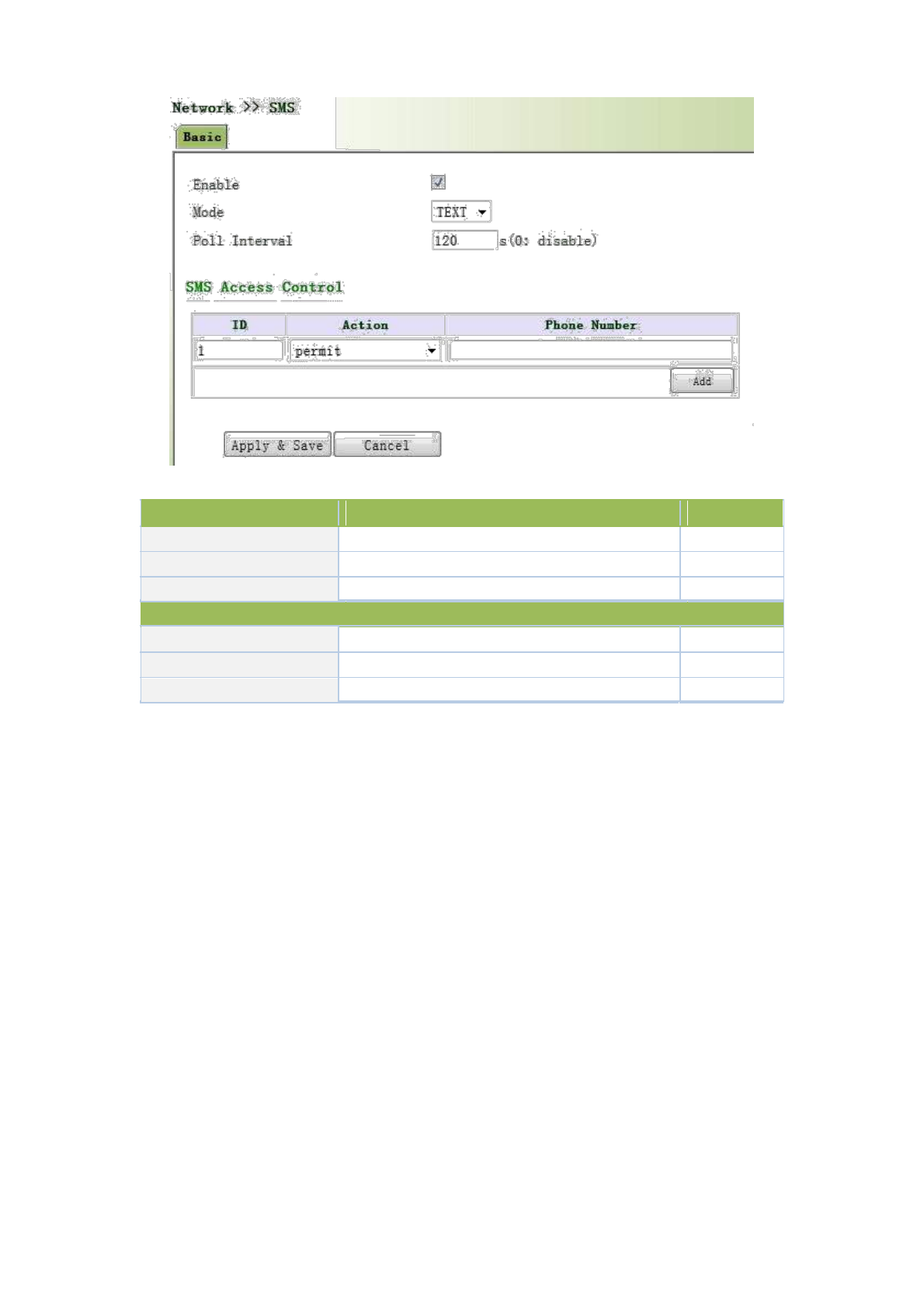
Page description is shown below:
Parameters
Description
Default
Enable
On/Off
Off
Mode
TEXT and PDU
TEXT
Poll Interval
User define Poll Interval
120
SMS Access Control
ID
User define ID
1
Action
Permit and refuseare available
Permit
Phone Number
Trusting phone number
N/A
3.4 Link Backup
3.4.1 SLA
1. Basic Concepts and Principles
Under normal circumstances, the edge router can detect if the link linked to the ISP is in fault. If the
network linking to one ISP is in fault, another ISP will be used to transmit all the data streams.
However, if the link of an ISP is normal and the infrastructure fails, the edge router will continue to
use this route. Then, the data is no longer reachable.
One feasible solution is to using static routing or policy-based routing to first test the reachability of
important destination. If it is unreachable, the static routing will be deleted.
The reachability test can be performed with Welotec SLA to continuously check the reachability of
ISP and be associated with static routing.
Basic principles of Welotec SLA: 1.Object track: Track the reachability of the specified object. 2.
SLA probe: The object track function can use Welotec SLA to send different types of detections to
the object. 3. Policy-based routing using route mapping table: It associates the track results with the
routing process. 4. Using static routing and track options.
58
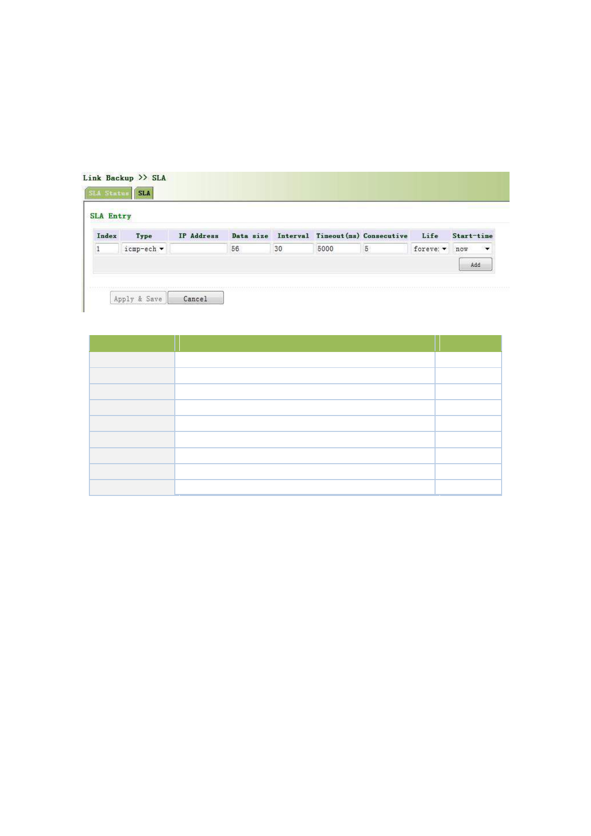
SLA Configuration Steps
Step 1: Define one or more SLA operations (detection).
Step 2: Define one or more track objects to track the status of SLA operation.
Step 3: Define measures associated with track objects.
From navigation panel, select Link Backup>>SLA, then enter “SLA” page, as shown below.
Page description is shown below:
Parameters
Description
Default
Index
SLAindex orID
1
Type
Detection type, default is icmp-echo, the user cannot change
icmp-echo
IP Address
Detected IP address
None
Data Size
User define data size
56
Interval
User define detection interval
30
Timeout (ms)
User define,Timeout for detection to fail
5000
Connecutive
Detection retries
5
Life
Default is “forever”, user cannot change
forever
Start-time
Detection Start-time, select “now” or None
now
3.4.2 Track Module
Track is designed to achieve linkage consisting of application module, Track module and monitoring module.
Linkage refers to achieve the linkage amongst different modules through the establishment of linkage items,
namely, the monitoring module could trigger application module to take a certain action through Track module.
Monitoring module is responsible for detection of link status, network performance and notification to application
module of detection results via Track module. Once the application module finds out any changes in network
status, corresponding measures will be taken on a timely basis so as to avoid interruption of communication or
reduction of service quality.
Track module is located between application module and monitoring module with main functions of shielding the
differences of different monitoring modules and providing uniform interfaces for application module.
Track Module and Monitoring Module Linkage
Through configuration, the linkage relationship between Track module and monitoring module is established.
Monitoring module is responsible for detection of link status, network performance and notification to application
module of detection results via Track module so as to carry out timely change of the status of Track item:
59
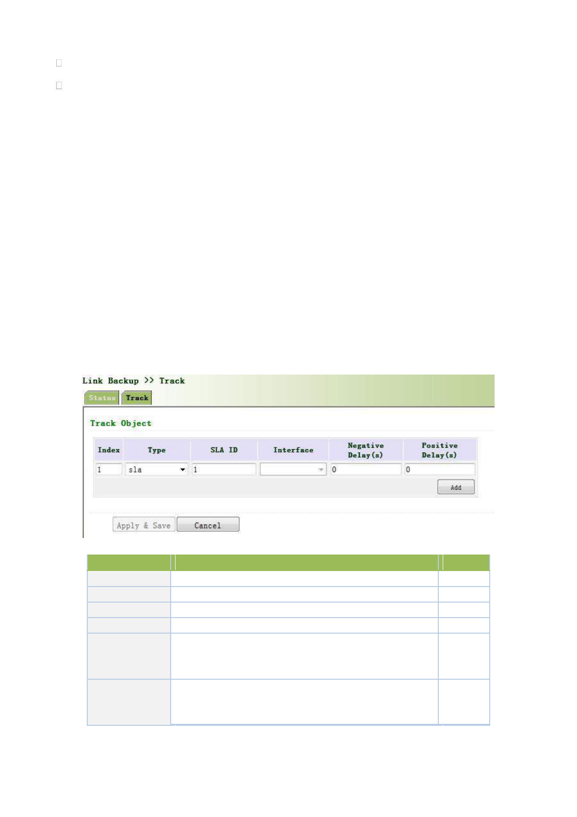
Successful detection, corresponding track item is Positive
Failed detection, corresponding track item is Negative
Track Module and Application Module Linkage
Through configuration, the linkage relationship between Track module and application module is established.
In case of any changes in track item, a notification requiring correspondent treatment will be sent to application
module.
Currently, application modules which could achieve linkage with track module include: VRRP, static routing,
strategy-based routing and interface backup.
Under certain circumstances, once any changes in Track item are founded, if a timely notification is sent to
application module, then communication may be interrupted due to routing’s failure in timely restoration and
other reasons. For example, Master router in VRRP backup group could monitor the status of upstream interface
through Track. In case of any fault in upstream interface, Master router will be notified to reduce priority so that
Backup router may ascend to the new Master to be responsible for relay of message. Once upstream interface is
recovered, so long as Track immediately sends a message to original Master router to recover priority, then the
router will take over the task of message relay. At that time, message relay failure may occur since the router has
not restored to the upstream router. Under such circumstances, user to configure that once any changes take place
in Track item, delays a period of time to notify the application module.
From navigation panel, select Link Backup>>Track, then enter “Track” page, as shown below.
Page description is shown below:
Parameters
Description
Default
Index
Track index orID
1
Type
Default “sla”,User cannot change
sla
SLA ID
Defined SLA Index or ID
None
Interface
Detect interface’s up/down state
cellular 1
Negative
Delay
In case of negative status, switching can be delayed based on
the set time (0 represents immediate switching), rather than
0
(m)
immediate switching.
Positive
Delay
In case of failure recovery, switching can be delayed based on
the set time (0 represents immediate switching), rather than
0
(m)
immediate switching.
3.4.3 VRRP
60
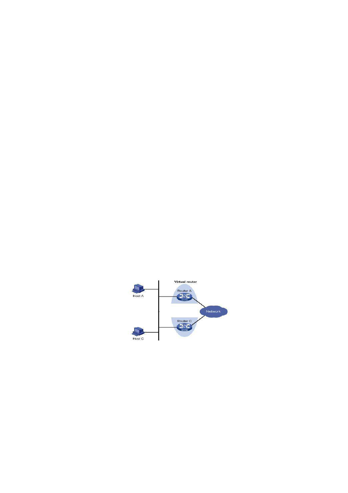
Default route provides convenience for user’s configuration operations but also imposes high
requirements on stability of the default gateway device. All hosts in the same network segment are set up
with an identical default route with gateway being the next hop in general. When fault occurs on gateway, all
hosts with the gateway being default route in the network segment can’t communicate with external network.
Increasing exit gateway is a common method for improving system reliability. Then, the problem to be
solved is how to select route among multiple exits. VRRP (Virtual Router Redundancy Protocol) adds a set of
routers that can undertake gateway function into a backup group to form a virtual router. The election mechanism
of VRRP will decide which router to undertake the forwarding task and the host in LAN is only required to
configure the default gateway for the virtual router.
VRRP will bring together a set of routers in LAN. It consists of multiple routers and is similar to a
virtual router in respect of function. According to the vlan interface ip of different network
segments, it can be virtualized into multiple virtual routers. Each virtual router has an ID number
and up to 255 can be virtualized.
VRRP has the following characteristics:
• Virtual router has an IP address, known as the Virtual IP address. For the host in LAN, it is only
required to know the IP address of virtual router, and set it as the address of the next hop of the
default route.
• Host in the network communicates with the external network through this virtual router.
• 1 router will be selected from the set of routers based on priority to undertake the gateway
function. Other routers will be used as backup routers to perform the duties of gateway for the
gateway router in case of fault of gateway router, thus to guarantee uninterrupted communication
between the host and external network
VRRP Networking Scheme:
As shown in Figure above, Router A and Router C compose a virtual router. This virtual router has its own IP
address. The host in LAN will set the virtual router as the default gateway. Router A or Router C, the one with the
highest priority, will be used as the gateway router to undertake the function of gateway. Another router will be
used as a Backup router.
Monitor interface function of VRRP better expands backup function: the backup function can be offered when
interface of a certain router has fault or other interfaces of the router are unavailable.
When interface connected with the uplink is at the state of Down or Removed, the router actively reduces its
priority so that the priority of other routers in the backup group is higher and thus the router with highest priority
becomes the gateway for the transmission task.
61

3.4.3.1 VRRP Configuration
From navigation panel, select Link Backup>>VRRP, then enter “VRRP” page, as shown below.
Page description is shown below:
Parameters
Description
Default
Enable
Enable/Disable
Enable
Virtual Route ID
User define Virtual Route ID
None
Interface
Configure the interface of Virtual Route
None
Virtual IP Address
Configure the IP address of Virtual Route
None
Parameters
Description
Default
The VRRP priority range is 0-255 (a larger number indicates
Priority
a higher priority). The router with higher priority will be
100
more likely to become the gateway router.
Advertisement
Heartbeat package transmission time interval between routers
1
Interval
in the virtual ip group
If the router works in the preemptive mode, once it finds that
its own priority is higher than that of the current gateway
Preemption Mode
router, it will send VRRP notification package, resulting in re-
Enable
election of gateway router and eventually replacing the
original gateway router. Accordingly, the original gateway
router will become a Backup router.
Track ID
Trace Detection, select the definedTrack index or ID
None
3.4.3.2 VRRP Typical Configuration Example
1. Networking Demand
Mainframe A makes VRRP backup combined with router A and router B as its default gateway to visit the
mainframe B on internet.
VRRP backup is composed of:
Backup group ID 1
IP address of backup group virtual router 192.168.2.254/24
Interchanger A Master
62
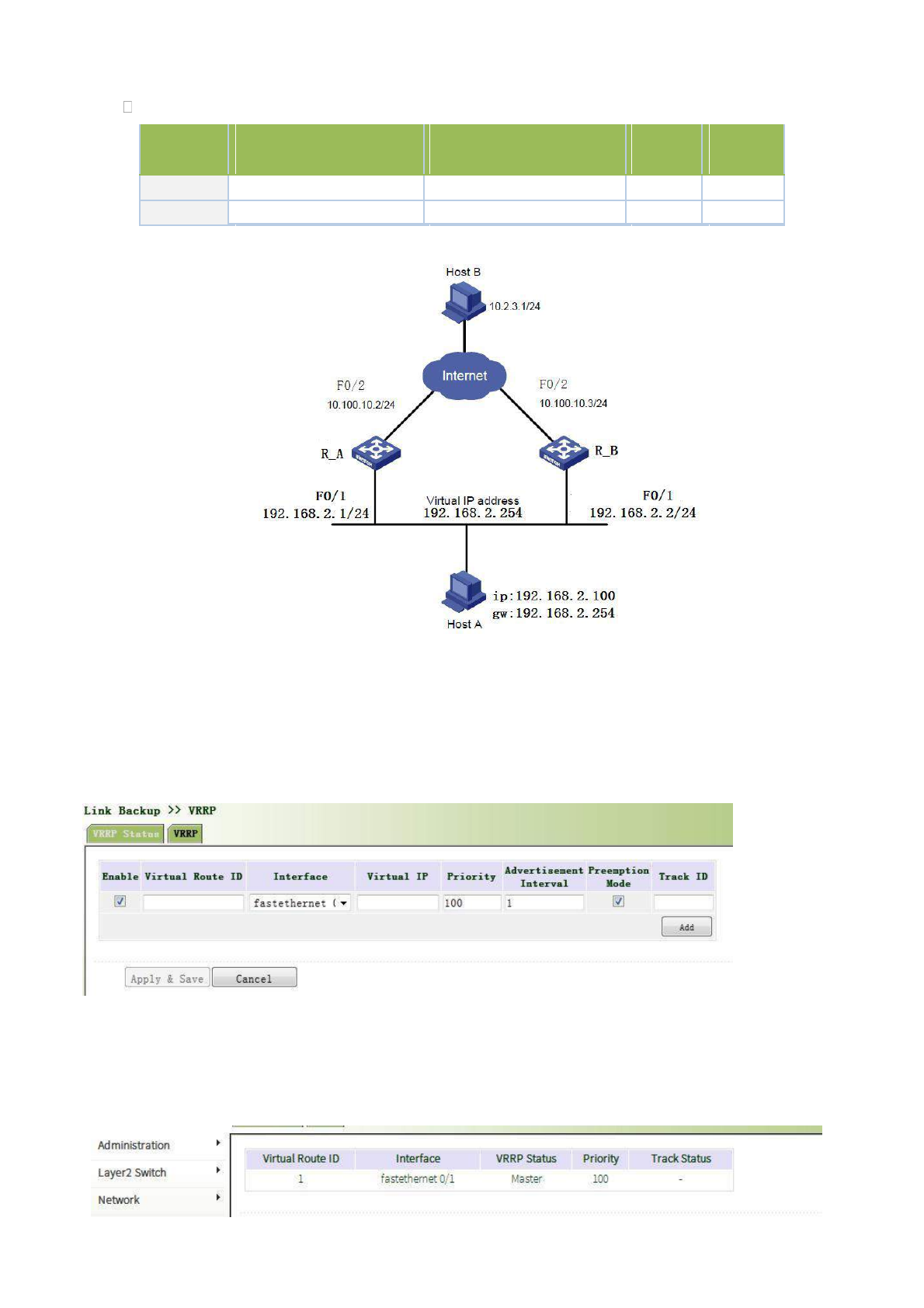
Interchanger B backup interchanger preemptive allowable
Router
Ethernet interface
IP address of interface
Priority
Working
connected with hostA
connected with hostA
mode
R_A
F0/1
192.168.2.1
110
preemptive
R_B
F0/1
192.168.2.2
100
preemptive
2. Networking Diagram
3. Configuration Procedures
(1) Configure router A
First: Configure F0/1
Click navigation panel “Link Backup>>VRRP”, enter “VRRP” interface, configure VRRP, as shown in the
following figure:
Click navigation panel “Link Backup>>VRRP”, enter “VRRP” interface, examine VRRP, as shown in the
following figure:
Second: Configure F0/2
63
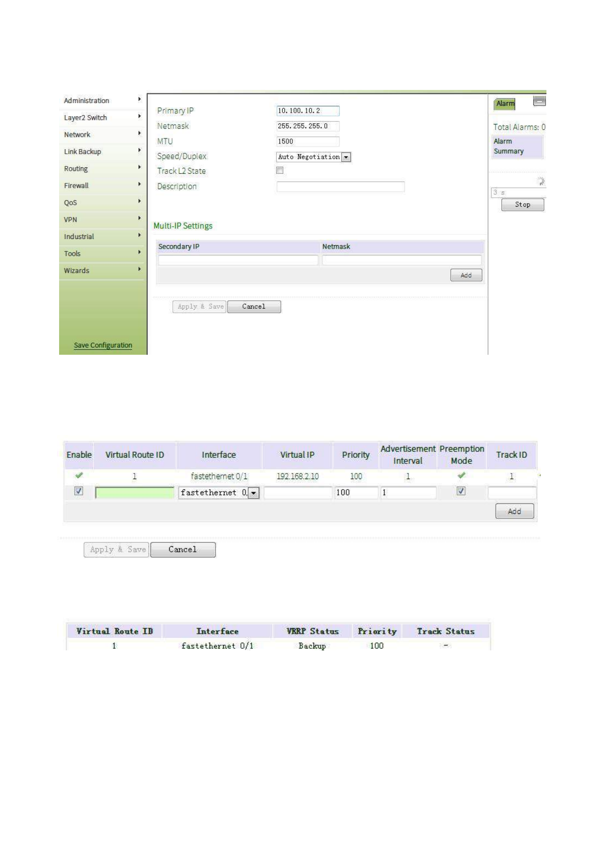
Click navigation panel “Internet>>Ethernet Interface”, enter “Ethernet Interface 0/2”, configure Ethernet
interface 0/2, as shown in the following figure:
(2) Configure router B:
First: Configure F0/1
Click navigation panel “Link Backup>>VRRP”, enter “VRRP” interface, configure VRRP, as shown in the
following figure:
Click navigation panel “Link Backup>>VRRP”, enter “VRRP” interface, examine VRRP, as shown in the
following figure:
Second: Configure F0/2
64
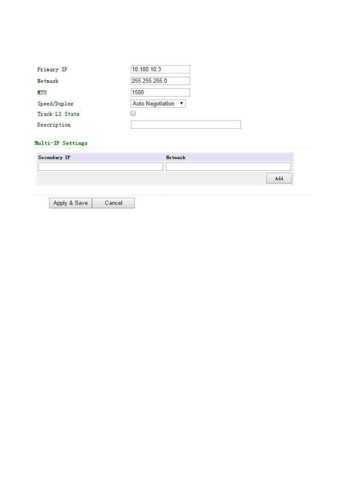
Click navigation panel “Internet>>Ethernet Interface”, enter “Ethernet Interface 0/2”, configure Ethernet
interface 0/2, as shown in Fig. 3-4-3-7:
Default gateway of mainframe A is 192.168.2.254. Router A functions as the gateway under normal working
conditions and router B will take over the function when router A closes down or breaks down. Setting
preemption is to keep the function of router A as gateway under Master when router A returns to work.
3.4.4 Interface Backup
Interface backup refers to backup relationship formed between appointed interfaces in the same equipment.
When service transmission can’t be carried out normally due to fault of a certain interface or lack of bandwidth,
rate of flow can be switched to backup interface quickly and the backup interface will carry out service
transmission and share network flow so as to raise reliability of communication of data equipment.
When link state of main interface is switched from up to down, system will wait for preset delay first instead
of switching to link of backup interface immediately. Only if the state of main interface still keeps down after the
delay, system will switch to link of backup interface. Otherwise, system will not switch.
After link state of main interface is switched from down to up, system will wait for preset delay first instead
of switching back to main interface immediately. Only if state of main interface still keeps up after the delay,
system will switch back to main interface. Otherwise, system will not switch.
3.4.4.1 Interface Backup
From navigation panel, select Link Backup>>Interface Backup, then enter “Interface
Backup” page, as shown below.
65
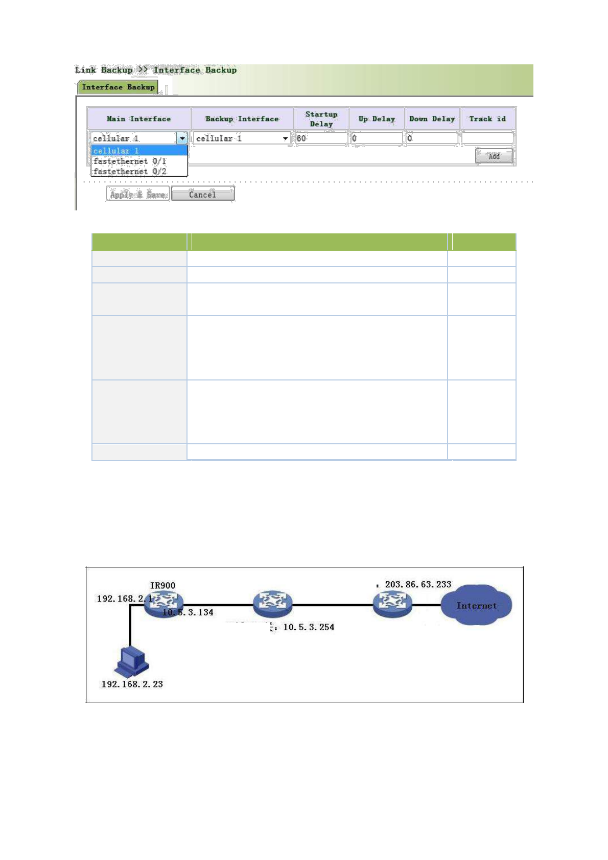
Page description is shown below:
Parameters
Description
Default
Primary Interface
The interface being used
cellular 1
Backup Interface
Interface to be switched
cellular 1
Start-up Delay
Set how long to wait for the start-up tracking detection
60
policy to take effect
When the primary interface switches from failed detection
Up Delay
to successful detection, switching can be delayed based on
0
the set time (0 represents immediate switching), rather than
immediate switching.
When the primary interface switches from successful
Down Delay
detection to failed detection, switching can be delayed
0
based on the set time (0 represents immediate switching),
rather than immediate switching.
Track ID
Trace Detection, select the definedTrack index or ID
None
3.4.4.2 Interface Backup Application Example
Example: a router TK8X5L is connected with PC at its fastethernet 0/2, fastethernet 0/1 of TK8X5L is connected
with the internet via wired network, topological graph is shown in the following figure. Establish interface backup
in configuring router so that it can surf the internet through dial-up in malfunction of wired network.
Enterprise Gateway
LAN Gateway
Configuration Procedures of router are as follows:
Step 1: Open “Wizards>>New WAN”, configure parameters of wired network, as shown in the following
figure.
66
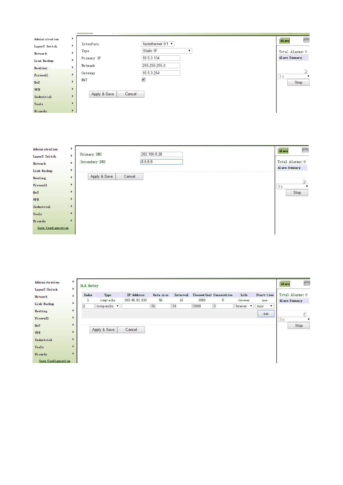
Step 2: Open “DNS” in “Network>>DNS”, configure corresponding parameters, as shown in the following
figure. Examine PC to ensure its normal access to the internet after configuration.
Step 3: Open “Link Backup>>SLA”, configure corresponding parameters, the IP address shall be the host
address explored by ICMP in public network or private network, for instance, 203.86.63.233 is the gateway
address of enterprise where PC is affiliated, as shown in the following figure.
Step 4: Open “Link Backup>>Track”, configure corresponding parameters, as shown in Fig. 3-4-4-5.
67
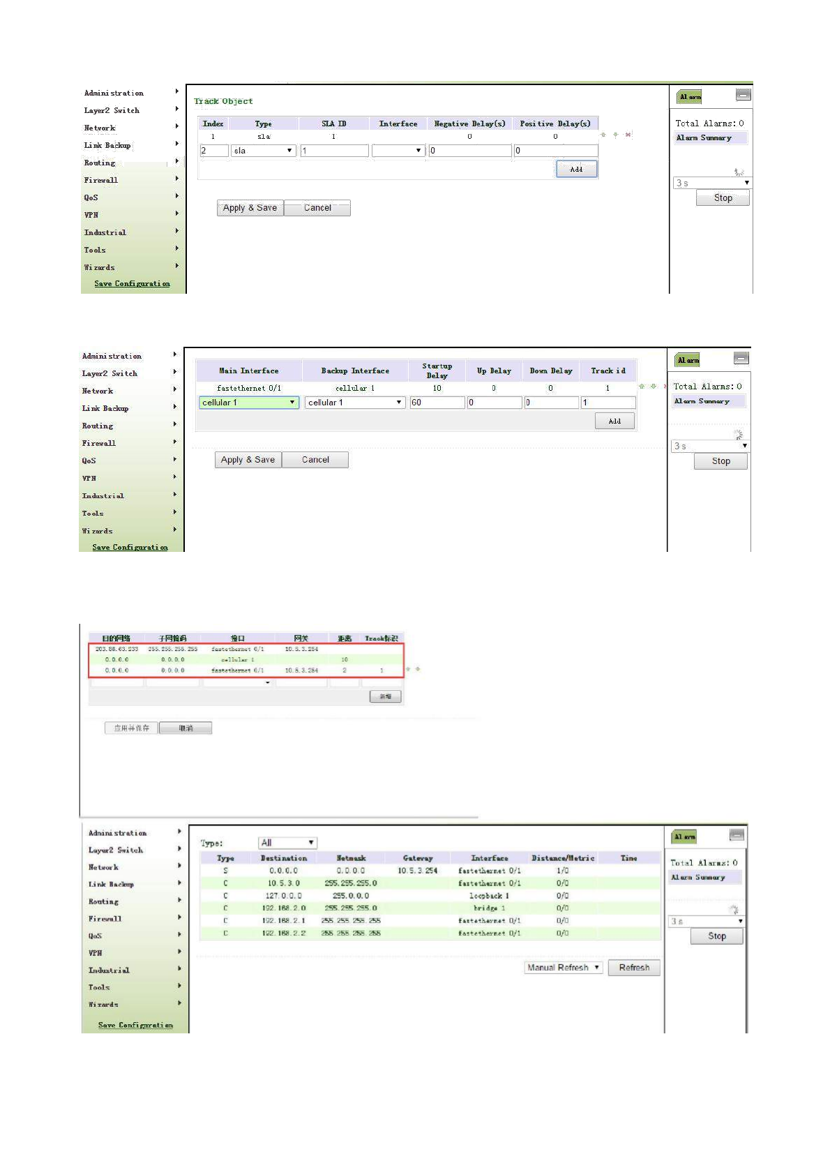
Step 5: Open “Link Backup>>Interface Backup”, configure corresponding parameters, as shown in the
following figure.
Step 6: Open “Routing>>Static Routing”, configure corresponding parameters and add 3 routes, 10.5.3.234
is the gateway of LAN where PC is affiliated, as shown below. The distance parameter indicates the priority, the
smaller the numerical the more the priorities.
Step 7: Pull up cable to make malfunction of wired internet, then router can have access to internet via dial-
up through cellular; cable internet can be applied once again when cable is set again.
68
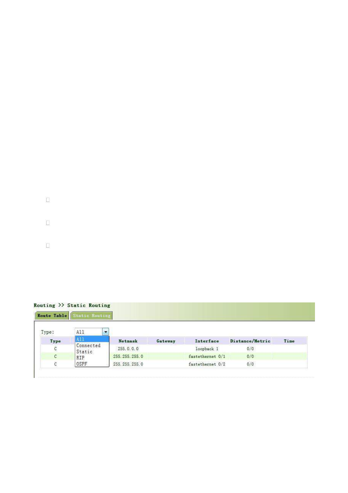
3.5 Routing
3.5.1 Static Route
Static routing is a special routing that requires your manual setting. After setting static routing,
the package for the specified destination will be forwarded according to the path designated by you.
In the network with relatively simple networking structure, it is required to set static routing to
achieve network interworking. Proper setting and use static routing can improve the performance of
network and can guarantee bandwidth for important network applications.
Disadvantages of static routing: It cannot automatically adapt to the changes in the network
topology. The network failure or changes in topology may cause the route unreachable and network
interrupted. Then, you are required to manually modify the setting of static routing.
Static Routing performs different purposes in different network environments.
When the network structure is comparatively simple, the network can work normally only with Static
Routing.
While in complex network environment, Static Routing can improve the performance of network and
ensure bandwidth for important application.
Static Routing can be used in VPN examples, mainly for the management of VPN route.
3.5.1.1 Static Routing Status
From navigation panel, select Routing>>Static Routing, then enter “Route Table” page, as shown
below.
3.5.1.2 Static Routing
From navigation panel, select Routing>>Static Routing, then enter “Static Routing,” page, as
shown below. Add/delete additional Router static routing. Normally users don not need to configure
this item.
69
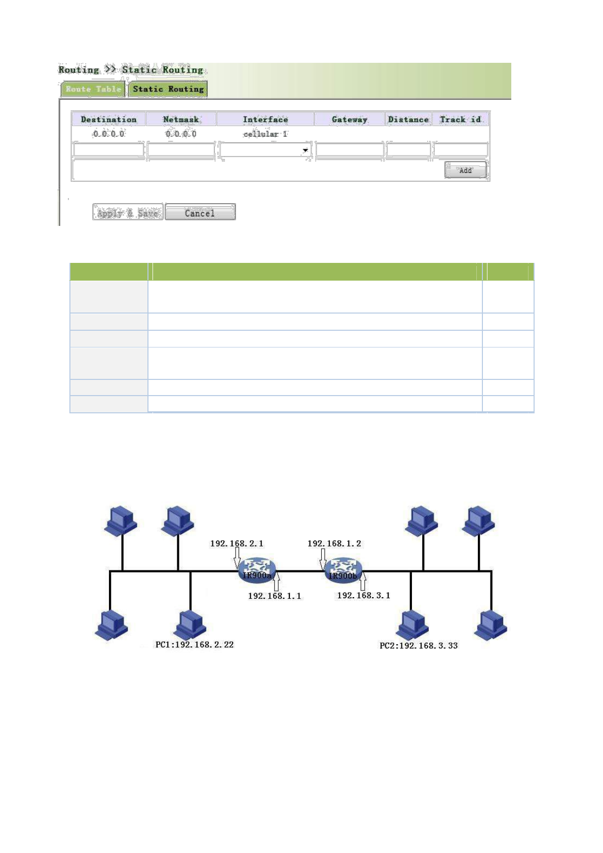
Page description is shown below:
Parameters
Description
Default
Destination
Enter the destination IP address need to be reached
0.0.0.0
address
Subnet Mask
Enter the subnet mask of destination address need to be reached
0.0.0.0
Interface
The interface through which the data reaches the destination address
Cellular1
Gateway
IP address of the next router to be passed by before the input data reaches the
None
destination address
Distance
Priority, smaller value contributes to higher priority
None
Track ID
Select the definedTrack index or ID
None
3.5.1.3 Static Routing Application Example
Example: Establish static routing between two LAN for their intercommunication; refer to the following figure for
topological graph.
Configuration procedures of router are as follows:
Step 1: Configure TK8X5La, the parameter configuration is shown in the following figure.
70
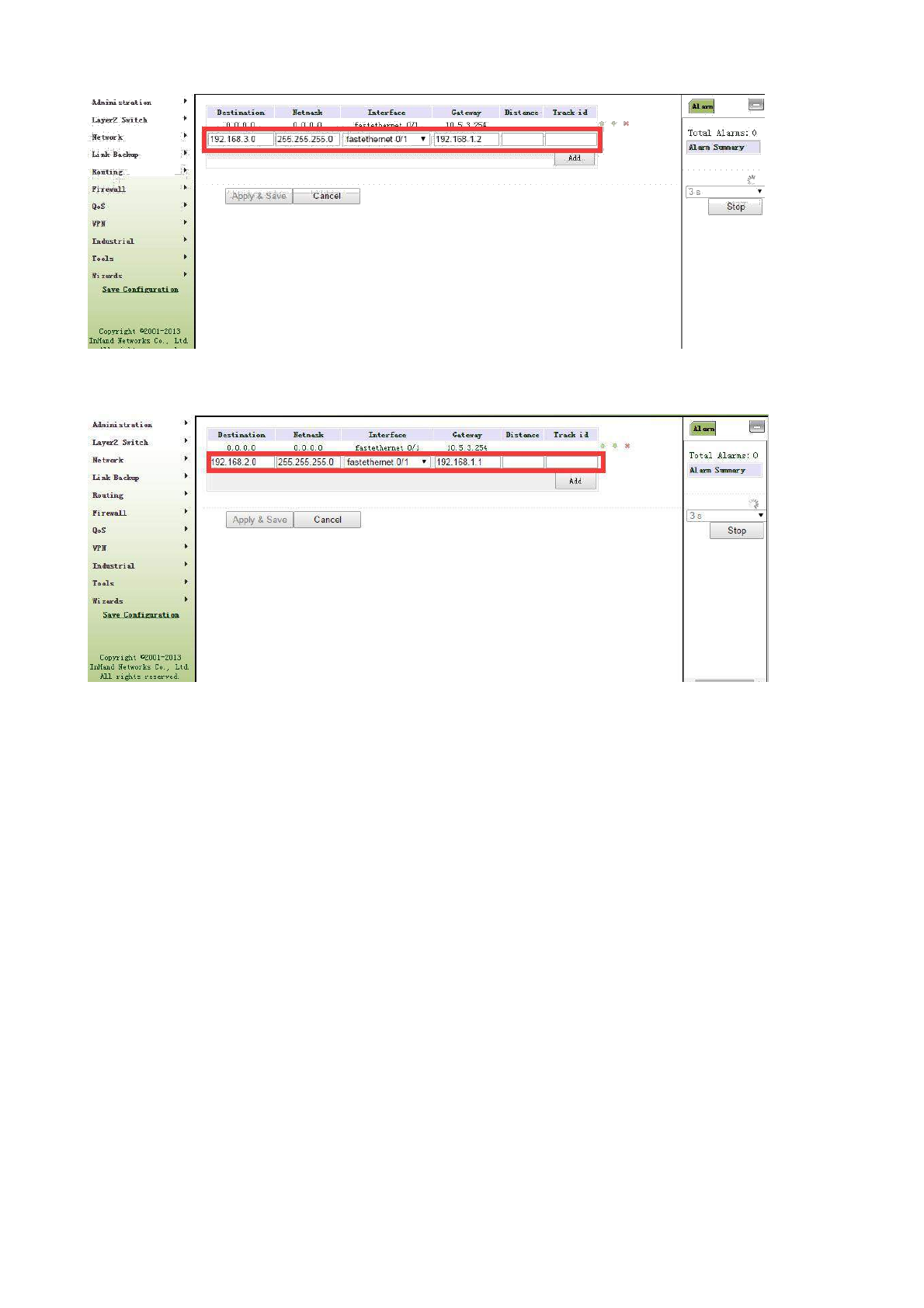
Step 2: Configure TK8X5L, parameter configuration is as follows:
Step 3: PC1 and PC2 can be intercommunicated, adding static routing is successful.
3.5.2 Dynamic Routing
The routing table entry on dynamic router is obtained in accordance with certain algorithm
optimization through the information exchange between the connected routers, while the routing
information is continuously updating in certain time slot so as to adapt to the continuously changing
network and obtain the optimized pathfinding effects at any time.
In order to achieve efficient pathfinding of IP packet, IETF has developed a variety of
pathfinding protocols, including Open Shortest Path First (OSPF) and Routing Information Protocol
(RIP) for Autonomous System (AS) interior gateway protocol. The so-called autonomous system
refers to the collection of hosts, routers and other network devices under the management of the
same entity (e.g. schools, businesses, or ISP)
3.5.2.1 Dymamic Routing status
From navigation panel, select Routing>>Dynamic Routing, then enter “Route Table” page,as
shown below.
71

3.5.2.2 RIP
RIP (Routing Information Protocol) is a relatively simple interior gateway protocol (IGP), mainly
used for smaller networks. The complex environments and large networks general do not use RIP.
RIP uses Hop Count to measure the distance to the destination address and it is called RoutingCost.
In RIP, the hop count from the router to its directly connected network is 0 and the hop count of
network to be reached through a router is 1 and so on. In order to limit the convergence time, the
specified RoutingCost of RIP is an integer in the range of 0~15 and hop count larger than or equal
to 16 is defined as infinity, which means that the destination network or host is unreachable.
Because of this limitation, the RIP is not suitable for large-scale networks. To improve performance
and prevent routing loops, RIP supports split horizon function. RIP also introduces routing obtained
by other routing protocols.
It is specified in RFC1058 RIP that RIP is controlled by three timers, i.e. Period update, Timeout
and Garbage-Collection:
Each router that runs RIP manages a routing database, which contains routing entries to reach all
reachable destinations. The routing entries contain the following information:
Destination address: IP address of host or network.
Address of next hop: IP address of interface of the router’s adjacent router to be passed by on
the way to reach the destination.
Output interface: The output interface for the router to forward package.
RoutingCost: Cost for the router to reach the destination.
Routing time: The time from the last update of router entry to the present. Each time the router
entry is updated, the routing time will be reset to 0.
From navigation panel, select Routing>>Dynamic Routing, then enter “RIP” page,as shown
below.
72
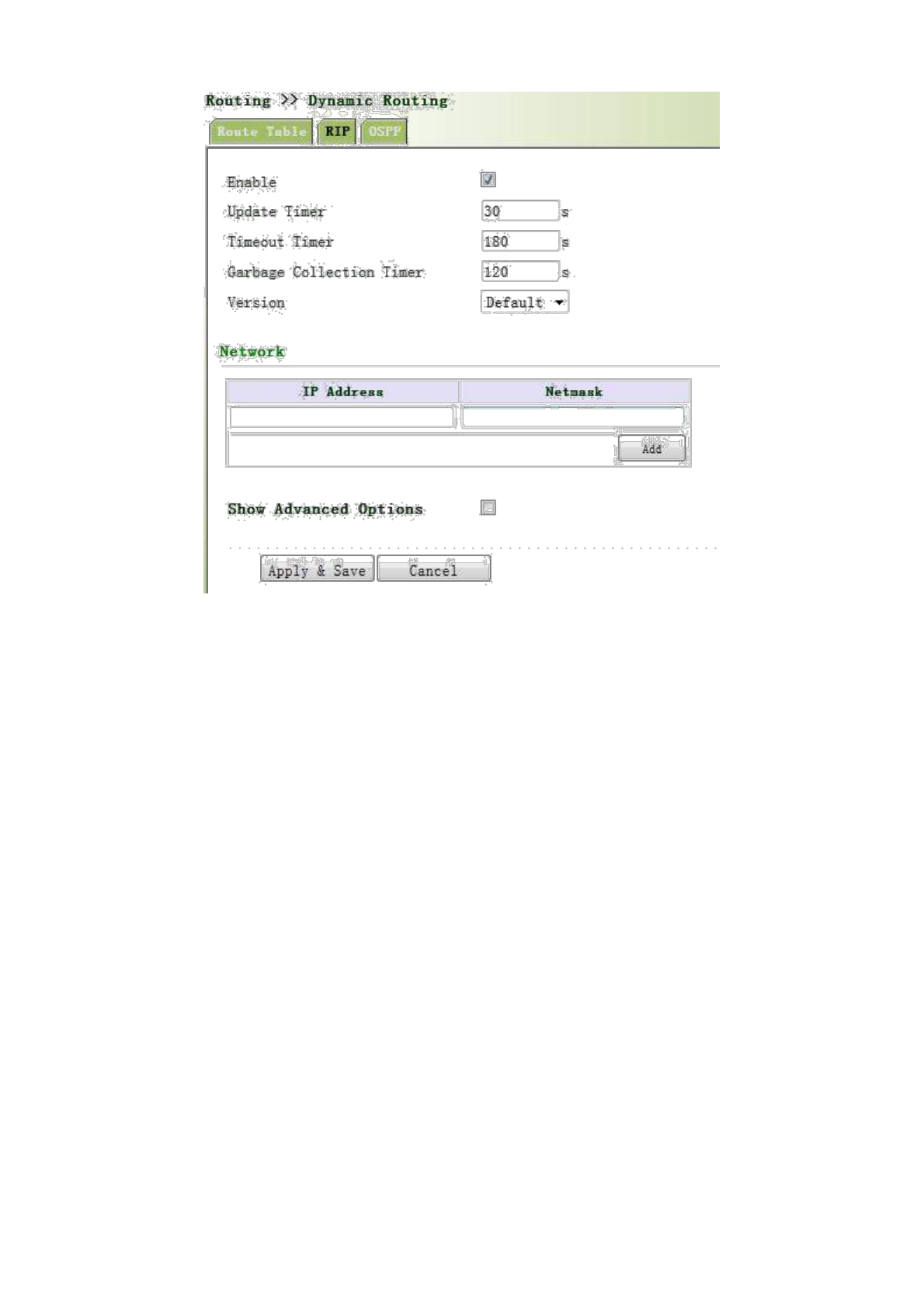
Advanced Options are shown as below.
73
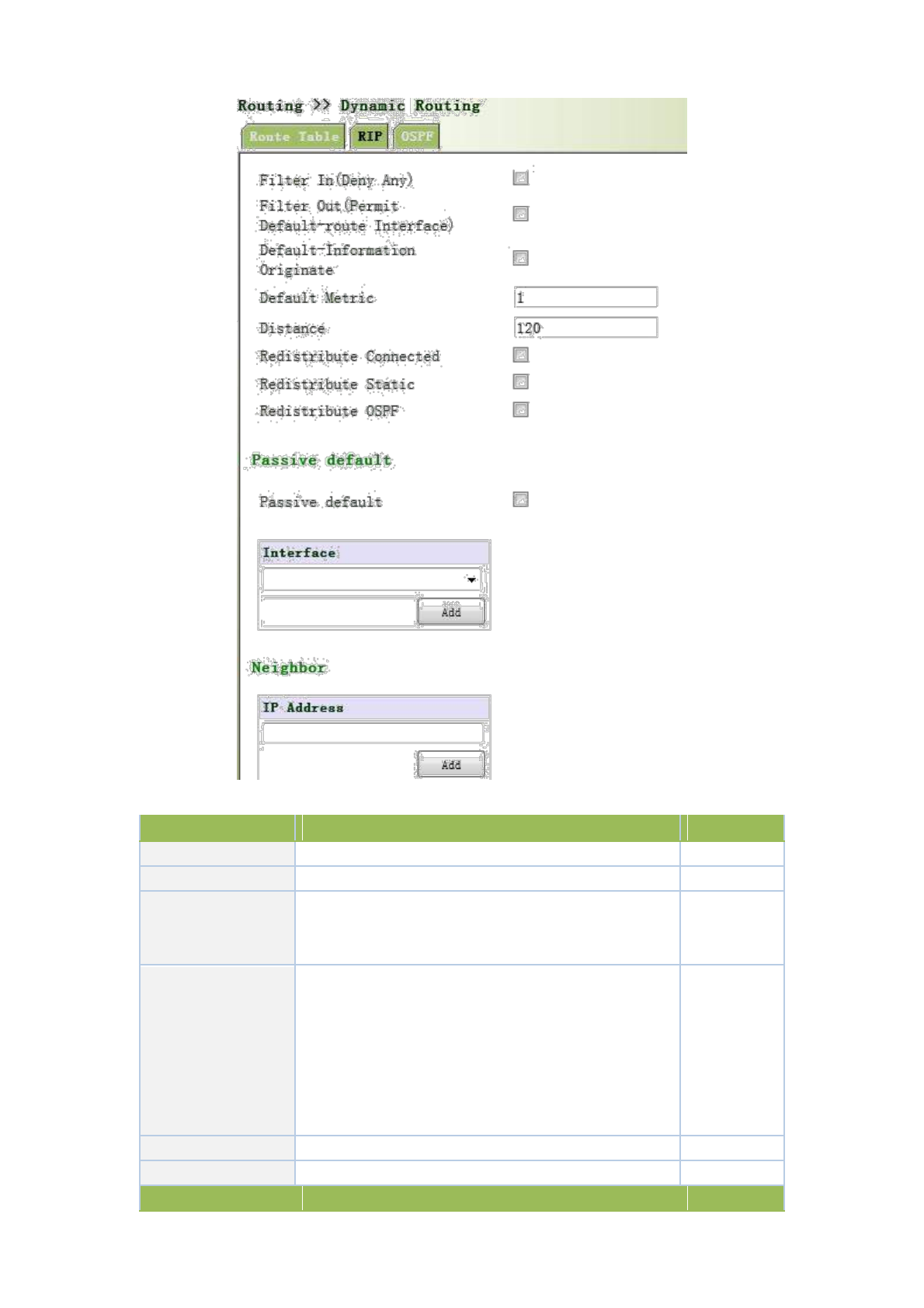
Page description is shown below:
Parameters
Description
Default
Enable
Enable/ Disable
Disable
Update timer
It defines the interval to send routing updates
30
It defines the routing aging time. If no update package on
Timeout timer
a routing is received within the aging time, the routing’s
180
Routing Cost in the routing table will be set to 16.
It defines the time from the time when the RoutingCost
of a routing becomes 16 to the time when it is deleted
from the routing table. In the time of Garbage-Collection,
Clear Timer
RIP uses 16 as the RoutingCost for sending updates of
120
the routing. In case of timeout of Garbage-Collection and
the routing still has not been updated, the routing will be
completely removed from the routing table.
Version
Version number of RIP
V2
Network
The first IP addressand subnet mask of the segment
None
Advanced Options
74

Filter In
Only send RIP packets do not receive RIP packets
Disable
Filter Out
RIP packets sent to the default routing interface
Disable
Default-Information
Default information will be released
Disable
Originate
Default Metric
The default overhead of the router reach to destination
1
Distance
Set the RIP routing administrative distance
120
Redistribute router
Introduce the directly connected, static, OSPF protocols
Disable
into the RIP protocol
Passivie Default
Interfaceonly receivesRIP packetsdo notsend RIP
None
packets
Neighbor
For neighboring routers, after configuring neighbors, rip
None
package will only be sent to neighboring routers
3.5.2.3 OSPF
Open Shortest Path First (OSPF) is a link status based interior gateway protocol developed by IETF.
Router ID
If a router wants to run the OSPF protocol, there should be a Router ID. Router ID can be manually
configured. If no Router ID is configured, the system will automatically select one IP address of
interface as the Router ID.
The selection order is as follows:
If a Loopback interface address is configured, then the last configured IP address of Loopback
interface will be used as the Router ID;
If no LoopBack interface address is configured, choose the interface with the biggest IP adress
from other interfaces as the Router ID.
OSPF has five types of packets:
Hello Packet
DD Packet (Database Description Packet)
LSR packet (Link State Request Packet)
LSU Packet (Link State Update Packet)
LSAck packet (Link State Acknowledgment Packet)
Neighbor and Neighboring
After the start-up of OSPF router, it will send out Hello packets through the OSPF interface. Upon
receipt of Hello packet, OSPF router will check the parameters defined in the packet. If both are
consistent, a neighbor relationship will be formed. Not all both sides in neighbor relationship can
form the adjacency relationship. It is determined based on the network type. Only when both sides
successfully exchange DD packets and LSDB synchronization is achieved, the adjacency in the true
sense can be formed. LSA describe the network topology around a router, LSDB describe entire
network topology.
From navigation panel, select Routing>>Dynamic Routing, then enter “OSPF” page,as shown
75
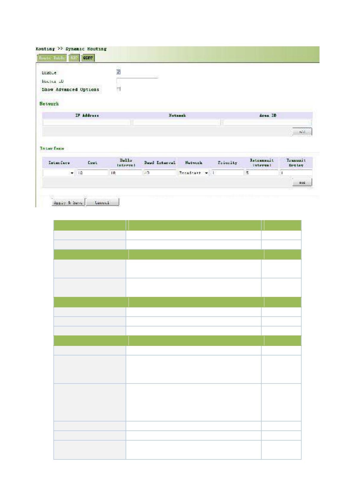
below.
Page description is shown below:
Parameters
Description
Default
Enable
Enable/Disable
Disable
Router ID
RouterID oftheoriginating the LSA
None
Advanced Options
Default Metric
The default overhead of the router reach to
None
destination
Redistribute Router
Introduce the directly connected, static, RIP
Disable
protocols into the OSPF protocol
Network
IP Address
IP Address of local network
None
Subnet Mask
Subnet Mask of IP Address of local network
None
Area ID
Area ID of router which originating LSA
None
Interface
Interface
The interfae
None
Send interval of Hello packet. If the the Hello time
Hello Interval
between two adjacent routers is different, you can
None
not establish a neighbor relationship.
Dead Time. If no Hello packet is received from the
Dead Interval
neighbors, the neighbor is considered failed. If dead
None
times of two adjacent routers are different, the
neighbor relationship can not be established.
Network
Select OSPF network type
None
Priority
Set the OSPF priority of interface
None
Retransmit Interval
When the router notifies an LSA to its neighbor, it
None
is required to make acknowledgement. If no
76
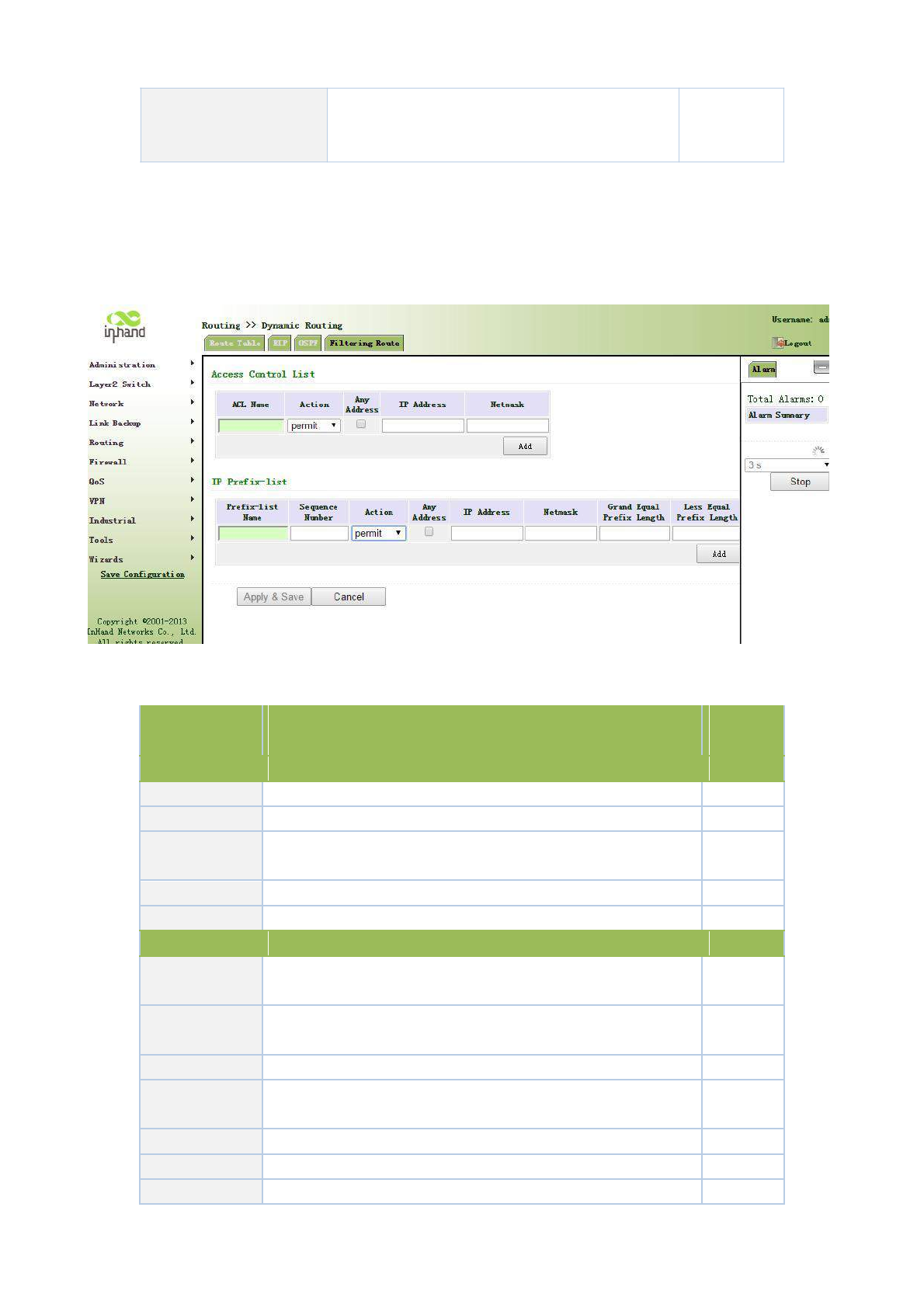
acknowledgement packet is received within
the retransmission interval, this LSA will be
retransmitted to the neighbor.
3.5.2.4 Filtering Route
Click navigation panel “Routing>>Dynamic Routing” menu, enter “Filtering Route” interface, as shown
in the following figure.
Page information is shown below:
Parameter
Description
Default
Name
Value
Access Control List
Access list
User defined
None
Action
Permit and deny
Permit
Any Address
Any address after clicking, no matching IP address and subnet
Forbidden
mask again
IP Address
User defined
None
Subnet Mask
User defined
None
Prefix List
PrefixName
User defined
None
List
Serial Number
A prefix name list can be matched with multiple rules, one rule is
None
matched with one serial number
Action
Permit and deny
Permit
Any Address
Any address after clicking, no matching IP address and subnet
None
mask again
IP Address
User defined
None
Subnet Mask
User defined
None
Grand Equal
Filling in network marking length of subnet mask and restricting
None
77
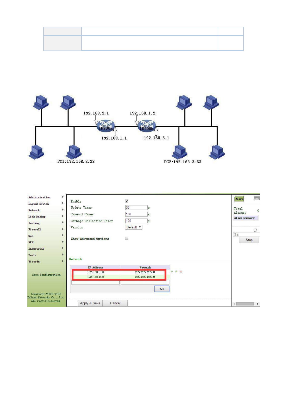
Prefix Length
the minimum IP address in IP section
Less Equal
Filling in network marking length of subnet mask and restricting
None
Prefix Length
the maximum IP address in IP section
3.5.2.5 Dynamic Routing Application Example
Example: Establish dynamic routing between two LANs for intercommunication; refer to the following figure for
the topological graph.
1. RIP
Configuration procedures of router are as follows:
First: Configure TK8X5La; refer to the following figure for the parameter configuration.
Second: Configure TK8X5Lb and refer to the following figure for parameter configuration.
78
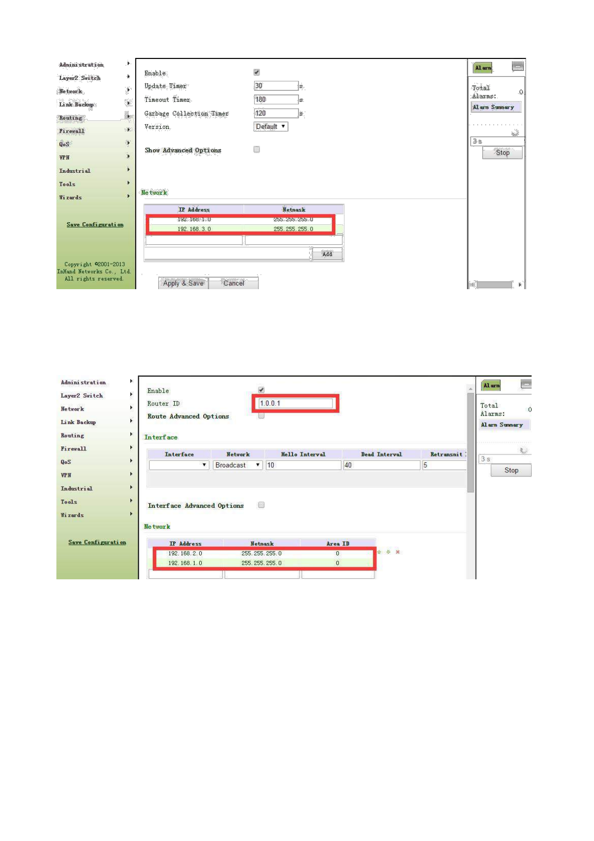
Third: PC1 and PC 2 can be intercommunicated and adding dynamic routing is successful.
2. OSPF
Configuration procedures of router are as follows:
First: Configure TK8X5La and refer to the following figure for parameter configuration.
Second: Configure TK8X5Lb and refer to the following figure for parameter
configuration.
79
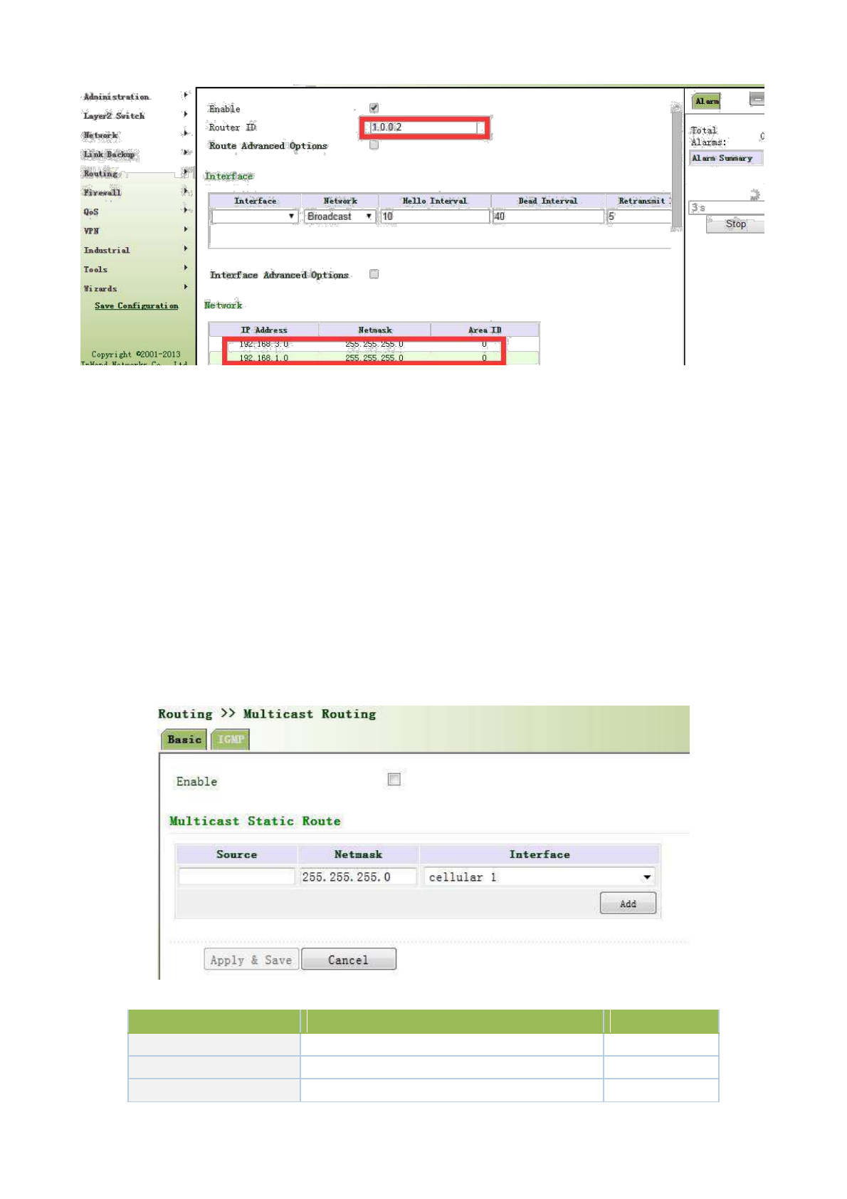
Third: PC1 and PC2 can be intercommunicated and adding dynamic routing is successful.
3.5.3 Multicast Routing
Multicast routing sets up an acyclic data transmission route from data source end to multiple receiving ends,
which refers to the establishment of a multicast distribution tree. The multicast routing protocol is used for
establishing and maintaining the multicast routing and forrelaying multicast data packet correctly and efficiently.
3.5.3.1 Basic
The basic is mainly to define the source of multicast routing.
From navigation panel, select Routing>>Multicast Routing, then enter “Basic” page,as
shown below.
Page description is shown below:
Parameters
Description
Default
Enable
Open/Close
Close
Source
IP Address of Source
None
Netmask
Netmask of Source
255.255.255.0
80
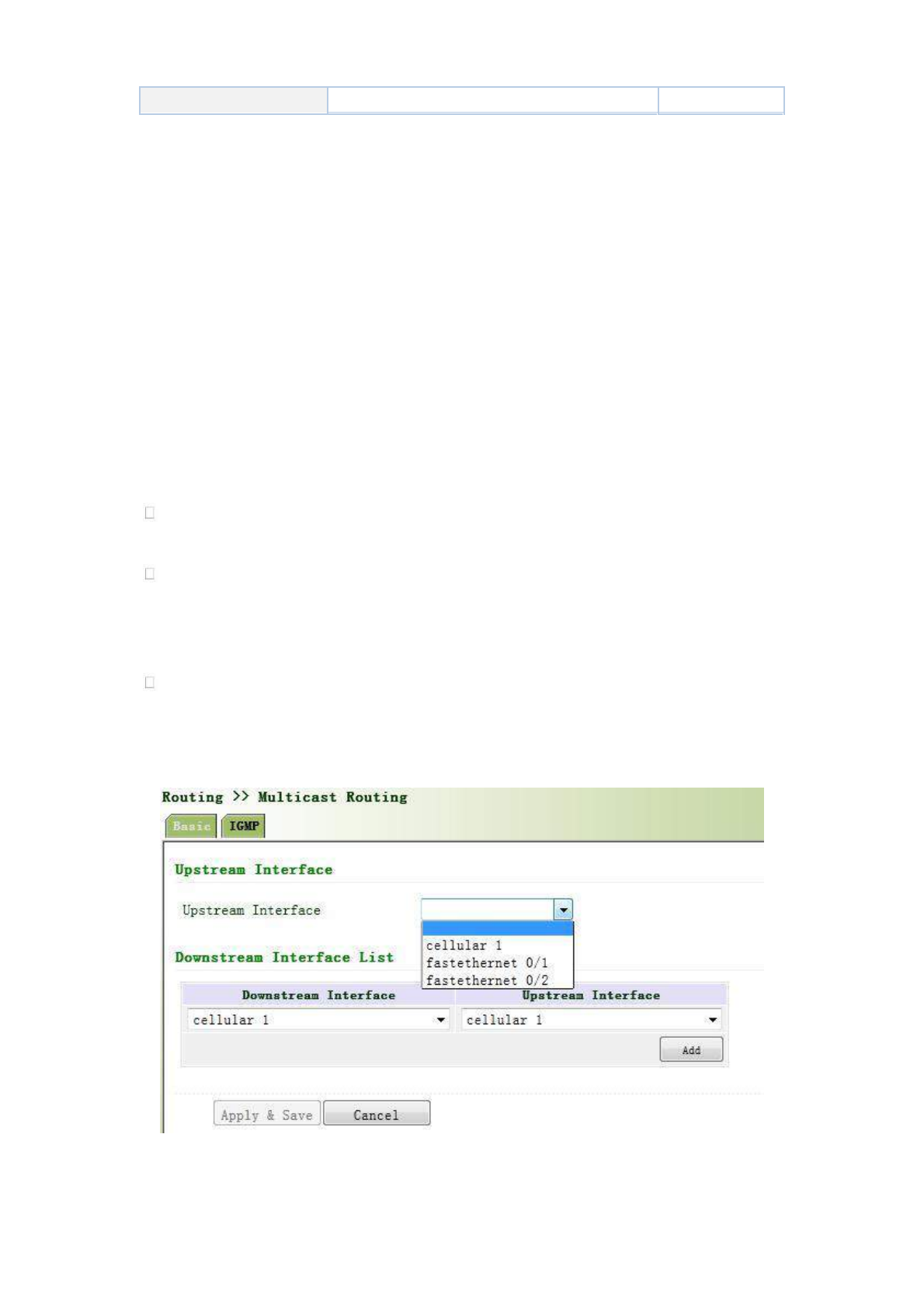
Interface
Interface of Source
cellular1
3.5.3.2 IGMP
IGMP, being a multicast protocol in Internet protocol family, which is used for IP host to report its constitution to
any directly adjacent router, defines the way for multicast communication of hosts amongst different network segments
with precondition that the router itself supports multicast and is used for setting and maintaining the relationship
between multicast members between IP host and the directly adjacent multicast routing. IGMP defines the way for
maintenance of member information between host and multicast routing in a network segment.
In the multicast communication model, sender, without paying attention to the position information of
receiver, only needs to send data to the appointed destination address, while the information about receiver will be
collected and maintained by network facility. IGMP is such a signaling mechanism for a host used in the network
segment of receiver to the router. IGMP informs the router the information about members and the router will
acquire whether the multicast member exists on the subnet connected with the router via IGMP.
Function of multicast routing protocol:
Discovering upstream interface and interface closest to the source for the reason that multicast
routing protocol only cares the shortest route to the source.
Deciding the real downstream interface via (S, G). A multicast tree will be finished after all routers
acquire their upstream and downstream interfaces with root being router directly connected with the
source host and branches being routers directly connected via subnet with member discovered by
IGMP.
Managing multicast tree. The message can be transferred once the address of next hop can be
acquired by unicast routing, while multicast refers to relay message generated by source to a group.
From navigation panel, select Routing>>Multicast Routing, then enter “IGMP” page,as
shown below.
3.5.3.3 Multicast Routing Application Example
81
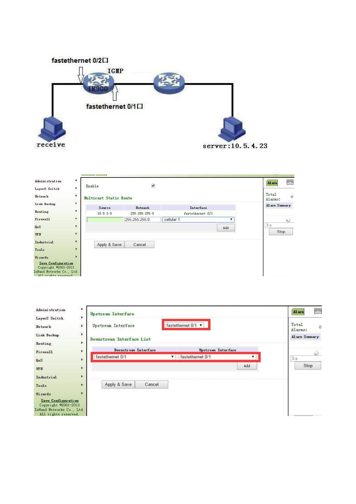
Example: Set router to receive the multicast data from network and refer to the following figure for topological
graph.
Configuration procedures of router are as follows:
Step 1: Start multicast routing and configure parameters for multicast routing, as shown in the following figure.
Step 2: Configure IGMP parameter, as shown in the following figure.
3.6 Firewall
With the expansion of network and increase in flow, the control over network safety and the allocation
82
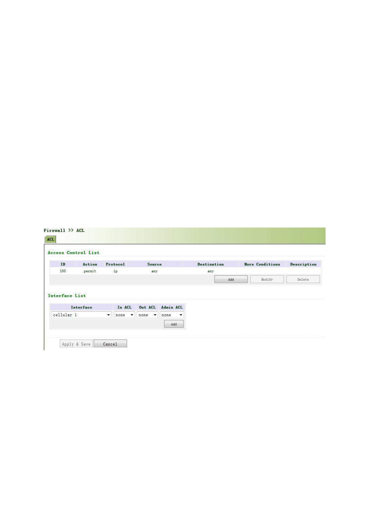
of bandwidth become the important contents of network management. The firewall function of the
router implements corresponding control to data flow at entry direction (from Internet to local area network) and
exit direction (from local area network to Internet) according to the content features of message (such as: protocol
style, source/destination IP address, etc.) and ensures safe operation of router and host in local area network.
3.6.1 Access Control
ACL, namely access control list, implements permission or prohibition of access for appointed data flow
(such as prescribed source IP address and account number, etc.) via configuration of a series of matching rules so
as to filter the network interface data. After message is received by port of router, the field is analyzed according
to ACL rule applied on the current port. And after the special message is identified, the permission or prohibition
of corresponding packet is implemented according to preset strategy.
ACL classifies data packages through a series of matching conditions. These conditions can be
data packages’ source MAC address, destination MAC address, source IP address, destination IP
address, port number, etc.
The data package matching rules as defined by ACL can also be used by other functions
requiring flow distinguish.
From navigation panel, select Firewall>>ACL, then enter “ACL” page,as shown below.
Click <Add> to add new access control list, as shown below.
83
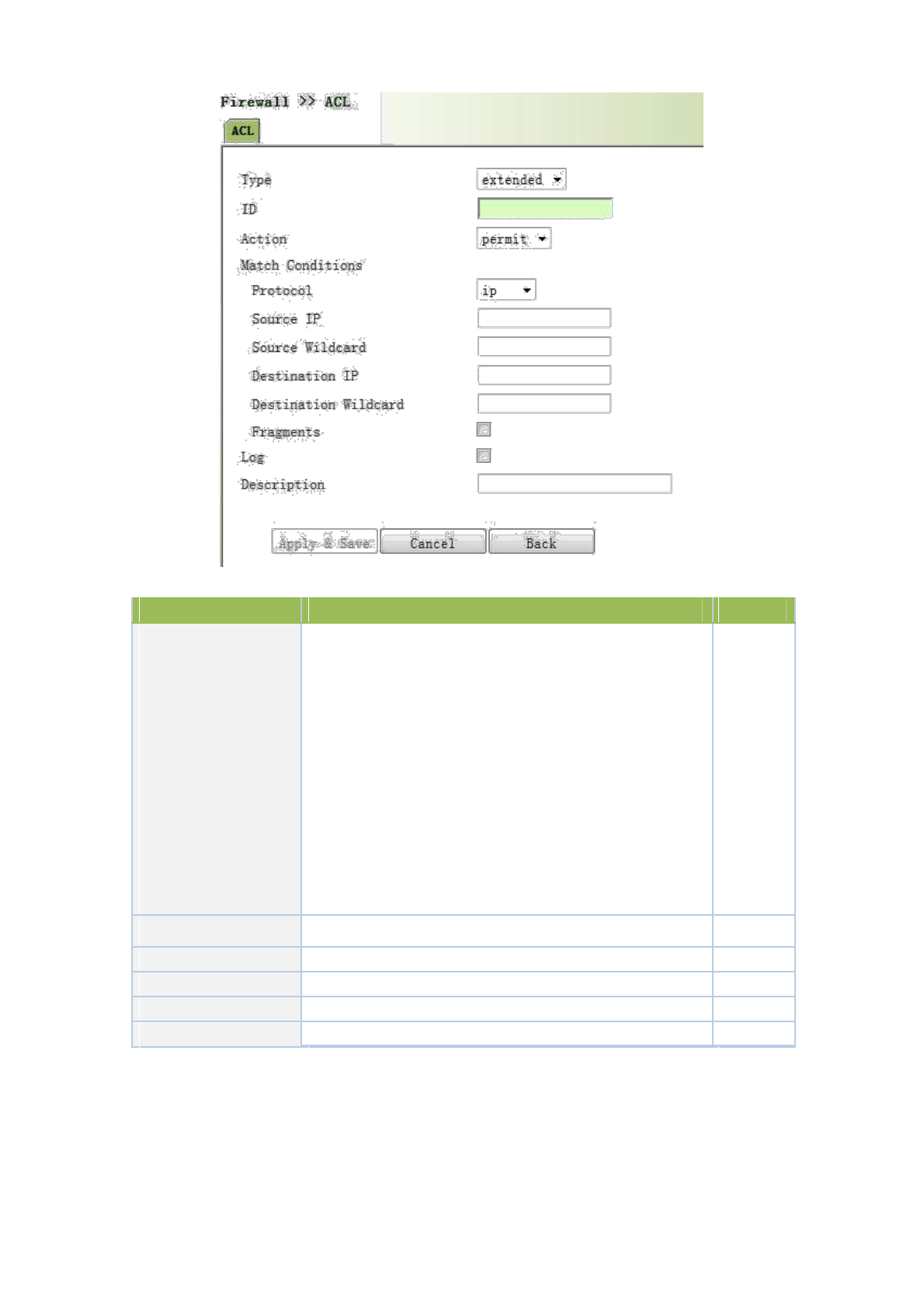
Page description is shown below:
Parameters
Description
Default
Standard ACL can block all communication flows
from a network, or allow all communication flows
from a particular network, or deny all communication
flows of a protocol stack (e.g. IP) of.
The extended ACL
provides a wider range of control
Type
than that provided by the standard ACL. For example,
Extended
if the network administrator wants to "allow external
Web communication flows to pass through and reject
external communication flows, e.g. FTP and Telnet”,
the extended ACL can be used to achieve the
objective. The standard ACL can not be controlled so
precisely.
ID
User define
Permit
Action
Permit/Deny
Permit
Protocol
Access Control Protocol
ip
Source IP Address
IP Address of Source
None
Destination IP
IP Address of Destination
None
3.6.1.1 ACL
Click navigation panel “Firewall>>ACL” menu, enter “ACL” interface, as shown in the following figure.
84
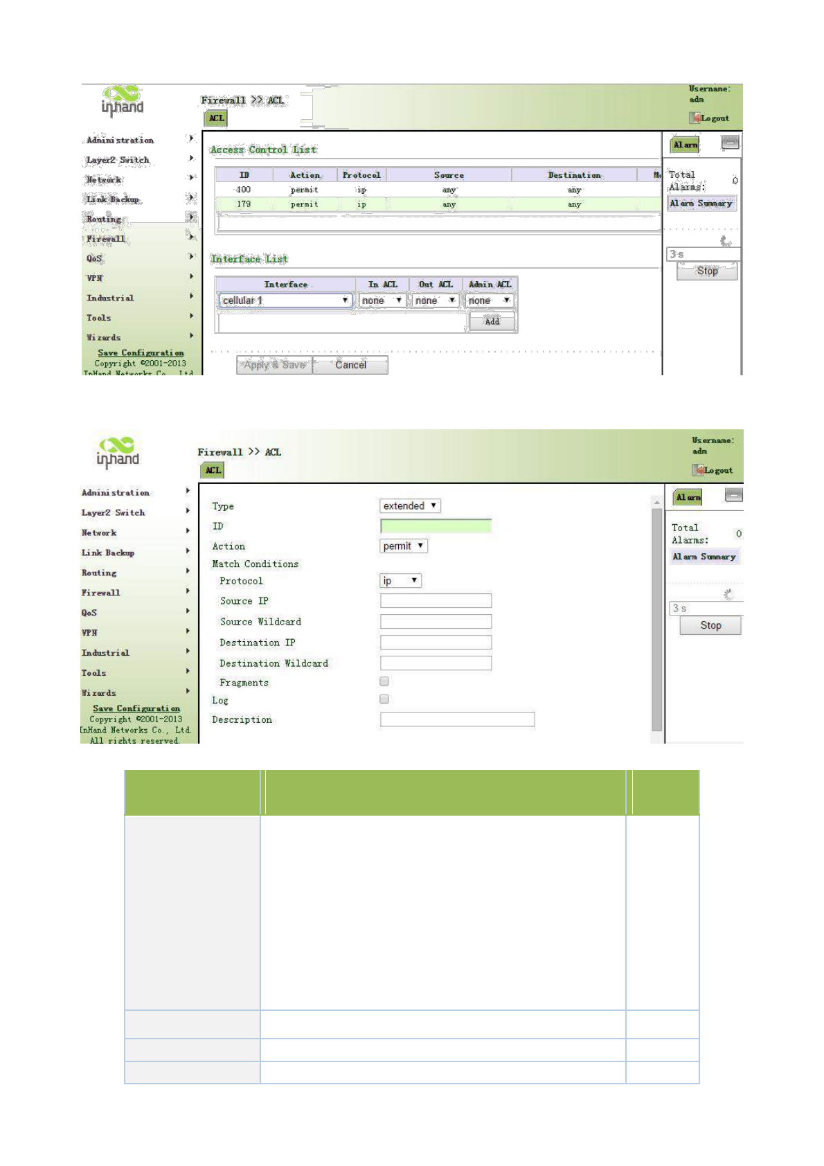
Click <Add>, enter the new configuration interface and add new ACL list, as shown in the following figure.
Page information is shown below:
Parameter Name
Description
Default
Value
Standard ACL can prevent all the communication flow of
some network or permit all the communication flow of some
network or refuse all the communication flow of some
protocol stack (like IP).
Type
Expanded ACL can provide more extensive control scope
Expanded
than standard ACL does. For instance, network manager can
make use of expanded ACL instead of standard ACL to
permit Web communication flow, refuse FTP and Telnet
because the control of ACL is not as desired.
ID
User self-defined number
No
Action
Permit/refuse
Permit
Agreement
ACP
Ip
85
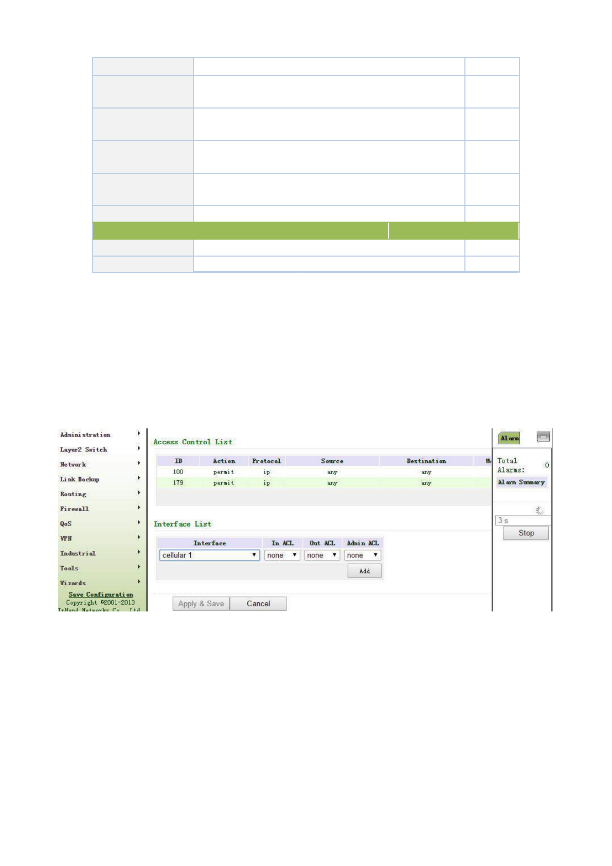
Source IP address
Source network address (blank in case of any configuration)
No
Source
address
Radix-minus-one complement of mask in source network
No
wildcard mask
address
Destination
IP
Destination network
address (blank in
case
of
any
No
address
configuration)
Destination
address
Radix-minus-one complement of mask in destination address
No
wildcard mask
Writing log
Click starting and the
log about access
control
will
be
Forbidden
recorded in the system after starting
Description
Convenient for recording parameters of access control
No
Network Interface List
Port name
Select the name of network interface
cellular1
Rule
Select the rules for in and out and management
none
3.6.1.2 Access Control Application Example
Example: a router TK8X5L is connected with intranet at its FE 0/1, the net section of intranet is 192.168.1.2/254;
FE 0/2 is connected with intranet, net section of intranet is 192.168.2.2/254. configure router for no access into the
internet with FE 0/2 and access into Internet can be realized when FE 0/1 is connected with intranet.
Configuration procedures of router are as follows:
Step 1: Open “ACL”, click <add> for access control list and configure parameters as shown in the following
figure.
Step 2: Click <Apply and Store> when parameter configuration is done, then ID “101” can be seen on the
newly established access control list.
86
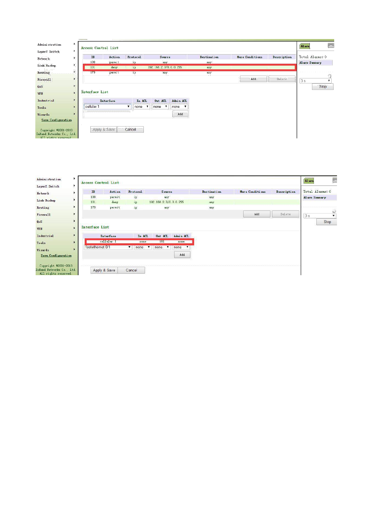
Step 3: Select “cellular1” in “Port Name” of “Network Port List”, select “101” in “Out Rules”, click <add>
and store, as shown in the following figure.
3.6.2 NAT
NAT can achieve Internet access by multiple hosts within the LAN through one or more public
network IP addresses. It means that few public network IP addresses represent more private
network IP addresses, thus saving public network IP addresses.
From navigation panel, select Firewall>>NAT, then enter “NAT” page,as shown below.
87
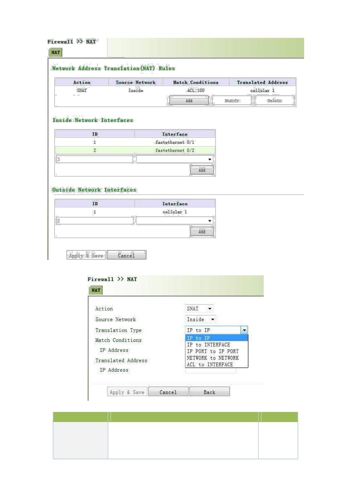
Click <Add>to add new NAT rules, as shown below.
Page description is shown below:
Parameters
Description
Default
SNAT:Source NAT: Translate IP packet's source
Action
address into another address
SNAT
DNAT:Destination NAT: Map a set of local internal
addresses to a set of legal global addresses.
88
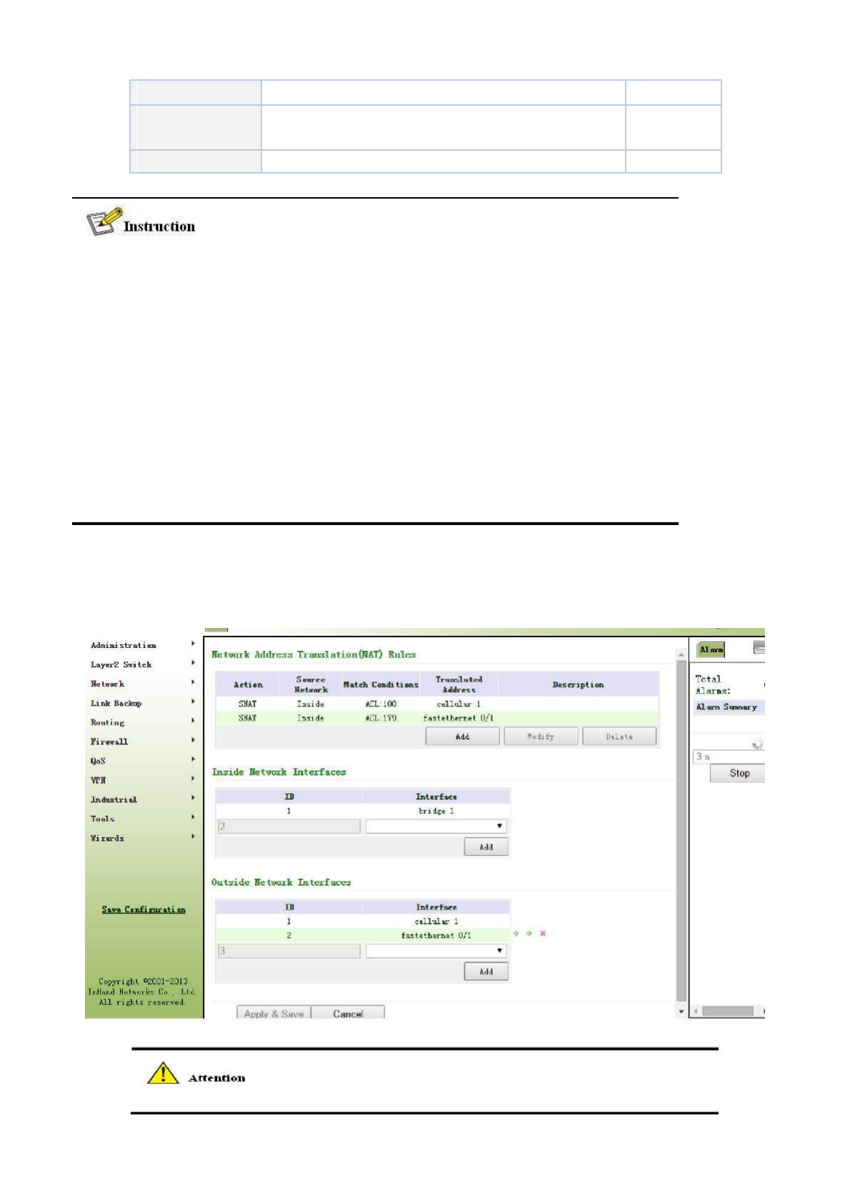
1:1NAT: Transfer IP address one to one.
Source Network
Inside:Inside address
Inside
Outside:Outside address
Translation Type
Select the Translation Type
IP to IP
Private network IP address refers to the IP address of internal network or host, while public
network IP address is a globally unique IP address on the Internet.
RFC 1918 three IP address blocks for the private network as follows:
Class A: 10.0.0.0 ~ 10.255.255.255
Class B: 172.16.0.0~ 172.31.255.255
Class A: 192.168.0.0~ 192.168.255.255
The addresses within the above three ranges will not be allocated on the Internet. Therefore, they
can be freely used in companies or enterprises without the need to make application to the
operator or registration center
3.6.2.1 NAT
Click navigation panel “Firewall>>NAT” menu, enter “NAT” interface, as shown in the following figure.
89
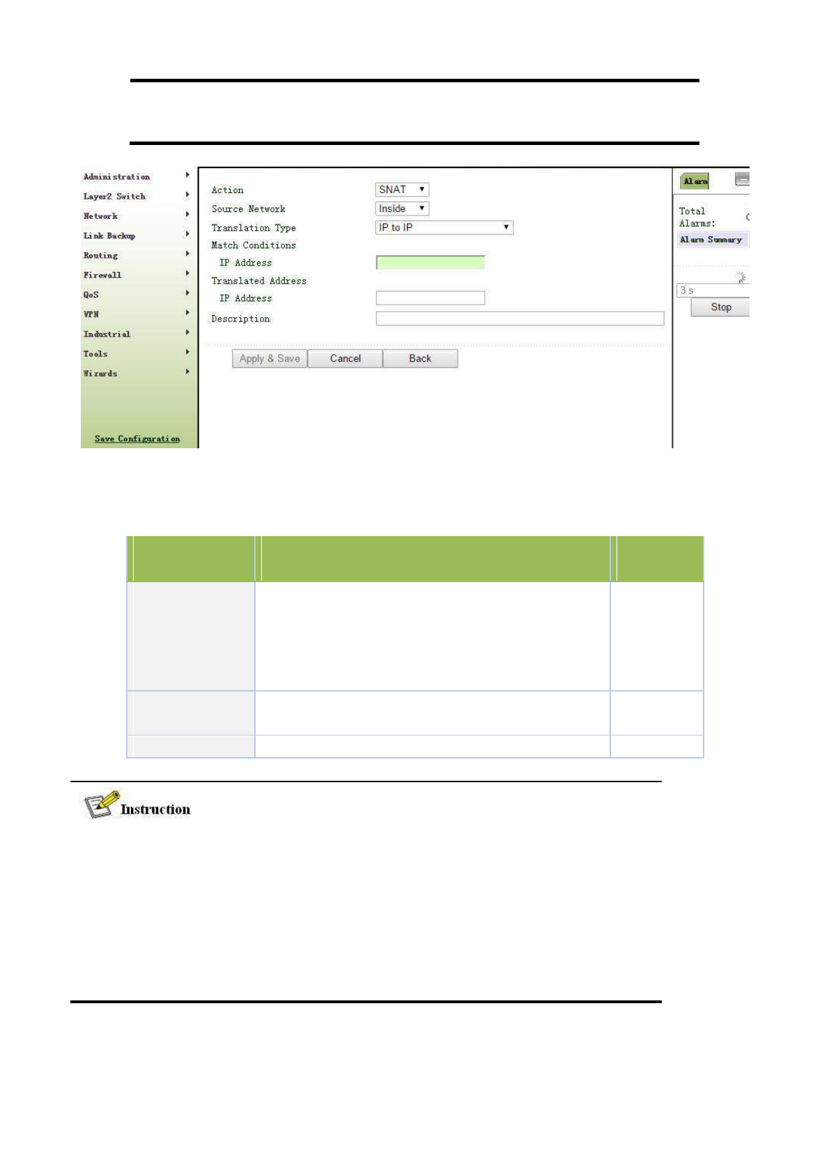
NAT rule is to apply ACL into address pool, and only address matched with ACL can be
translated.
Click <Add>, enter new configuration interface and add new NAT rules, as shown in the following figure.
Page information is shown below:
Parameter Name
Description
Default
Value
SNAT: Source address translation: to translate the source
address of IP data package to another address.
Action
DNAT: Destination address translation: to map a group of
SNAT
local home address to a group of legal global address.
1:1NAT: 1 to 1 translation of IP address
Source Network
Inside: home address
Inside
Outside: foreign address
Translation Type
Select the translation type of NAT
IP to IP
Private network IP address refers to the IP address of home network or mainframe, and IP address
of public network refers to the only global IP address on the internet. RFC 1918 reserves 3 IP
addresses for private network, as shown followed:
A: 10.0.0.0~10.255.255.255
B: 172.16.0.0~172.31.255.255
C: 192.168.0.0~192.168.255.255
The addresses in the three types above will not be distributed on the internet, so they can be used
in companies or enterprises instead of being applied to operator or registration center.
3.6.2.2 NAT Application Example
90
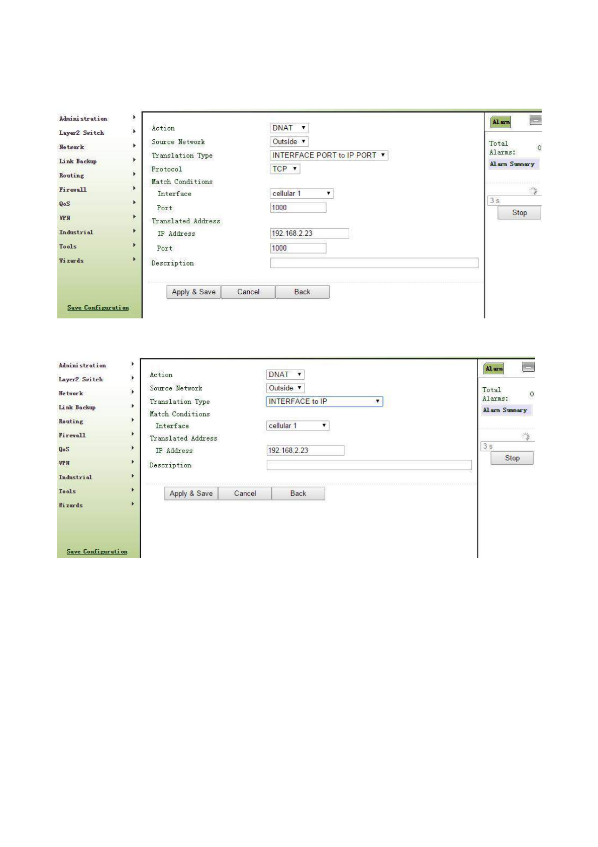
Example: a router TK8X5L has access to internet via dial-up; FE 0/2 is connected with a server whose IP address
is 192.168.2.23. Configure router to make public network have access to the server.
(Port mapping way) configuration of router is as follows:
(DMZ way) configuration of router is as follows:
3.7Qos
In the traditional IP network, all packets are treated equally without distinction. Each network
device uses first in first out strategy for packet processing. The best-effort network sends packets to
the destination, but it cannot guarantee transmission reliability and delay.
QoS can control network traffic, avoid and manage network congestion, and reduce packet
dropping rate. Some applications bring convenience to users, but they also take up a lot of network
bandwidth. To ensure all LAN users can normally get access to network resources, IP traffic control
function can limit the flow of specified host on local network.
QoS provides users with dedicated bandwidth and different service quality for different
applications, greatly improving the network service capabilities. Users can meet various requirements of
different applications like guaranteeing low latency of time-sensitive business and bandwidth of
91
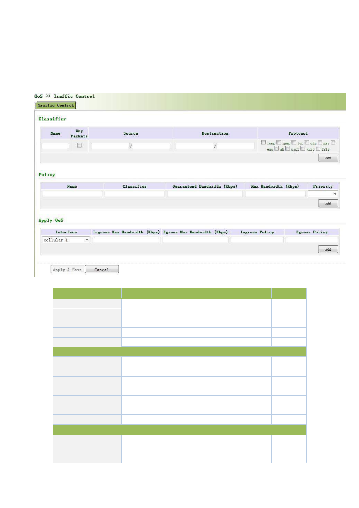
multimedia services.
QoS can guarantee high priority data frames receiving, accelerate high-priority data frame
transmission, and ensure that critical services are unaffected by network congestion. TK8X5L supports
four service levels, which can be identified by receiving port of data frame, Tag priority and IP priority.
From navigation panel, select Qos>>Traffic Control, then enter “Traffic Control” page,as
shown below.
Page description is shown below:
Parameters
Description
Default
Name
Name
Name
Any Packets
Click Startup for flow control to any packets
Forbidden
Source
Source address of flow control
N/A
Destination
Destination address of flow control
N/A
Protocol
Click to select protocol style
N/A
Policy
Name
Name of user defined flow control strategy
N/A
Classifier
Name of style defined above
N/A
Guaranteed
Bandwidth
User defined guaranteed bandwidth
N/A
Kbps
Maximum
Bandwidth
User defined maximum bandwidth
N/A
Kbps
Local Priority
Local priority of selection strategy
N/A
Apply Qos
Interface
Selection of flow control interface
cellular1
Ingress Max bandwidth
User define, bigger than maximum bandwidth of input
N/A
Kbps
strategy
92
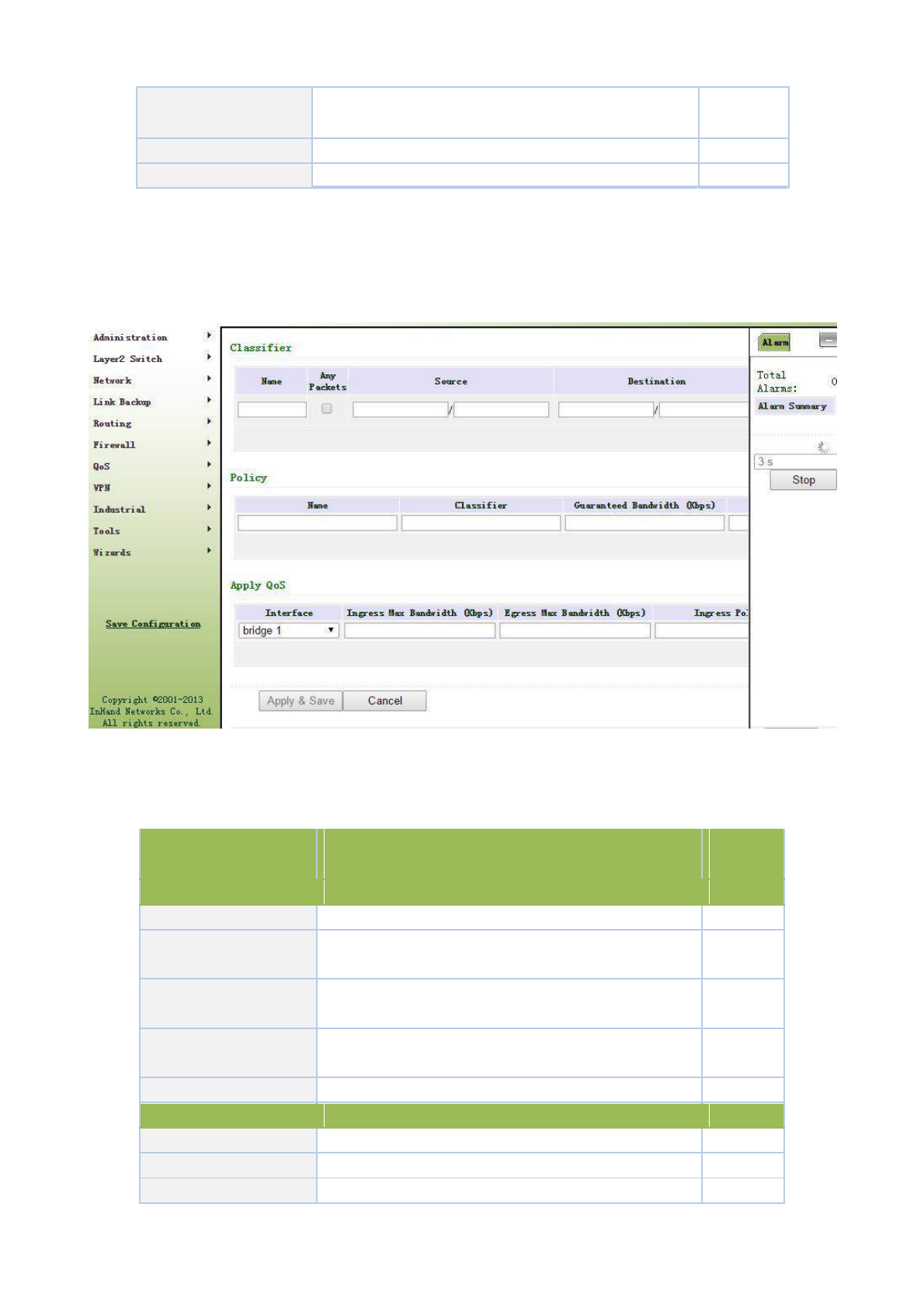
Egress Max bandwidth
User define, bigger than maximum bandwidth of output
N/A
Kbps
strategy
Ingress Policy
Name of policy defined above
N/A
Egress Policy
Name of policy defined above
N/A
3.7.1QoS
Click navigation panel “QoS>>flow control” menu, enter “flow control” interface, as shown in the following
figure.
Refer to Table 3-7-1 for page information.
Table 3-7-1 Parameter Description of Flow Control
Parameter Name
Description
Default
Value
Type
Name
Name of user self-defined flow control
No
Any Message
Click starting, control the flow of any message after
Forbidde
starting
n
Source Address
Source address of flow control (blank in case of any
No
configuration)
Destination Address
Destination address of flow control (blank in case of any
No
configuration)
Protocol
Click protocol type
No
Strategy
Name
Name of user self-defined flow control strategy
No
Type
Name of defined types above
No
Assured
Bandwidth
Assured bandwidth in user self-definition
No
93
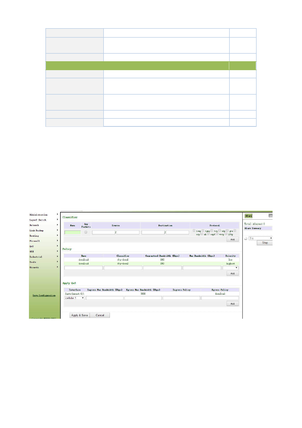
Kbps
Maximum
Bandwidth
Maximum bandwidth in user self-definition
No
Kbps
Local Preference
Local preference in selecting strategy
No
Application Qos
Port
Control port of selecting flow
cellular1
Maximum
Input
Maximum bandwidth more than input strategy in user
No
Bandwidth Kbps
self-definition
Maximum
Output
Maximum bandwidth more than output strategy in user
No
Bandwidth Kbps
self-definition
Input Strategy
Strategy name defined above
No
Output Strategy
Strategy name defined above
No
3.7.2 QoS Application Example
Example: Set router to distribute local preference to different downloading channels.
Configuration procedures of router are as follows:
Step 1: Add “type” to describe downloading flow, for example, the IP address of local mainframe appointed
shall be the destination.
Step 2: Add “strategy” to guarantee the bandwidth and local preference of each “type”.
Step 3: Select the out-port in strategy application and distribute a out maximum bandwidth for port, as shown
in the following figure.
3.8VPN
VPN is a new technology that rapidly developed in recent years with the extensive application
of Internet. It is for building a private dedicated network on a public network. 'Virtuality" mainly
refers to that the network is a logical network.
Two Basic Features of VPN:
94

Private: the resources of VPN are unavailable to unauthorized VPN users on the internet;
VPN can ensure and protect its internal information from external intrusion.
Virtual: the communication among VPN users is realized via public network which,
meanwhile can be used by unauthorized VPN users so that what VPN users obtained is
only a logistic private network. This public network is regarded as VPN Backbone.
Fundamental Principle of VPN
The fundamental principle of VPN indicates to enclose VPN message into tunnel with
tunneling technology and to establish a private data transmission channel utilizing VPN Backbone
so as to realize the transparent message transmission.
Tunneling technology encloses the other protocol message with one protocol. Also,
encapsulation protocol itself can be enclosed or carried by other encapsulation protocols. To the
users, tunnel is logical extension of PSTN/link of ISDN, which is similar to the operation of actual
physical link.
The common tunnel protocols include L2TP, PPTP, GRE, IPSec, MPLS, etc.
3.8.1IPSec
A majority of data contents are Plaintext Transmission on the Internet, which has many
potential dangers such as password and bank account information stolen and tampered, user identity
imitated, suffering from malicious network attack, etc. After disposal of IPSec on the network, it
can protect data transmission and reduce risk of information disclosure.
IPSec is a group of open network security protocol made by IETF, which can ensure the
security of data transmission between two parties on the Internet, reduce the risk of disclosure and
eavesdropping, guarantee data integrity and confidentiality as well as maintain security of service
transmission of users via data origin authentication, data encryption, data integrity and anti-replay
function on the IP level.
IPSec, including AH, ESP and IKE, can protect one and more date flows between hosts,
between host and gateway, and between gateways. The security protocols of AH and ESP can
ensure security and IKE is used for cipher code exchange.
IPSec can establish bidirectional Security Alliance on the IPSec peer pairs to form a secure
and interworking IPSec tunnel and to realize the secure transmission of data on the Internet.
3.8.1.1IPsec Phase 1
IKE can provide automatic negotiation cipher code exchange and establishment of SA for
IPSec to simplify the operation and management of IPSec. The self-protection mechanisms of IKE
can complete identity authentication and key distribution in an insecure network.
From navigation panel, select VPN>>IPSec, then enter “IPSec Phase 1” page,as shown below.
95

Page description is shown below:
Parameters
Description
Default
Keyring
Name
User define key
N/A
IP Address
End-to-end IP address
N/A
Subnet Mask
End-to-end subnet mask
N/A
Key
User define key content
N/A
Policy
Identification
Policy identification of user defined IKE
N/A
Authentication
Alternative authentication: shared key and digital certificate
Shared key
3des: encrypt plaintext with three DES cipher codes of 64bit
Encryption
des: encrypt a 64bit plaintext block with 64bit cipher code
3des
Aes: encrypt plaintext block with AES Algorithm with cipher code length of
128bit, 192bit or 256bit
md5: input information of arbitrary length to obtain 128bit message digest.
Hash
sha-1: input information with shorter length of bit to obtain 160bit message
md5
digest.
Comparing both, md5 is faster while sha-1 is safer.
Diffie-Hellman
Three options: Group 1, Group 2 and Group 5
Group 2
Key Exchange
Lifetime
Active time of policy
86400
ISAKMP Profile
Name
Name of user defined ISAKMP Profile
N/A
Main mode: as an exchange method of IKE, main mode shall be established
Negotiation Mode
in the situation where stricter identity protection is required.
Main mode
Aggressivemode: as an exchange method of IKE, aggressive mode
exchanging fewer message, can accelerate negotiation in the situation where
96
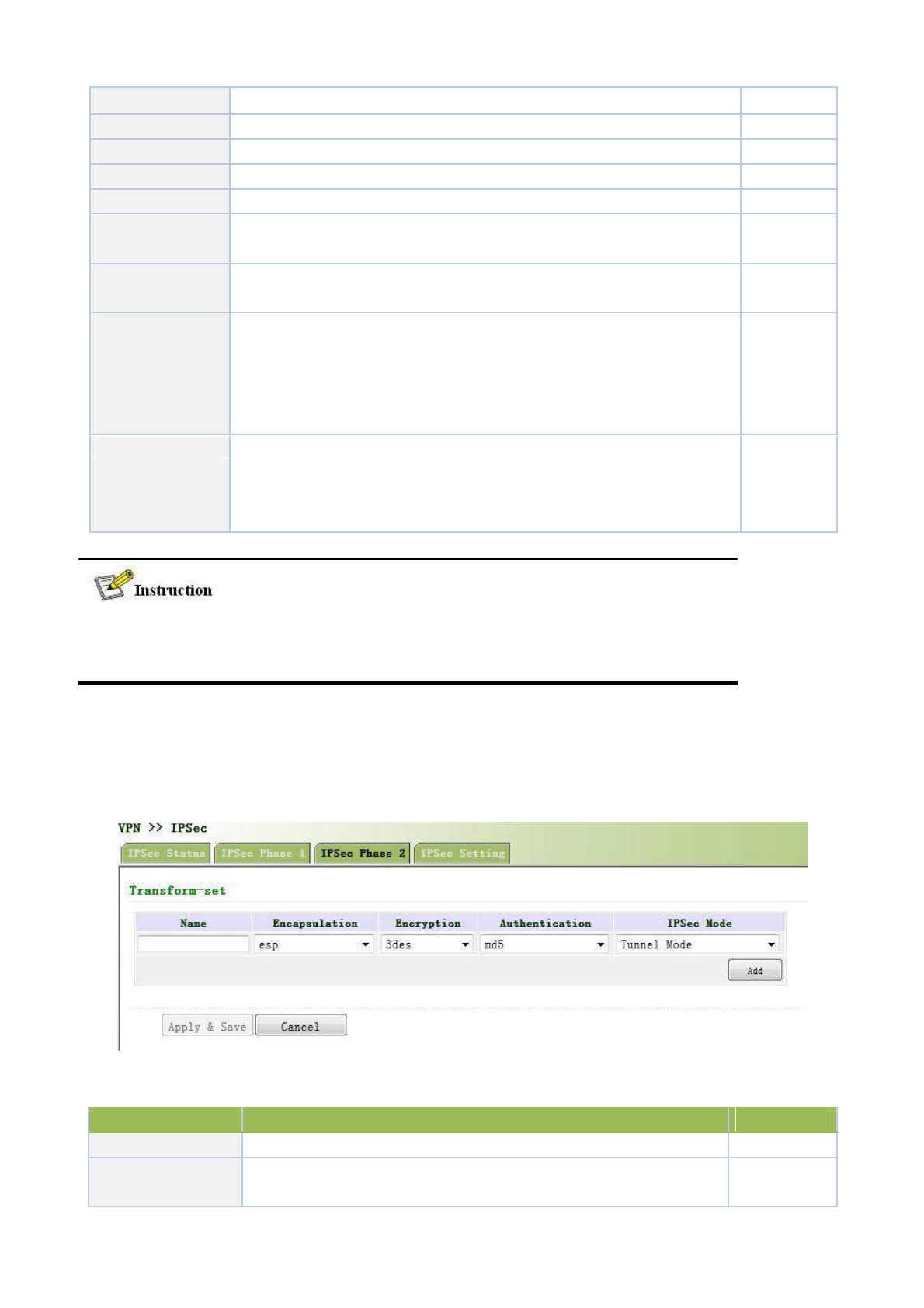
ordinary identity protection is required.
Local ID Type
Select type of local identification
IP Address
Local ID
The local ID corresponding to the selected local ID
N/A
Remote ID Type
Select type of Remote ID
IP Address
Remote ID
The Remote ID corresponding to the selected peer identification
N/A
Policy
The defined strategy identification in the IKE Strategy list
N/A
Key Ring
The defined key set in the key set list
N/A
Used for detection interval of IPSec neighbor state.
After initiating DPD, If receiving end can not receive IPSec cryptographic
DPD Interval
message sent by peer end within interval of triggering DPD, receiving end
N/A
can make DPD check, send request message to opposite end automatically,
detect whether IKE peer pair exists.
Receiving end will make DPD check and send request message
DPD Timeout
automatically to opposite end for check. If it does not receive IPSec
cryptographic message from peer end beyond timeout, ISAKMP Profile will
N/A
be deleted.
The security level of three encryption algorithms ranks successively: AES, 3DES, DES. The
implementation mechanism of encryption algorithm with stricter security is complex and
slow arithmetic speed. DES algorithm can satisfy the ordinary safety requirements.
3.8.1.2IPsec Phase 2
From navigation panel, select VPN>>IPSec, then enter “IPSec Phase 2” page,as shown below.
Page description is shown below:
Parameters
Description
Default
Name
User define Transform Set name
N/A
Encapsulation
Choose encapsulation forms of data packet
esp
AH: protect integrity and authenticity of data
packet from hacker
97
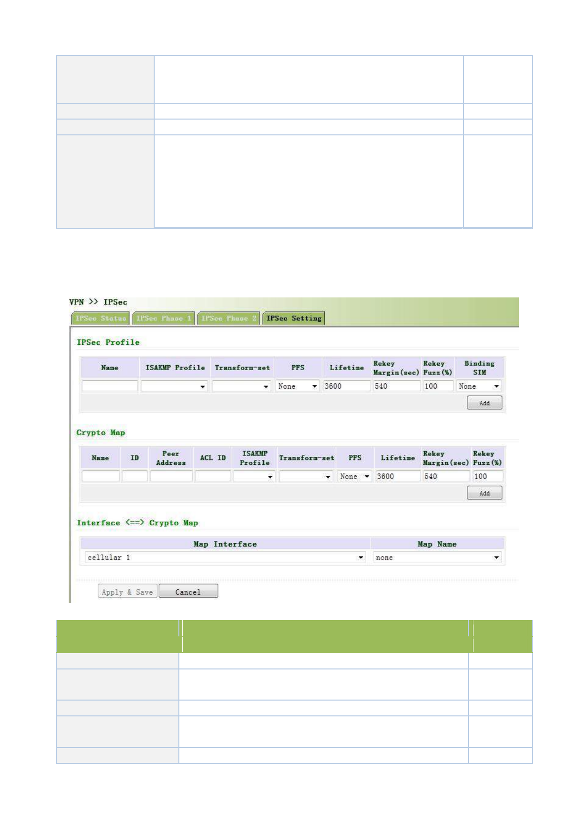
intercepting data packet or inserting false data packet on the internet.
ESP: encrypt the user data needing protection, and then enclose into IP
packet for the purpose of confidentiality of data.
Encryption
Three options: AES, 3DES, DES
3des
Authentication
Alternative authentication: md5 and sha-1
md5
Tunnel Mode: besides source host and destination host, special gateway
will be operated with password to ensure the safety from gateway to
IPSec Mode
gateway.
Tunnel Mode
TransmissionMode: source host and destination host must directly be
operated with all passwords for the purpose of higher work efficiency,
but comparing with tunnel mode the security will be inferior.
3.8.1.3IPsec configuration
From navigation panel, select VPN>>IPSec, then enter “IPSec Setting” page,as shown below.
Page description is shown below:
Parameters
Description
Default
IPSec Profile
Name
User define IPSecProfile name
N/A
ISAKMP Profile
ISAKMP Profile names defined in the first stage of parameters of
N/A
IPSec
Transform Set
Transform Set defined in the first stage of parameters of IPSec
N/A
Perfect Forward Security
Means the reveal of one cipher code will not endanger information
Forbidden
(PFS)
protected by other cipher codes.
Lifetime
Lifetime of IPSecProfile
N/A
98
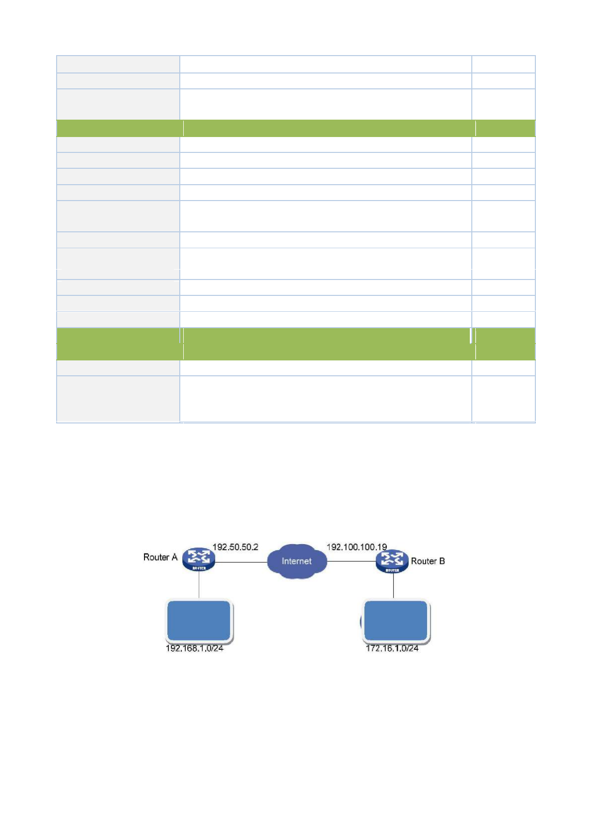
Rekey Margin (S)
Reconnection time for the second stage
N/A
Rekey Fuzz (%)
Deviation percentage of the reconnection time for the second stage
N/A
SIM Card Binding
With this function activated, successful dialing of the card with
Forbidden
which IPSec is bonded is a precondition for the use of IPSec.
Crypto Map
Name
User define name of crypto map
N/A
ID
User define ID of crypto map
N/A
Peer Address
Peer IP Address
N/A
ACL ID
ID of ACL defined in ACL of firewall
N/A
ISAKMP Profile
ISAKMP Profile names defined in the first stage of parameters of
N/A
IPSec
Transform Set
Transform Set defined in the first stage of parameters of IPSec
N/A
Perfect Forward Security
Means the reveal of one cipher code will not endanger information
Forbidden
(PFS)
protected by other cipher codes.
Lifetime
Validity of Crypto Map
N/A
Rekey Margin (S)
Reconnection time for the second stage
N/A
Rekey Fuzz (%)
Deviation percentage of the reconnection time for the second stage
N/A
Parameters
Description
Default
Interface <==> Crypto Map
MAP Interface
Select Interface Name
cellular1
Map Name
Select from defined names of Crypto Map. One name is matched
none
with several marks.
3.8.1.4 IPSec VPN Configuration Example
Building a secure channel between Router A and Router B to ensure the secure data flow between Customer
Branch A‘s subnet (192.168.1.0/24) and Customer Branch B‘s subnet (172.16.1.0/24). Security protocol is ESP,
the encryption algorithm is 3DES, and authentication algorithm is SHA.
The topology is as follows:
Customer Customer
Branch A Branch B
Configuration Steps:
(1) Router A Settings
Step 1: IPSec Setting Phase 1
From navigation panel, select VPN>>IPSec, then enter “IPSec Setting Phase 1” page,as shown below.
99
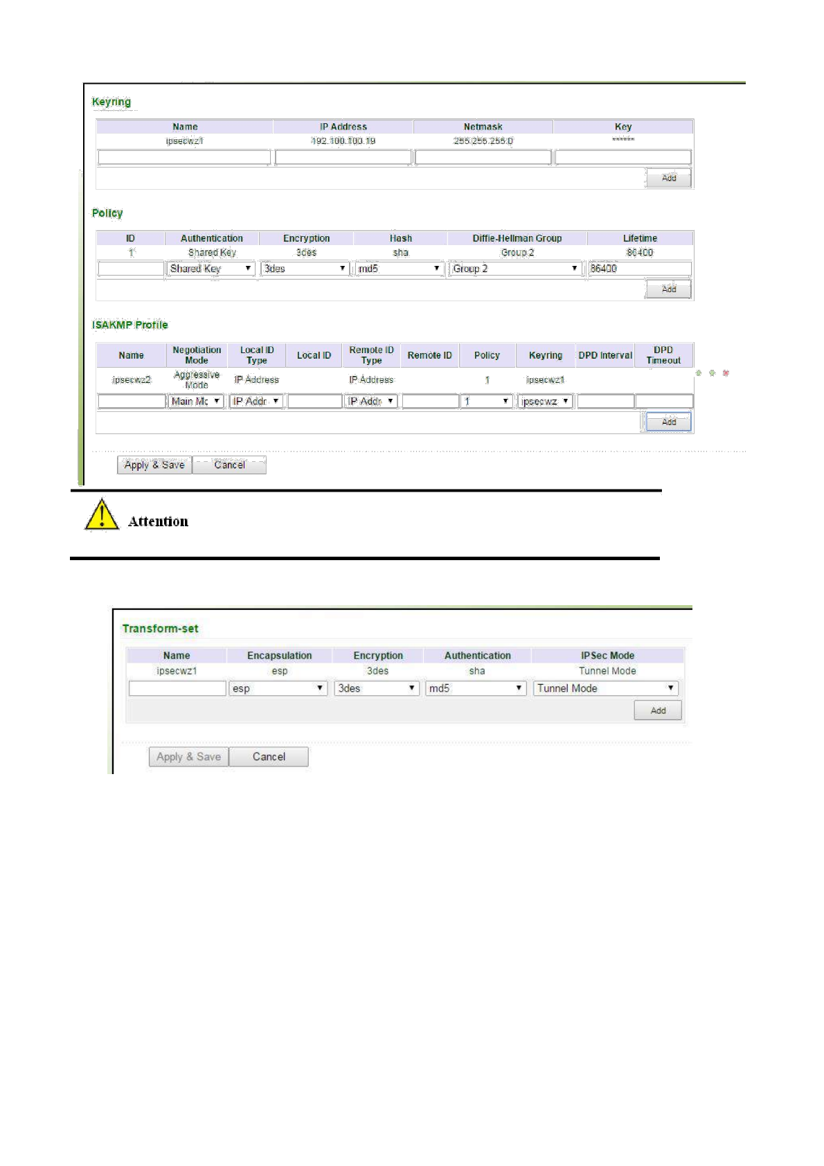
No need to fill in Local ID Type and Remote ID Type.
Step 2: IPSec Setting Phase 2
From navigation panel, select VPN>>IPSec, then enter “IPSec Setting Phase 2” page,as shown below.
Step 3: IPSec Setting
From navigation panel, select VPN>>IPSec, then enter “IPSec Setting” page,as shown below.
100
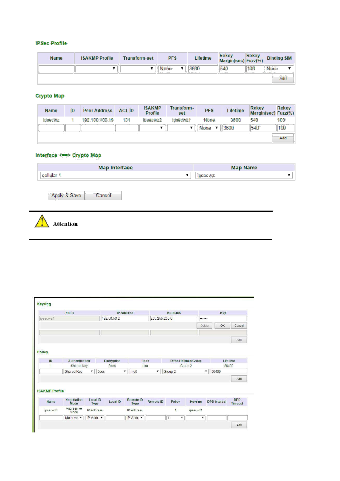
IPSec Profile setting is needed only when it’s DMVPN.
(2) Router B Settings
Step 1: IPSec Setting Phase 1
From navigation panel, select VPN>>IPSec, then enter “IPSec Setting Phase 1” page,as
shown below.
Step 2: IPSec Setting Phase 2
101
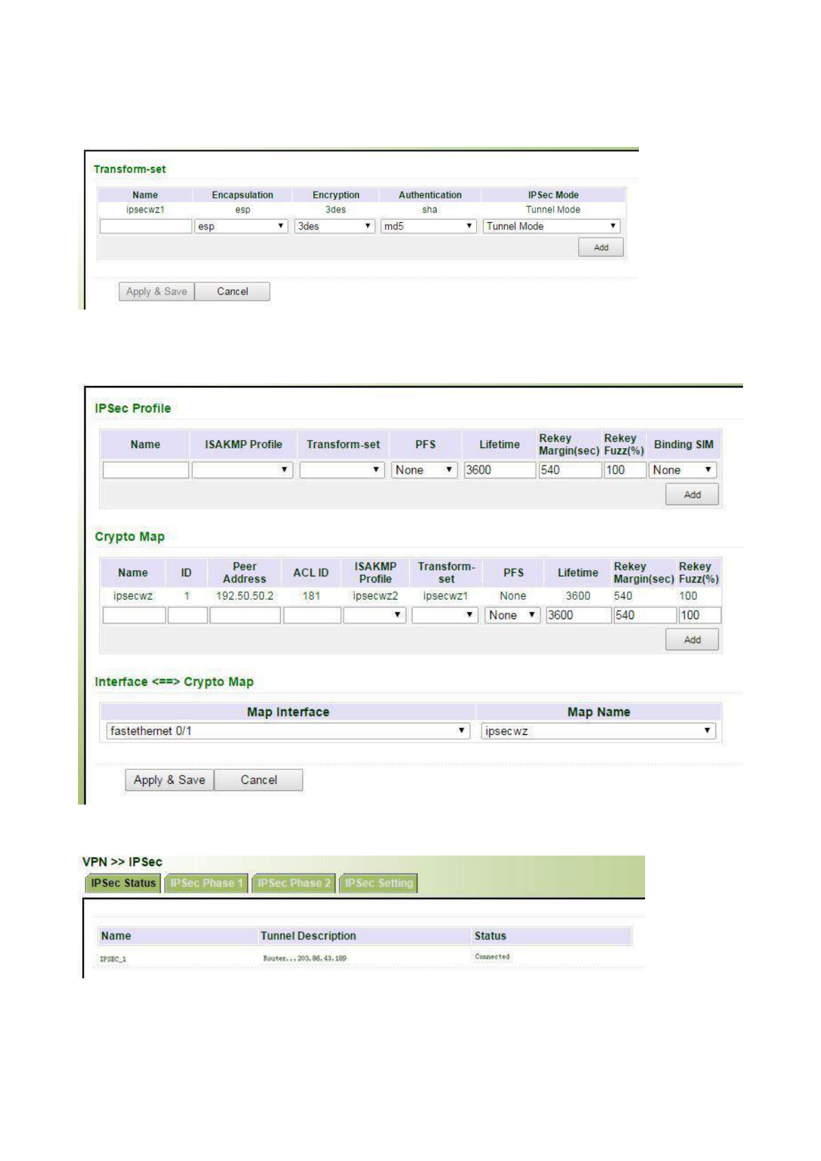
From navigation panel, select VPN>>IPSec, then enter “IPSec Setting Phase 2” page,as
shown below.
Step 3: IPSec Setting
From navigation panel, select VPN>>IPSec, then enter “IPSec Setting” page,as shown below.
(3) VPN Status Checking
From navigation panel, select VPN>>IPSec, then enter “IPSec Status” page,as shown below.
3.8.2GRE
Generic Route Encapsulation (GRE) defines the encapsulation of any other network layer
102

protocol on a network layer protocol. GRE could be used as the L3TP of VPN to provide a
transparent transmission channel for VPN data. In simple terms, GRE is a tunneling technology
which provides a channel through which encapsulated data message could be transmitted and
encapsulation and decapsulation could be realized at both ends. GRE tunnel application networking
shown as the following figure:
X
X
GRE
Along with the extensive application of IPv4, to have messages from some network layer
protocol transmitted on IPv4 network, those messages could by encapsulated by GRE to solve the
transmission problems between different networks.
In following circumstances GRE tunnel transmission:
GRE tunnel could transmit multicast data packets as if it were a true network interface. Single
use of IPSec can not achieve the encryption of multicast.
A certain protocol adopted can not be routed.
A network of different IP address shall be required to connect other two similar networks.
GRE application example: combined with IPSec to protect multicast data
GRE can encapsulate and transmit multicast data in GRE tunnel, but IPSec, currently, could
only carry out encryption protection against unicast data. In case of multicast data requiring to be
transmitted in IPSec tunnel, a GRE tunnel could be established first for GRE encapsulation of
multicast data and then IPSec encryption of encapsulated message so as to achieve the encryption
transmission of multicast data in IPSec tunnel.
From navigation panel, select VPN>>GRE, then enter “GRE” page,as shown below.
103
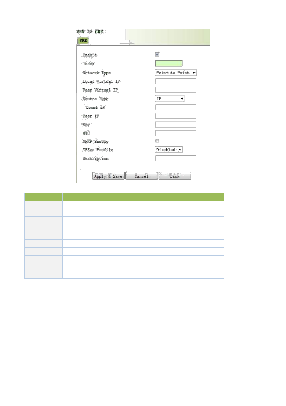
Page description is shown below:
Parameters
Description
Default
Enable
Click to open
Open
Index
Set GRE tunnel name
None
Network Type
Select GRE network type
点对点
Local Virtual IP
Set Local Virtual IP Address
None
Peer Virtual IP
Set Peer Virtual IP Address
None
Source Type
Select source type and set the according IP address or interface
IP
Local IP
Set Local IP Address
None
Peer IP
Set Peer IP Address
None
Key
Set the key of tunnel
None
Description
Add description
None
3.8.3 DMVPN
3.8.3.1DMVPN Introduction
VPN is a combination of MGRE, NHRP and IPSec, shortened as DMVPN. It could provide a low cast safe
interconnection plan based on Internet for enterprises and companies with a large number of branches in many cities. Its
backbone network adopts Hub and Spoke. Dynamic tunneling is allowed to be established between different branches
for data transmission. When two branches are in the same city but the center is in another, data could be directly
transmitted between the two branches to reduce delay and consumption of central router, being much more economical;
adding of branches will not change the configuration of the center and other branches while maintenance work is
reduced exponentially; branch node could use dynamic IP address for saving IP address
104

resource in public network; dynamic tunnel is featured by a large network scale. Those advantages make it extremely
suitable for the safe interconnection of enterprises and companies with a large number of branches in many cities.
3.8.3.2 DMVPN Solution
DMVPN is achieved through the combination of multi-point GRE (mGRE) and Next Hop
Resolution Protocol (NHRP).
In DMVPN solution, IPSec is used to achieve encryption, GRE or multi-point GRE (mGRE) is
used to create a tunnel, and NHRP is used to resolve the problem of dynamic address. DMVPN
only requires that the center nodes must apply for a static public IP address.
Next Hop Resolution Protocol (NHRP) is defined in RFC 2332 by the IETF. It is used to obtain
the interconnected network layer address and NBMA subnetwork address for reaching the “next
hop” of destination nodes for the source node (host or router) on the non-broadcast multiple access
(NBMA) network.
Automatic Starting of IPSec Encryption
be encrypted. It means that when there is a data package matching the defined ACL, the IPSec
encryption tunnel will be created. When GRE Over IPSec is used, GRE tunnel configuration has
included the address of GRE tunnel’s opposite end. This address is also on the address of the
opposite terminal of IPSec tunnel. Therefore, it is unnecessary to separately define matching ACL
for IPSec. Through binding GRE tunneling with IPSec, once the GRE tunnel is established, IPSec
encryption will be immediately triggered.
Dynamic Tunnel Establishment of Spoke-to-Hub
In DMVPN network, there is no branch GRE or IPSec configuration information on the center
router, while it is required to configure GRE tunnel according to the external network’s public IP
address and NHRP protocol of the center router. When the branch router is energized and started up,
the IP address can be obtained through DHCP at ISP, and an IPSec encrypted GRE tunnel can be
automatically established and the IP address of external port can be registered at the center router
through NHRP. There are reasons in three aspects:
1) Since the IP address of branch router’s external network port is automatically obtained, the IP
address may be different every time. Therefore, the center router can not be configured based
on the address information.
2) The center router is not required to configure GRE or IPSec information for all branches, which
will greatly simplify the configuration of the center router. All relevant information can be
automatically obtained through NHRP.
3) In case of DMVPN network expansion, it is not required to change the configuration of the center
router and other branch routers. The new branch routers will be automatically registered in the
center router. Through the dynamic routing protocol, all other branch routers can learn this new
routing and the new branch routers can also learn the routing information to reach all other routers.
Dynamic Tunnel Establishment of Spoke−to−Spoke
105

In DMVPN network, the Spoke−to−Hub tunnel, once established, will persist, while it is not
required to directly configure a continuous tunnel between branches. When a branch wants to
transmit data package to another branch, it will use NHRP to dynamically acquire the IP address of
destination branch. In this process, the center router acts as the NHRP server to respond to the
request of NHRP and provide the public network address of destination branch to the source branch.
Hence, an IPSec tunnel can be dynamically established between two branches through the mGRE
port for data transmission. The tunnel will be automatically removed after a predefined cycle.
Support for Dynamic Routing Protocols
DMVPN is based on GRE tunnel, while GRE tunnel supports the transmission of multicast or
broadcast IP packet in tunnel. Therefore, DMVPN network supports running dynamic routing
protocols on IPSec and mGRE tunnels. It should be pointed out that NHRP must be configured as
dynamic multicast mapping, so that when the branch router registers unicast mapped address on the
NHRP server (center router), NHRP will also establish a multicast / broadcast mapping for the
branch router.
We have mentioned above that IPSec tunnel does not support multicast / broadcast packet
encapsulation, while GRE tunnel encapsulates multicast / broadcast packet in GRE packet, and
GRE packet is a unicast packet and can be encrypted by IPSec. In encryption of GRE packet with
IPSec, IPSec can be configured to the transmission mode, because GRE has encapsulated the
original packet as the unicast IP packet and it is unnecessary to let IPSec re-encapsulate a header.
The transmission mode IPSec requires that the source and destination addresses of encrypted
data packet must match with the addresses of the IPSec tunnel’s both terminals. It means that the
addresses of the GRE tunnel’s both terminals must be the same with those of the IPSec tunnel’s
both terminals. Since the routers on both terminals of GRE tunnel are the same routers on both
terminals of IPSec tunnel, so this can be guaranteed.
Through the combination of GRE tunnel and IPSec encryption, we can utilize the dynamic
routing protocol to update the routing tables on the routers at both ends of the encrypted tunnel. The
subnet learned from the tunnel peer will contain the IP address of tunnel’s opposite terminal as the
next hop address of the opposite terminal’s subnet. So that, in case of change in the network at any
terminal of tunnel, the other end will dynamically learn this change and maintain the connectivity of
network without changing the configuration of router.
3.8.3.3 Realization of Dynamic Routing Protocol in DMVPN Network
We have mentioned above that in the DMVPN network, the Spoke−to−Hub tunnel, once
established, will persist, while there is no persistent tunnel between branches. So that, after the
initialization of router, the center router will announce the reachable routings of other branch
subnets to branch routers through the persistent tunnel. Therefore, the "next hop" address reaching
other branch subnet in the branch router's routing table will be the address of center router’s tunnel
port instead of the address of other branch router’s tunnel port. Thus, the data transmission between
branches will still pass through the center router.
106

To solve this problem, it is required to set on the center router. When a branch subnet’s
reachable routing is announced on the port of mGRE tunnel, the "next hop" address is the address of
this branch router’s tunnel port instead of the address of the center router.
In RIP or EIGRP equidistant vector routing protocol, the function of split horizon is usually
achieved, to prevent sending the routing information back to its source port and avoid routing loop on
the adjacent routers. If RIP or EIGRP protocol runs on the DMVPN network, it is required to turn off
the split horizon function. Otherwise, the branch routers will not be able to learn the routing to the other
branch subnets. For RIP, this is enough, because when RIP sends the routing to the routing information
source port, its "next hop" address will not be changed and remains to be the original address. When
EIGRP sends the routing to the routing information source port, its "next hop" address will change to
the address of the port. Therefore, it is necessary to turn off this feature (EIGRP is private protocol of
CISCO. The IOS command to turn off this feature is no ip next-hop-self eigrp).
OSPF is a link status type routing protocol and itself does not have the problem of split horizon.
However, in configuring OSPF network type, it is required to be configured as a broadcast rather
than the point-to-multipoint type. Otherwise, the above problems will be caused. In addition, it
should also be noted that it is required to configure the center router (Hub) of DMVPN as the
designated router (DR) of OSPF, which can be achieved by specifying a higher OSPF priority for
the center router (Hub).
3.8.3.4 DMVPN Configuration Example
Topology
Networking Environment
1) R1: Must have a fixed and public IP address (as HUB);
2) R2/R3/R4: Dial-up, dynamically get public IP address (as Spoke);
3) Establish DMVPN between R2/R3/R4 and HUB, make all the LANs can access each other;
4) Related to the points: GRE tunnel/NHRP/Dynamical routing/IPsec VP
1. Configuration
(1) Settings of R2/R3/R4
Step 1: Configure IPsec
Navigate to “VPN>>IPsec”, enter the page “IPsec Phase 1”, configuration is shown below:
107
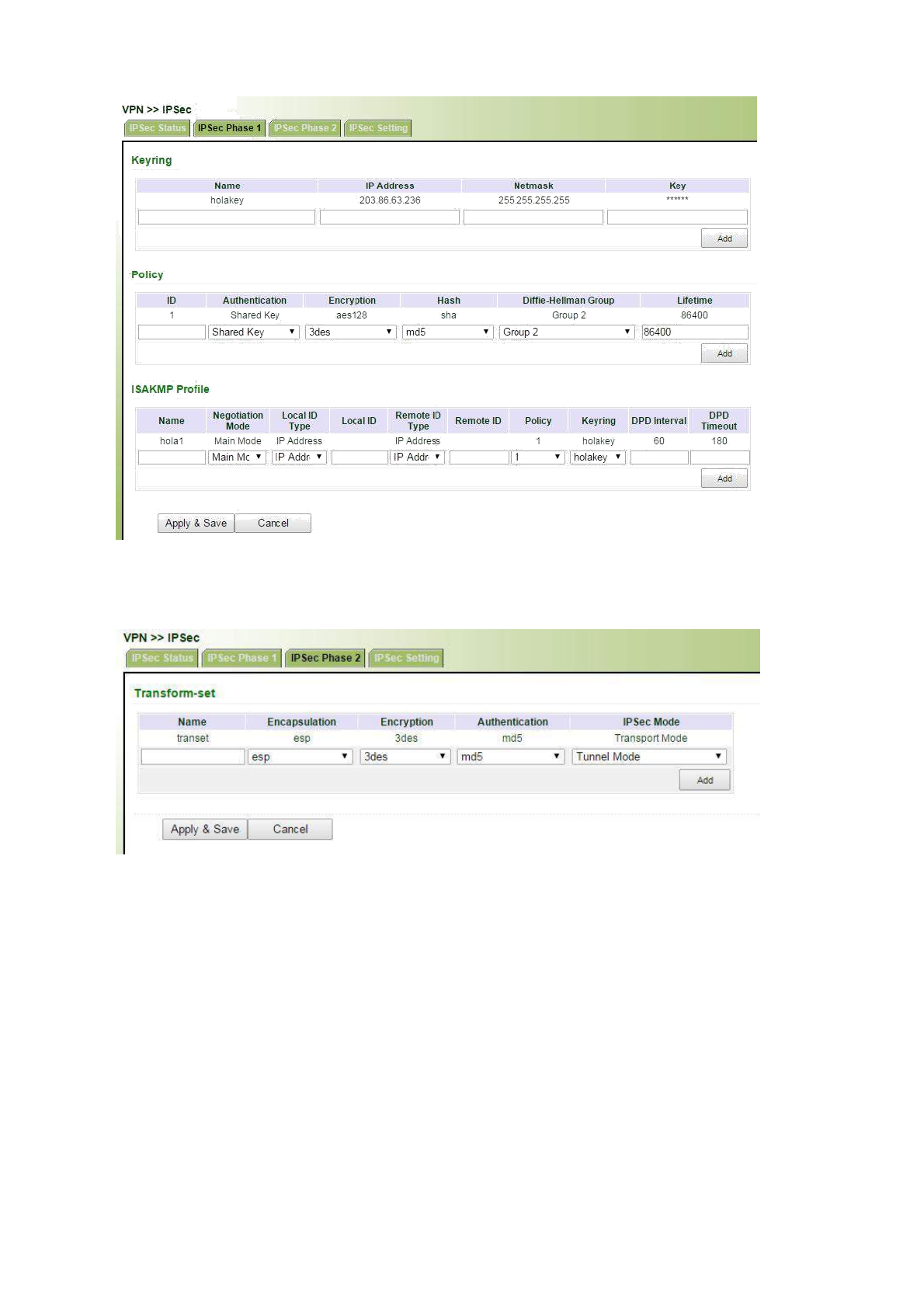
Navigate to “VPN>>IPsec”, enter the page “IPsec Phase 2”, configuration is shown below:
Navigate to “VPN>>IPsec”, enter the page “IPsec Setting”, configuration is shown below:
108
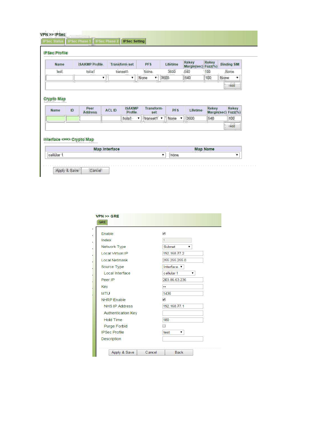
Step 2: Configure GRE
Navigate to “VPN>>GRE”, enter the “GRE” page, click on “Add”, configuration is shown below:
Step 3: Configure RIP
109
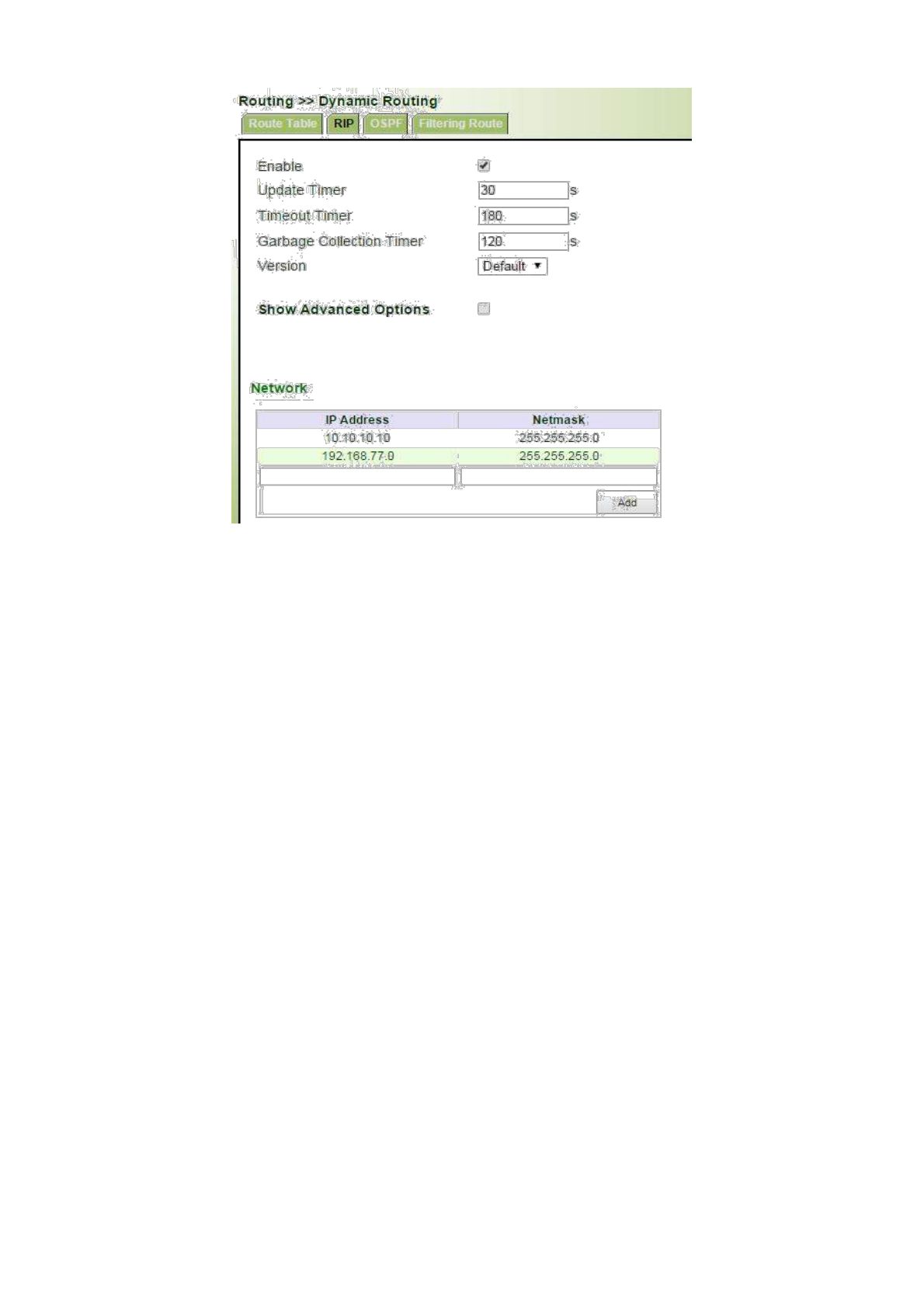
(2) Settings of R1 (Hub)
Step 1: Configure IPsec VPN
crypto isakmp policy
1 encr aes
authentication pre-
share group 2
crypto isakmp key hola address 0.0.0.0
0.0.0.0 crypto isakmp keepalive 60
crypto ipsec security-association lifetime seconds 86400
crypto ipsec transform-set ESP_3DES_MD5 esp-3des esp-md5-
hmac mode transport
crypto ipsec profile abc
set security-association lifetime seconds
3600 set transform-set ESP_3DES_MD5
Step 2: Configure GRE and NHRP
interface Tunnel1
ip address 192.168.77.1
255.255.255.0 ip mtu 1436
ip nhrp map multicast dynamic
ip nhrp network-id 10
ip nhrp holdtime 180
no ip split-horizon
110

tunnel source FastEthernet0/1
tunnel mode gre multipoint
tunnel key 123456
tunnel protection ipsec profile abc
Step 3: Configure Dynamical Routing
HUB(config)#router rip
HUB(config-router)#network192.168.0.1 255.255.255.0
HUB(config-router)#network192.168.77.1255.255.255.0
For now TK8X5L can only be used as the Spoke for the DMVPN
3.8.4L2TP
L2TP, one of VPDN TPs, has expanded the applications of PPP, known as a very important VPN technology
for remote dial-in user to access the network of enterprise headquarters.
L2TP, through dial-up network (PSTN/ISDN), based on negotiation of PPP, could establish a tunnel between
enterprise branches and enterprise headquarters so that remote user has access to the network of enterprise
headquarters. PPPoE is applicable in L2TP. Through the connection of Ethernet and Internet, a L2TP tunnel
between remote mobile officers and enterprise headquarters could be established.
L2TP-Layer 2 Tunnel Protocol, encapsulates private data from user network at the head of L2 PPP. No
encryption mechanism is available, thus IPSes is required to ensure safety.
Main Purpose: branches in other places and employees on a business trip could access to the network of
enterprise headquarter through a virtual tunnel by public network remotely.
VPN →L2TP →L2TP Client
From navigation panel, select VPN>>L2TP, then enter “L2TP Client” page,as shown below.
111
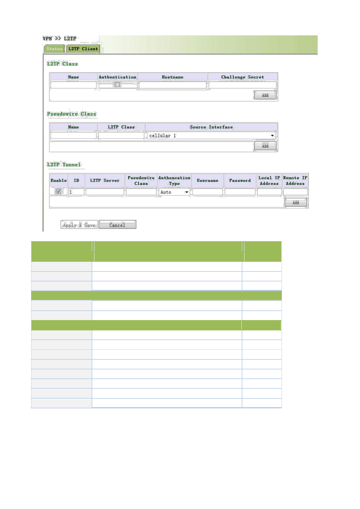
Page description is shown below:
Parameters
Description
Default
L2TP Class
Name
L2TP class name
None
Host Name
Local host name
None
Challenge Secret
Set challenge secret
None
Pseudowire Class
Name
User define Pseudowire Class name
None
Source Interface
Select source interface name
cellular 1
L2TP Tunnel
Enable
Click to enable
Enable
L2TP Server
Set L2TP Server address
None
Pseudowire Class
Pseudowire Class name
None
Authentication Type
Select Authentication Type
Auto
Username
Peer Server username
None
Password
Peer Server password
None
Local IP Address
Set local IP address
None
Set remote IP address
Remote IP Address
None
3.8.5OPENVPN
Single point participating in the establishment of VPN is allowed to carry out ID verification by preset
private key, third-party certificate or username/password. OpenSSL encryption library and SSLv3/TLSv1 protocol
are massively used.
112
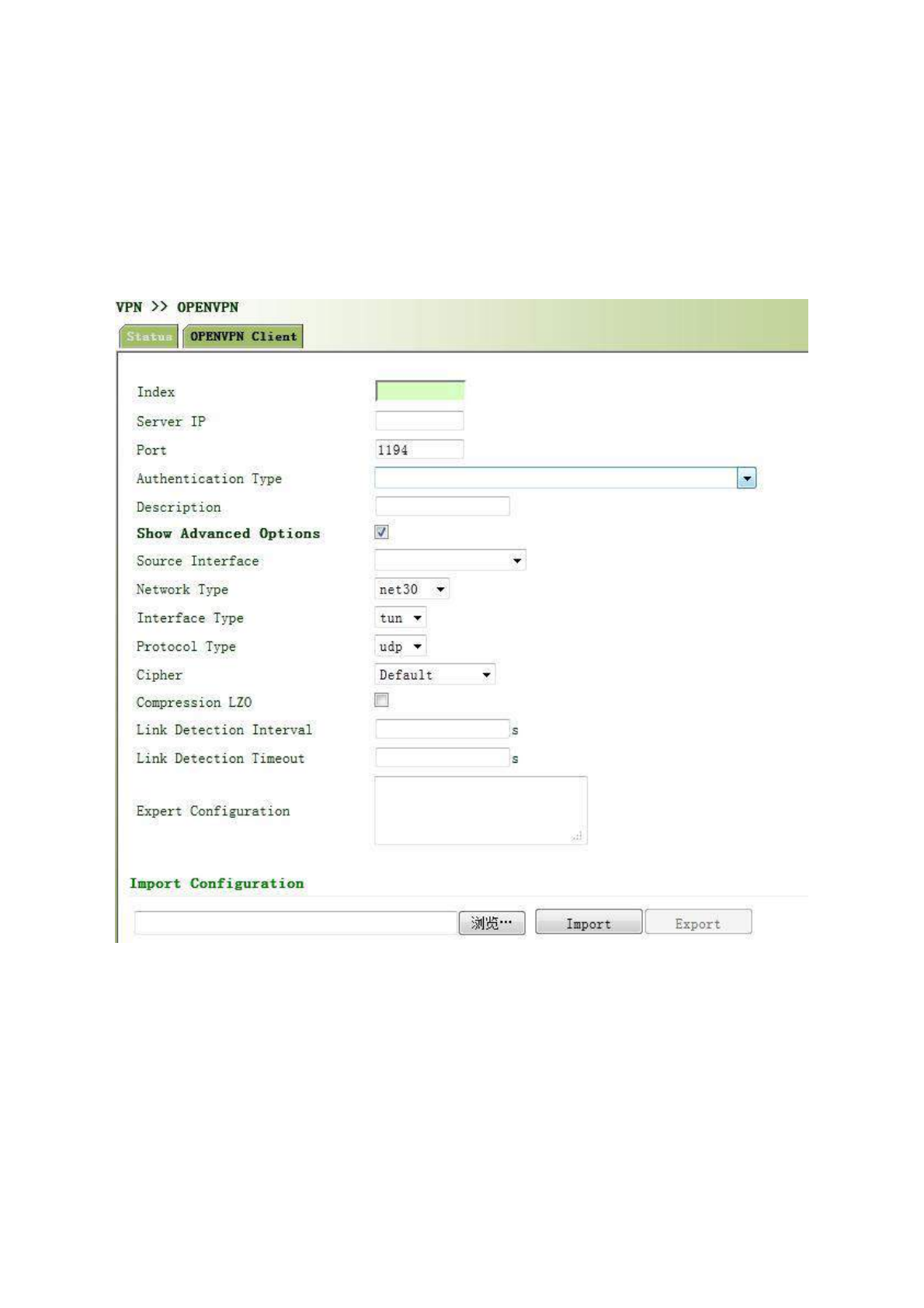
In OpenVpn, if a user needs to access to a remote virtual address (address family matching virtual network
card), then OS will send the data packet (TUN mode) or data frame (TAP mode) to the visual network card
through routing mechanism. Upon the reception, service program will receive and process those data and send
them out through outer net by SOCKET, owing to which, the remote service program will receive those data and
carry out processing, then send them to the virtual network card, then application software receive and accomplish
a complete unidirectional transmission, vice versa.
From navigation panel, select VPN>>OPENVPN, then enter “OPENVPN Client” page,as
shown below.
3.8.5.1 OPENVPN
Click navigation panel “VPN>>OPENVPN” menu, enter “OPENVPN customer end” menu, as shown in the
following figure.
113

Refer to Table 3-8-5-1 for page information.
Table 3-8-5-1 Parameter Description of OPENVPN Customer End
Parameter Name
Description
Default Value
Starting
Click starting
Starting
ID
Set channel ID
No
Server IP Address
Fill in IP address of backend server
No
Port Number
Fill in port number of backend server
1194
Certification Type
Select certification type and configure corresponding
User
parameters of certification type
name/Password
User Name
Keep consistency with server
No
Password
Keep consistency with server
No
Channel Description
Content described in user’s self-defined channel
No
Advanced Options
Source Port
Select name of source port
No
Network Type
Select type of network
Net30
Port Type
Select the data form sending out from the port. tun-data
Tun
package, tap-data frame
Protocol Type
Protocol in server communication and keep
udp
consistency with server protocol
Advanced Options
Encryption Algorithm
Keep consistency with server
Default
LZO Compression
Click starting
Closed
Connection
Testing
Set connecting testing time interval
No
Interval
Connection
Testing
Set connecting testing overtime
No
114
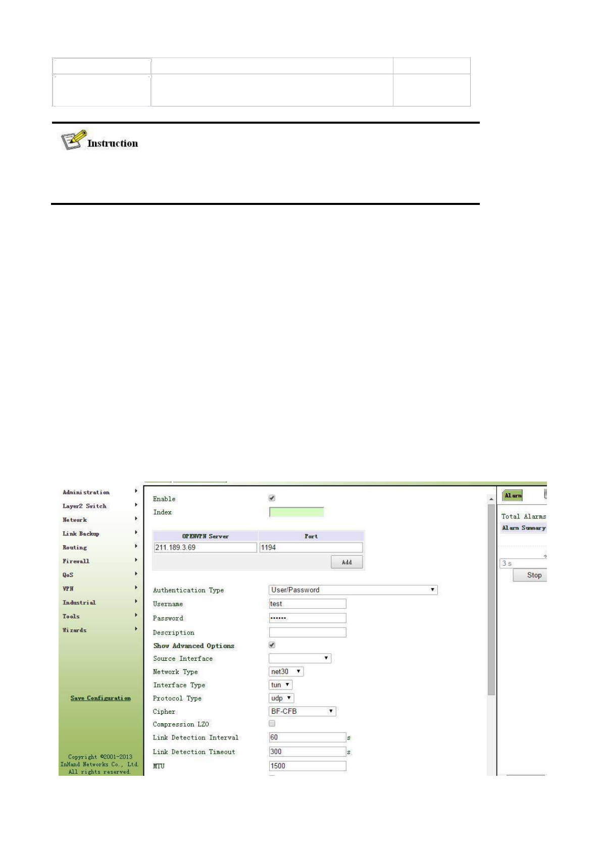
Overtime
Expert Set expert option: blank advisable No
Configuration
Import configurations can be directly imported into the configured documents generated from
backend server and manual configuration of OPENVPN customer end parameter is in no need
after import.
3.8.5.2 OPENVPN Application Example
Example: OpenVPN is based on TCP/UDP and can be applied to any port. Refer to the following figure for
topological graph.
In the figure, an OpenVPN channel is established on equipment A and OpenVPN server. The virtual IPs at
both sides of the channel are respectively 192.168.5.2 and 192.168.5.1.
a. If OpenVPN of equipment A is in routing mode, the routing to 192.168.8.0/24 will be to OpenVPN channel and
OpenVPN server. Accordingly, a static routing will be added to OpenVPN server so that the packet routing to
192.168.9.0/24 will be to OpenVPN channel. In this way, PC A and PC B is intercommunicated via OpenVPN
and two-way visit can be realized.
b. if OpenVPN is in NAT mode via equipment A, OpenVPN server is in no need to increase the static routing
about 192.168.9.0/24. Now, PC A can have access into PC B, but PC B cannot directly have access into PC A.
It is applied to initial uploading.
Configuration procedures of router are as follows:
Step 1: Configure relevant parameters of OpenVPN, as shown in the following figure.
115
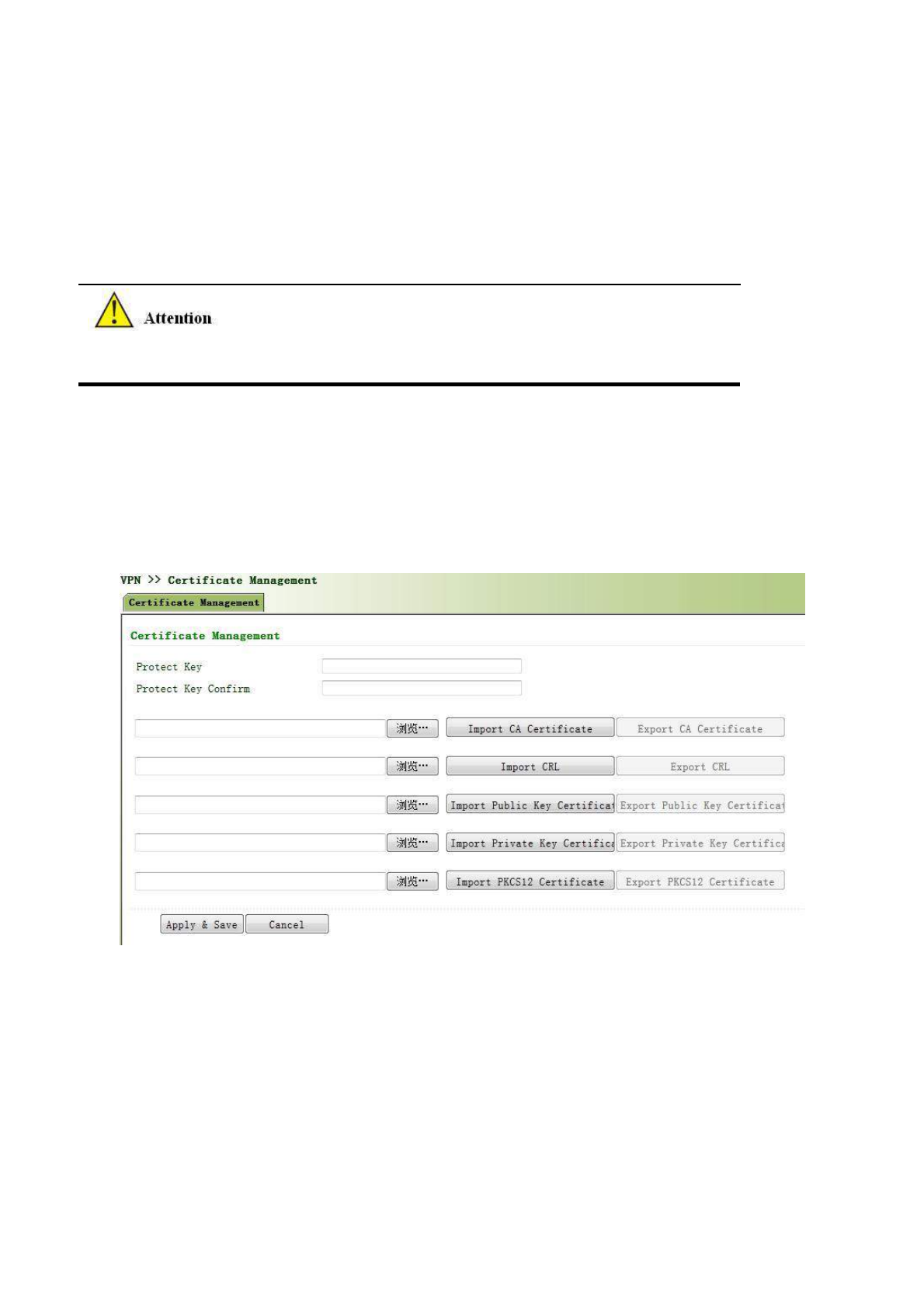
Step 2: Configure different certificates in accordance with different certification demand when the channel is
successfully established. The type of certification and certificate are as follows:
None ------
in no need of certificate
Pre-shared Key -----
in no need of certificate
User/Password -----
only CA certificate like ca.crt
X.509 Cert (multi-client), X.509 Cert -----
in need of CA certificate, equipment public key certificate,
equipment private key certificate like ca.crt, my.crt, my.key.
1. The suffix of CA and public key certificate is .crt and the suffix of private key certificate is .key.
2. The time of equipment must be accurate in using certificate.
Step 3: Configure OpenVPN server after router is configured. Add a static routing to 192.168.2.0/24, route
add -net 192.168.2.0 netmask 255.255.255.0 dev tun0 (suppose the net port of OpenVPN server is tun0).
3.8.6 Certificate Management
From navigation panel, select VPN>>Certificate Management, then enter “Certificate
Management” page,as shown below.
3.9 Industrial
Router’s industrial interface has two types: serial port and IO interface. Serial port has RS232
and RS485 modes and IO interface has digital input and relay output modes.
RS232 adopts full-duplex communication with one transmission line, one receiving line and
one ground line. RS232 is generally used for communication within 20m.
RS485 adopts half-duplex communication to achieve long-distance transmission of serial
communication data. RS485 is used for communication from tens of meters to kilometers.
Digital input of IO interface can convert electrical signals into binary digital control signals. The
116
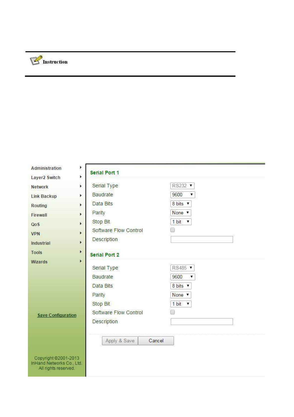
digital is a logical variable or switch variable with only two values 0 and 1. Low voltage
corresponds to the "0" and high voltage to "1"
IO’s relay output functions as an "auto switch" to automatically adjust protect and switch circuit.
This part only applies to TK8X5L with industrial interface.
3.9.1 DTU
3.9.1.1 Serial Port Settings
Setting the parameters of router’s serial port according to the serial port of the terminal device
connected with router to achieve the normal communication between router and terminal device.
From navigation panel, select Industrial >>DTU, then enter “DTU” page,as shown below.
117

Page description is shown below:
Parameters
Description
Default
Serial Type
Serial Port 1 is RS232, Serial Port 2 is RS485; cannot be
RS232/RS485
changed
Baudrate
Same with the baudrate of connected terminal device
9600
Data Bit
Same with the data bit of connected terminal device
8 bits
Parity
Same with the parity of connected terminal device
None
Stop Bit
Same with the stop bit of connected terminal device
1 bits
Software Flow
Click to enable
Off
Control
Description
User define
None
The parameters of router’s serial port must be the same with that of terminal
device connected.
3.9.1.2 DTU 1
From navigation panel, select Industrial >>DTU, then enter “DTU 1” page,as shown below.
118
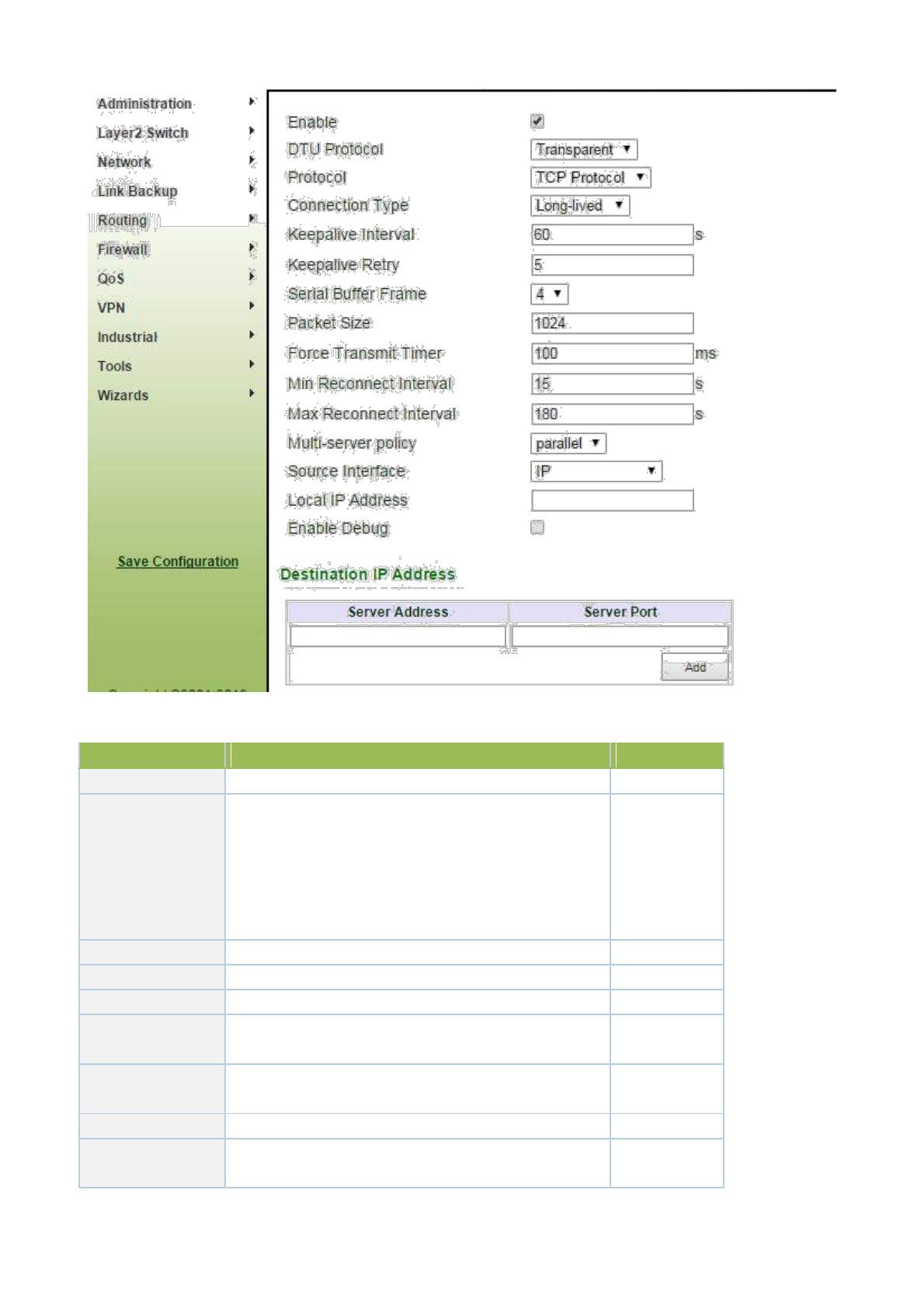
Page description is shown below:
Parameters
Description
Default
Enable
Click to enable
Off
Transparent and TCP: router used as client when
Transparent choosed, router used as server when TCP
DTU Protocol
choosed.
Transparent
RFC2217: no need to configure serial port
IEC101-104: for power industry, similar with TCP in
function
Protocol
TCP or UDP
TCP
Connection Type
Long-lived or Short-lived
Long-lived
Keepalive Interval
User define
60
Keepalive Retry
User define, TOP connection is off when reaching retry
5
limit
Serial
Buffer
User define
4
Frame
Pacaket Size
User define
1024
Force
Transmit
User define
100
Timer
119

Parameters
Description
Default
Min
Reconnect
User define
15
Interval
Max
Reconnect
User define
180
Interval
Parallel: connect the center of destination IP address list
at the same time
Multi-server Policy
Polling: connect to the first address in the list, if connect
Parallel
fail, continue to connect next address until connect one
successfully, then stop.
Source Interface
4 options; No need to choose
IP
Local IP Address
The device’s IP when source interface select “IP”.No
None
need to configure
Enable Debug
Click to enable
Off
Destination IP Address
Server Address
User define
None
Server Port
User define
None
Destination IP Addresses maximum 10.
DTU 2 configuration is same with DTU 1.
3.9.2 IO
Relay output is off by default and it can be turned on/off manually. The disconnect time can be
set manually and after reaching the set parameters relay output is automatically turned off.
From navigation panel, select Industrial>>IO, then enter “Status” page,as shown below.
120

Page description is shown below:
Parameters
Description
Default
Digital Input 1
Digital Input 1
Vlotage under 10Vcorrespond to LOW (0)
LOW (0)
Vlotage above 10Vcorrespond to High (1)
Relay Output
Relay Output 1
Off by default. Can be turned on manually, otherwise it is
Off
remains off.
Off: Click to turn on
Action
On: Click to turn on
Off time:
Off->On: user define off time, after off time, it turns on
1000ms
automatically.
3.10 Tools
3.10.1PING
From navigation panel, select Tools>>Ping, then enter “Ping” page,as shown below.
121

Page description is shown below:
Parameters
Description
Default
Host
It requires the destination host address of PING
192.168.2.1
detection
Ping Count
Set Ping detection count
4
Packet Size
Set packet size of ping detection
32 bytes
Expert Options
Advanced parameters of ping can be used
3.10.2 Routing detection
It is used to detect network routing failure.
From navigation panel, select Tools>>Traceroute, then enter “Traceroute” page,as shown
below.
122
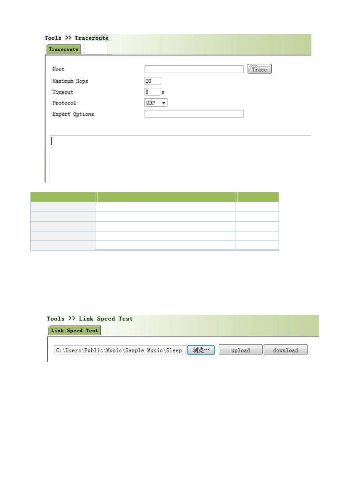
Page description is shown below:
Parameters
Description
Default
Host
Host address needs to detect
192.168.2.1
Maxium Hops
Set the maxium hops of routing detection
20
Timeout
Set timeout of routing detection
3 secs
Protocol
Select ICMP/UDP
UDP
Expert Options
Advanced parameters of ping can be used
3.10.3 Link Speed Test
Through upload and download files, link speed can be tested.
From navigation panel, select Tools>>Link Speed Test, then enter “Link Speed Test”
page,as shown below.
3.11 Configuration Wizard
Simplified normal configuration allows the rapid, simple and basic configuration of router, but can not
display the results of configuration which can be checked in corresponding configuration details previously upon
the accomplishment.
3.11.1 New LAN
123
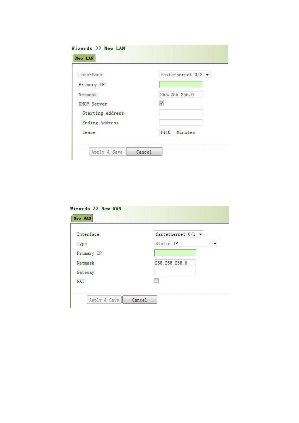
From navigation panel, select Wizards>>New LAN, then enter “New LAN” page,as shown
below.
3.11.2 New WAN
From navigation panel, select Wizards>>New WAN, then enter “New WAN” page,as shown
below.
3.11.3 New Cellular
From navigation panel, select Wizards>>New Cellular, then enter “New Cellular” page,as
shown below.
124
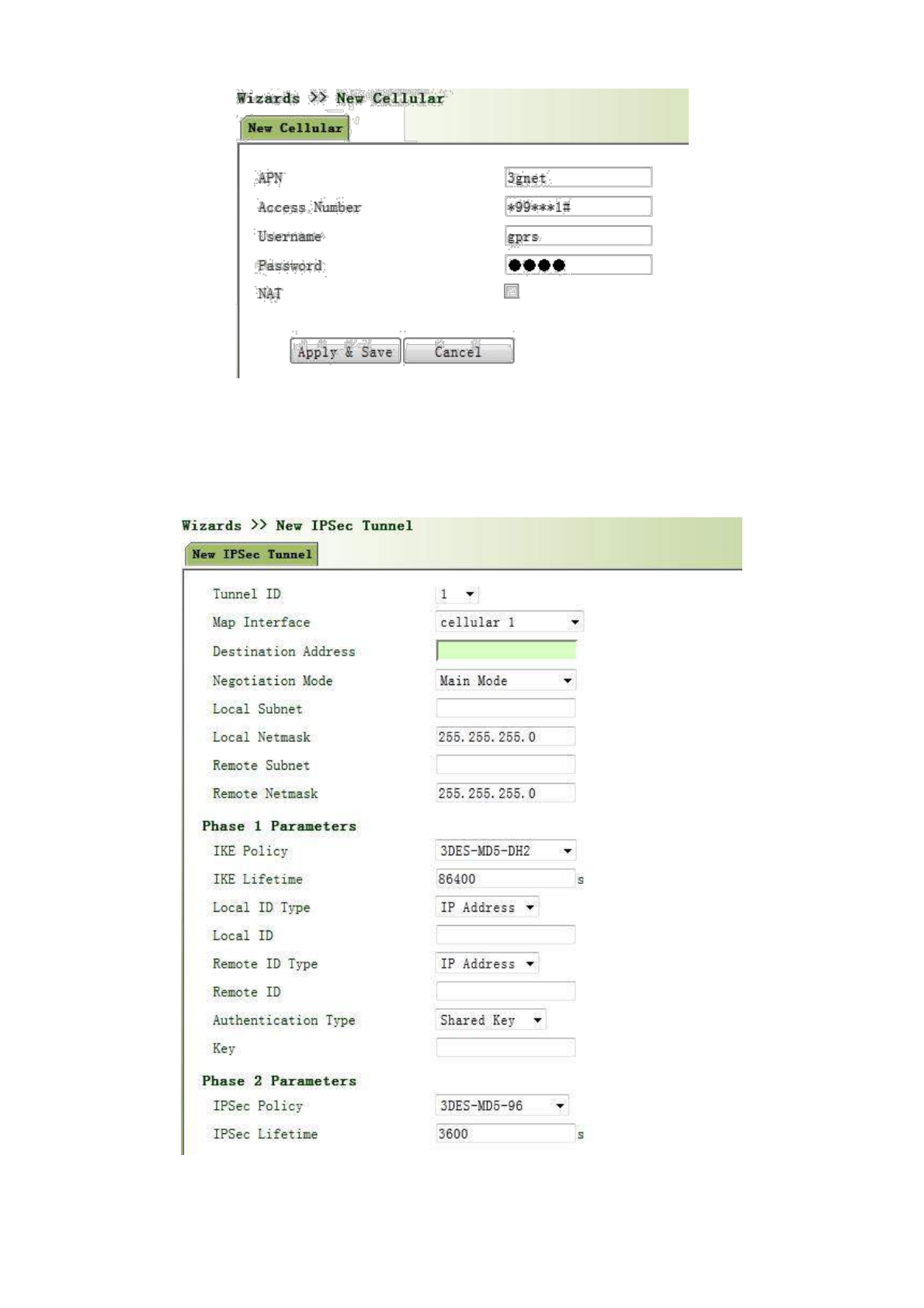
3.11.4 New IPSec Tunnel
From navigation panel, select Wizards>>New IPSec Tunnel, then enter “New IPSec
Tunnel” page,as shown below.
125
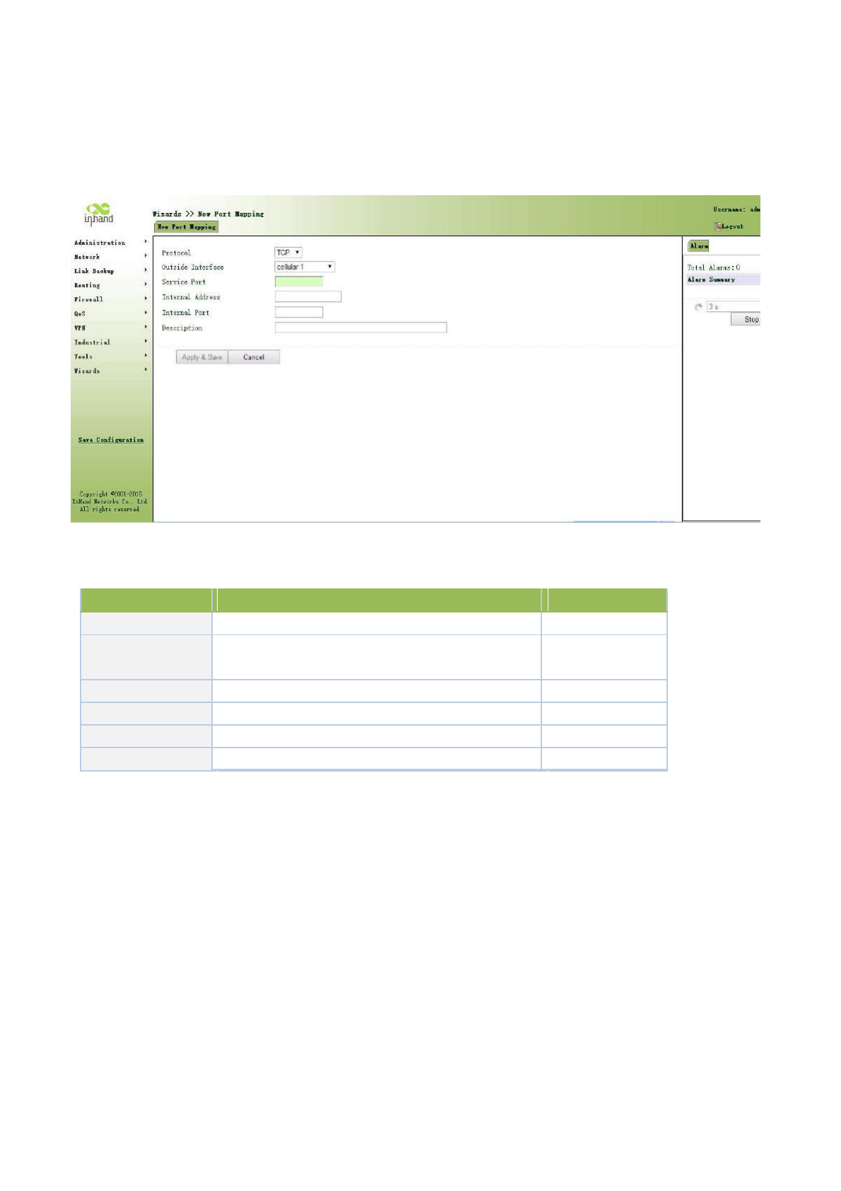
3.11.5 New Port Mapping
Click navigation panel “Wizard>>New Port Mapping” menu, enter “New Port Mapping” interface, as
shown below:
Page information is shown below:
Parameter Name
Description
Default
Protocol
TCP or UDP for protocol
TCP
Outside Interface
Users select port connecting outer net according to
Cellular 1
the demand
Service Port
TCP or UDP data communication port
None
Internal Address
Equipment address of mapping object
None
Internal Port
TCP or UDP port of mapping object
None
Description
User define
None
3.12 Network Mode
3.12.1 Cellular
The default network mode is via cellular. Connect the antenna and insert the SIM card to access internet.
3.12.2 ADSL Dialup (PPPoE)
Example: Choose ADSL Dialup (PPPoE) instead of Cellular.
Configuration procedures of router are as follows:
Step 1: Disable cellular as shown below.
126
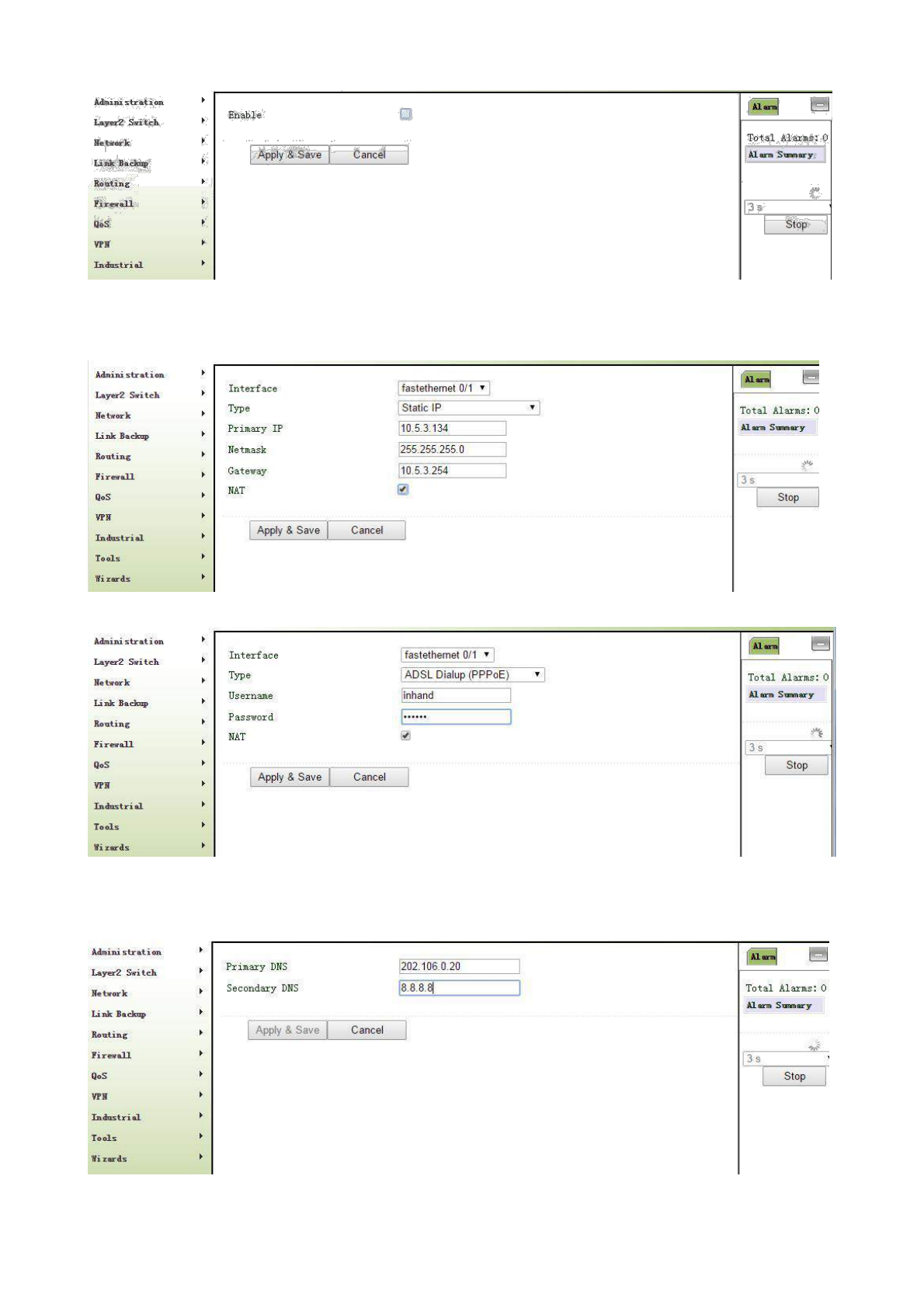
Step 2: Establish WAN, which is divided into three types, static IP type and ADSL dial-up (PPPoE) are
respectively shown in Fig. 3-12-2 and Fig. 3-12-3.
Fig. 3-12-2
Fig. 3-12-3
Step 3: Configure corresponding parameters of DNS service in case that static IP type is applied in the step
above, as shown below. Confirm the normal internet access of PC after configuration.
127

Appendix 1 Troubleshooting
1. TK8X5L is powered on, but can not access Internet?
Please check:
Whether the TK8X5L is inserted with a SIM card.
Whether the SIM card is enabled with data service, whether the service of the SIM card is suspended because of
an overdue charge.
Whether the dialup parameters, e.g. APN, dialup number, account, and password are correctly configured.
Whether the IP Address of your computer is the same subnet with TK8X5L and the gateway address is TK8X5L
LAN address.
2. TK8X5L is powered on, have a ping to detect TK8X5L from your PC and find packet loss?
Please check if the network crossover cable is in good condition.
3. Forget the setting after revising IP address and cannot configure TK8X5L?
Method 1: connect TK8X5L with serial cable, configure it through console port.
128

Method 2: within 5 seconds after TK8X5L is powered on, press and hold the Restore button until the ERROR
LED flashes, then release the button and the ERROR LED should goes off, press and hold the button again until
the ERROR LED blinks 6 times, the TK8X5L is now restored to factory default settings. You may configure it
now.
4. After TK8X5L is powered on, it frequently auto restarts. Why does this happen?
Please check:
Whether the module works normally.
Whether the TK8X5L is inserted with a SIM card.
Whether the SIM card is enabled with data service, whether the service of the SIM card is suspended because of
an overdue charge.
Whether the dialup parameters, e.g. APN, dialup number, account, and password are correctly configured.
Whether the signal is normal.
Whether the power supply voltage is normal.
5. Why does upgrading the firmware of my TK8X5L always fail?
Please check:
When upgrading locally, check if the local PC and TK8X5L are in the same network
segment. When upgrading remotely, please first make sure the TK8X5L can access Internet.
6. After TK8X5L establishes VPN with the VPN server, your PC under TK8X5L can connect to the
server, but the center cannot connect to your PC under TK8X5L?
Please make sure the firewall of your computer is disabled.
7. After TK8X5L establishes VPN with the VPN server, Your PC cannot connect to the server?
Please make sure “Shared Connection” on “Network=>WAN” or “Network=>Dialup” is enabled in the
configuration of TK8X5L.
8. TK8X5L is powered on, but the Power LED is not on?
Check if the protective tube is burn out.
Check the power supply voltage range and if the positive and negative electrodes are correctly connected.
9. TK8X5L is powered on, but the Network LED is not on when connected to PC?
When the PC and TK8X5L are connected with a network cable, please check whether a network crossover cable
is used.
Check if the network cable is in good condition.
Please set the network card of the PC to 10/100M and full duplex.
10. TK8X5L is powered on, when connected with PC, the Network LED is normal but cannot have a ping
detection to the TK8X5L?
Check if the IP Address of the PC and TK8X5L are in the same subnet and the gateway address is TK8X5L LAN
address.
11. TK8X5L is powered on, but cannot configure through the web interface?
Whether the IP Address of your computer is the same subnet with TK8X5L and the gateway address is TK8X5L
LAN address.
Check the firewall settings of the PC used to configure TK8X5L, whether this function is shielded by the firewall.
12. The TK8X5L dialup always fails, I cannot find out why?
Please restore TK8X5L to factory default settings and configure the parameters again.
13. How to restore TK8X5L to factory default settings?
- TK8X5L routers:
1. Press and hold the Restore button, power on TK8X5L;
2. Release the button until after the STATUS LED flashes and the ERROR LED is on;
3. After the button is released, the ERROR LED will go off, within 30s press and hold the Restore button again
until the ERROR LED flashes;

129

4. Release the button, the system is now successfully restored to factory default settings.
Appendix 2 Instruction of Command Line
1 Help Command
Help command can be obtained after entering help or “?” into console, “?” can be entered at any time during
the process of command input to obtain the current command or help from command parameters, and command or
parameters can be automatically complemented in case of only command or command parameter.
1.1 help
[Command] help [<cmd>] [Function]
get help from command [View] all
views [Parameter]<cmd> command
name
[Example]
enter: help
Get the list of all current available command.
130

enter: help show
Display all the parameters of show command and using instructions thereof.
2 View Switchover Command
2.1 enable
[Command] enable [15 [<password>]]
[Function] Switchover to privileged user level.
[View] Ordinary user view.
[Parameter]15 User right limit level, only supports right limit 15 (super users) at current. <password>
Password corresponded to privileged user limit level, hint of password inputting will be
given in case of no entering.
[Example] Enterenable adm in ordinary user view
Switchover to super users and the password 123456
2.2 disable
[Command] disable
[Function] Exit the privileged user level.
[View] Super user view, configure view
[Parameter] No
[Example] Enter disable in super user view
Return to ordinary user view.
2.3 end and !
[Command]end or !
[Function] Exit the current view and return to the last view.
[View] Configure view.
[Parameter] No
[Example] Enter end in configured view
Return to super user view.
2.4 exit
[Command]exit
[Function] Exit the current view and return to the last view (exit console in case that it is ordinary user)
[View] all views
[Parameter] No
[Example]
enter exit in configured view
Return to super user view.
enter exit in ordinary user
view Exit console.
3 Check system state command
3.1 show version
[Command] show version
[Function] Display the type and version of software of
router [View] all views
[Parameter] No
[Example] enter: show version
Display the following information:
Type : display the current factory type of equipment
Serial number : display the current factory serial number of equipment
131

Description : www.welotec.com
Current version : display the current version of equipment
Current version of Bootloader: display the current version of equipment
3.2 show system
[Command] show system
[Function] display the information of router
system [View] all views
[Parameter] No
[Example] enter: show system
Display the following information
Example: 00:00:38 up 0 min, load average: 0.00, 0.00, 0.00
3.3 show clock
[Command] show clock
[Function] display the system time of
router [View] all views
[Parameter] No
[Example] enter: show clock
Display the following information:
For example Sat Jan 1 00:01:28 UTC 2000
3.4 show modem
[Command] show modem
[Function] Display the MODEM state of router
[View] all views
[Parameter] No
[Example] Enter: show modem
Display the following information:
Modem type
state
manufacturer
product name
signal level
register state
IMSI number
Internet state
3.5 show log
[Command] show log [lines <n>]
[Function] display the log of router system and display the latest 100 logs in default.
[View] all views
[Parameter]lines <n> limits the log numbers displayed, wherein, n indicates the latest n logs in case that it is
positive integer and indicates the earliest n logs in case that it is negative integer and indicates all the logs
in case that it is 0.
[Example] enter: show log
Display the latest 100 log records.
3.6 show users
[Command] show users
[Function] display the user list of router.
132

[View] all views
[Parameter] No
[Example] input: show users
Displayed user list of system is as follows:
User:
-------------------------------------------------
* adm
------
Wherein, user marked with * is super user.
3.7 show startup-config
[Command]show startup-config
[Function] Display the starting device of router.
[View] super user view and configuration view
[Parameter] No
[Example] enter: show startup-config
Display the starting configuration of system.
3.8 show running-config
[Command] show running-config
[Function] display the operational configuration of router
[View] super user view, configuration view
[Parameter] No
[Example] Enter: show running-config
Display the operational configuration of system.
4 Check the Command of Internet State
4.1 show interface
[Command] show interface
[Function] Display the information of port state of
router [View] all views
[Parameter] No
[Example]enter: show interface
Display the state of all ports.
4.2show route [Command]
Show ip route
[Function] Display the routing list of
router [View] all views
[Parameter] No
[Example] enter: Show ip route
Display the routing list of
system 4.3 show arp
[Command] show arp
[Function] Display the ARP list of
router [View] all views
[Parameter] No
[Example] enter: show arp
Display the ARP list of system
133

5 Internet Testing Command
Router has provided ping, telnet and traceroute for internet testing.
5.1 ping
[Command]ping <hostname> [count <n>] [size <n>] [source <ip>]
[Function] apply ICMP testing for appointed mainframe.
[View] all views
[Parameter]<hostname> tests the address or domain name of mainframe.
count <n> testing times
size <n> tests the size of data package (byte)
source <ip> IP address of appointed testing
[Example] enter: ping www.g.cn
Test www.g.cn and display the testing results
5.2 telnet
[Command] telnet <hostname> [<port>] [source <ip>]
[Function] telnet logs in the appointed mainframe
[View] all views
[Parameter]<hostname> in need of the address or domain name of mainframe logged in.
<port>telnet port
source <ip> appoints the IP address of telnet logged in.
[Example] enter: telnet 192.168.2.2
telnet logs in
192.168.2.2 5.3 traceroute
[Command] traceroute <hostname> [maxhops <n>] [timeout <n>]
[Function] test the acting routing of appointed mainframe.
[View] all views
[Parameter]<hostname> tests the address or domain name of mainframe
maxhops <n> tests the maximum routing jumps
timeout <n> timeout of each jumping testing (sec)
[Example] enter: traceroute www.g.cn
Apply the routing of www.g.cn and display the testing results.
6 Configuration Command
In super user view, router can use configure command to switch it over configure view for management.
Some setting command can support no and default, wherein, no indicates the setting of cancelling some
parameter and default indicates the recovery of default setting of some parameter.
6.1 configure
[Command] configure terminal
[Function] switchover to configuration view and input the equipment at the terminal end.
[View] super user view
[Parameter] No
[Example] enter configure terminal in super user view
Switchover to configuration view.
6.2 hostname
[Command] hostname [<hostname>]
default hostname
[Function] Display or set the mainframe name of router.
[View] Configuration view
134

[Parameter]<hostname> new mainframe name
[Example]
enter hostname in configuration view
Display the mainframe name of router.
enter hostname MyRouter in configuration view
Set the mainframe name of router MyRouter.
enter default hostname in configuration view
Recover the mainframe name of router to the factory setting.
6.3 clock timezone
[Command] clock timezone <timezone><n>
default clock timezone
[Function] set the time zone information of router.
[View] Configuration view
[Parameter]<timezone> timezone name, 3 capitalized English letters
<n> time zone deviation value, -12~+12
[Example]
enter clock timezone CST -8 in configuration view
The time zone of router set is east eighth area and the name is CST (China’s standard time).
enter default clock timezone in configuration view
The time zone of recovered router is at the factory setting.
6.4 clock set
[Command]clock set <YEAR/MONTH/DAY> [<HH:MM:SS>]
[Function] set the date and time of router.
[View] Configuration view
[Parameter]<YEAR/MONTH/DAY> date, format: Y-M-
D <HH:MM:SS > time, format: H-M-S
[Example] enter clock set 2009-10-5 10:01:02 in configuration view The
time of router set is 10:01:02 of Oct. 5th, 2009 morning.
6.5 ntp server
[Command]ntp server <hostname>
no ntp server
default ntp server
[Function] set the customer end of internet time
server [View] configuration view
[Parameter]<hostname> address or domain name of mainframe of time
server [Example] enter sntp-client server pool.ntp.org in configuration view
Set the address of internet time server pool.ntp.org.
7 System Management Command
7.1 reboot
[Command] reboot
[Function] System restarts.
[View] super user view, configuration view
[Parameter] No
[Example] enter reboot in super user
view System restarts.
7.2enable password
135

[Command] enable password [<password>]
[Function] modify the password of super user.
[View] configuration view
[Parameter]<password> new super user password
[Example] enter enable password in configuration
view Enter password according to the hint.
7.3username
[Command] username <name> [password [<password>]]
no username <name>
default username
[Function] set user name, password
[View] configuration view
[Parameter] No
[Example]
enter username abc password 123 in configuration view
Add an ordinary user, the name is abc and the password is 123.
enter no username abc in configuration view
Delete the ordinary user with the name of abc.
enter default username in configuration view.
Delete all the ordinary users.
Appendix 3 Glossary of Terms
Abbreviation
Full English Name
Meaning
100Base-TX
100Base-TX
100Mbit / s baseband Ethernet specification uses two pairs of category 5
twisted-pair connection, which can provide the maximum transmission rate
of 100Mbit / s
10Base-T
10Base-T
10Mbit / s baseband Ethernet specification uses two pairs of twisted-pair
(category 3/4/5 twisted pair) connection, one of which will be used for
sending data and the other for receiving data, which can provide the
maximum transmission rate of 10Mbit / s
136

DDNS
Dynamic Domain
Dynamic Domain Name Service can achieve the resultion between the
Name
fixed domain name and the dynamic IP address
Service
DHCP
Dynamic Host
Dynamic Host Configuration Protocol dynamically assigns IP address,
Configuration
subnet mask, gateway and other information of the host in the network
Protocol
DHCP
Dynamic Host
Dynamic Host Configuration Protocol Server is a device running DHCP
Server
Configuration
Dynamic Host Configuration Protocol and is mainly used to assign IP
Protocol Server
address to the clients of DHCP
DNS
Domain Name
Domain Name Service resolves domain name into IP address. DNS
Service
information is distributed hierarchically between DNS servers throughout
the Internet. When we visit a website, DNS server views the domain name
sending the request and searches for the corresponding IP address. If the
DNS server can not find the IP address, it will submit the request to the
superior DNS server and continue to search for the IP address. For example,
the IP address corresponding to the domain name www.yahoo.com is
216.115.108.243
Firewall
Firewall
Firewall technology protects your computer or local area network from
malicious attacks or access from the external network
Abbreviation
Full English Name
Meaning
MAC
Media Access
Media Access Control address is the permanent physical address assigned
address
Control address
by the manufacturer to the device. It is composed of 6 pairs of hexadecimal
digits. For example: 00-0F-E2-80-65-25. Each network device has a global
unique MAC address
NAT
Network
Network Address Translation can convert multiple computers within the
Address
LAN through NAT to share one or more public network IP addresses and
Translation
access to the Internet. This way can not only shield LAN users, but also has
the effect of network security. Usually, broadband routers sharing the
Internet use this technology.
Ping
Packet Internet
Ping command is a diagnostic tool used to test whether the machine can
Grope
communicate with other computers on the network. Ping command sends
message to the specified computer. If the computer receives the message,
it will return a response message
QoS
Quality of
Quality of Service is a technology used to solve the problems of network
Service
delay and obstruction. In case of network overload or congestion, QoS can
ensure that important business volume will not be delayed or discarded,
while ensuring efficient operation of network.
RJ-45
RJ-45
Standard plug for connecting Ethernet switches, hubs, routers, and other
devices. Straight-through cable and crossover cable usually use this
connector
137

Route
Route
Select the outgoing interface or gateway that is able to reach the destination
network or address through the effective routing based on the destination
address of data and the current network conditions for data forwarding. The
device with routing functions is called router.
SNMP
Simple Network
SNMP is a communication rule between the management device and
Management
managed device in the network. It defines a series of messages, methods
Protocol
and syntax used to achieve access to and management of managed devices
by the management device
Abbreviation
Full English Name
Meaning
TCP
Transfer
Transfer Control Protocol is a connection-oriented and reliable transport
Control
layer protocol.
Protocol
TCP/IP
Transmission
Transmission Control Protocol/Internet Protocol is the cluster of basic
Control
communication protocols for network communication. TCP / IP defines a
Protocol/Internet
set of protocols, including not only TCP and IP
Protocol
A character-based interactive program used to access a remote host. Telnet
Telnet
Telnet
allows the user to remotely login and manage the device.
UDP
User Datagram
User Datagram Protocol is a non-connected based transport layer protocol.
Protocol
WAN
Wide Area
Wide Area Network is a data communication network covering a relatively
Network
wide geographical scope, e.g. Internet
LAN
Local Area
Local Area Network generally refers to the internal network, e.g. home
Network
network, internal network of small and medium-sized enterprises, etc.
Appendix 4 Description of LEDs
Status Description:
POWER
STATUS
WARN
ERROR
Description
(Red)
(Green)
(Yellow)
(Red)
On
On
On
Off
Powered On
138

On
Blinking
On
Off
Powered on succeed
On
Blinking
Blinking
Off
Dialing
On
Blinking
Off
Off
Dialing succeed
On
Blinking
Blinking
Blinking
Upgrading
On
Blinking
On
Blinking
Reset Succeed
Signal Status Description:
Green LED
Green LED
Green LED
Description
1
2
3
Off
Off
Off
No signal
On
Off
Off
Signal strength 1-9(signal weak, please check antenn)
On
On
Off
Signal strength 10-19(signal medium)
On
On
On
Signal strength 20-31(signal strong)
Ethernet Port Description:
Yellow LED
Green LED
Description
On
On
ETH 100M, normal, no data transmission
Blinking
On
ETH 100M, normal, with data transmission
On
Off
ETH 100M, normal, no data transmission
Blinking
Off
ETH 100M, normal, with data transmission
SIM LED Description:
SIM Green LED 1
SIM Green LED2
Description
On
Off
SIM card 1 is primary card
Off
On
SIM card 2 is primary card
VPN LED Description:
VPN Green LED
Description
On
IPSec VPN established
Off
No IPSec VPN connection
MODEM LED Description:
MODEM Green LED
Description
On
There is wireless module
Off
No wireless module
POWER LED Description:
POWER Red LED
Description
On
Normal power connection
Off
No power connection
139

FCC STATEMENT
1. This device complies with Part 15 of the FCC Rules. Operation is subject to the
following two conditions:
(1) This device may not cause harmful interference.
(2) This device must accept any interference received, including interference that
may cause undesired operation.
2. Changes or modifications not expressly approved by the party responsible for
compliance could void the user's authority to operate the equipment.
NOTE: This equipment has been tested and found to comply with the limits for a
Class B digital device, pursuant to Part 15 of the FCC Rules. These limits are
designed to provide reasonable protection against harmful interference in a residential
installation.
This equipment generates uses and can radiate radio frequency energy and, if not
installed and used in accordance with the instructions, may cause harmful
interference to radio communications. However, there is no guarantee that
interference will not occur in a particular installation. If this equipment does cause
harmful interference to radio or television reception, which can be determined by
turning the equipment off and on, the user is encouraged to try to correct the
interference by one or more of the following measures:
Reorient or relocate the receiving antenna.
Increase the separation between the equipment and receiver.
Connect the equipment into an outlet on a circuit different from that to which the
receiver is connected.
Consult the dealer or an experienced radio/TV technician for help.