Westell 327WXX-6 802.11b/g Wireless ADSL 4port Ethernet/USB Router User Manual users manual page1 to 70
Westell Inc 802.11b/g Wireless ADSL 4port Ethernet/USB Router users manual page1 to 70
Westell >
Contents
- 1. users manual page1 to 70
- 2. users manual page71 to 155
users manual page1 to 70


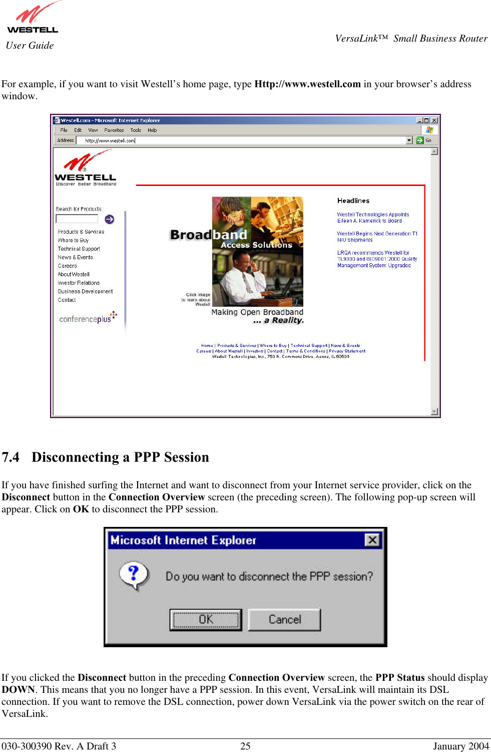
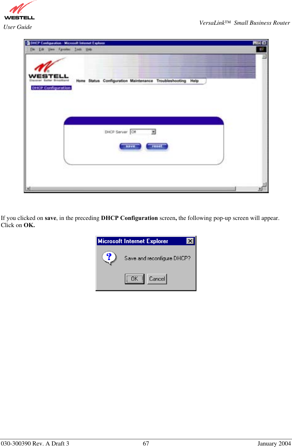
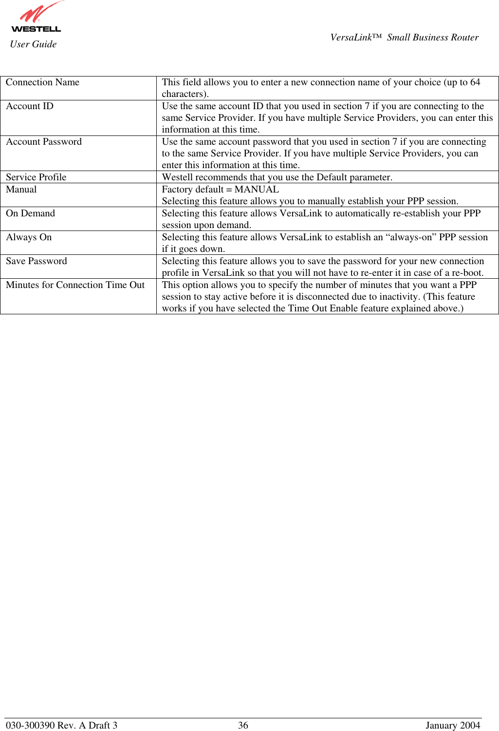
![030-300390 Rev. A Draft 3 31 January 2004 VersaLink™ Small Business Router User Guide The following sections explain the advanced features of VersaLink™. [This Page Left Blank Intentionally]](https://usermanual.wiki/Westell/327WXX-6.users-manual-page1-to-70/User-Guide-401961-Page-31.png)
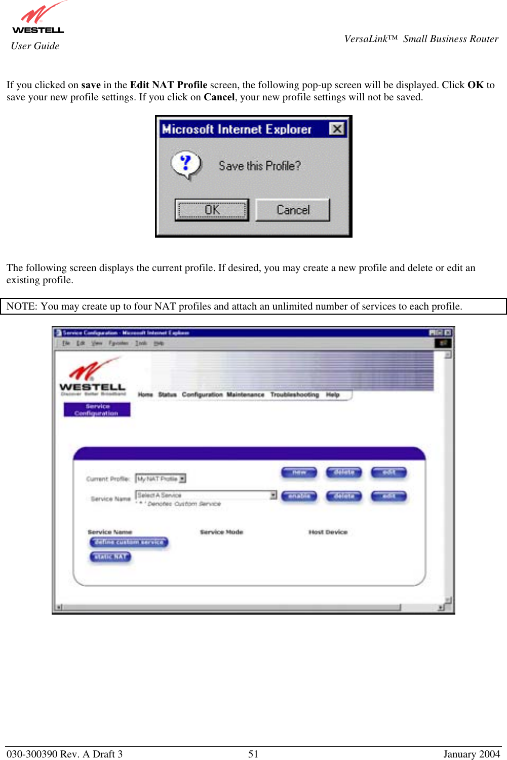
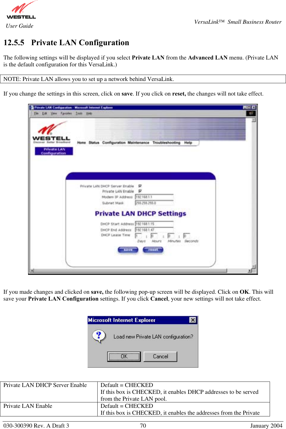
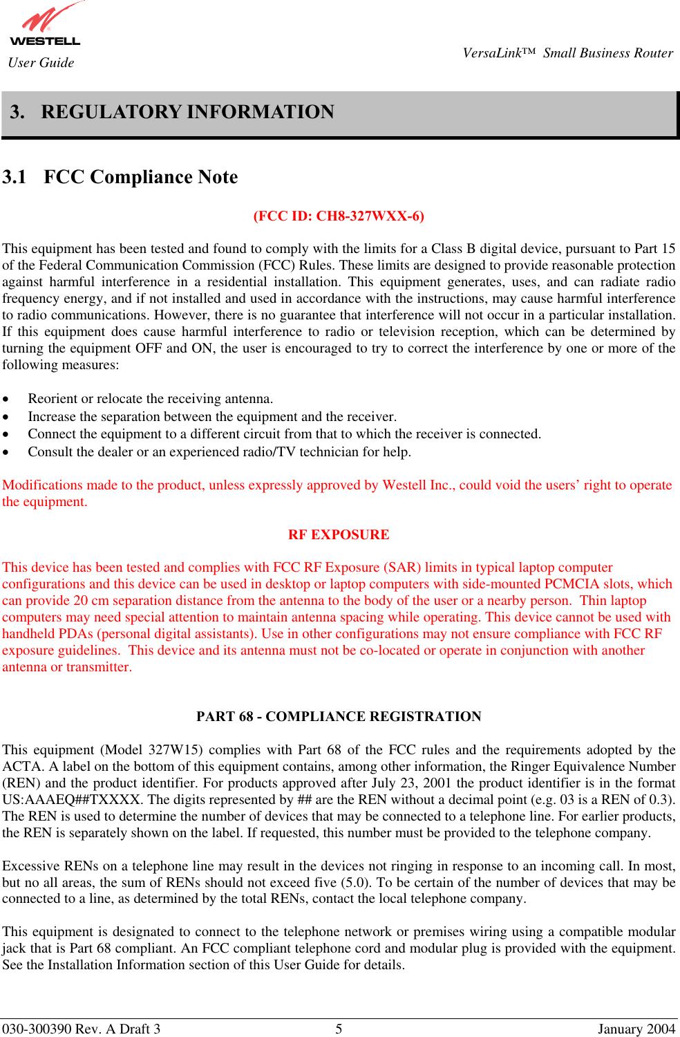
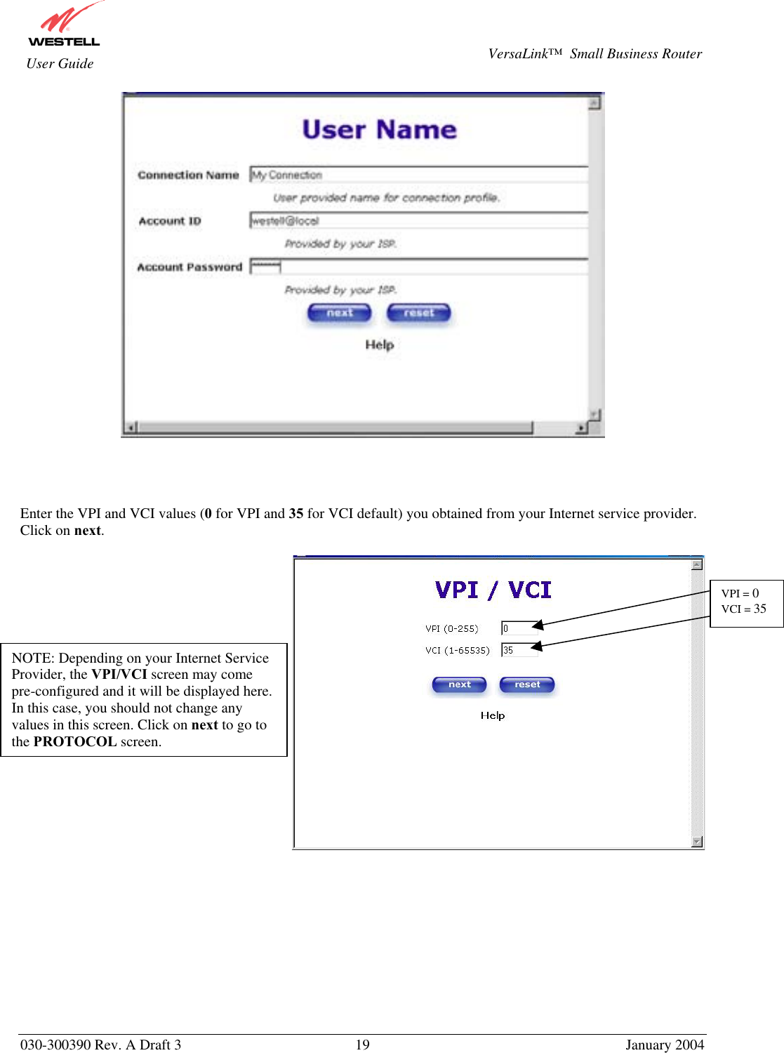
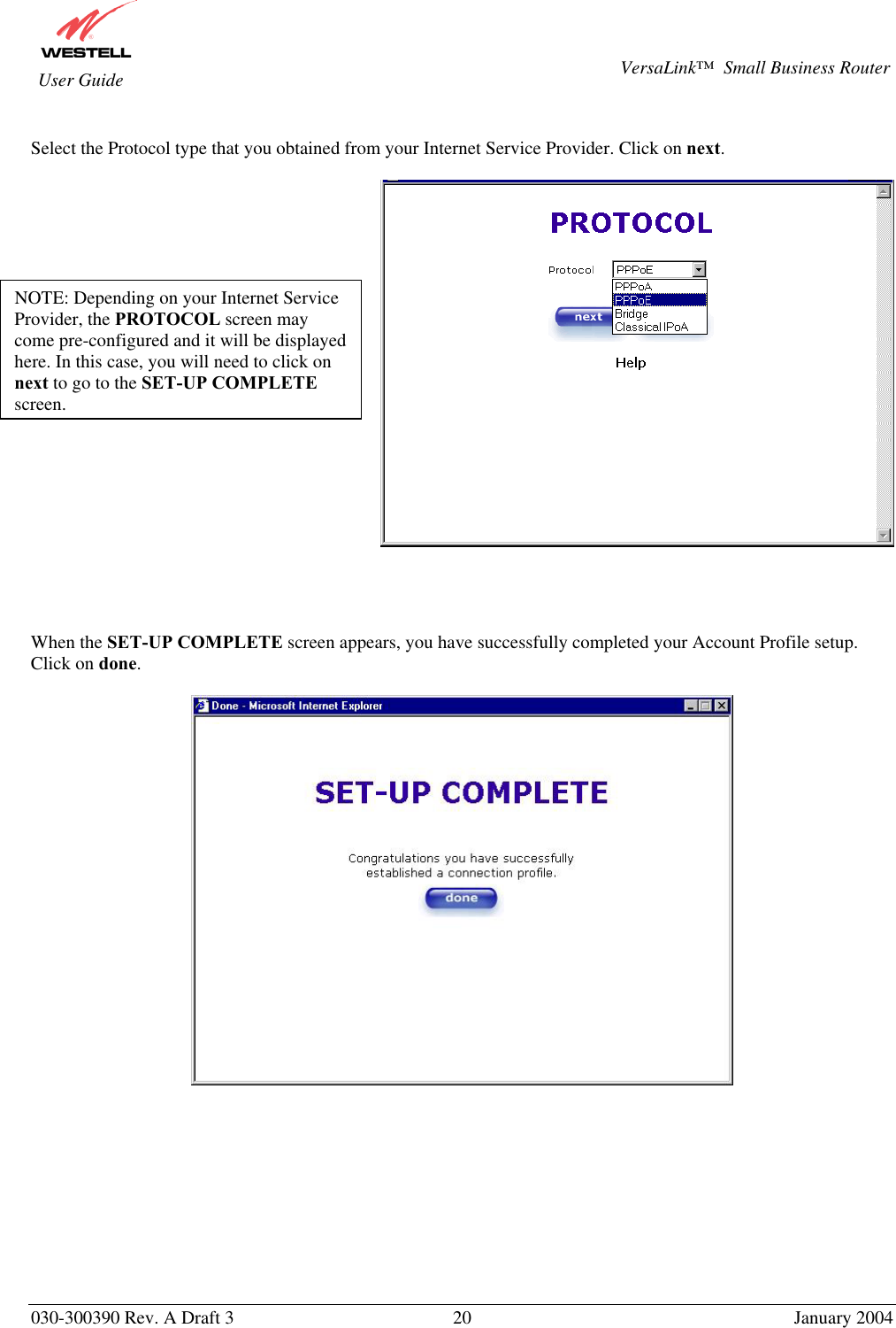
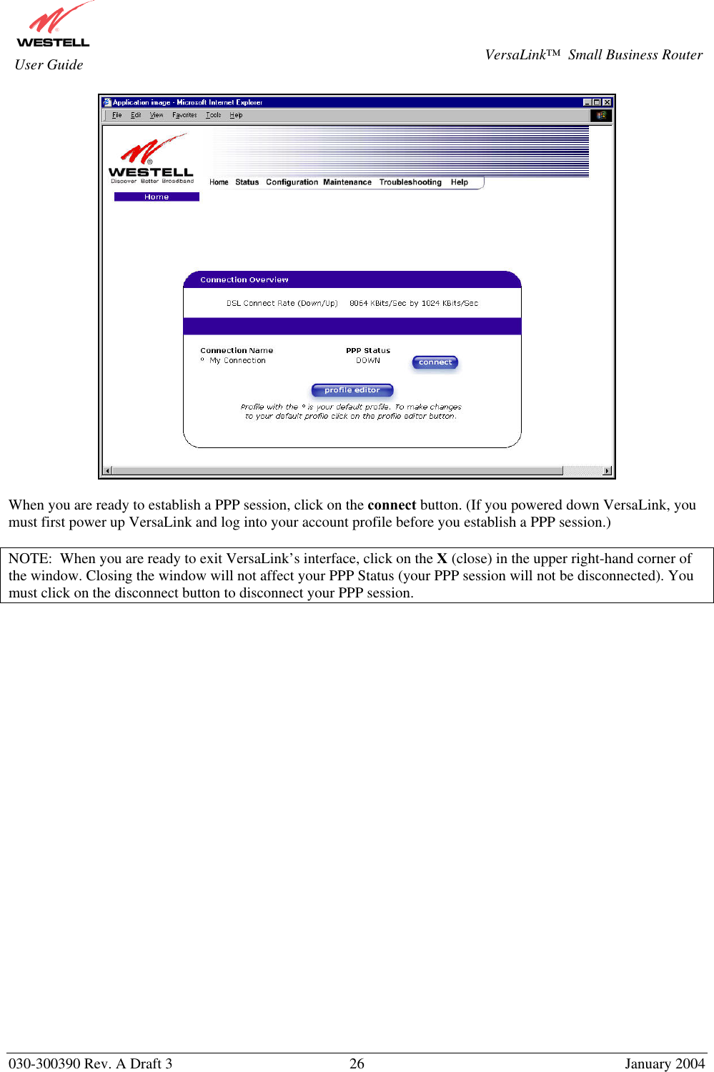
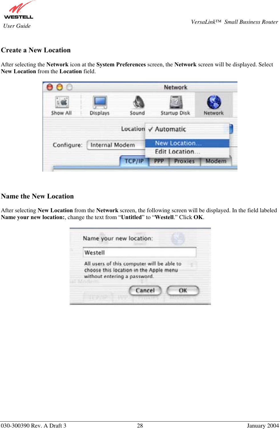
![030-300390 Rev. A Draft 3 44 January 2004 VersaLink™ Small Business Router User Guide STOP! After you disable Single Static IP, you must reboot your computer. 12.1.3 Configuring Static IP on Your PC If you have static IP service (your Internet Service Provider [ISP] supplies static IP addresses), you will need to perform the following steps to obtain Internet access: 1. Configure your PC settings to obtain an IP address automatically. (Refer to your Windows Help screen for instructions.) 2. Follow the instruct ions in section 7 (Configuring VersaLink™ for Internet Connection). 3. View the settings at the VPI/VCI screen (section 7). The values should read 0 (for VPI) and 35 (for VCI). If you type any other value in the fields and click on next, you will lose your DSL connection. The connection cannot be restored until the VPI/VCI is set to 0/35. 4. Select the Configuration menu, and then select Advanced WAN > VC. 5. Click on the edit button in the row that displays the VPI/VCI equal to 0/35. The VC 1 Configuration screen will be displayed. 6. Select Bridge from the list of Protocol options. Next, under the VC 1 Bridge Settings, select Routed Bridge as the Mode.](https://usermanual.wiki/Westell/327WXX-6.users-manual-page1-to-70/User-Guide-401961-Page-44.png)