Westell A9080YYXX-07 Spread Spectrum Transmitter User Manual 5662 Rev 1
Westell Inc Spread Spectrum Transmitter Users Manual 5662 Rev 1
UserManual.wiki
>
Westell
>
A9080YYXX 07 User Manual
Users Manual
Navigation menu
Upload a User Manual
Namespaces
Wiki Guide
HTML
PDF
Info
Views
User Manual
Discussion / Help
Navigation


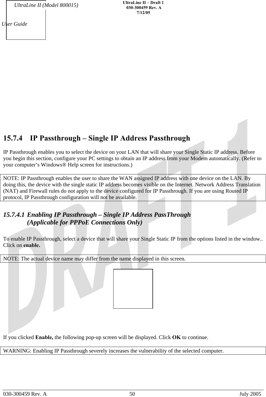
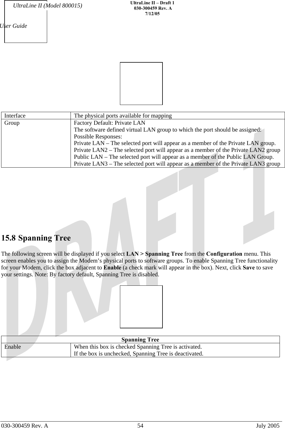
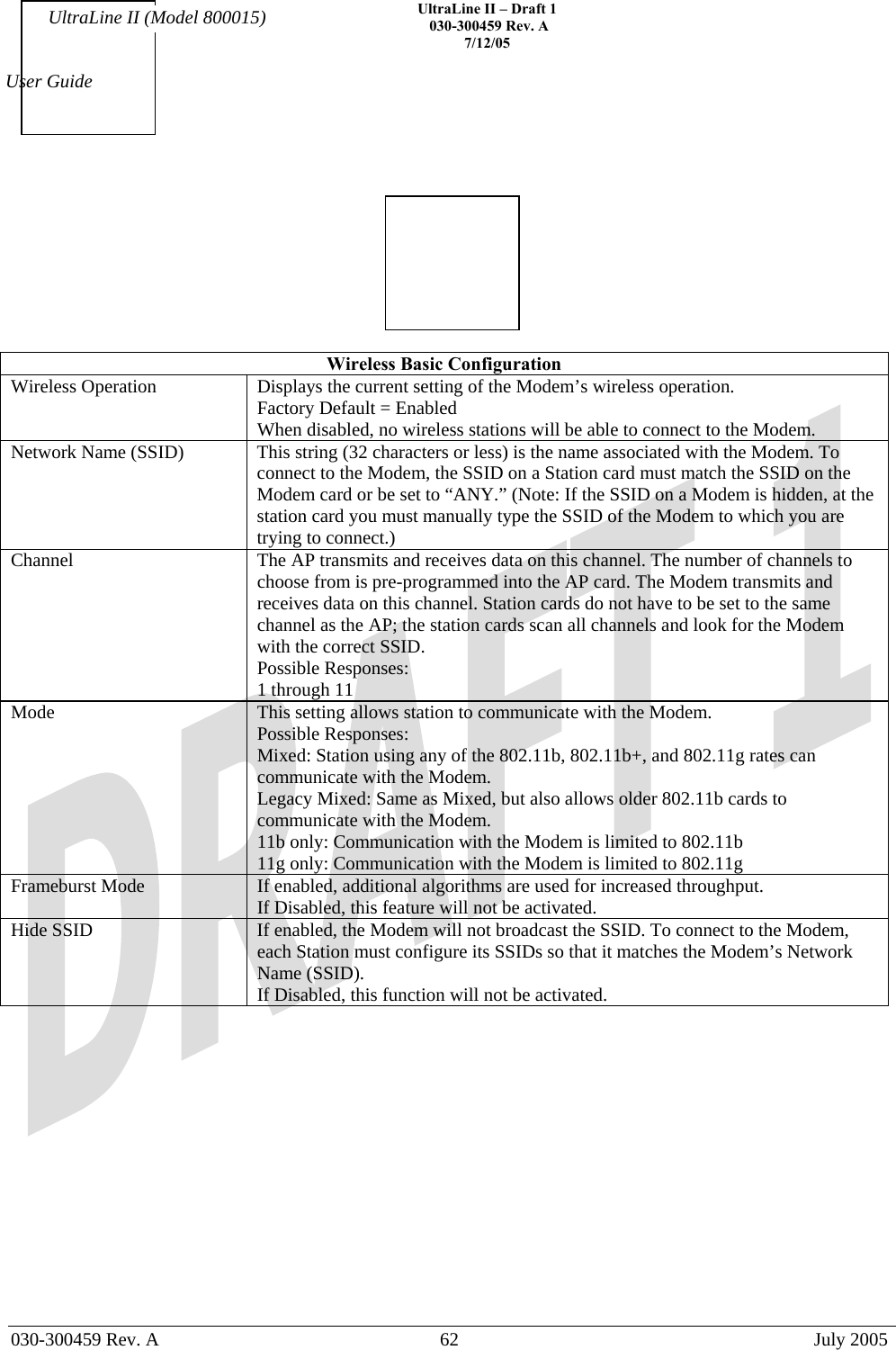
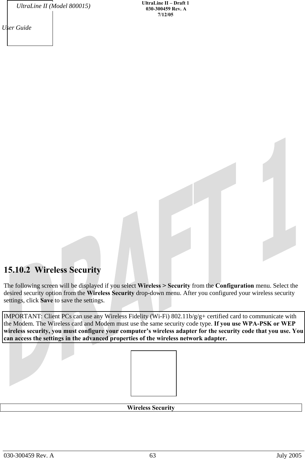
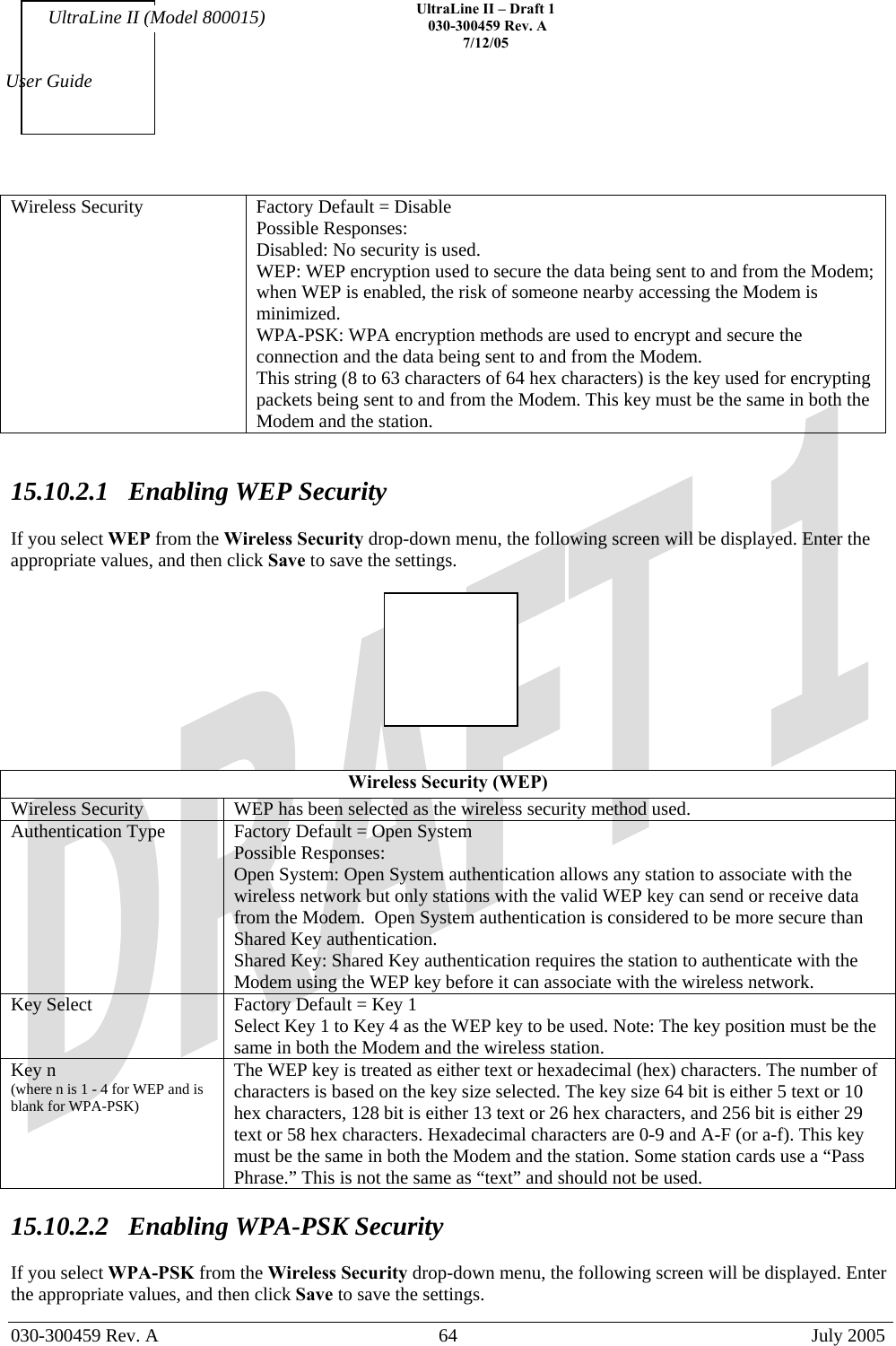
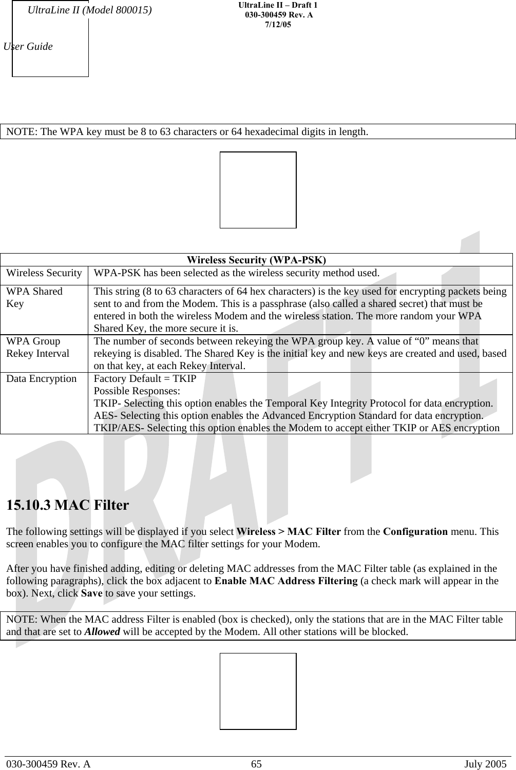
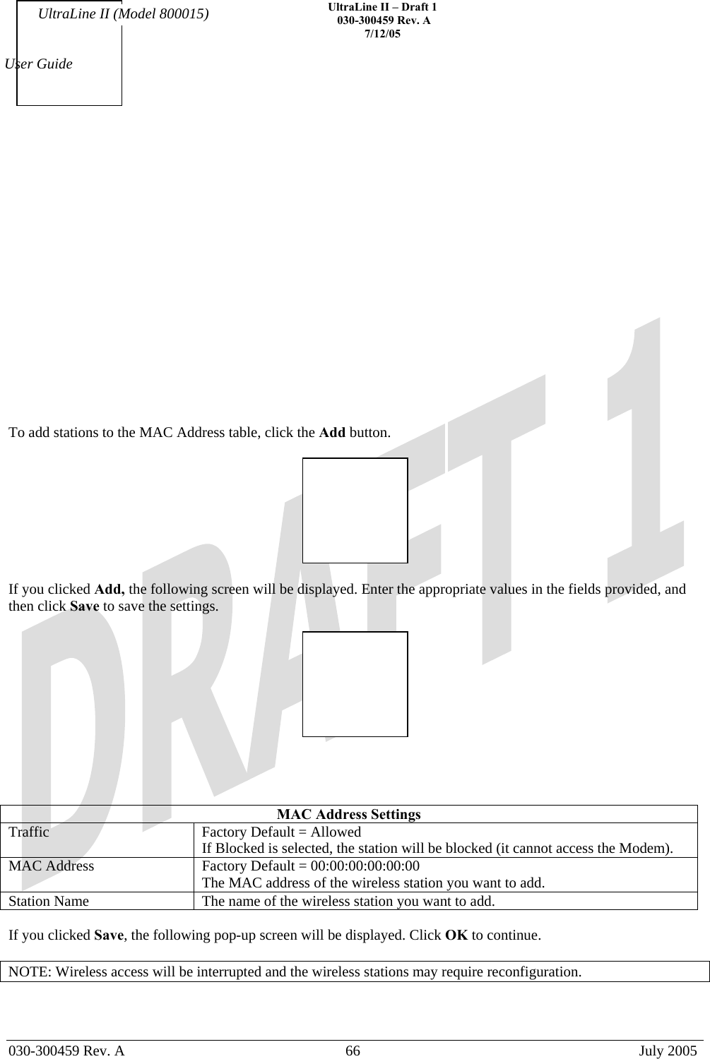
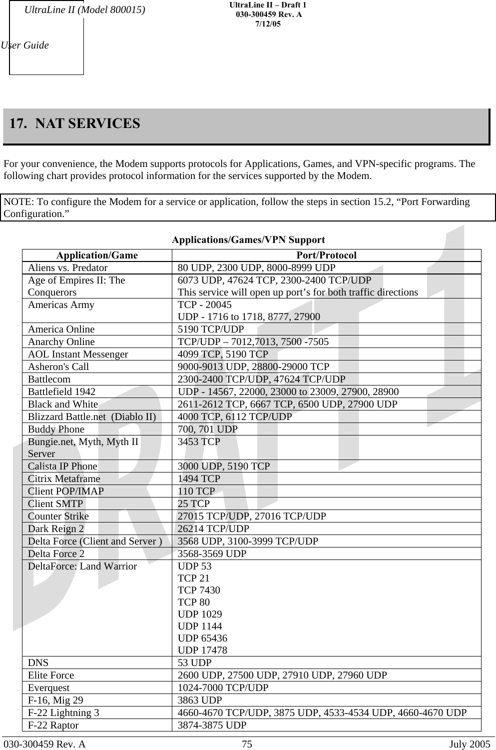
![UltraLine II – Draft 1 030-300459 Rev. A 7/12/05 030-300459 Rev. A 41 July 2005 User Guide UltraLine II (Model 800015) than the lowest port. RTP Timeout (in seconds) The number of seconds until a stream will time out. 15.5 IGMP Service The following screen will be displayed if you select IGMP from the Configuration menu. This screen enables you to configure the IGMP services for your Modem. Enter the appropriate settings and then click Save Settings to save the settings. To view the status of the settings, click Show Status. IGMP Internet Group Management Protocol (IGMP) enables you to configure IGMP services for your Modem. Enabled Factory Default = Enabled When this box is checked, IGMP service will be activated. To disable IGMP service, click to uncheck the box. MulticastFilter Factory Default = Disable When enabled (box is checked), MulticastFilter is activated. If disabled, MulticastFilter will be deactivated. Multicast Address Range 1 The first multicast address for IGMP. Multicast Address Mask Range 1 The network address mask for Multicast Address Range 1. Multicast Address Range 2 The second multicast address for IGMP. Multicast Address Mask Range 2 The network address mask for Multicast Address Range 2. General Query (seconds) The value in seconds (5 through 300) for doing queries. If you clicked Show Status in the preceding screen, the following screen will be displayed. [Need Screen w/ info.]](https://usermanual.wiki/Westell/A9080YYXX-07/User-Guide-590706-Page-41.png)

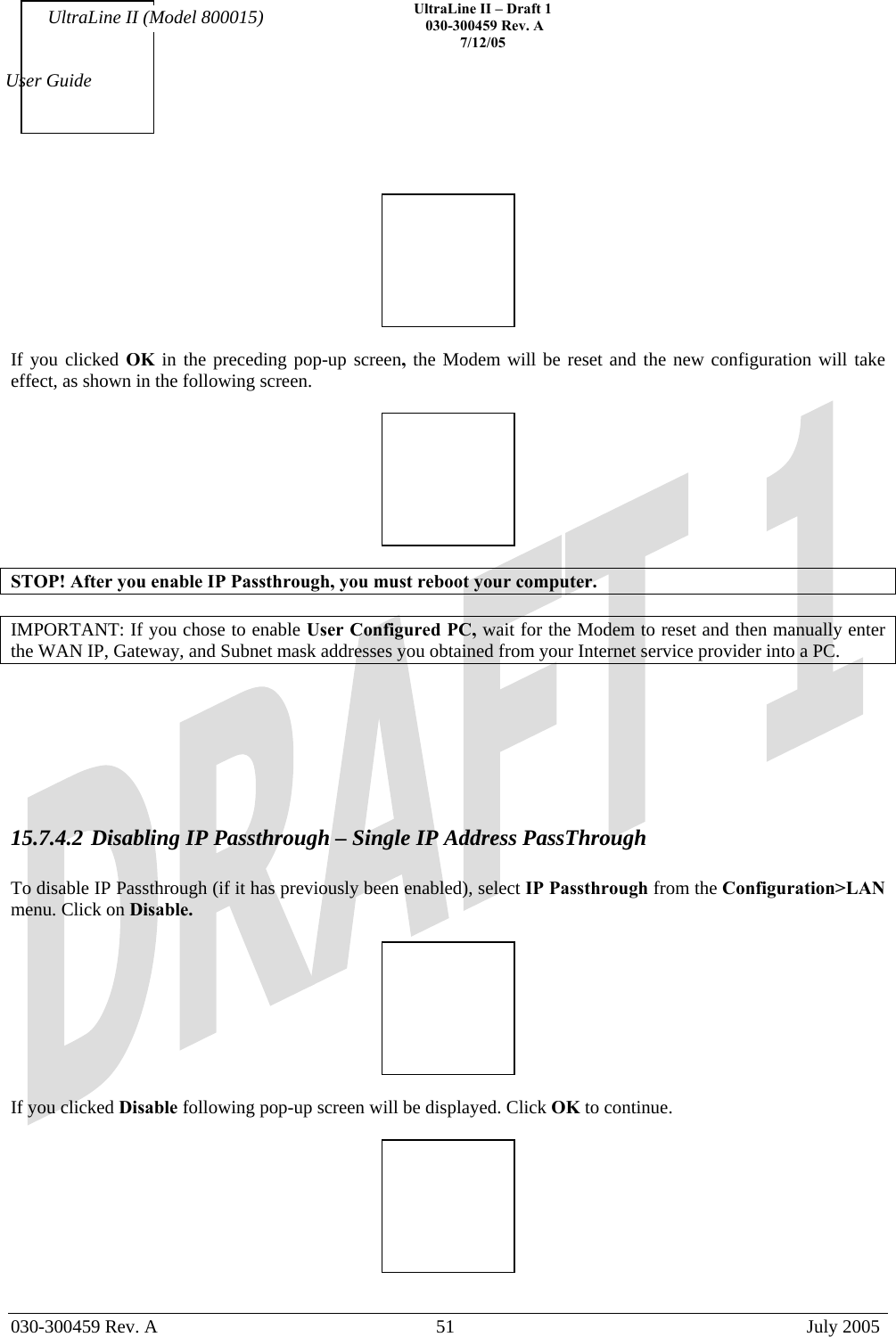

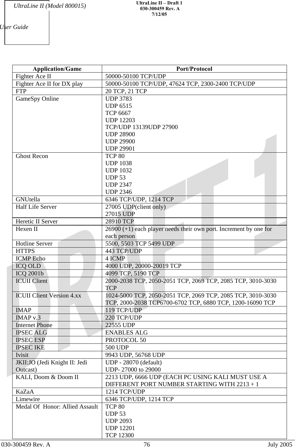
![UltraLine II – Draft 1 030-300459 Rev. A 7/12/05 030-300459 Rev. A 78 July 2005 User Guide UltraLine II (Model 800015) Application/Game Port/Protocol Starfleet Command 2300-2400 TCP/UDP, 47624 TCP/UDP SOF/SOFII (Soldier of Fortune / Soldier of Fortune II) UDP - 28910 to 28915 Telnet 23 TCP Tiberian Sun & Dune 2000 1140-1234, 4000 TCP/UDP Tribes2 TCP - 15104, 15204, 15206, 6660 to 6699 UDP - 27999 to 28002 Ultima Online 5001-5010 TCP, 7775-7777 TCP, 8800-8900 TCP, 9999 UDP, 7875 UDP Unreal Tournament server 7777 (default gameplay port) 7778 (server query port 7779,7779+ are allocated dynamically for each helper UdpLink objects, including UdpServerUplin objects. Try starting with 7779-7781 and add ports if needed 27900 server query, if master server uplink is enabled. Home master servers use other ports like 27500 Port 8080 is for UT Server Admin. In the [UWeb.WebServer] section of the server.ini file, set the ListenPort to 8080 and ServerName to the IP assigned to the Modem from your ISP. USENET News Service 143 TCP VNC, Virtual Network Computing 5500 TCP, 5800 TCP, 5900 TCP Westwood Online, C&C 4000 TCP/UDP, 1140-1234 TCP/UDP World Wide Web (HTTP) 80 TCP 443 TCP (SSL) 8008 OR 8080 TCP (PROXY) Yahoo Messenger Chat 5000-5001 TCP Yahoo Messenger Phone 5055 UDP IPSec Encryption IPSec using AH can not be supported through NAT. IPSec using ESP and L2TP can be supported via an ALG L2TP IPSec using ESP and L2TP can be supported via an ALG. PPTP Works through NAT.](https://usermanual.wiki/Westell/A9080YYXX-07/User-Guide-590706-Page-78.png)