Westell A90WMT-00 Media Terminal with Wireless LAN User Manual revised 5833 Draft1
Westell Inc Media Terminal with Wireless LAN revised 5833 Draft1
UserManual.wiki
>
Westell
>
A90WMT-00 User Manual
>
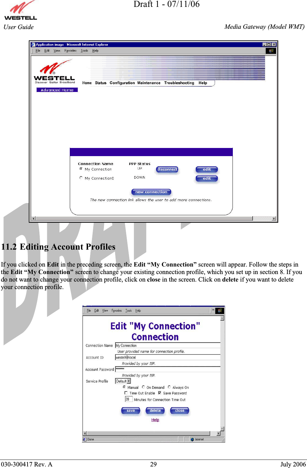
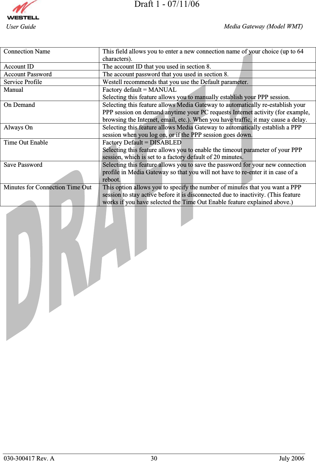
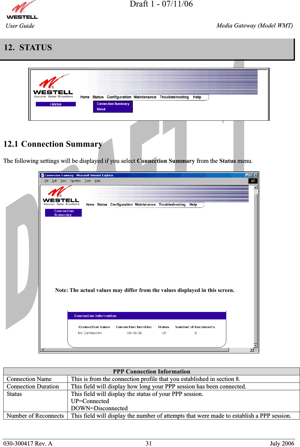
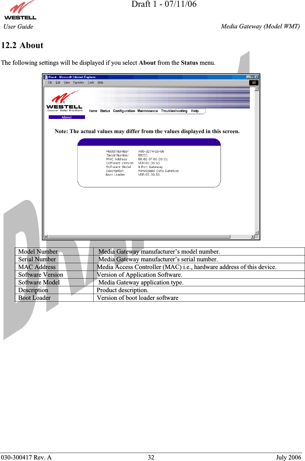
User Manual Part 1
Contents
1.
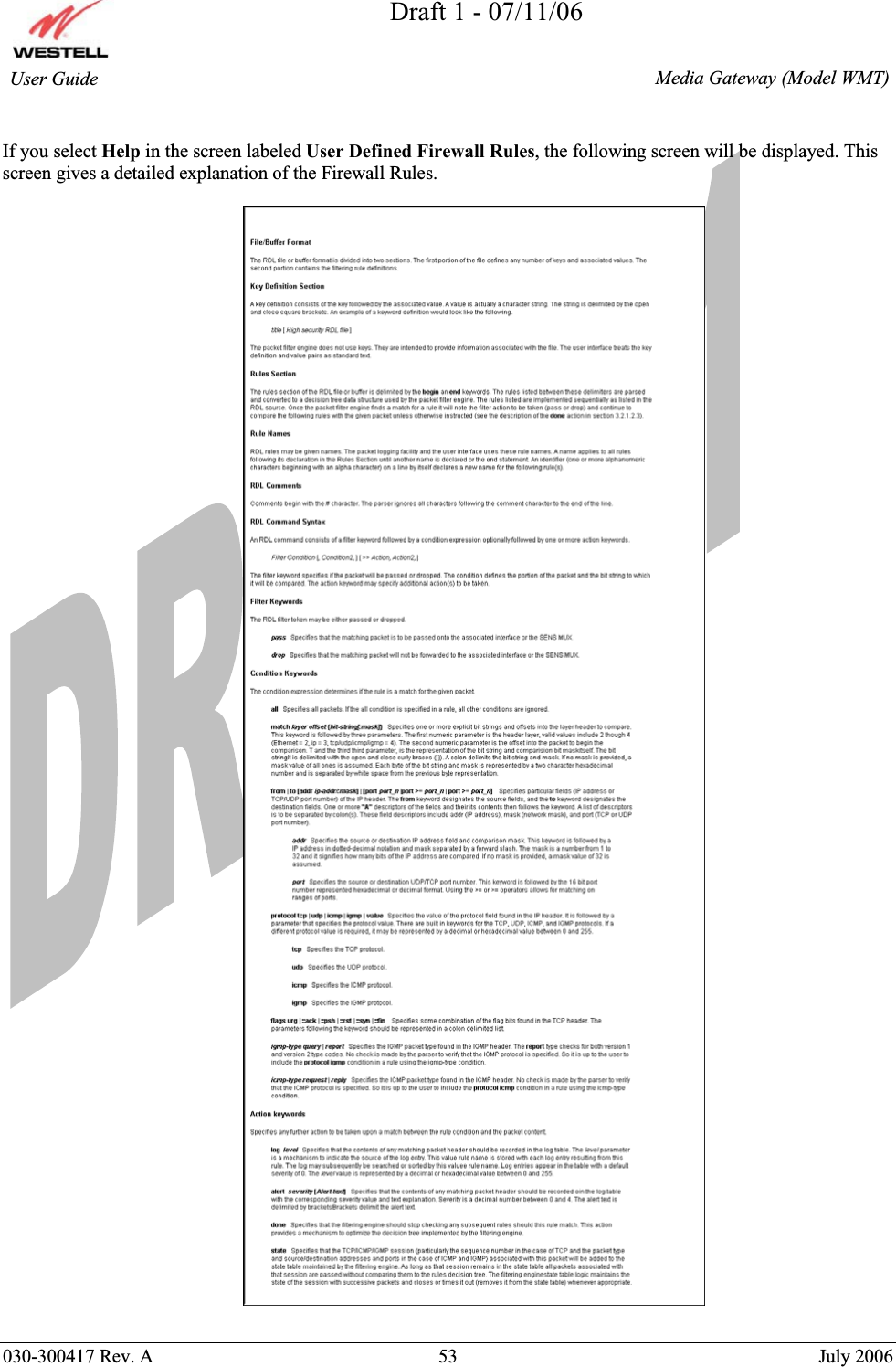
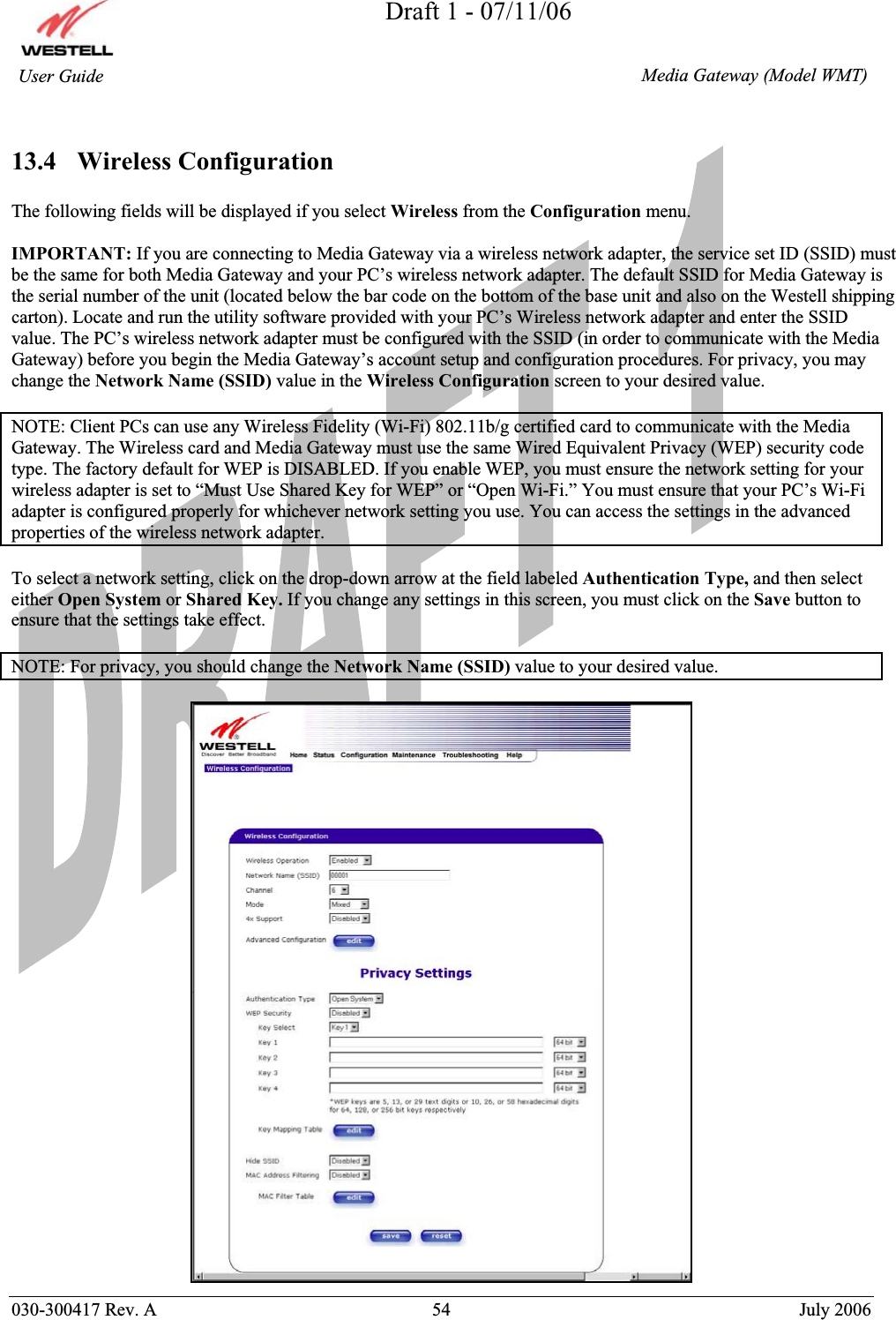
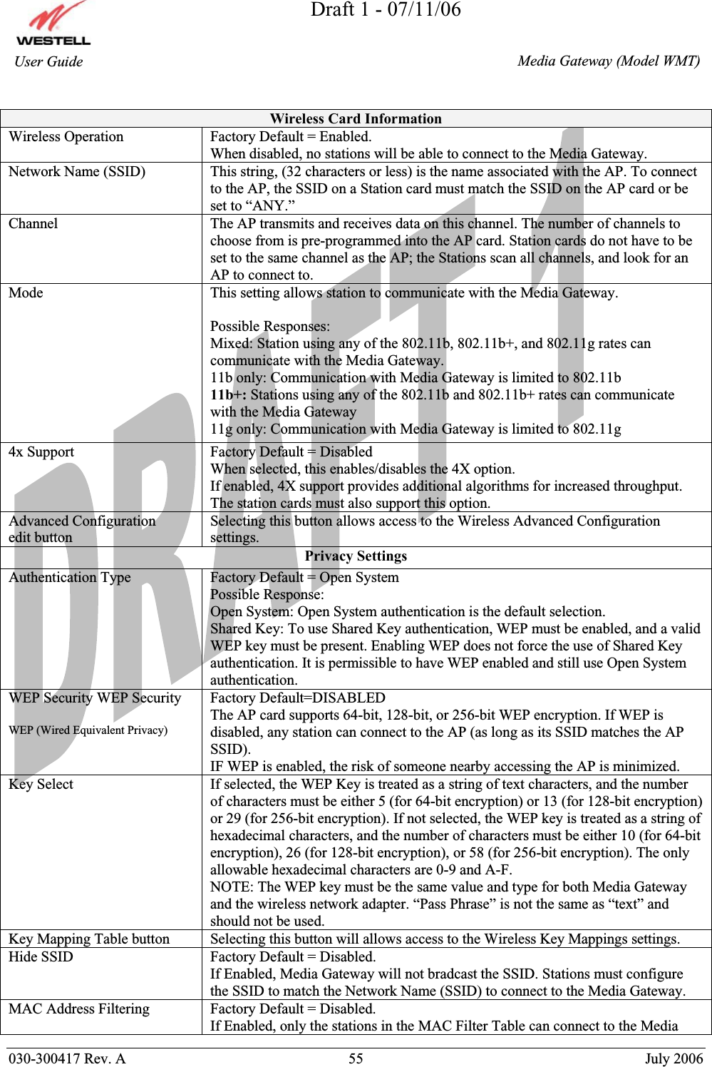
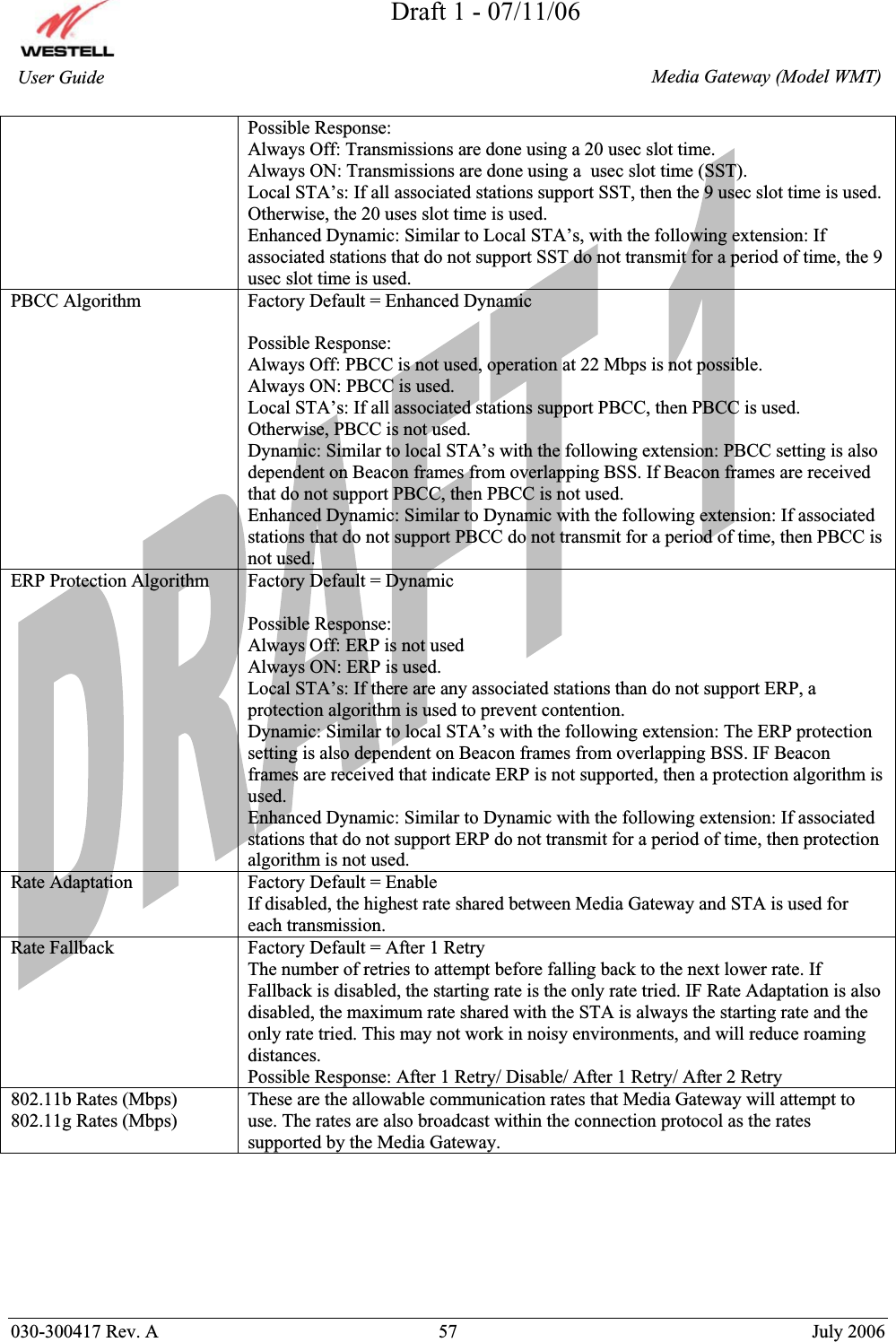
User Manual Part 1
2.
User Manual Part 2
User Manual Part 1
Navigation menu
Upload a User Manual
Namespaces
Wiki Guide
HTML
PDF
Info
Views
User Manual
Discussion / Help
Navigation