Westell AR210 User Manual operational manual
Westell Inc operational manual
UserManual.wiki
>
Westell
>
AR210 User Manual
operational manual
Navigation menu
Upload a User Manual
Namespaces
Wiki Guide
HTML
PDF
Info
Views
User Manual
Discussion / Help
Navigation


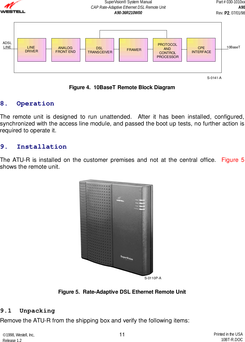
![SuperVision® System ManualCAP Rate-Adaptive Ethernet DSL Remote UnitA90-36R210W00Part # 030-1010xxA90Rev. P2, 07/01/981998, Westell, Inc.Release 1.2 Printed in the USA10BT-R.DOC139.3.1 Installation with an Internal POTS SplitterTIPRING3445DSL TIPDSL RINGPHONE (RJ11) LINERX+RX-TX+TX-10BaseTTO CPE]1236ATU-RS-0111-AFigure 6. Installation Diagram with an Internal POTS SplitterUse the following procedure: 1. Connect the power transformer to the back of the unit and then plug into the wallpower receptacle. 2. Connect either an 8-pin module cable or a standard 6-pin telephone cable from theLINE connector on back of the unit to the network jack. 3. Connect the proper Ethernet cable from the 10BaseT connector to the interface onthe CPE equipment (for example, the PC NIC card). 4. Connect the phone to connector phone connection on the back of the unit. 5. Power the unit ON. 6. By observing the READY LED, check the unit to ensure that the power self-test hassuccessfully completed, and that the unit is synchronized with the access linemodule. It may take from 50 to 70 seconds for the unit to achieve line synchronizationwith the central office ADSL unit. The READY LED illuminates to a steady green toshow that the unit is synchronized. 7. Verify the connection to the CPE by observing the LINK and ACTIVITY LEDs on thefront of the unit.](https://usermanual.wiki/Westell/AR210/User-Guide-4529-Page-17.png)
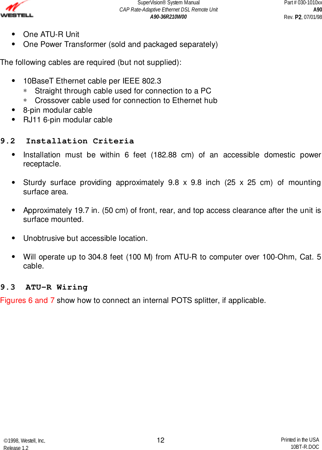
![SuperVision® System ManualCAP Rate-Adaptive Ethernet DSL Remote UnitA90-36R210W00Part # 030-1010xxA90Rev. P2, 07/01/981998, Westell, Inc.Release 1.2 Printed in the USA10BT-R.DOC149.3.2 Installation without an Internal POTS Splitter45DSL TIPDSL RINGLINERX+RX-TX+TX-10BaseTTO CPE]1236ATU-RS-0112-AFigure 7. Installation Diagram without a POTS SplitterUse the following procedure: 1. Connect the power transformer to the back of the unit and then plug into the wall powerreceptacle. 2. Connect the 8-pin module cable or a standard 6-pin telephone cable from the LINEconnector on back of the unit to a POTS splitter (refer to POTS splitter data sheet forinstructions) or to the network jack if POTS service is not provided. 3. Connect the proper Ethernet cable from the 10BaseT connector on the back of the unit tothe interface on the CPE equipment (for example, the PC NIC card). 4. Power the unit ON. 5. By observing the READY LED, check the unit to ensure that the power self-test hassuccessfully completed, and that the unit is synchronized with the access line module. Itmay take from 50 to 70 seconds for the unit to achieve line synchronization with thecentral office ADSL unit. The READY LED illuminates to a steady green to show that theunit is synchronized. 6. Verify the connection to the CPE by observing the LINK and ACTIVITY LEDs on the front ofthe unit.](https://usermanual.wiki/Westell/AR210/User-Guide-4529-Page-18.png)