Westell BA56X-01 BiDirectional Amplifier User Manual Report
Westell, Inc. BiDirectional Amplifier Report
Westell >
Exhibit D Users Manual per 2 1033 c3
Cellular Specialties, Inc.
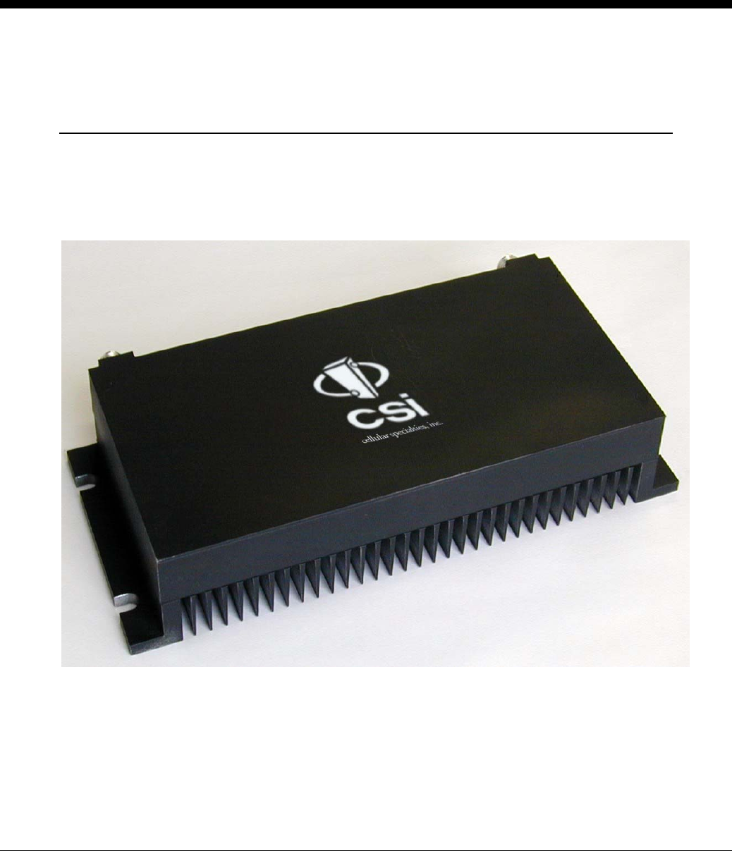
Model 565SMR In-Building Amplifier
Installation and Users Manual
The serial number may be found on the label on the rear panel of the unit. For your
convenience, note this number below, and retain this manual, along with proof of purchase , to
serve as a permanent record of your purchase in the event of a theft, or for future reference.
MODEL NUMBER
NAME OF COMPANY
DATE OF PURCHASE
565
SERIAL NUMBER
FCC ID: NVRBA56X-01
IC: 4307A-BA56X8
THIS DEVICE COMPLIES WITH PARTS 90 AND 2 OF THE FCC RULES, AND
WITH INDUSTRY CANADA SPECIFICATION RSS-131.
The term “IC” before the certification/registration number only signifies that the Industry Canada
specifications were met.
DISCLAIMER
All information and statements contained herein are accurate to the best of the knowledge of Cellular Specialties, but Cellular Specialties makes no warranty
with respect thereto, including without limitation any results which may be obtained from the products described herein or the infringement by such products of
any proprietary rights of any persons. Use or application of such information or statements is at the user's sole risk, without any liability on the part of Cellular
Specialties, Inc. Nothing herein shall be construed as license or of recommendation for use, which infringes upon any proprietary rights of any person.
Product material and specifications are subject to change without notice. All sales of the product or products described herein are subject to Cellular
Specialties' standard terms of sale and the specific terms of any particular sale.
TABLE OF CONTENTS
1.0 SAFETY GUIDELINES 3
2.0 PRODUCT DESCRIPTION 4
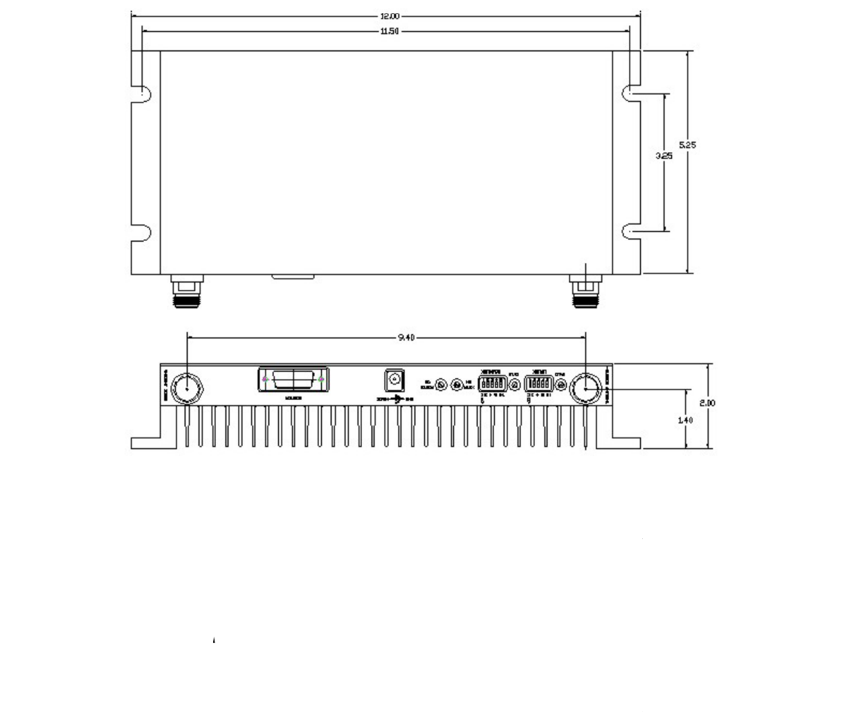
MECHANICAL OUTLINE DRAWING 5
3.0 GENERAL SPECIFICATIONS 6
4.0 INSTALLATION 7
5.0 AMPLIFIER ADJUSTMENT 9
6.0 TROUBLESHOOTING 10
MANUAL565 SMR REV A
960-1008-001
2

SAFETY GUIDELINES
1.0
The general safety information in this guideline applies to both operating
and service personnel. Specific warnings and cautions will be found in
other parts of this manual where they apply, but may not appear in this
summary. Failure to comply with these precautions or specific warnings
elsewhere in the manual violates safety standards of design,
manufacture, and intended use of equipment. Cellular Specialties, Inc.
assumes no liability for the customer's failure to comply with these
requirements.
!
GROUNDING
This amplifier system is designed to operate from single-phase 120VAC power and should
always be operated with both the neutral and ground wires properly connected. Do not
remove or otherwise alter the grounding lug on the power cord.
EXPLOSIVE ATMOSPHERES
To avoid explosion or fire, do not operate this product in the presence of flammable gases
or fumes.
LIGHTNING DANGER
Do not install or make adjustments to this unit during an electrical storm.
NO USER SERVICEABLE PARTS INSIDE
HAZARDOUS VOLTAGES ARE PRESENT WHEN THE COVER IS REMOVED.
Opening the chassis will void your warranty. If you suspect a malfunction with this product, call
your dealer or the Cellular Specialties Support Line at (603) 626-6677.
MANUAL565 SMR REV A
960-1008-001
3
PRODUCT DESCRIPTION
Cellular Specialties, Inc. developed the Model 565SMR Bi-Directional Amplifier (BDA) for use in
enclosed structures where sufficient signal from local cell sites to operate cell phones was unavailable
within the building. It is necessary that sufficient signal be available on the roof of the structure. The
BDA is connected to an external antenna, usually on the roof, and to one or more internal antennas
placed strategically throughout the area where phone service is desired.
The external antenna is an omni-directional antenna. Internal antennas are usually omni-directional
although various other types may be used for certain installations. The BDA amplifies both the "uplink"
(phone to tower) and "downlink" (tower to phone) signals thus facilitating communications to and from
the local cell site.
There are four amplification stages on the downlink and four on the uplink for a total of +65dB nominal
gain for each link. Both links have manual gain control settings accessed through DIP switches on the
rear of the unit plus an AGC control for both the uplink and downlink. There are LED indicators for
power on, transmitter on, uplink overload and downlink overload.
An automatic amplifier safety shutdown circuit is also provided, which will disable the transmitters for
ten seconds should the uplink or downlink overloads be reached to prevent excessive intermodulation
and oscillation.
The BDA is equipped with an interface connector designed for use with the optional CSI-MHH External
Monitor. The pin-out of the MONITOR connector is shown below.
Pin Description
1 Alarm Relay - Common
2 N/C
3 Shutdown (Input TTL)
4 Uplink Power
5 Alarm Relay – Active Open
6 N/C
7 Uplink AGC Level
8 Ground
9 Alarm Relay – Active Closed
10 N/C
11 Downlink AGC Level
12 +5 VDC
13 Uplink Overload
14 Downlink Overload
15 Downlink Power
2.0
MANUAL565 SMR REV A
960-1008-001
4
MANUAL565 SMR REV A
960-1008-001
5
OUTLINE DRAWING
3.0 GENERAL SPECIFICATIONS
All specifications stated as typical unless otherwise noted.
Uplink (Phone to Tower) Downlink (Tower to Phone)
Frequency (SMR) 806-821 MHz 851-866 MHz
Pass Band Ripple ±2.5 dB ±2.5 dB
Gain @ Zero Attenuation +65dB +65dB
Gain Adjustment Range -30dB -30dB
Linear Output Power * ** +27dBm +27dBm
Noise Figure 4.5dB 4.5dB
Maximum Input Power*** +15dBm +15dBm
VSWR 1.7:1 Max
Propagation Delay <200 nsec.
Impedance 50 Ohms
Connectors ‘N’ Female
Power Requirements +5 VDC @ 4000mA
Size 5.3” x 12.4” x 1.9”
Weight 8.8 Lbs., 4 kg
Operating Temperature 0 to +45° C
Indicator LEDs Power, Transmitter On, Uplink Overload, Downlink Overload
Controls AGC switch, Uplink and Downlink attenuation switches
0-30dB in 2dB steps.
NOTES
* The manufacturer’s rated output power of this equipment is for single carrier operation. For situations
when multiple carrier signals are present, the rating must be reduced by 3.5 dB, especially where the output
signal is re-radiated and can cause interference to adjacent band users. This power reduction is to be by means
of input power or gain reduction and not by an attenuator at the output of the device.
** Maximum total output power without exceeding the FCC allowable emissions of –13 dBm.
*** Maximum safe input power at maximum gain with no damage.
Cellular Specialties, Inc. reserves the right to change these specifications at any time without notice.
MANUAL565 SMR REV A
960-1008-001
6
4.0 INSTALLATION
CSI recommends that all BDA installations be coordinated through
the local wireless provider.
Note:
The Installer should refer to the Safety Precautions, in the
following section, for proper antenna selection and installation
!
WARNING!
AMPLIFIER DAMAGE WILL OCCUR IF A HANDSET IS
CONNECTED DIRECTLY TO THE BDA OR THE COAX THAT
LEADS TO THE BDA.
Important note: A high degree of isolation must be afforded to prevent any re-
generative feedback in the system. Feedback of this nature causes the
amplifier to emit a continuous signal of maximum amplitude and could, in
some cases, interfere with normal operation of the cell site. The minimum
required isolation of 80 dB can usually be obtained by mounting the outside
antenna away from the edges of the roof. The use of window mounts or other
non-rooftop mountings should be avoided.
MANUAL565 SMR REV A
960-1008-001
7
SAFETY PRECAUTIONS
!
For INDOOR use, an Omni-Directional Antenna with a maximum gain of 3 dBi
is authorized for use with this unit.
Inside antennas must be positioned to observe minimum separation of 20 cm.
(~ 8 in.) from all users and bystanders. For the protection of personnel working
in the vicinity of inside (downlink) antennas, the following guidelines for
minimum distances between the human body and the antenna must be
observed.
The installation of an INDOOR antenna must be such that, under normal
conditions, all personnel cannot come within 20 cm. (~ 8.0 in.) from any
inside antenna. Exceeding this minimum separation will ensure that the
employee or bystander does not receive RF-exposure beyond the
Maximum Permissible Exposure according to section 1.1310 Limits for
General Population/Uncontrolled Exposure.
!
For OUTDOOR use, an Omni-Directional Antenna with a maximum gain of
3dBi is authorized for use with this unit.
Outside antennas must be positioned to observe minimum separation of 20
cm. (~ 8 in.) from all users and bystanders. For the protection of personnel
working in the vicinity of inside (downlink) antennas, the following guidelines
for minimum distances between the human body and the antenna must be
observed.
The installation of an OUTDOOR antenna must be such that, under normal
conditions, all personnel cannot come within 20 cm. (~ 8.0 in.) from any
inside antenna. Exceeding this minimum separation will ensure that the
employee or bystander does not receive RF-exposure beyond the
Maximum Permissible Exposure according to section 1.1310 Limits for
General Population/Uncontrolled Exposure.
MANUAL565 SMR REV A
960-1008-001
8
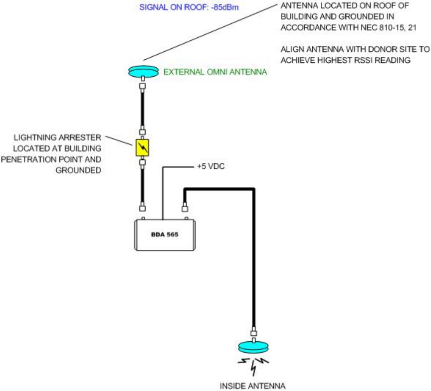
Example: Standard Single Internal Antenna System Design
MANUAL565 SMR REV A
960-1008-001
9

AMPLIFER ADJUSTMENT
5.0
In most cases the BDA will need very little adjustment. After connecting the coax and
powering up the BDA, the signal levels within the previously surveyed areas should
be checked for adequate RSSI levels. Measurements should be made at the
perimeter of the building both inside and outside. It is important that the RSSI levels
measured outside the building remain close to those measured prior to installation of
the BDA.
Both the uplink and downlink overload indicators should remain off. If either indicator
is illuminated, the gain of the appropriate link should be reduced.
If the gain of the amplifier needs adjustment the uplink and the downlink may be
adjusted by means of the step attenuators on the rear of the unit. Attenuation from 0
dB to 30 dB in steps of 2 dB may be inserted by proper selection of the 2, 4, 8 and 16
dB attenuators. If satisfactory cell (or two-way) phone performance is not obtained
when the phone is in close proximity to the interior antenna it may be necessary to
decrease the gain of one or both of the links.
MANUAL565 SMR REV A
960-1008-001
1
0

MANUAL565 SMR REV A
960-1008-001
11
6.0 TROUBLESHOOTING
All cables should be carefully checked for “shorts” and “opens”.
If cables are O.K. it may be necessary to use a spectrum analyzer to examine the
signal environment in which the BDA is operating. The existence of strong analog
signals within the frequency bands can cause problems particularly on the downlink.
There may be some cases where the interference from outside signals is so great
that they can not be filtered or otherwise reduced or eliminated without expensive
and possibly prohibitive measures. In these cases it may not be practical to use the
BDA for providing coverage at these sites.